EP4428312A1 - Retractable hose management system - Google Patents
Retractable hose management system Download PDFInfo
- Publication number
- EP4428312A1 EP4428312A1 EP24162042.6A EP24162042A EP4428312A1 EP 4428312 A1 EP4428312 A1 EP 4428312A1 EP 24162042 A EP24162042 A EP 24162042A EP 4428312 A1 EP4428312 A1 EP 4428312A1
- Authority
- EP
- European Patent Office
- Prior art keywords
- hose
- sprayhead
- pully
- faucet
- examples
- Prior art date
- Legal status (The legal status is an assumption and is not a legal conclusion. Google has not performed a legal analysis and makes no representation as to the accuracy of the status listed.)
- Pending
Links
- 230000002441 reversible effect Effects 0.000 claims description 37
- 230000007704 transition Effects 0.000 claims description 18
- 239000012530 fluid Substances 0.000 claims description 10
- 230000000712 assembly Effects 0.000 abstract description 4
- 238000000429 assembly Methods 0.000 abstract description 4
- XLYOFNOQVPJJNP-UHFFFAOYSA-N water Substances O XLYOFNOQVPJJNP-UHFFFAOYSA-N 0.000 description 13
- 238000010168 coupling process Methods 0.000 description 7
- 238000005859 coupling reaction Methods 0.000 description 7
- 239000007921 spray Substances 0.000 description 6
- 230000008878 coupling Effects 0.000 description 4
- 230000001419 dependent effect Effects 0.000 description 4
- 238000000034 method Methods 0.000 description 4
- 238000010348 incorporation Methods 0.000 description 3
- 230000001105 regulatory effect Effects 0.000 description 3
- 238000009434 installation Methods 0.000 description 2
- 238000012986 modification Methods 0.000 description 2
- 230000004048 modification Effects 0.000 description 2
- 229910000831 Steel Inorganic materials 0.000 description 1
- 230000003213 activating effect Effects 0.000 description 1
- 239000000853 adhesive Substances 0.000 description 1
- 230000001070 adhesive effect Effects 0.000 description 1
- 230000008901 benefit Effects 0.000 description 1
- 230000005484 gravity Effects 0.000 description 1
- 238000004519 manufacturing process Methods 0.000 description 1
- 239000000463 material Substances 0.000 description 1
- 238000003032 molecular docking Methods 0.000 description 1
- 230000004044 response Effects 0.000 description 1
- 230000000284 resting effect Effects 0.000 description 1
- 238000005507 spraying Methods 0.000 description 1
- 239000010959 steel Substances 0.000 description 1
Images




Classifications
-
- E—FIXED CONSTRUCTIONS
- E03—WATER SUPPLY; SEWERAGE
- E03C—DOMESTIC PLUMBING INSTALLATIONS FOR FRESH WATER OR WASTE WATER; SINKS
- E03C1/00—Domestic plumbing installations for fresh water or waste water; Sinks
- E03C1/02—Plumbing installations for fresh water
- E03C1/04—Water-basin installations specially adapted to wash-basins or baths
-
- E—FIXED CONSTRUCTIONS
- E03—WATER SUPPLY; SEWERAGE
- E03C—DOMESTIC PLUMBING INSTALLATIONS FOR FRESH WATER OR WASTE WATER; SINKS
- E03C1/00—Domestic plumbing installations for fresh water or waste water; Sinks
- E03C1/02—Plumbing installations for fresh water
- E03C1/04—Water-basin installations specially adapted to wash-basins or baths
- E03C1/0404—Constructional or functional features of the spout
-
- E—FIXED CONSTRUCTIONS
- E03—WATER SUPPLY; SEWERAGE
- E03C—DOMESTIC PLUMBING INSTALLATIONS FOR FRESH WATER OR WASTE WATER; SINKS
- E03C1/00—Domestic plumbing installations for fresh water or waste water; Sinks
- E03C1/02—Plumbing installations for fresh water
- E03C1/04—Water-basin installations specially adapted to wash-basins or baths
- E03C2001/0415—Water-basin installations specially adapted to wash-basins or baths having an extendable water outlet
Definitions
- the present disclosure relates generally to the field of kitchen fixtures.
- the present disclosure relates to hose management assemblies for extending and retracting a sprayhead from a spout for docking.
- Conventional faucets have a faucet body, one or more flow control/mixing valves, one or more control handles, and a spout.
- the spout acts as a conduit for expelling water that has passed through the valve(s), in which case the outflow is either fixed to begin at a single point, or in the case of a pivotal spout, is limited to begin over a range of a prescribed horizontal arc.
- Faucets have conventionally been provided with separate stand-alone hand-held sprayers to provide the user with more flexibility with regard to the direction and point that outflow begins, particularly to facilitate spraying down dishware.
- These sprayers have a flexible hose attached to a sprayhead allowing the sprayhead to be pulled from a mount and moved about as needed.
- these faucets require extra room on the countertop for the sprayer mounting, as well as a separate hole through the countertop itself.
- faucets with pull-out sprayheads projecting from the main faucet body have been developed. Assembly of such pull-out faucets can be more complicated than conventional faucets due to the added spray hose and its coupling to the water supply lines.
- the spray hose must run through the body of the faucet near the valve assembly, which itself typically includes a large number of components. Also, separate fasteners are ordinarily needed to install the valve assembly in the faucet body. This can significantly increase the cost of production of the faucet, and in some cases the shipping weight of the product.
- the types of assemblies can be complex and take up a large amount of storage capacity below or near the sink.
- the hose and other movable parts may disturb, tangle up with or otherwise interfere with other hoses, waterlines, or other items stored beneath the sink or with the environment itself.
- Non-limiting examples of the present disclosure provide a retractable sprayhead hose management system including a pully assembly including a plurality of first pullies, and a second pully operably coupled to the first pullies and a hose assembly body, wherein the first pullies are coupled to the body such that the first pullies remain secured to the body during operation, while maintaining rotational capability.
- the second pully may be securely housed within one or more openings of the body, such that the second pully is enabled to move vertically or axially along the body.
- the first pullies and second pully each having defined grooves configured to receive a hose, at least in part, wherein a first end of the hose is connected to a sprayhead of a faucet and the second end of the hose is connected to a mixing valve positioned within the faucet.
- the hose wraps around the second pully such that extension of the sprayhead from the faucet tightens the hose around the first pullies and second pully and lifts the second pully as the sprayhead is further extended away from the faucet.
- the weight of the second pully provides a force onto the hose such that the second pully retracts the sprayhead back into the faucet.
- a sprayhead hose retraction system including a first pully and a second pully operably coupled within a housing of a sink and faucet assembly.
- the pullies may include a guide pully and an adjacent tension pully operably and rotatably coupled within the housing, wherein the pullies are defined with grooves configured to receive a hose, at least in part.
- the hose configured to be wrapped, at least partially, around the pullies such that, when a sprayhead transitions between a retracted and an extended position, the hose is pulled through the spout and about/around the pullies and, in turn, pulls together the tension pully closer to the guide pully.
- a sprayhead hose retraction assembly for use with faucet assemblies having a retractable spray head or hand spray is shown according to various examples.
- the faucet assembly generally includes a body, a spout, and a retractable sprayhead releasably coupled (e.g., removably coupled, selectively coupled, etc.) to the spout via a retractable hose.
- One or more hoses carry fluid through the spout from a mixing valve coupled to hot and cold waterlines to the sprayhead, where the fluid is dispensed (e.g., released, sprayed, output) to the environment, for example, into a basin, sink, tub, shower stall, etc.
- a sprayhead hose retraction system 100 for use with a faucet assembly 101 is shown, according to examples.
- the faucet assembly 101 and hose retraction system 100 is shown in a retracted (e.g., first, docked, retracted. etc.) position.
- the faucet assembly 101 is shown to include a base 102, a spout 104, and a sprayhead 106 removably coupled to (e.g., received in, engaging, etc.) the spout 104 via a hose 110 that extends within the faucet assembly 101.
- a first end 110A of the hose is coupled to a mixing valve (not shown) positioned within the faucet, which is in turn coupled to a hot water inlet hose or flow line (not shown) and a cold water inlet hose or flow line (not shown), each of which are coupled to a source of hot water H inlet and a source of cold water C, respectively.
- the sprayhead 106 may be coupled to and received in the spout 104.
- a sprayhead retraction system is configured to retract the sprayhead 106 from an extended position to the retracted position.
- the faucet assembly 101 is shown to include an arm 108 configured to house and support a manual or digital mixing valve (not shown).
- the valve may be configured to control the volume, temperature, or some combination thereof, of the fluid flow through the faucet assembly 101 via hose 110.
- a handle 120 is coupled to the valve to control the operation thereof.
- the faucet assembly 101 may not include an arm 108, and the valve and handle 120 may be located remotely from the faucet 101.
- the faucet assembly may not include an arm 108 and handle 120 and may activate fluid flow through the faucet assembly 101 by activating one or more touch sensors positioned at one or more locations on the base 102, spout 104, sprayhead 106, etc.
- the faucet 101 may include an electronically controlled valve (e.g., solenoid valve) in addition to or instead of the manual valve.
- the faucet assembly 101 is operable with the sprayhead hose retraction system 100 to transition the sprayhead 106 between a retracted position and an extended position.
- the faucet assembly 101 may include a fully extended position (e.g., a position in which the hose 110 may no longer be extended) and a plurality of partially extended positions (e.g., a position between the fully extended position and the retracted position).
- the sprayhead hose retraction system 100 applies a force (e.g., constant force, variable force) to the hose 110 and the sprayhead 106 in the direction of the retracted position.
- the transition of the sprayhead 106 between the retracted position and the extended position may be accomplished through the use of a pully/hose assembly 130 of the sprayhead hose retraction system 100.
- the pully/hose assembly 130 may include a plurality of pullies 134A-134B and a weighted pully 136 operably and rotatably coupled to a pully/hose assembly body ("body") 132.
- pullies 134A-134B may be coupled to the body 132 via attachable members 135 such that the pullies 134A-134B may remain secured to the body 132 during operation, while maintaining rotational capability.
- the body 132 may be generally hollow in nature, while being structurally sound, and have a plurality of openings, for example openings 150A-150B between uprights.
- the weighted pully 136 may be securely housed within the openings 150A-150B of the body 132.
- the weighted pully 136 may be configured to remain within the pully opening 150A, wherein member openings 150B are configured to receive slidable members 137 integrated with the weighted pully 136 such that weighted pully 136 is axially slidable along opening 150A.
- the plurality of pullies 134A-134B and weighted pully 136 with defined grooves can be configured to receive the hose 110, at least in part.
- the hose 110 may be coupled to a plurality of pullies 134A-134B and weighted pully 136 such that movement of the hose 110 translates to movement of the pullies 134A-134B and 136, and vice versa.
- the hose 110 may be configured to be wrapped, at least partially, around the pullies 134A-134B and 136 such that, when the faucet head 106 is in the retracted position, sections of the hose 110, such as first end 110a, are taut with the pullies 134A-134B and 136, while a second end 110b remains slack outside of the body 132.
- the weighted pully 136 remains in an idle or stationary position (e.g., at the lowest position as depicted).
- the hose 110 When a user pulls on the sprayhead 106 to transition the sprayhead 106 out of the retracted position, the hose 110 is pulled through the spout 104 and about the plurality of pullies 134A-134B and weighted pully 136.
- the hose 110 when the user pulls the sprayhead 106, the hose 110 is pulled through, which rotates the pullies 134A-134B (e.g., rotating pully 134A clockwise and pully 134B counterclockwise) and, in turn, lifts the weighted pully 136 vertically, thus, providing an extension of length of the hose for the sprayhead 106 out of the spout 104, previously held within the pully/hose assembly 130.
- the maximum length of extension is reached when weighted pully 136 has reached the top of opening 150A.
- the weighted pully 136 When the user releases the sprayhead 106, the weighted pully 136, no longer being held up by the user holding the sprayhead 106 in an extension position, the weighted pully 136 applies a downward force onto the hose 110 (e.g., due to gravity), which in turn pulls the hose back from the spout 104 and back into the pully/hose assembly 130, thus, transitioning the sprayhead 106 toward the spout 104.
- the weighted pully 136 may glide axially or vertically (e.g., up, and down between opening 150A, while the slidable members 137 may glide vertically within member openings 150B.
- the pullies 134A-134B may rotate about their center axis and be configured to guide the hose through the faucet assembly. It is to be understood that while three pullies are depicted, a variety of configurations are considered. In examples, greater or fewer number of pullies 134A-134B may be incorporated to compensate for the weight of the weighted pully 136, which would make transitioning the sprayhead 106 between the retracted and extended positions easier or more difficult. In examples, the hose remains taut to the pullies during transitions between the retracted and extended positions.
- pully/hose assembly 130 may be adaptable to either side of the faucet.
- the pully/hose assembly 130 may be reversible, such that the pully/hose assembly 130 may be rotatable about the base 102 of the faucet and positioned to the opposite side of the faucet, rather than the side currently depicted.
- one or more adjustable brackets 140A-140C may be integrated with the pully/hose assembly 130, such that the pully/hose assembly 130, pulleys 134A-134B, weighted pully 136, etc.
- the adjustable bracket 140C may be an adjustable foot or stand in which the pully/hose assembly 130, at least in part, rests.
- the pully/hose assembly 130 may be configured with a bracket 154 which may hold and otherwise keep separate the hot, cold and tempered hose lines out of the way (e.g., between each other and other pieces that may cause interference with the normal functions of the pully/hose assembly 130).
- the hose may include or otherwise incorporate a protruding knob 164 (more clearly depicted in FIG. 2 ), either partially or completely surrounding the circumference of the hose.
- the knob 164 may be configured to have a diameter greater than the hose.
- the knob 164 may be configured to prevent excess retraction of the hose 110 and limit downward momentum of the weighted pully 136 when the sprayhead 106 is transitioning into a complete retraction position.
- the knob 164 may retract until it catches on one of the brackets (e.g., adjustable bracket 140B), of which the hose 110 may flow through, further preventing the weighted pully 136 from proceeding any further within the openings (i.e., as an additional precaution measure to limit the movement of the weighted pully 136 and prevent any damage to the faucet assembly 100).
- the brackets e.g., adjustable bracket 140B
- a reversible cover 160 may be configured to integrate with the pully/hose assembly 130.
- the reversible cover 160 may be shaped similarly to the design and implementation of the pullies 134A-134B, weighted pully 136 and the hose 110, such that the reversible cover 160 may overlap and protect the pully/hose assembly 130.
- knurled caps 162 may be integrated with the reversible cover 160 and may be configured to be attachable to the pully/hose assembly 130.
- the knurled caps 162 may screw onto and detach therefrom the attachment members 135 of the pullies 134A-134B and 136, for ease of access to the pully/hose assembly 130. It will be understood that while the pully/hose assembly 130 and the reversible cover 160 may be depicted as "L" shaped, alternative configurations and structures are contemplated to facilitate extension and retraction of the sprayhead 106.
- the pully/hose assembly 130 may be configured to connect to a mixing valve (not shown), such that, prior to entering the pully/hose assembly, mixed water (e.g., temperature regulated by the user, via the faucet arm/handle/etc.) has already been completed.
- Hot and cold water may be delivered from a hot fluid flow line and a cold fluid flow line (not shown) connected to hot water inlet H and cold water inlet C.
- pully assembly 130 is configured to be positioned within a same vertical plane as faucet assembly 101 such that it is contained behind a sink basin and/or along a back wall of a sink cabinet.
- FIG. 4 depicts a standalone sink and faucet assembly including a cabinet structure 202, one or more sink basins (not shown), a faucet base, a spout, a sprayhead removably coupled to (e.g., received in, engaging, etc.) the spout, and a drainage assembly.
- the cabinet structure 202 may include a housing or otherwise enclosed structure in which a pully/hose assembly 230 may be integrated.
- the existing structure of the faucet/sink may be leveraged.
- the sprayhead (not shown) may be operably coupled to a hose 110, as described above, having a first end 110A connected to a mixing valve positioned within the faucet (not shown), and a second end 110B operably coupled to the sprayhead (not shown).
- the sprayhead In the retracted position, the sprayhead may be coupled to and received in the spout.
- the sprayhead is configured to retract the sprayhead from an extended position to the retracted position via the pully/hose assembly 230 described in greater detail below.
- one or more adjustable legs may be integrated with the sink and faucet assembly to manage balance of the faucet assembly.
- the faucet assembly is operable to transition the sprayhead between a retracted position and an extended position.
- the faucet assembly may include a fully extended position and a plurality of partially extended positions.
- the retraction assembly applies a force (e.g., constant force, variable force) to the hose and the sprayhead in the direction of the retracted position.
- a force e.g., constant force, variable force
- the transition of the sprayhead between the retracted position and the extended position may be accomplished through the use of a pully/hose assembly 230, according to examples.
- FIG. 5 depicts the internal structure of a pully/hose assembly 230 within the housing of a sink and faucet assembly, according to examples.
- housed within the cabinet structure 202 may be the pully/hose assembly 230, including at least two pullies.
- the pullies may include a guide pully 234 and an adjacent tension pully 236 operably and rotatably coupled within the housing.
- the pullies 234 and 236 are defined with grooves configured to receive the hose 110, at least in part.
- the hose 110 may be coupled to the pullies 234 and 236 such that movement of the hose 110 translates to movement of the pullies 234 and 236, and vice versa.
- the hose 110 may be configured to be wrapped, at least partially, around the pullies 234 and 236 such that, when the faucet head transitions between the retracted and extended positions, sections of the hose 110 are taut with the pullies 234 and 236.
- the hose 110 when a user pulls on the sprayhead to transition the sprayhead out of the retracted position, the hose 110 is pulled through the spout and about/around pully 234.
- the movement of the hose 110 rotates the pullies 234 and 236 (e.g., rotating pully 234 and tension pully 236 clockwise) and, in turn, pulls together the tension pully 236 closer to the guide pully 234. This provides an extension length of hose 110 for the sprayhead out of the spout.
- the tension pully 236 may be configured to include a constant-force spring 238 therein.
- the constant-force spring 238 may be rotationally fixed to a position along the inner side walls of the housing 202.
- the constant-force spring 238 provides an amount of tension on the tension pully 236 as the sprayhead transitions from the retracted position to the extended position.
- the stored energy from the stretched constant-force spring 238 is released and the tension pully 236 is rotated counterclockwise and returned to the original resting (i.e., the completely retracted) position.
- the tension pully 236 may glide horizontally (e.g., from side to side) within the housing 202.
- the pullies 234 and 236 may rotate about their center axis and be configured to guide the hose 110 through the faucet assembly.
- the constant-force spring 238 may be joined to the tension pulley 236 in other ways (e.g., adhesive, weld, rivet, etc.).
- the constant-force spring 238 may be coiled such that it is configured to be uncoiled when the tension pully 236 moves toward the rotating pully 234 as the sprayhead is undocked, transitioning from the retracted position to the extended position.
- the constant-force spring 238 provides a constant return force to the sprayhead regardless of how far the sprayhead is removed from the spout.
- the constant-force spring 238 provides a constant force to the tension pulley 236, regardless of the position of the tension pulley 236.
- the sprayhead would return to the spout more quickly or with more force the further it is withdrawn from the spout.
- the constant-force spring 238 does not respond differently the further it is withdrawn and provides the same tactile response for a user as a counterweight.
- the pully/hose assembly 230 may be configured to connect to a mixing valve, such that, prior to entering the pully/hose assembly 230, mixed water (e.g., temperature regulated by the user, via the faucet arm/handle/etc.) has already been completed.
- a mixed water coupling may be secured to the faucet assembly or the pully/hose assembly 230 to a hose extension.
- the second end 110b of hose 110 that is connected to the mixing valve is coupled to assembly 230 via a coupling 240 secured to the housing 202.
- An extension of remaining hose 110 is then limited by coupling 240 to prevent overextension of hose 110, which can otherwise result in decoupling of first end 110A of the hose 110 from the mixing valve.
- assembly 230 lies in a same plane as the faucet assembly, and behind a sink basin B, such that hose 110 does not interfere with components underneath basin B.
- FIG. 7 depicts a faucet assembly 101 with similarly depicted faucet components as previously described, such as one or more sink basins B, being operably coupled, the faucet assembly including a faucet base, a spout, and a sprayhead removably coupled to (e.g., received in, engaging, etc.) the spout, etc.
- the sprayhead may be operably coupled to a hose configured to be extractable and retractable. In the retracted position, the sprayhead may be coupled to and received in the spout.
- the reversible reel system may be configured to retract the sprayhead from an extended position to the retracted position via an internal constant-force clock spring described in greater detail below.
- the reversible reel system 302 including a single reel 304 may be secured below the faucet (e.g., within the housing) with a bracket structure 306 (e.g., a stamped steel bracket) such that the reversible reel system 302 may be self-calibrated when secured.
- the reversible reel system 302 may be installed on either side (i.e., left or right) of the faucet.
- the reversible reel 304 may include structure defining a groove running the external edges and configured to receive a length of hose 110.
- the hose 110 may be wrapped around the reversible reel 304, within the groove.
- the reversible reel 304 is configured to be rotatable about its center axis, as depicted.
- the reversible reel system 302 may be adapted to a range of hose lengths and sizes, while maximizing hand spray reach (i.e., the greater amount of hose wrapped around the reversible reel system 302, the greater amount of hose may be extended).
- the reversible reel 304 may be configured with a rotating O-ring sealed junction 309 which allows the reel to spin freely while maintaining a water seal.
- the reversible reel system 302 is operable to transition the sprayhead between a retracted position and an extended position.
- the reversible reel system 302 may include a fully extended position (e.g., a position in which the hose 110 may no longer be extended) and a plurality of partially extended positions (e.g., a position between the fully extended position and the retracted position).
- a fully extended position e.g., a position in which the hose 110 may no longer be extended
- partially extended positions e.g., a position between the fully extended position and the retracted position.
- the reversible reel 304 may include an internal constant-force clock spring (not shown) that applies a force (e.g., constant force, variable force) to the hose 110 and the sprayhead in the direction of the retracted position, as described previously.
- a force e.g., constant force, variable force
- the hose 110 continues to re-wrap around the reversible reel 304 within the groove.
- the reversible reel system 302 improves capacity under the faucet assembly 101, and adapts to a wide range of hose lengths and limits the number of moving pieces while maximizing the amount of extension length available for the sprayhead.
- the reversible reel system 302 may be configured to connect to a mixing valve (not shown) positioned within the faucet assembly, such that, prior to entering the reversible reel system 302, mixed fluid (e.g., temperature regulated by the user, via the faucet arm/handle/etc.) has already been completed.
- mixed fluid may enter through a short hose 312 and rigid conduit 314 adapting the reel 304 to the faucet assembly 101, and flow through the hose (i.e., around the reversal reel system 302 if the hose is currently wrapped) and out of the sprayhead of the faucet.
- a connector 310 on the extension hose 110 may be incorporated such that the faucet may click or otherwise snap into the reversible reel system 302.
- the connector 310 provides easy installation and fluid connectivity.
- the connector detail of the connector 310 of the reel 304 matches a connector detail on a connector C of the faucet, such that the reversible reel system 302 can be retrofitted into an existing faucet or taken out.
- the geometry of the reversible reel system 302 may manage the long endpieces on pull-out spray faucets for easier installation.
Landscapes
- Health & Medical Sciences (AREA)
- Life Sciences & Earth Sciences (AREA)
- Engineering & Computer Science (AREA)
- Hydrology & Water Resources (AREA)
- Public Health (AREA)
- Water Supply & Treatment (AREA)
- Domestic Plumbing Installations (AREA)
Abstract
A sprayhead hose retraction system including one or more pully assemblies having one or more pullies. Each of the one or more pullies have defined grooves configured to receive a hose, at least in part, wherein a first end of the hose is connected to a sprayhead of a faucet and wherein the hose wraps around the one or more pullies such that extension of the sprayhead moves or rotates the one or more pullies as the sprayhead extends from the faucet. When the sprayhead is released by a user, the one or more pullies provide a force onto the hose which automatically causes retraction of the sprayhead into the faucet.
Description
- The present disclosure claims the priority benefit of
U.S. Provisional Application Serial No. 63/489,382, filed March 9, 2023 U.S. Application Serial No. 18/582,178, filed February 20, 2024 - The present disclosure relates generally to the field of kitchen fixtures. In particular, the present disclosure relates to hose management assemblies for extending and retracting a sprayhead from a spout for docking.
- Conventional faucets have a faucet body, one or more flow control/mixing valves, one or more control handles, and a spout. The spout acts as a conduit for expelling water that has passed through the valve(s), in which case the outflow is either fixed to begin at a single point, or in the case of a pivotal spout, is limited to begin over a range of a prescribed horizontal arc.
- Faucets have conventionally been provided with separate stand-alone hand-held sprayers to provide the user with more flexibility with regard to the direction and point that outflow begins, particularly to facilitate spraying down dishware. These sprayers have a flexible hose attached to a sprayhead allowing the sprayhead to be pulled from a mount and moved about as needed. However, these faucets require extra room on the countertop for the sprayer mounting, as well as a separate hole through the countertop itself.
- As an alternative, faucets with pull-out sprayheads projecting from the main faucet body have been developed. Assembly of such pull-out faucets can be more complicated than conventional faucets due to the added spray hose and its coupling to the water supply lines. The spray hose must run through the body of the faucet near the valve assembly, which itself typically includes a large number of components. Also, separate fasteners are ordinarily needed to install the valve assembly in the faucet body. This can significantly increase the cost of production of the faucet, and in some cases the shipping weight of the product. Moreover, the types of assemblies can be complex and take up a large amount of storage capacity below or near the sink. Similarly, as the sprayhead transitions between the retracted and extended positions, the hose and other movable parts may disturb, tangle up with or otherwise interfere with other hoses, waterlines, or other items stored beneath the sink or with the environment itself.
- A need therefore exists for an improved extendable and retractable type faucet, particularly one that is easier to use and is more structurally compact.
- Non-limiting examples of the present disclosure provide a retractable sprayhead hose management system including a pully assembly including a plurality of first pullies, and a second pully operably coupled to the first pullies and a hose assembly body, wherein the first pullies are coupled to the body such that the first pullies remain secured to the body during operation, while maintaining rotational capability. The second pully may be securely housed within one or more openings of the body, such that the second pully is enabled to move vertically or axially along the body. The first pullies and second pully each having defined grooves configured to receive a hose, at least in part, wherein a first end of the hose is connected to a sprayhead of a faucet and the second end of the hose is connected to a mixing valve positioned within the faucet. The hose wraps around the second pully such that extension of the sprayhead from the faucet tightens the hose around the first pullies and second pully and lifts the second pully as the sprayhead is further extended away from the faucet. When the sprayhead is released by a user, the weight of the second pully provides a force onto the hose such that the second pully retracts the sprayhead back into the faucet.
- One example of the present disclosure provides a sprayhead hose retraction system including a first pully and a second pully operably coupled within a housing of a sink and faucet assembly. In examples, the pullies may include a guide pully and an adjacent tension pully operably and rotatably coupled within the housing, wherein the pullies are defined with grooves configured to receive a hose, at least in part. The hose configured to be wrapped, at least partially, around the pullies such that, when a sprayhead transitions between a retracted and an extended position, the hose is pulled through the spout and about/around the pullies and, in turn, pulls together the tension pully closer to the guide pully. Thus, providing an extension length of hose for the sprayhead out of the spout. Upon release of the sprayhead by a user, a constant-force spring provides an amount of tension on the tension pully to retract the sprayhead from the extended position to the retracted position.
- The summary above is not intended to describe each illustrated example or every implementation of the present disclosure. The figures and the detailed description that follow more particularly exemplify these examples.
- Subject matter hereof may be more thoroughly understood in consideration of the following detailed description of various examples in connection with the accompanying figures, in which:
-
FIG. 1 depicts a perspective view of a faucet assembly with a retractable sprayhead, according to examples. -
FIG. 2 depicts a perspective view of the faucet assembly depicted inFIG. 1 , according to examples. -
FIG. 3 depicts a side view of the faucet assembly depicted inFIG. 1 , according to examples. -
FIG. 4 depicts a front view of a faucet assembly with a retractable sprayhead, according to examples. -
FIG. 5 depicts a cross-sectional view of a pully/hose assembly of the faucet assembly ofFIG. 4 , according to examples. -
FIG. 6 depicts an above perspective view of the pully/hose assembly of the faucet assembly ofFIG. 4 , according to examples. -
FIG. 7 depicts a front view of a faucet assembly with a retractable sprayhead, according to examples. -
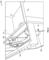
FIG. 8 depicts a first side view of a reversible reel system, according to examples. -
FIG. 9 depicts a second side view of a reversible reel system, according to examples. -
FIG. 10 depicts a third side view of a reversible reel system, according to examples. -
FIG. 11 depicts a fourth side view of a reversible reel system, according to examples. -
FIG. 12 depicts a perspective view of a reversible reel system, according to examples. - While various examples are amenable to various modifications and alternative forms, specifics thereof have been shown by way of example in the drawings and will be described in detail. It should be understood, however, that the intention is not to limit the claimed inventions to the particular examples described. On the contrary, the intention is to cover all modifications, equivalents, and alternatives falling within the spirit and scope of the subject matter of the present disclosure.
- Before turning to the FIGURES, which illustrate certain examples in detail, it should be understood that the present disclosure is not limited to the details or methodology set forth in the description or illustrated in the figures. It should also be understood that the terminology used herein is for the purpose of description only and should not be regarded as limiting.
- Referring generally to the FIGURES, a sprayhead hose retraction assembly (i.e., system) for use with faucet assemblies having a retractable spray head or hand spray is shown according to various examples. The faucet assembly generally includes a body, a spout, and a retractable sprayhead releasably coupled (e.g., removably coupled, selectively coupled, etc.) to the spout via a retractable hose. One or more hoses carry fluid through the spout from a mixing valve coupled to hot and cold waterlines to the sprayhead, where the fluid is dispensed (e.g., released, sprayed, output) to the environment, for example, into a basin, sink, tub, shower stall, etc.
- Referring to
FIGS. 1-3 , a sprayheadhose retraction system 100 for use with afaucet assembly 101 is shown, according to examples. Thefaucet assembly 101 andhose retraction system 100 is shown in a retracted (e.g., first, docked, retracted. etc.) position. In examples, thefaucet assembly 101 is shown to include abase 102, aspout 104, and asprayhead 106 removably coupled to (e.g., received in, engaging, etc.) thespout 104 via ahose 110 that extends within thefaucet assembly 101. Afirst end 110A of the hose is coupled to a mixing valve (not shown) positioned within the faucet, which is in turn coupled to a hot water inlet hose or flow line (not shown) and a cold water inlet hose or flow line (not shown), each of which are coupled to a source of hot water H inlet and a source of cold water C, respectively. - In the retracted position, the
sprayhead 106 may be coupled to and received in thespout 104. In examples, a sprayhead retraction system is configured to retract thesprayhead 106 from an extended position to the retracted position. Various examples of the sprayhead retraction assembly are described in greater detail below. Thefaucet assembly 101 is shown to include anarm 108 configured to house and support a manual or digital mixing valve (not shown). The valve may be configured to control the volume, temperature, or some combination thereof, of the fluid flow through thefaucet assembly 101 viahose 110. Ahandle 120 is coupled to the valve to control the operation thereof. According to other examples, thefaucet assembly 101 may not include anarm 108, and the valve and handle 120 may be located remotely from thefaucet 101. In examples, the faucet assembly may not include anarm 108 and handle 120 and may activate fluid flow through thefaucet assembly 101 by activating one or more touch sensors positioned at one or more locations on thebase 102,spout 104,sprayhead 106, etc. According to various other examples, thefaucet 101 may include an electronically controlled valve (e.g., solenoid valve) in addition to or instead of the manual valve. - In examples, the
faucet assembly 101 is operable with the sprayheadhose retraction system 100 to transition thesprayhead 106 between a retracted position and an extended position. In examples, thefaucet assembly 101 may include a fully extended position (e.g., a position in which thehose 110 may no longer be extended) and a plurality of partially extended positions (e.g., a position between the fully extended position and the retracted position). In some examples, the sprayheadhose retraction system 100 applies a force (e.g., constant force, variable force) to thehose 110 and thesprayhead 106 in the direction of the retracted position. Thus, if a user is using thesprayhead 106 in an extended position (e.g., a full or partially extended position), release of thesprayhead 106 by the user will result in thesprayhead 106 moving toward the retracted position and re-coupling with thespout 104. In examples, the transition of thesprayhead 106 between the retracted position and the extended position may be accomplished through the use of a pully/hose assembly 130 of the sprayheadhose retraction system 100. - In examples, the pully/
hose assembly 130 may include a plurality of pullies 134A-134B and aweighted pully 136 operably and rotatably coupled to a pully/hose assembly body ("body") 132. In examples, pullies 134A-134B may be coupled to thebody 132 viaattachable members 135 such that the pullies 134A-134B may remain secured to thebody 132 during operation, while maintaining rotational capability. Thebody 132 may be generally hollow in nature, while being structurally sound, and have a plurality of openings, forexample openings 150A-150B between uprights. In examples, theweighted pully 136 may be securely housed within theopenings 150A-150B of thebody 132. In examples, theweighted pully 136 may be configured to remain within thepully opening 150A, whereinmember openings 150B are configured to receiveslidable members 137 integrated with theweighted pully 136 such thatweighted pully 136 is axially slidable along opening 150A. - In examples, the plurality of pullies 134A-134B and
weighted pully 136 with defined grooves can be configured to receive thehose 110, at least in part. In examples, thehose 110 may be coupled to a plurality of pullies 134A-134B andweighted pully 136 such that movement of thehose 110 translates to movement of the pullies 134A-134B and 136, and vice versa. In examples, thehose 110 may be configured to be wrapped, at least partially, around thepullies 134A-134B and 136 such that, when thefaucet head 106 is in the retracted position, sections of thehose 110, such as first end 110a, are taut with thepullies 134A-134B and 136, while a second end 110b remains slack outside of thebody 132. In examples, when the faucet head is in the retracted position, theweighted pully 136 remains in an idle or stationary position (e.g., at the lowest position as depicted). - When a user pulls on the
sprayhead 106 to transition thesprayhead 106 out of the retracted position, thehose 110 is pulled through thespout 104 and about the plurality of pullies 134A-134B andweighted pully 136. In examples, when the user pulls thesprayhead 106, thehose 110 is pulled through, which rotates thepullies 134A-134B (e.g.,rotating pully 134A clockwise andpully 134B counterclockwise) and, in turn, lifts theweighted pully 136 vertically, thus, providing an extension of length of the hose for thesprayhead 106 out of thespout 104, previously held within the pully/hose assembly 130. The maximum length of extension is reached whenweighted pully 136 has reached the top of opening 150A. - When the user releases the
sprayhead 106, theweighted pully 136, no longer being held up by the user holding thesprayhead 106 in an extension position, theweighted pully 136 applies a downward force onto the hose 110 (e.g., due to gravity), which in turn pulls the hose back from thespout 104 and back into the pully/hose assembly 130, thus, transitioning thesprayhead 106 toward thespout 104. In examples, when thesprayhead 106 transitions between the retracted and extended positions, theweighted pully 136 may glide axially or vertically (e.g., up, and down betweenopening 150A, while theslidable members 137 may glide vertically withinmember openings 150B. In examples, thepullies 134A-134B may rotate about their center axis and be configured to guide the hose through the faucet assembly. It is to be understood that while three pullies are depicted, a variety of configurations are considered. In examples, greater or fewer number of pullies 134A-134B may be incorporated to compensate for the weight of theweighted pully 136, which would make transitioning thesprayhead 106 between the retracted and extended positions easier or more difficult. In examples, the hose remains taut to the pullies during transitions between the retracted and extended positions. - It will be understood that, while one side of the pully/
hose assembly 130 is being depicted, the opposite side is mirrored, such that thepully assembly 130 may be adaptable to either side of the faucet. In examples, the pully/hose assembly 130 may be reversible, such that the pully/hose assembly 130 may be rotatable about thebase 102 of the faucet and positioned to the opposite side of the faucet, rather than the side currently depicted. In examples, one or moreadjustable brackets 140A-140C may be integrated with the pully/hose assembly 130, such that the pully/hose assembly 130, pulleys 134A-134B,weighted pully 136, etc. may be secured (e.g., onto a wall, inside of a cabinet, below the faucet, behind the faucet, etc.). In examples, theadjustable bracket 140C, may be an adjustable foot or stand in which the pully/hose assembly 130, at least in part, rests. In examples, the pully/hose assembly 130 may be configured with abracket 154 which may hold and otherwise keep separate the hot, cold and tempered hose lines out of the way (e.g., between each other and other pieces that may cause interference with the normal functions of the pully/hose assembly 130). - In examples, the hose may include or otherwise incorporate a protruding knob 164 (more clearly depicted in
FIG. 2 ), either partially or completely surrounding the circumference of the hose. In examples, theknob 164 may be configured to have a diameter greater than the hose. Theknob 164 may be configured to prevent excess retraction of thehose 110 and limit downward momentum of theweighted pully 136 when thesprayhead 106 is transitioning into a complete retraction position. In examples, theknob 164 may retract until it catches on one of the brackets (e.g.,adjustable bracket 140B), of which thehose 110 may flow through, further preventing theweighted pully 136 from proceeding any further within the openings (i.e., as an additional precaution measure to limit the movement of theweighted pully 136 and prevent any damage to the faucet assembly 100). - In examples, a
reversible cover 160 may be configured to integrate with the pully/hose assembly 130. In examples, thereversible cover 160 may be shaped similarly to the design and implementation of the pullies 134A-134B,weighted pully 136 and thehose 110, such that thereversible cover 160 may overlap and protect the pully/hose assembly 130. In examples, knurled caps 162 may be integrated with thereversible cover 160 and may be configured to be attachable to the pully/hose assembly 130. In examples, the knurled caps 162 may screw onto and detach therefrom theattachment members 135 of the pullies 134A-134B and 136, for ease of access to the pully/hose assembly 130. It will be understood that while the pully/hose assembly 130 and thereversible cover 160 may be depicted as "L" shaped, alternative configurations and structures are contemplated to facilitate extension and retraction of thesprayhead 106. - In examples, the pully/
hose assembly 130 may be configured to connect to a mixing valve (not shown), such that, prior to entering the pully/hose assembly, mixed water (e.g., temperature regulated by the user, via the faucet arm/handle/etc.) has already been completed. Hot and cold water may be delivered from a hot fluid flow line and a cold fluid flow line (not shown) connected to hot water inlet H and cold water inlet C. In examples,pully assembly 130 is configured to be positioned within a same vertical plane asfaucet assembly 101 such that it is contained behind a sink basin and/or along a back wall of a sink cabinet. - Referring now to
FIGS. 4-6 , an alternative example of a sprayheadhose retraction system 200 is shown, according to examples.FIG. 4 depicts a standalone sink and faucet assembly including acabinet structure 202, one or more sink basins (not shown), a faucet base, a spout, a sprayhead removably coupled to (e.g., received in, engaging, etc.) the spout, and a drainage assembly. In examples, thecabinet structure 202 may include a housing or otherwise enclosed structure in which a pully/hose assembly 230 may be integrated. In examples, the existing structure of the faucet/sink may be leveraged. The sprayhead (not shown) may be operably coupled to ahose 110, as described above, having afirst end 110A connected to a mixing valve positioned within the faucet (not shown), and asecond end 110B operably coupled to the sprayhead (not shown). In the retracted position, the sprayhead may be coupled to and received in the spout. In examples, the sprayhead is configured to retract the sprayhead from an extended position to the retracted position via the pully/hose assembly 230 described in greater detail below. In examples, one or more adjustable legs may be integrated with the sink and faucet assembly to manage balance of the faucet assembly. - In examples, the faucet assembly is operable to transition the sprayhead between a retracted position and an extended position. In examples, the faucet assembly may include a fully extended position and a plurality of partially extended positions. In some examples, the retraction assembly applies a force (e.g., constant force, variable force) to the hose and the sprayhead in the direction of the retracted position. Thus, if a user is using the sprayhead in an extended position (e.g., a full or partially extended position), release of the sprayhead by the user will result in the sprayhead moving toward the retracted position and re-coupling with the spout. In examples, the transition of the sprayhead between the retracted position and the extended position may be accomplished through the use of a pully/
hose assembly 230, according to examples. -
FIG. 5 depicts the internal structure of a pully/hose assembly 230 within the housing of a sink and faucet assembly, according to examples. In examples, housed within thecabinet structure 202 may be the pully/hose assembly 230, including at least two pullies. In examples, the pullies may include aguide pully 234 and anadjacent tension pully 236 operably and rotatably coupled within the housing. In examples, thepullies hose 110, at least in part. In examples, thehose 110 may be coupled to thepullies hose 110 translates to movement of thepullies hose 110 may be configured to be wrapped, at least partially, around thepullies hose 110 are taut with thepullies hose 110 is pulled through the spout and about/aroundpully 234. In examples, when the user pulls the sprayhead, the movement of thehose 110 rotates thepullies 234 and 236 (e.g.,rotating pully 234 and tension pully 236 clockwise) and, in turn, pulls together thetension pully 236 closer to theguide pully 234. This provides an extension length ofhose 110 for the sprayhead out of the spout. - In examples, the
tension pully 236 may be configured to include a constant-force spring 238 therein. In examples, the constant-force spring 238 may be rotationally fixed to a position along the inner side walls of thehousing 202. The constant-force spring 238 provides an amount of tension on thetension pully 236 as the sprayhead transitions from the retracted position to the extended position. In examples, when the user releases the sprayhead, the stored energy from the stretched constant-force spring 238 is released and thetension pully 236 is rotated counterclockwise and returned to the original resting (i.e., the completely retracted) position. Thus, when the sprayhead transitions between the retracted and extended positions, thetension pully 236 may glide horizontally (e.g., from side to side) within thehousing 202. In examples, thepullies hose 110 through the faucet assembly. - It is to be understood while two pullies are depicted, a variety of configurations are considered. In examples, greater or fewer number of pullies may be incorporated to compensate for the weight of the
tension pully 236 or the amount of tension provided by the constant-force spring 238. In examples, the constant-force spring 238 may be joined to thetension pulley 236 in other ways (e.g., adhesive, weld, rivet, etc.). In examples, the constant-force spring 238 may be coiled such that it is configured to be uncoiled when thetension pully 236 moves toward therotating pully 234 as the sprayhead is undocked, transitioning from the retracted position to the extended position. The constant-force spring 238 provides a constant return force to the sprayhead regardless of how far the sprayhead is removed from the spout. In other words, the constant-force spring 238 provides a constant force to thetension pulley 236, regardless of the position of thetension pulley 236. With a traditional spring, the sprayhead would return to the spout more quickly or with more force the further it is withdrawn from the spout. In contrast to a traditional spring, the constant-force spring 238 does not respond differently the further it is withdrawn and provides the same tactile response for a user as a counterweight. - In examples, the pully/
hose assembly 230 may be configured to connect to a mixing valve, such that, prior to entering the pully/hose assembly 230, mixed water (e.g., temperature regulated by the user, via the faucet arm/handle/etc.) has already been completed. In examples, a mixed water coupling may be secured to the faucet assembly or the pully/hose assembly 230 to a hose extension. - Referring to
FIG. 6 , the second end 110b ofhose 110 that is connected to the mixing valve, is coupled toassembly 230 via acoupling 240 secured to thehousing 202. An extension of remaininghose 110 is then limited by coupling 240 to prevent overextension ofhose 110, which can otherwise result in decoupling offirst end 110A of thehose 110 from the mixing valve. - As depicted in
FIG. 6 ,assembly 230 lies in a same plane as the faucet assembly, and behind a sink basin B, such thathose 110 does not interfere with components underneath basin B. - Referring now to
FIGS. 7-12 , an alternative sprayheadhose retraction system 300 forfaucet assembly 101 is shown, according to examples.FIG. 7 depicts afaucet assembly 101 with similarly depicted faucet components as previously described, such as one or more sink basins B, being operably coupled, the faucet assembly including a faucet base, a spout, and a sprayhead removably coupled to (e.g., received in, engaging, etc.) the spout, etc. The sprayhead may be operably coupled to a hose configured to be extractable and retractable. In the retracted position, the sprayhead may be coupled to and received in the spout. In examples, the reversible reel system may be configured to retract the sprayhead from an extended position to the retracted position via an internal constant-force clock spring described in greater detail below. - Referring to
FIGS. 8-12 , thereversible reel system 302 including asingle reel 304 may be secured below the faucet (e.g., within the housing) with a bracket structure 306 (e.g., a stamped steel bracket) such that thereversible reel system 302 may be self-calibrated when secured. Thereversible reel system 302 may be installed on either side (i.e., left or right) of the faucet. In examples, thereversible reel 304 may include structure defining a groove running the external edges and configured to receive a length ofhose 110. In examples, thehose 110 may be wrapped around thereversible reel 304, within the groove. Thereversible reel 304 is configured to be rotatable about its center axis, as depicted. In examples, thereversible reel system 302 may be adapted to a range of hose lengths and sizes, while maximizing hand spray reach (i.e., the greater amount of hose wrapped around thereversible reel system 302, the greater amount of hose may be extended). In examples, thereversible reel 304 may be configured with a rotating O-ring sealedjunction 309 which allows the reel to spin freely while maintaining a water seal. - In examples, the
reversible reel system 302 is operable to transition the sprayhead between a retracted position and an extended position. In examples, thereversible reel system 302 may include a fully extended position (e.g., a position in which thehose 110 may no longer be extended) and a plurality of partially extended positions (e.g., a position between the fully extended position and the retracted position). As the user transitions the sprayhead into an extended position, thehose 110 extends out of the spout and is unwrapped from thereversible reel 304, out of the groove. In some examples, thereversible reel 304 may include an internal constant-force clock spring (not shown) that applies a force (e.g., constant force, variable force) to thehose 110 and the sprayhead in the direction of the retracted position, as described previously. Thus, if a user is using the sprayhead in an extended position (e.g., a full or partially extended position), release of the sprayhead by the user will result in the sprayhead transitioning toward the retracted position and re-coupling with the spout. As the sprayhead returns to the retracted position, thehose 110 continues to re-wrap around thereversible reel 304 within the groove. Thereversible reel system 302 improves capacity under thefaucet assembly 101, and adapts to a wide range of hose lengths and limits the number of moving pieces while maximizing the amount of extension length available for the sprayhead. - With additional reference to
FIGS. 8 and12 , in examples, thereversible reel system 302 may be configured to connect to a mixing valve (not shown) positioned within the faucet assembly, such that, prior to entering thereversible reel system 302, mixed fluid (e.g., temperature regulated by the user, via the faucet arm/handle/etc.) has already been completed. In examples, mixed fluid may enter through ashort hose 312 andrigid conduit 314 adapting thereel 304 to thefaucet assembly 101, and flow through the hose (i.e., around thereversal reel system 302 if the hose is currently wrapped) and out of the sprayhead of the faucet. In examples, aconnector 310 on theextension hose 110 may be incorporated such that the faucet may click or otherwise snap into thereversible reel system 302. Theconnector 310 provides easy installation and fluid connectivity. In examples, the connector detail of theconnector 310 of thereel 304 matches a connector detail on a connector C of the faucet, such that thereversible reel system 302 can be retrofitted into an existing faucet or taken out. In examples, the geometry of thereversible reel system 302 may manage the long endpieces on pull-out spray faucets for easier installation. - It should be understood that the individual operations used in the methods of the present teachings may be performed in any order and/or simultaneously, as long as the teaching remains operable. Furthermore, it should be understood that the apparatus and methods of the present teachings can include any number, or all, of the described examples, as long as the teaching remains operable.
- Various examples of systems, devices, and methods have been described herein. These examples are given only by way of example and are not intended to limit the scope of the claimed inventions. It should be appreciated, moreover, that the various features of the examples that have been described may be combined in various ways to produce numerous additional examples. Moreover, while various materials, dimensions, shapes, configurations and locations, etc. have been described for use with disclosed examples, others besides those disclosed may be utilized without exceeding the scope of this disclosure.
- Persons of ordinary skill in the relevant arts will recognize that the subject matter hereof may comprise fewer features than illustrated in any individual example described above. The examples described herein are not meant to be an exhaustive presentation of the ways in which the various features of the subject matter hereof may be combined. Accordingly, the examples are not mutually exclusive combinations of features; rather, the various examples can comprise a combination of different individual features selected from different individual examples, as understood by persons of ordinary skill in the art. Moreover, elements described with respect to one example can be implemented in other examples even when not described in such examples unless otherwise noted.
- Although a dependent claim may refer in the claims to a specific combination with one or more other claims, other examples can also include a combination of the dependent claim with the subject matter of each other dependent claim or a combination of one or more features with other dependent or independent claims. Such combinations are proposed herein unless it is stated that a specific combination is not intended.
- Any incorporation by reference of documents above is limited such that no subject matter is incorporated that is contrary to the explicit disclosure herein. Any incorporation by reference of documents above is further limited such that no claims included in the documents are incorporated by reference herein. Any incorporation by reference of documents above is yet further limited such that any definitions provided in the documents are not incorporated by reference herein unless expressly included herein.
- For purposes of interpreting the claims, it is expressly intended that the provisions of 35 U.S.C. 9 112(f) are not to be invoked unless the specific terms "means for" or "step for" are recited in a claim.
Claims (15)
- A retractable sprayhead hose management system, comprising:a faucet including a sprayhead;a hose coupled to the sprayhead;a hose assembly body coupled to the faucet; anda pully assembly including one or more first pullies coupled to a second pully, wherein the one or more first pullies are coupled to the hose assembly body while maintaining rotational capability during operation,wherein the hose wraps around the second pully such that outward extension of the sprayhead tightens the hose around the one or more first pullies and the second pully, the second pully being lifted as the sprayhead extends outward, the second pully providing a force onto the hose which enables the second pully to retract the sprayhead inward.
- The retractable sprayhead hose management system of claim 1, wherein the second pully is housed within one or more openings defined in the hose assembly body, such that the second pully is enabled to move vertically along the hose assembly body.
- The retractable sprayhead hose management system of claim 1 or claim 2, wherein the sprayhead is configured to transition between a retracted position and one or more extended positions.
- The retractable sprayhead hose management system of claim 1, claim 2 or claim 3, wherein when the sprayhead is retracted inward, a first portion of the hose is taut with the second pully and at least one of the one or more first pullies, and a second portion of the hose is slack with the second pully and at least one of the one or more first pullies.
- The retractable sprayhead hose management system of any one of claims 1 to 4, wherein extension of the sprayhead rotates the one or more first pullies which enables lifting of the second pully along an opening defined in the hose assembly body and/or wherein inward retraction of the sprayhead enables the second pully to return to a lower lifted position or an unlifted position.
- The retractable sprayhead hose management system of any one of claims 1 to 5, wherein the hose assembly body comprises a protruding knob configured to limit downward momentum of the second pully as the sprayhead retracts inward.
- A retractable sprayhead hose management system, comprising:a faucet including a sprayhead;a hose coupled to the sprayhead;a pully assembly including a first pully coupled to a second pully, the first pully and the second pully being coupled to the hose; anda spring coupled to the second pully,wherein the hose wraps around the second pully such that outward extension of the sprayhead tightens the hose around the first pully and the second pully, wherein the second pully is configured to tension the spring during outward extension of the sprayhead, such that release of the tension between the second pully and the spring enables the second pully to retract the sprayhead inward.
- The retractable sprayhead hose management system of claim 7, wherein the spring is a constant-force spring configured to provide a constant force to the second pully irrespective of the position of the second pully.
- The retractable sprayhead hose management system of claim 7 or claim 8, wherein the sprayhead is configured to transition between a retracted position and one or more extended positions.
- The retractable sprayhead hose management system of claim 7, claim 8 or claim 9, wherein when the sprayhead is retracted inward, a first portion of the hose is taut with the first pully and the second pully, and a second portion of the hose is slack with the first pully and the second pully.
- The retractable sprayhead hose management system of any one of claims 7 to 10, wherein the pully assembly is received within a cabinet structure.
- A reversible reel system, comprising:a faucet including a sprayhead;a hose coupled to the sprayhead; anda reel positioned below the faucet, the reel configured to receive a portion of the hose, wherein the reel is configured to transition the sprayhead between one or more extended positions and a retracted position, the reel including a spring configured to apply a force to the hose in the direction of the retracted position.
- The reversible reel system of claim 12, wherein the spring is an internal constant-force clock spring configured to, upon release of a force applied to the hose in the direction of the retracted position, retract the sprayhead inward.
- The retractable sprayhead hose management system of any one of claims 1 to 11 or the reversible reel system of claim 12 or claim 13, wherein the hose defines a first end and a second end, the first end being coupled to the sprayhead of the faucet, the second end being coupled to a fluid mixing valve positioned within the faucet.
- The reversible reel system of claim 12, claim 13 or claim 14, wherein the reel defines a groove along an external reel edge, the groove configured to receive a portion of the hose and/or wherein the reel is secured below the faucet via a bracket structure such that the reversible reel system can be self-calibrated and/or wherein the reel is configured to be rotatable about a reel center axis.
Applications Claiming Priority (2)
| Application Number | Priority Date | Filing Date | Title |
|---|---|---|---|
| US202363489382P | 2023-03-09 | 2023-03-09 | |
| US18/582,178 US20240301670A1 (en) | 2023-03-09 | 2024-02-20 | Retractable hose management system |
Publications (1)
| Publication Number | Publication Date |
|---|---|
| EP4428312A1 true EP4428312A1 (en) | 2024-09-11 |
Family
ID=90363797
Family Applications (1)
| Application Number | Title | Priority Date | Filing Date |
|---|---|---|---|
| EP24162042.6A Pending EP4428312A1 (en) | 2023-03-09 | 2024-03-07 | Retractable hose management system |
Country Status (2)
| Country | Link |
|---|---|
| US (1) | US20240301670A1 (en) |
| EP (1) | EP4428312A1 (en) |
Families Citing this family (8)
| Publication number | Priority date | Publication date | Assignee | Title |
|---|---|---|---|---|
| US20240344305A1 (en) * | 2021-09-17 | 2024-10-17 | Assa Abloy Americas Residential Inc. | Retractable spray head faucet with dampened retraction feature |
| USD1114188S1 (en) * | 2024-12-19 | 2026-02-17 | Xiamen Lota International Co., Ltd. | Faucet kit |
| USD1125470S1 (en) * | 2024-12-19 | 2026-05-05 | Xiamen Lota International Co., Ltd. | Faucet kit |
| USD1123106S1 (en) * | 2025-01-16 | 2026-04-21 | Clement Inc. | Basin faucet |
| USD1123110S1 (en) * | 2025-02-18 | 2026-04-21 | Delta Faucet Company | Faucet |
| USD1123107S1 (en) * | 2025-02-18 | 2026-04-21 | Delta Faucet Company | Faucet |
| USD1124256S1 (en) * | 2025-02-18 | 2026-04-28 | Delta Faucet Company | Faucet |
| USD1117643S1 (en) * | 2025-02-20 | 2026-03-10 | Guangdong Yawei Sanitary Ware Technology Co., Ltd | Faucet |
Citations (12)
| Publication number | Priority date | Publication date | Assignee | Title |
|---|---|---|---|---|
| US2168951A (en) * | 1937-01-11 | 1939-08-08 | Caldwell William Taylor | Flexible service tube or hose housing |
| AT193320B (en) * | 1955-06-29 | 1957-11-25 | Walter Dipl Ing Fischer | Bracket for the supply hose to a shower head |
| US5117859A (en) * | 1990-11-19 | 1992-06-02 | Elden Barbieri | Flexible hose retractor |
| WO2004081437A2 (en) * | 2003-03-12 | 2004-09-23 | Masco | Faucet spray head hose guide and retraction mechanism |
| DE102012205417A1 (en) * | 2012-04-03 | 2013-10-10 | Hansgrohe Se | Sanitary fitting e.g. surface mounted fitting for attaching to e.g. wash basin, has water channel whose shower hose is rolled up in hose cassette and arranged on/in base body such that water channel guides from base body into cassette |
| WO2017108613A1 (en) * | 2015-12-22 | 2017-06-29 | Hansgrohe Se | Hose guide device and sanitary pull-out-hose fitting |
| US20170356170A1 (en) * | 2016-06-13 | 2017-12-14 | Kohler Co. | Sprayhead retraction assembly |
| WO2018148035A1 (en) * | 2017-02-10 | 2018-08-16 | Leipold John | Kitchen sink hose reel |
| WO2021191609A1 (en) * | 2020-03-27 | 2021-09-30 | G3 Services Ltd | Retracting shower hose apparatus and method |
| IT202000015412A1 (en) * | 2020-06-26 | 2021-12-26 | Ceadesign Srl | REEL-UNREEL DEVICE FOR FLEXIBLE HOSES |
| US20210404156A1 (en) * | 2018-08-23 | 2021-12-30 | Spectrum Brands, Inc. | Faucet spray head alignment system |
| WO2022226854A1 (en) * | 2021-04-28 | 2022-11-03 | Kohler Co. | Spray head retraction assembly |
Family Cites Families (3)
| Publication number | Priority date | Publication date | Assignee | Title |
|---|---|---|---|---|
| US6296011B1 (en) * | 1999-04-14 | 2001-10-02 | Kohler Co. | Fluid valve |
| US20160237661A1 (en) * | 2015-02-13 | 2016-08-18 | Bruce Teagarden | Hidden Extendable and Retractable Shower Hose System |
| US12168862B2 (en) * | 2021-04-28 | 2024-12-17 | Kohler Co. | Spray head retraction assembly |
-
2024
- 2024-02-20 US US18/582,178 patent/US20240301670A1/en active Pending
- 2024-03-07 EP EP24162042.6A patent/EP4428312A1/en active Pending
Patent Citations (12)
| Publication number | Priority date | Publication date | Assignee | Title |
|---|---|---|---|---|
| US2168951A (en) * | 1937-01-11 | 1939-08-08 | Caldwell William Taylor | Flexible service tube or hose housing |
| AT193320B (en) * | 1955-06-29 | 1957-11-25 | Walter Dipl Ing Fischer | Bracket for the supply hose to a shower head |
| US5117859A (en) * | 1990-11-19 | 1992-06-02 | Elden Barbieri | Flexible hose retractor |
| WO2004081437A2 (en) * | 2003-03-12 | 2004-09-23 | Masco | Faucet spray head hose guide and retraction mechanism |
| DE102012205417A1 (en) * | 2012-04-03 | 2013-10-10 | Hansgrohe Se | Sanitary fitting e.g. surface mounted fitting for attaching to e.g. wash basin, has water channel whose shower hose is rolled up in hose cassette and arranged on/in base body such that water channel guides from base body into cassette |
| WO2017108613A1 (en) * | 2015-12-22 | 2017-06-29 | Hansgrohe Se | Hose guide device and sanitary pull-out-hose fitting |
| US20170356170A1 (en) * | 2016-06-13 | 2017-12-14 | Kohler Co. | Sprayhead retraction assembly |
| WO2018148035A1 (en) * | 2017-02-10 | 2018-08-16 | Leipold John | Kitchen sink hose reel |
| US20210404156A1 (en) * | 2018-08-23 | 2021-12-30 | Spectrum Brands, Inc. | Faucet spray head alignment system |
| WO2021191609A1 (en) * | 2020-03-27 | 2021-09-30 | G3 Services Ltd | Retracting shower hose apparatus and method |
| IT202000015412A1 (en) * | 2020-06-26 | 2021-12-26 | Ceadesign Srl | REEL-UNREEL DEVICE FOR FLEXIBLE HOSES |
| WO2022226854A1 (en) * | 2021-04-28 | 2022-11-03 | Kohler Co. | Spray head retraction assembly |
Also Published As
| Publication number | Publication date |
|---|---|
| US20240301670A1 (en) | 2024-09-12 |
Similar Documents
| Publication | Publication Date | Title |
|---|---|---|
| US20240301670A1 (en) | Retractable hose management system | |
| US10106963B2 (en) | Sprayhead retraction assembly | |
| US20240344305A1 (en) | Retractable spray head faucet with dampened retraction feature | |
| CN108290702B (en) | Pulling out leading hose retraction system and method | |
| US10695786B2 (en) | Hand-held shower head system | |
| US20240125101A1 (en) | Shower systems | |
| US20250075474A1 (en) | Spray head retraction assembly | |
| WO2016210178A1 (en) | Adjustable height shower apparatus having multiple shower sprayers | |
| CN110656681B (en) | Suspended Handheld Shower Stand | |
| CN106132260A (en) | Shelving system with concealable shelves | |
| US20220364340A1 (en) | Soft-close spray head faucet | |
| WO2022226854A1 (en) | Spray head retraction assembly | |
| ES3038741T3 (en) | Sanitary washstand or sink unit | |
| CN118621871A (en) | Retractable hose management system | |
| US2707467A (en) | Reel unit for douche apparatus | |
| US10287758B2 (en) | Adjustable height shower apparatus | |
| WO2022227812A1 (en) | Spray head retraction assembly | |
| JP4308418B2 (en) | Hose storage faucet | |
| WO2024173988A1 (en) | A hose management system | |
| CN222477636U (en) | Retractable shower equipment and faucet equipment | |
| JPH0514262U (en) | Shower device | |
| CN221982732U (en) | Shower head | |
| AU2014101148A4 (en) | Extension and retraction assembly | |
| JP2004229842A (en) | Shower hose housing device | |
| AU2012202116A1 (en) | Shower arrangement |
Legal Events
| Date | Code | Title | Description |
|---|---|---|---|
| PUAI | Public reference made under article 153(3) epc to a published international application that has entered the european phase |
Free format text: ORIGINAL CODE: 0009012 |
|
| STAA | Information on the status of an ep patent application or granted ep patent |
Free format text: STATUS: THE APPLICATION HAS BEEN PUBLISHED |
|
| AK | Designated contracting states |
Kind code of ref document: A1 Designated state(s): AL AT BE BG CH CY CZ DE DK EE ES FI FR GB GR HR HU IE IS IT LI LT LU LV MC ME MK MT NL NO PL PT RO RS SE SI SK SM TR |
|
| STAA | Information on the status of an ep patent application or granted ep patent |
Free format text: STATUS: REQUEST FOR EXAMINATION WAS MADE |
|
| 17P | Request for examination filed |
Effective date: 20250310 |