EP4428304A1 - Material collection equipment and spoiler - Google Patents
Material collection equipment and spoiler Download PDFInfo
- Publication number
- EP4428304A1 EP4428304A1 EP23160465.3A EP23160465A EP4428304A1 EP 4428304 A1 EP4428304 A1 EP 4428304A1 EP 23160465 A EP23160465 A EP 23160465A EP 4428304 A1 EP4428304 A1 EP 4428304A1
- Authority
- EP
- European Patent Office
- Prior art keywords
- spoiler
- implement
- compartment
- collection equipment
- material collection
- Prior art date
- Legal status (The legal status is an assumption and is not a legal conclusion. Google has not performed a legal analysis and makes no representation as to the accuracy of the status listed.)
- Pending
Links
Images






Classifications
-
- E—FIXED CONSTRUCTIONS
- E01—CONSTRUCTION OF ROADS, RAILWAYS, OR BRIDGES
- E01H—STREET CLEANING; CLEANING OF PERMANENT WAYS; CLEANING BEACHES; DISPERSING OR PREVENTING FOG IN GENERAL CLEANING STREET OR RAILWAY FURNITURE OR TUNNEL WALLS
- E01H1/00—Removing undesirable matter from roads or like surfaces, with or without moistening of the surface
- E01H1/12—Hand implements, e.g. litter pickers
-
- E—FIXED CONSTRUCTIONS
- E01—CONSTRUCTION OF ROADS, RAILWAYS, OR BRIDGES
- E01H—STREET CLEANING; CLEANING OF PERMANENT WAYS; CLEANING BEACHES; DISPERSING OR PREVENTING FOG IN GENERAL CLEANING STREET OR RAILWAY FURNITURE OR TUNNEL WALLS
- E01H1/00—Removing undesirable matter from roads or like surfaces, with or without moistening of the surface
- E01H1/02—Brushing apparatus, e.g. with auxiliary instruments for mechanically loosening dirt
- E01H1/04—Brushing apparatus, e.g. with auxiliary instruments for mechanically loosening dirt taking- up the sweepings, e.g. for collecting, for loading
-
- E—FIXED CONSTRUCTIONS
- E01—CONSTRUCTION OF ROADS, RAILWAYS, OR BRIDGES
- E01H—STREET CLEANING; CLEANING OF PERMANENT WAYS; CLEANING BEACHES; DISPERSING OR PREVENTING FOG IN GENERAL CLEANING STREET OR RAILWAY FURNITURE OR TUNNEL WALLS
- E01H1/00—Removing undesirable matter from roads or like surfaces, with or without moistening of the surface
- E01H1/02—Brushing apparatus, e.g. with auxiliary instruments for mechanically loosening dirt
- E01H1/04—Brushing apparatus, e.g. with auxiliary instruments for mechanically loosening dirt taking- up the sweepings, e.g. for collecting, for loading
- E01H1/045—Brushing apparatus, e.g. with auxiliary instruments for mechanically loosening dirt taking- up the sweepings, e.g. for collecting, for loading the loading means being a rotating brush with horizontal axis
-
- E—FIXED CONSTRUCTIONS
- E01—CONSTRUCTION OF ROADS, RAILWAYS, OR BRIDGES
- E01H—STREET CLEANING; CLEANING OF PERMANENT WAYS; CLEANING BEACHES; DISPERSING OR PREVENTING FOG IN GENERAL CLEANING STREET OR RAILWAY FURNITURE OR TUNNEL WALLS
- E01H1/00—Removing undesirable matter from roads or like surfaces, with or without moistening of the surface
- E01H1/02—Brushing apparatus, e.g. with auxiliary instruments for mechanically loosening dirt
- E01H1/04—Brushing apparatus, e.g. with auxiliary instruments for mechanically loosening dirt taking- up the sweepings, e.g. for collecting, for loading
- E01H1/047—Collecting apparatus characterised by the hopper or by means for unloading the hopper
-
- E—FIXED CONSTRUCTIONS
- E01—CONSTRUCTION OF ROADS, RAILWAYS, OR BRIDGES
- E01H—STREET CLEANING; CLEANING OF PERMANENT WAYS; CLEANING BEACHES; DISPERSING OR PREVENTING FOG IN GENERAL CLEANING STREET OR RAILWAY FURNITURE OR TUNNEL WALLS
- E01H1/00—Removing undesirable matter from roads or like surfaces, with or without moistening of the surface
- E01H1/12—Hand implements, e.g. litter pickers
- E01H2001/122—Details
- E01H2001/1226—Details characterised by way of removing material
- E01H2001/1246—Double or multiple closing means making horizontal sliding movement (not applied for grabs)
Definitions
- the present disclosure relates to a material collection equipment, and more particularly, to a spoiler for the material collection equipment.
- Hand-held material collection equipment including, but not limited to, mobile garden tools, such as leaf collecting devices (e.g., lawn sweepers, leaf sweepers, etc.) and lawn movers have been well known in the art.
- Such tools typically include an implement portion, a storage compartment in communication with the implement portion, and a handle connected to the implement portion and/or the storage compartment.
- the implement portion may collect and transfer leaf or any other object from a ground surface on which the tool is working to the storage compartment.
- a lower front edge of the implement portion may exhibit a free space towards the ground surface.
- Some tools may be designed to run on grass and collect the leaves lying on the surface of the grass.
- the free space can be large in such cases since wheels of the tool run on the ground surface while the leaves are on top of the surface of the grass. If such tools are utilized on surfaces such as paved surfaces or concrete to sweep away the leaves, the large free space may result in a lot of dirt and dust disappearing out of the implement department.
- EP 3 765 675 B 1 An example of such a tool is disclosed in EP 3 765 675 B 1.
- the '675 reference describes a material collection equipment that includes a handle, a storage compartment, an implement compartment, an axle, and a pair of wheels.
- the material collection equipment further includes an implement adapted to collect material from a ground surface and transfer the material into the storage compartment.
- the objective is at least partially achieved by a material collection equipment that may allow a user to easily manipulate a free space between a front lower edge of the material collection equipment and a ground surface.
- the material collection equipment includes a handle extending along a first axis.
- the material collection equipment further includes a connection element connecting the handle with an implement compartment.
- the implement compartment defines a lower front edge along a second axis away from the handle.
- the second axis extends transversely relative to the first axis.
- the material collection equipment further includes an implement disposed within the implement compartment and adapted to collect a material from a ground surface and to transfer the material into a storage compartment.
- the material collection equipment further includes a pair of wheels. Each wheel from the pair of wheels is rotatably coupled to the implement compartment through a respective axle.
- Each wheel includes a running surface.
- Each wheel defines a spoiler direction from the respective axle towards a mid of the respective running surface.
- the material collection equipment is characterized in that a spoiler is coupled to the implement compartment to extend the lower front edge of the implement compartment along the spoiler direction.
- the spoiler is disposed adjacent to the lower front edge of the implement compartment.
- the spoiler is toollessly adjusted along the spoiler direction relative to the implement compartment in a form-fit manner to extend the lower front edge.
- the material collection equipment of the present disclosure includes the spoiler coupled to the implement compartment and disposed adjacent to the front lower edge of the implement compartment.
- the spoiler may allow a user of the material collection equipment to extend the lower front edge of the implement compartment, thereby enabling easy manipulation of a free space between the front lower edge of the implement compartment and the ground surface. This may mitigate dirt and dust disappearing out of the implement department when working on surfaces such as paved surfaces, concrete, etc.
- the spoiler may operate as a flexible curtain that prevents the material (e.g., leaves, branches, etc.) from being thrown forward by the implement out of the range of the implement. Therefore, the material may be constrained by the spoiler and eventually picked up by the implement.
- the spoiler of the present disclosure may improve a collection performance of the material collection equipment even on ground surfaces such as paved surfaces, concrete, etc. as well as on low cut lawns. This may mitigate the need for multiple operational cycles with the material collection equipment on the same surface to collect the material.
- the spoiler of the present disclosure may be toollessly adjusted along the spoiler direction relative to the implement compartment in the form-fit manner.
- the spoiler may not require any additional tools for adjusting the spoiler relative to the implement compartment, thereby promoting user-friendliness and ease of using the spoiler.
- the lower front edge may be adjusted starting from a maximum distance from the running surface.
- the spoiler of the present disclosure is disposed at a front of the implement compartment. Therefore, the spoiler may not negatively impact a performance of the material collection equipment on the regular working surfaces and in a parking position of the material collection equipment. Further, the spoiler of the present disclosure is light-weighted and flexible, thereby allowing the spoiler to move over the material to be collected without pushing the material.
- the spoiler is pivotally coupled to the implement compartment.
- the user may be able to manipulate the spoiler based on operational requirements and a type of the ground surface to be worked upon.
- the spoiler includes a rigid holding member extending along the second axis and pivotally coupled to the implement compartment.
- the spoiler further includes a flexible member extending from the rigid holding member away from the implement compartment.
- the flexible member defines a proximal edge disposed adjacent to the rigid holding member and a distal edge spaced apart from the proximal edge away from the rigid holding member.
- the flexible member further defines an extending direction from the proximal edge of the flexible member towards the distal edge of the flexible member.
- the rigid holding member may allow the spoiler to be pivotally coupled to the implement compartment in a safe and reliable manner while the flexible member may allow the spoiler to move over the material to be collected without pushing or damaging it. Further, the rigid holding member may be pivotally coupled to the implement compartment in the form-fit manner.
- the rigid holding member may be made of a plastic material that may be light weight.
- the flexible member may be made of a polymeric material, such as rubber.
- the spoiler is pivotable relative to the implement compartment between an operational position and a storage position.
- the extending direction of the flexible member In the operational position, the extending direction of the flexible member is substantially along the spoiler direction, and in the storage position, the extending direction of the flexible member is substantially opposite to the spoiler direction.
- the spoiler may be pivoted based on the operational requirements and the type of the ground surface to be worked upon. For example, the spoiler may be pivoted to the storage position in case the spoiler is no longer required, e.g., when working on long grass surfaces. Further, in the operational position, the distal edge of the flexible member may be disposed closer to the ground surface, thereby reducing any free space between the front lower edge of the implement compartment and the ground surface. According to an exemplary embodiment of the invention, the spoiler may be held at any intermediate position between the operational position and the storage position. Further, the spoiler may be toollessly adjusted (or moved between the operational position and the storage position) along the spoiler direction relative to the implement compartment in the form-fit manner, thereby retaining the spoiler at any of the intermediate positions.
- the spoiler may be pivotable to any position between the operational position and the storage position, thereby allowing the user to easily manipulate the free space between the front lower edge of the implement compartment and the ground surface.
- the material collection equipment further includes at least one connecting member fixedly coupled to the implement compartment and defining a connecting surface facing the spoiler.
- the rigid holding member is pivotally coupled to the connecting surface of the at least one connecting member.
- the connecting member may allow the rigid holding member of the spoiler to be reliably secured to the implement compartment.
- the at least one connecting member may be fixedly coupled to the implement compartment through any suitable coupling mechanisms, including, but not limited to, fasteners, adhesives, snap-fit connections, tongue and groove joints, etc.
- the spoiler further includes at least one flexible locking member coupled to and extending from the rigid holding member adjacent to the at least one connecting member.
- the at least one flexible locking member In the storage position, the at least one flexible locking member is adapted to lockingly and releasably engage with the connecting surface of the at least one connecting member, such that the spoiler is restricted from pivoting relative to the implement compartment.
- the at least one flexible locking member In the operational position, the at least one flexible locking member is disengaged from the connecting surface of the at least one connecting member.
- the at least one flexible locking member may allow the spoiler to be retained in the storage position when the spoiler is not required during operation of the material collection equipment.
- the at least one flexible locking member may include a flexible shape that may be released from the connecting surface upon application of a force as the spoiler is pivoted to the operational position from the storage position.
- the at least one flexible locking member may be flexible to be able to be released from the connecting surface when required but stable enough to hold the spoiler in the storage position.
- the at least one flexible locking member is in the form of a loop allowing the at least one flexible locking member to flex and get released from the connecting surface of the at least one connecting member upon movement of the spoiler from the storage position to the operational position.
- the at least one flexible locking member may be made of a polymeric material, such as plastic.
- the spoiler further includes at least one slot.
- the at least one slot extends from the distal edge of the flexible member at least partially towards the proximal edge of the flexible member.
- the at least one slot may divide the spoiler into a plurality of flexible latches, thereby enhancing the flexibility of the spoiler to slide over solid obstacles without getting damaged.
- the at least one slot includes a plurality of slots.
- Each slot from the plurality of slots extends from the distal edge at least partially towards the proximal edge.
- the plurality of slots may divide the spoiler into multiple flexible latches, thereby further enhancing the flexibility of the spoiler.
- some of the plurality of slots may have a varying length.
- the spoiler may have a variable stiffness at different locations.
- the spoiler is removably coupled to the implement compartment.
- the spoiler may be easily removed when not required and in storage position.
- the spoiler may be retrofitted to existing material collection equipment.
- the spoiler may be sold as an aftermarket accessory.
- the spoiler may be replaced upon wear and tear since the spoiler is removably coupled to the implement compartment.
- the spoiler includes a rigid holding member extending along the second axis and removably coupled to the implement compartment.
- the spoiler further includes a flexible member extending from the rigid holding member away from the implement compartment.
- the flexible member defines a distal edge away from the rigid holding member.
- the rigid holding member may allow the spoiler to be pivotally coupled to the implement compartment in a safe and reliable manner while the flexible member may allow the spoiler to move over the material to be collected without pushing or damaging it.
- the spoiler is removably coupled to the implement compartment between a first position and a second position.
- a distance between the distal edge of the flexible member and the running surface of each wheel along the spoiler direction in the first position is greater than a distance between the distal edge and the running surface of each wheel along the spoiler direction in the second position.
- the distance between the distal edge of the flexible member and the running surface of each wheel along the spoiler direction may be varied based on the type of ground surface and application requirements.
- the spoiler may be toollessly removed from the first position and again coupled to the material collection equipment in the second position for varying the distance between the distal edge of the flexible member and the running surface of each wheel along the spoiler direction.
- the material collection equipment further includes at least one securing member removably coupling the spoiler to the implement compartment.
- the implement compartment includes at least one receiving portion disposed adjacent to the lower front edge.
- the at least one securing member includes an elongated portion.
- the at least one securing member further includes a projection extending transversely from the elongated portion and adapted to engage with walls (e.g., a groove within the walls) of the corresponding receiving portion.
- the elongated portion is adapted to be at least partially received through the corresponding receiving portion.
- the at least one securing member may be rotated after inserting the elongated portion into the corresponding receiving portion, thereby allowing the projection to engage with the walls of the corresponding receiving portion.
- the at least one securing member may secure the spoiler to the implement compartment in the form-fir manner.
- the spoiler includes an elastic member extending along the second axis and removably coupled to the implement compartment.
- the spoiler further includes a flexible member extending from the elastic member away from the implement compartment.
- An elasticity of the flexible member is different from an elasticity of the elastic member.
- the flexible member defines a distal edge away from the elastic member.
- the elastic member may allow the spoiler to be removably coupled to the implement compartment in a safe and reliable manner.
- the elastic member may be coupled to the implement compartment at both its ends.
- the flexible member may allow the spoiler to move over the material to be collected without pushing or damaging it.
- the elastic member may be less elastic than the flexible member and may act as an expander.
- the material collection equipment further includes at least one rib disposed along a side wall of the implement compartment.
- the material collection equipment further includes at least one engaging member corresponding to the at least one rib.
- the at least one engaging member is fixedly coupled to the elastic member.
- the at least one engaging member removably engages with the at least one rib, such that the spoiler is removably coupled to the implement compartment.
- the at least one engaging member may allow the spoiler to be removably coupled to the implement compartment. Further, the at least one engaging member may allow the spoiler to be suitably positioned relative to the at least one rib of the implement compartment, thereby enabling varying positions for the spoiler. For example, the spoiler may be positioned away from the lower front edge of the implement compartment during storage of the material collection equipment.
- the at least one rib may include an opening adapted to receive at least a portion of the at least one engaging member for removably coupling the spoiler to the implement compartment.
- the opening may allow the at least one engaging member to be secured to the implement compartment in a reliable manner.
- the at least one rib may include a plurality of indents spaced apart from each other.
- the plurality of indents may allow the spoiler to be correctly positioned relative to the implement compartment.
- the at least one engaging member may be in the form of a hook or any other suitable holding means.
- the hook may allow the user to easily remove and attached the spoiler to the at least one rib of the implement compartment.
- the spoiler further includes a holding member for allowing the user to secure the at least one engaging member to the at least one rib.
- the holding member is secured to the at least one engaging member via at least one protrusion extending from the holding member.
- the at least one protrusion is at least partially received through the elastic member and the at least one engaging member, thereby allowing the holding member to be secured to the at least one engaging member.
- the holding member may allow the user to apply a force on the at least one engaging member for securing the at least one engaging member to the at least one rib.
- the spoiler further includes at least one slot.
- the at least one slot extends from the distal edge of the flexible member at least partially towards the rigid holding member.
- the at least one slot may divide the spoiler into a plurality of flexible latches, thereby enhancing the flexibility of the spoiler to slide over solid obstacles without getting damaged.
- a material collection equipment that includes a spoiler.
- the spoiler may allow a free space between a front lower edge of an implement compartment and a ground surface to be easily manipulated based on the application requirements. Additionally, a cleaning performance of the material collection equipment may be improved on surfaces such as paved surfaces, concrete, etc. as wells as on low cut lawns.
- the spoiler may operate as a flexible curtain that prevents a material to be collected from being thrown forward by an implement and out of a range of the implement.
- the spoiler may be attached at a front portion of the material collection equipment, thereby preventing any negative impact to the performance of the material collection equipment.
- the spoiler may be flexible enough to slide over solid obstacles without getting damaged.
- the spoiler may also be stored on the material collection equipment.
- FIG. 1 illustrates a perspective view of a material collection equipment 100, in accordance with an exemplary embodiment of the present disclosure.
- the material collection equipment 100 is adapted to collect a material 102 (e.g., leaves, branches, dirt, grass, foliage, etc.) present on a ground surface 104 and to store the material 102 therein.
- a material 102 e.g., leaves, branches, dirt, grass, foliage, etc.
- the material collection equipment 100 may be a walk-behind leaf collector adapted to collect leaves present on a lawn surface and store the leaves therein. In some other embodiments, the material collection equipment 100 may be a floor cleaner adapted to collect debris present on a floor surface and store the debris therein, and the like. In an embodiment as shown in FIG. 1 , the material collection equipment 100 is illustrated as a leaf collecting device. However, in other embodiments of the present invention, the material collection equipment 100 may be a lawn mower, or other types of gardening equipment known to persons skilled in the art.
- the material collection equipment 100 includes a handle 110 extending along a first axis A-A' .
- the handle 110 is adapted to provide a pushing force therethrough to the material collection equipment 100 in order to propel the material collection equipment 100 on the ground surface 104 during a work operation.
- the handle 110 may be any suitable handle known in the art, such as a fixed handle, a swivel handle, a pivot handle, a telescopic handle, and the like.
- the handle 110 includes a gripping portion 112 coupled thereto.
- the gripping portion 112 is adapted to hold the handle 110 during the work operation.
- the handle 110 further includes a coupling portion 116 coupled thereto.
- the coupling portion 116 is adapted to support and/or couple the handle 110 with respect to the material collection equipment 100 .
- the material collection equipment 100 further includes a storage compartment 118 coupled to the handle 110 and adapted to store the material 102 therein.
- the coupling portion 116 of the handle 110 is coupled to the storage compartment 118 .
- the storage compartment 118 includes a substantially hollow configuration.
- the storage compartment 118 may include a cover portion (not shown) provided thereon. The cover portion may be adapted to provide an enclosure on the storage compartment 118 .
- the material collection equipment 100 further includes an implement compartment 120 .
- the storage compartment 118 is disposed adjacent to the implement compartment 120 .
- the material collection equipment 100 further includes a connection element 108 connecting the handle 110 with the implement compartment 120 .
- the material collection equipment 100 further includes an implement 106 (shown in FIG. 2 ) disposed within the implement compartment 120 .
- the implement 106 is adapted to collect the material 102 from the ground surface 104 and to transfer the material 102 into the storage compartment 118 .
- the storage compartment 118 is adapted to receive the material 102 therein during the work operation. Additionally, the storage compartment 118 is adapted to temporally store the material 102 therein, based on application requirements.
- the material collection equipment 100 further includes a pair of wheels 124, 125.
- Each wheel 124, 125 from the pair of wheels 124, 125 is rotatably coupled to the implement compartment 120 through a respective axle 114 , 115.
- the axles 114, 115 may include any suitable cross-sectional configuration, including, but not limited to, square, rectangular, triangular, elliptical, and the like.
- Each of the pair of wheels 124 , 125 is adapted to movably support the implement compartment 120 on the ground surface 104 .
- Each wheel 124, 125 includes a running surface 126, 128.
- the running surface 126, 128 of each wheel 124, 125 may engage with the ground surface 104 during the work operation or when the pair of wheels 124, 125 support the implement compartment 120 on the ground surface 104 .
- the running surface 126, 128 is shown by projecting the running surface 126, 128 from under the respective wheel 124, 125.
- Each wheel 124, 125 defines a spoiler direction C from the respective axle 114, 115 towards a mid 127, 129 of the respective running surface 126, 128.
- the implement compartment 120 includes a first side wall 121 , a second side wall 122 opposite to and spaced apart from the first side wall 121 , and a top wall 123 extending between the first side wall 121 and the second side wall 122 .
- the implement compartment 120 defines a lower front edge 132 (shown in FIG. 3 ) along a second axis B-B' away from the handle 110 .
- the second axis B-B' extends transversely relative to the first axis A-A' .
- the top wall 123 defines the lower front edge 132 (shown in FIG. 3 ) extending between the first side wall 121 and the second side wall 122 along the second axis B-B' .
- the first axis A-A' and the second axis B-B' may be bidirectional while the spoiler direction C may be unidirectional.
- the implement 106 may be coupled to an implement axle (not shown) rotatably disposed within the implement compartment.
- the implement axle may be directly or indirectly (e.g., via a transmission mechanism such as one or more gears, a belt pulley mechanism, contacting elements, and the like) coupled to the respective axle 114, 115 of the pair of wheels 124, 125 .
- the implement 106 is adapted to rotate relative to the implement compartment 120 .
- the implement 106 is adapted to collect the material 102 from the ground surface 104 upon rotation and to transfer the material 102 to the storage compartment 118 .
- the material collection equipment 100 further includes a spoiler 140 coupled to the implement compartment 120 to extend the lower front edge 132 (shown in FIG. 3 ) of the implement compartment 120 along the spoiler direction C .
- the spoiler 140 is disposed adjacent to the lower front edge 132 (shown in FIG. 3 ) of the implement compartment 120 .
- the spoiler 140 is shown in an operational position S1 .
- the spoiler 140 is pivotable relative to the implement compartment 120 .
- FIG. 2 illustrates a perspective view of the material collection equipment 100 in a storage position S2 of the spoiler 140 , in accordance with an exemplary embodiment of the present disclosure.
- the spoiler 140 is pivotable relative to the implement compartment 120 between the operational position S1 (shown in FIG. 1 ) and the storage position S2 as shown by the arrow F1 .
- the spoiler 140 may be pivoted based on operational requirements of the material collection equipment 100 and a type of the ground surface 104 (shown in FIG. 1 ) to be worked upon.
- FIG. 3 illustrates a perspective view of the implement compartment 120 in the storage position S2 of the spoiler 140 , in accordance with an exemplary embodiment of the present disclosure. Some components of the implement compartment 120 are not shown for the purpose of illustration.
- the spoiler 140 includes a rigid holding member 142 extending at least partially along the second axis B-B' and pivotally coupled to the implement compartment 120 .
- the material collection equipment 100 (shown in FIGS. 1-2 ) further includes at least one connecting member 134 fixedly coupled to the implement compartment 120 and defining a connecting surface 136 facing the spoiler 140 .
- the rigid holding member 142 is pivotally coupled to the at least one connecting member 134 .
- the rigid holding member 142 is pivotally coupled to the connecting surface 136 of the at least one connecting member 134 in a form-fit manner. Accordingly, the rigid holding member 142 is pivotable about an axis X-X' .
- the at least one connecting member 134 includes a pair of connecting members 134 .
- the material collection equipment 100 may include any number of the at least one connecting members 134.
- Each of the pair of connecting members 134 includes a corresponding connecting surface 136 disposed in front of the spoiler 140 .
- the rigid holding member 142 is pivotally coupled to the connecting surface of each of the pair of connecting members 134 .
- the spoiler 140 further includes a flexible member 144 extending from the rigid holding member 142 away from the implement compartment 120 .
- the flexible member 144 defines a proximal edge 147 disposed adjacent to the rigid holding member 142 and a distal edge 146 spaced apart from the proximal edge 147 away from the rigid holding member 142 .
- the flexible member 144 further defines an extending direction N from the proximal edge 147 of the flexible member 144 towards the distal edge 146 of the flexible member 144 .
- the extending direction N of the flexible member 144 is substantially opposite to the spoiler direction C .
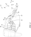
- FIG. 4 illustrates a perspective view of the implement compartment 120 in the operational position S1 of the spoiler 140 , in accordance with an exemplary embodiment of the present disclosure.
- the extending direction N of the flexible member 144 is substantially along the spoiler direction C .
- the spoiler 140 may be pivoted (as shown by the arrow F1 ) about the axis X-X' with respect to the implement compartment 120 allowing the extending direction N of the flexible member 144 to move relative to the implement compartment 120 .
- the spoiler 140 may be pivoted between the storage position S2 (shown in FIGS. 2-3 ) and the operational position S1 based on operational requirements. Further, the spoiler 140 is toollessly adjusted along the spoiler direction C relative to the implement compartment 120 in the form-fit manner to extend the lower front edge 132 . For example, the user may be able to toollessly adjust the spoiler 140 by pivoting the spoiler 140 about the axis X-X' relative to the implement compartment 120 based on the operational requirements. The spoiler 140 may be able to retain its position as the rigid holding member 142 is pivotally coupled to the at least one connecting member 134 in the form-fit manner. It should be understood that the spoiler 140 may be adjusted to any intermediate position between the operational position S1 and the storage position S2 (shown in FIGS. 2-3 ) in the form-fit manner.
- FIG. 5 illustrates a perspective view of the spoiler 140 , in accordance with an exemplary embodiment of the present disclosure.
- the spoiler 140 further includes at least one slot 148 .
- the at least one slot 148 extends from the distal edge 146 of the flexible member 144 at least partially towards the proximal edge 147 of the flexible member 144 .
- the spoiler 140 further includes at least one flexible locking member 150 coupled to and extending from the rigid holding member 142 adjacent to the at least one connecting member 134 (shown in FIGS. 3-4 ).
- the at least one flexible locking member 150 includes a pair of flexible locking members 150 .
- the spoiler 140 may include any number of the flexible locking members 150 .
- FIG. 6 illustrates a perspective view of the spoiler 140 and the at least one connecting member 134 in the storage position S2 of the spoiler 140 , in accordance with an exemplary embodiment of the present disclosure.
- the at least one flexible locking member 150 in the storage position S2 , is adapted to lockingly and releasably engage with the connecting surface 136 of the at least one connecting member 134 , such that the spoiler 140 is restricted from pivoting about the axis X-X' relative to the implement compartment 120 (shown in FIGS. 1-4 ) .
- each of the pair of flexible locking members 150 (only one visible) is adapted to lockingly and releasably engage with the connecting surface 136 of the corresponding connecting member 134 .
- the at least one flexible locking member 150 of the spoiler 140 engages with the connecting surface 136 of the at least one connecting member 134 , thereby restricting the pivoting movement of the spoiler 140 and locking the spoiler 140 in the storage position S2 .
- FIG. 7 illustrates a perspective view of the spoiler 140 and the at least one connecting member 134 in the operational position S2 of the spoiler 140 , in accordance with an exemplary embodiment of the present disclosure.
- the at least one flexible locking member 150 is disengaged from the connecting surface 136 of the at least one connecting member 134 .
- the spoiler 140 is pivoted about the axis X-X' relative to the implement compartment 120 (shown in FIGS. 1-4 ) from the storage position S2 (shown in FIGS.
- the at least one flexible locking member 150 of the spoiler 140 may flex and disengage from the connecting surface 136 of the at least one connecting member 134 , thereby releasing the spoiler 140 and allowing pivoting movement of the spoiler 140 .
- the spoiler 140 may be held at any intermediate position between the operational position S1 and the storage position S2 (shown in FIGS. 2 , 3 & 6 ).
- FIG. 8 illustrates a perspective view of the material collection equipment 100 , in accordance with another exemplary embodiment of the present disclosure. Some components of the material collection equipment 100 are not shown for the purpose of illustration.
- the material collection equipment 100 includes a spoiler 240 coupled to the implement compartment 120.
- the spoiler 240 may be similar to the spoiler 140 shown in FIGS. 1-7 , and the same or equivalent elements or elements having the same or equivalent functionality are indicated by the same or equivalent reference numbers in the following description.
- the spoiler 240 is removably coupled to the implement compartment 120 .
- material collection equipment 100 further includes at least one securing member 252 removably coupling the spoiler 240 to the implement compartment 120 .
- the at least one securing member 252 includes three securing members 252. However, it should be understood that the at least one securing member 252 may include any number of the securing member 252 .
- the spoiler 240 includes a rigid holding member 242 extending along the second axis B-B' and removably coupled to the implement compartment 120 .
- the spoiler 240 further includes a flexible member 244 extending from the rigid holding member 242 away from the implement compartment 120 .
- the flexible member 244 defines a distal edge 246 away from the rigid holding member 242 .
- the spoiler 240 further includes at least one slot 248 .
- the at least one slot 248 extends from the distal edge 246 of the flexible member 244 at least partially towards the rigid holding member 242 .
- the at least one slot 248 includes a plurality of slots 248 . Each of the plurality of slots 248 extends from the distal edge 246 at least partially towards the rigid holding member 242 .
- the spoiler 240 is removably coupled to the implement compartment 120 between a first position P1 and a second position P2 (shown in FIG. 10 ).
- a distance D1 exists between the distal edge 246 of the flexible member 244 and the running surface 126, 128 of each wheel 124, 125 along the spoiler direction C in the first position P1 of the spoiler 140 .
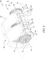
- FIG. 9 illustrates a partial exploded perspective view of the material collection equipment 100 , in accordance with an exemplary embodiment of the present disclosure.
- the implement compartment 120 includes at least one receiving portion 262 disposed adjacent to the lower front edge 132 .
- the at least one securing member 252 includes an elongated portion 261 .
- the at least one securing member 252 further includes a projection 264 extending transversely from the elongated portion 261 and configured to engage with walls (e.g., a groove within the walls) of the corresponding receiving portion 262 .
- the elongated portion 261 is adapted to be at least partially received through the corresponding receiving portion 262 .
- the at least one securing member 252 may be rotated after inserting the elongated portion 261 into the corresponding receiving portion 262 , thereby allowing the projection 264 to engage with the walls of the corresponding receiving portion 262 .
- the at least one securing member 252 may secure the spoiler 240 to the implement compartment 120 in the form-fir manner.
- the at least one securing member 252 may include any other suitable means for securing the spoiler 240 to the implement compartment 120 in the form-fit manner.
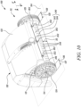
- FIG. 10 illustrates a perspective view of the material collection equipment 100 in the second position P2 of the spoiler 240 , in accordance with an exemplary embodiment of the present disclosure. Some components of the material collection equipment 100 are not shown for the purpose of illustration.
- a distance D2 exists between the distal edge 246 of the flexible member 244 and the running surface 126, 128 of each wheel 124, 125 along the spoiler direction C in the second position P2 of the spoiler 140 .
- the distance D1 (shown in FIG. 8 ) in the first position P1 (shown in FIG. 8 ) of the spoiler 140 is greater than the distance D2 in the second position P2 of the spoiler 140 .
- the at least one securing member 252 may allow the spoiler 240 to be removed from the first position P1 (shown in FIG. 8 ) and coupled to the implement compartment 120 again in the second position P2 .
- the at least one securing member 252 may allow the spoiler 240 to be toollessly adjusted along the spoiler direction C relative to the implement compartment 120 in the form-fit manner to extend the lower front edge 132 (shown in FIG. 9 ).
- the lower front edge 132 may be adjusted starting from a maximum distance from the running surface 126, 128 (shown in FIG. 8 ). It should be understood that the spoiler 240 may be adjusted relative to the implement compartment 120 at any intermediate position between the first position P1 (shown in FIG. 8 ) and the second position P2 .
- FIG. 11 illustrates a perspective view of a portion of the material collection equipment 100 , in accordance with another exemplary embodiment of the present disclosure. Some components of the material collection equipment 100 are not shown for the purpose of illustration.
- the material collection equipment 100 includes a spoiler 340 coupled to the implement compartment 120 .
- the spoiler 340 may be similar to the spoiler 140 (shown in FIGS. 1-7 ) and the spoiler 240 (shown in FIGS. 8-10 ), and the same or equivalent elements or elements having the same or equivalent functionality are indicated by the same or equivalent reference numbers in the following description.
- the spoiler 340 is removably coupled to the implement compartment 120.
- the spoiler 340 includes at least one engaging member 356 for securing the spoiler 340 to the implement compartment 120 .
- the at least one engaging member 356 includes a pair of engaging members 356 .
- the spoiler 340 includes an elastic member 343 extending along the second axis B-B' and removably coupled to the implement compartment 120 .
- the spoiler 340 further includes a flexible member 344 extending from the elastic member 343 away from the implement compartment 120 .
- an elasticity of the flexible member 344 is different from an elasticity of the elastic member 343 .
- the flexible member 344 defines a distal edge 346 away from the elastic member 343 .
- the spoiler 340 includes at least one slot 348 .
- the at least one slot 348 extends from the distal edge 346 of the flexible member 344 at least partially towards the elastic member 343.
- the at least one slot 348 includes a plurality of slots 348 . Each of the plurality of slots 348 extends from the distal edge 346 at least partially towards the elastic member 343 .
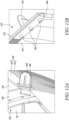
- FIG. 12A illustrates a perspective view of a portion of the implement compartment 120 and the spoiler 340 , in accordance with an exemplary embodiment of the present disclosure.
- the implement compartment 120 further includes at least one rib 354 disposed on the side wall 121 (i.e., the first side wall 121 shown in FIGS. 1-4 , 8-10 ) of the implement compartment 120 .
- the side wall 121 i.e., the first side wall 121 shown in FIGS. 1-4 , 8-10
- the second side wall 122 shown in FIGS. 1-2
- the spoiler 340 further includes the at least one engaging member 356 corresponding to the at least one rib 354 .
- the at least one engaging member 356 is fixedly coupled to the elastic member 343 .
- the at least one engaging member 356 removably engages with the at least one rib 354 , such that the spoiler 340 is removably coupled to the implement compartment 120 .
- the at least one rib 354 may include an opening (not shown) adapted to receive at least a portion of the at least one engaging member 356 for removably coupling the spoiler 340 to the implement compartment 120 .
- the at least one engaging member 356 may be manipulated for removing the spoiler 340 from the implement compartment 120 .
- the spoiler 340 further includes a holding member 358 adapted to allow the user to remove or attach the at least one engaging member 356 to the at least one rib 354 of the implement compartment 120 .
- FIG. 12B illustrates a perspective view of a portion of the spoiler 340 , in accordance with an exemplary embodiment of the present disclosure.
- the holding member 358 is secured to the at least one engaging member 356 via at least one protrusion 360 extending from the holding member 358 .
- the at least one protrusion 360 is at least partially received through the elastic member 343 and the at least one engaging member 356 .
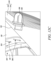
- FIG. 12C illustrates an exploded perspective view of a portion of the implement compartment 120 and the spoiler 340 , in accordance with an exemplary embodiment of the present disclosure.
- the at least one rib 354 may include a plurality of indents 366 spaced apart from each other. In an embodiment as shown in FIG. 12C , only two indents 366 are visible.
- the implement compartment 120 may include any number of the indents 166 .
- the plurality of indents 366 are disposed at predetermined heights. The plurality of indents 366 may allow the spoiler 340 to be correctly positioned relative to the implement compartment 120 at the predetermined heights.
- the present disclosure provides the material collection equipment 100 that includes the spoiler 140, 240, 340 coupled to the implement compartment 120 and disposed adjacent to the lower front edge 132 of the implement compartment 120 .
- the spoiler may allow the user of the material collection equipment 100 to easily manipulate a free space between the lower front edge 132 of the implement compartment 120 and the running surface 126, 128 , thereby mitigating dirt and dust disappearing out of the implement department 120 when working on surfaces such as paved surfaces, concrete, etc.
- the free space may be varied staring from a maximum free space.
- the spoiler 140, 240, 340 of the present disclosure may be toollessly adjusted along the spoiler direction C relative to the implement compartment 120 in the form-fit manner.
- the spoiler 140, 240, 340 may not require any additional tools for adjusting the spoiler 140, 240, 340 relative to the implement compartment 120 , thereby promoting user-friendliness and ease of using the spoiler 140, 240, 340 .
- the spoiler 140, 240, 340 may operate as a flexible curtain that prevents the material 102 (e.g., leaves, branches, etc.) from being thrown forward by the implement 106 and out of the range of the implement 106 . Therefore, the material 102 may be constrained by the spoiler 140, 240, 340 and eventually picked up by the implement 106 .
- the spoiler 140, 240, 340 of the present disclosure may improve a collection performance of the material collection equipment 100 even on the ground surfaces 104 such as paved surfaces, concrete, etc. as well as on low cut lawns. This may mitigate the need for multiple operational cycles with the material collection equipment 100 on the same surface to collect the material 102 .
- the spoiler 140, 240, 340 of the present disclosure is disposed at a front of the implement compartment 120 . Therefore, the spoiler 140, 240, 340 may not negatively impact a performance of the material collection equipment 100 on the regular working surfaces and in a parking position of the material collection equipment 100 . Moreover, the spoiler 140, 240, 340 of the present disclosure is light-weighted and flexible, thereby allowing the spoiler 140, 240, 340 to move over the material 102 to be collected without pushing the material 102 .
- the at least one slot 148, 248, 348 may divide the spoiler 140, 240, 340 into a plurality of flexible latches, thereby enhancing the flexibility of the spoiler 140, 240, 340 to slide over solid obstacles without getting damaged.
Landscapes
- Engineering & Computer Science (AREA)
- Architecture (AREA)
- Civil Engineering (AREA)
- Structural Engineering (AREA)
- Handcart (AREA)
Abstract
A material collection equipment (100) includes a handle (110) extending along a first axis (A-A') and connected to an implement compartment (120). The implement compartment (120) defines a lower front edge (132) along a second axis (B-B') away from the handle (110). The second axis (B-B') extends transversely relative to the first axis (A-A'). The material collection equipment (100) further includes a pair of wheels (124, 125) rotatably coupled to the implement compartment (120) through a respective axle (114, 115). Each wheel (124, 125) includes a running surface (126, 128). Each wheel (124, 125) defines a spoiler direction (C) from a respective axle (114, 115) towards a mid (127, 129) of the respective running surface (126, 128). The material collection equipment (100) further includes a spoiler (140, 240, 340) coupled to the implement compartment (120) to extend the lower front edge (132) along the spoiler direction (C). The spoiler (140, 240, 340) is disposed adjacent to the lower front edge (132). The spoiler (140, 240, 340) is toollessly adjusted along the spoiler direction (C) relative to the implement compartment (120) in a form-fit manner to extend the lower front edge (132).
Description
- The present disclosure relates to a material collection equipment, and more particularly, to a spoiler for the material collection equipment.
- Hand-held material collection equipment including, but not limited to, mobile garden tools, such as leaf collecting devices (e.g., lawn sweepers, leaf sweepers, etc.) and lawn movers have been well known in the art. Such tools typically include an implement portion, a storage compartment in communication with the implement portion, and a handle connected to the implement portion and/or the storage compartment. During operation, the implement portion may collect and transfer leaf or any other object from a ground surface on which the tool is working to the storage compartment.
- Generally, a lower front edge of the implement portion may exhibit a free space towards the ground surface. Some tools may be designed to run on grass and collect the leaves lying on the surface of the grass. Thus, the free space can be large in such cases since wheels of the tool run on the ground surface while the leaves are on top of the surface of the grass. If such tools are utilized on surfaces such as paved surfaces or concrete to sweep away the leaves, the large free space may result in a lot of dirt and dust disappearing out of the implement department.
- An example of such a tool is disclosed in
EP 3 765 675 B 1. The '675 reference describes a material collection equipment that includes a handle, a storage compartment, an implement compartment, an axle, and a pair of wheels. The material collection equipment further includes an implement adapted to collect material from a ground surface and transfer the material into the storage compartment. - In view of the above, it is an objective of the present invention to solve or at least reduce the drawbacks discussed above. The objective is at least partially achieved by a material collection equipment that may allow a user to easily manipulate a free space between a front lower edge of the material collection equipment and a ground surface.
- According to an aspect of the present invention, the material collection equipment includes a handle extending along a first axis. The material collection equipment further includes a connection element connecting the handle with an implement compartment. The implement compartment defines a lower front edge along a second axis away from the handle. The second axis extends transversely relative to the first axis. The material collection equipment further includes an implement disposed within the implement compartment and adapted to collect a material from a ground surface and to transfer the material into a storage compartment. The material collection equipment further includes a pair of wheels. Each wheel from the pair of wheels is rotatably coupled to the implement compartment through a respective axle. Each wheel includes a running surface. Each wheel defines a spoiler direction from the respective axle towards a mid of the respective running surface. The material collection equipment is characterized in that a spoiler is coupled to the implement compartment to extend the lower front edge of the implement compartment along the spoiler direction. The spoiler is disposed adjacent to the lower front edge of the implement compartment. The spoiler is toollessly adjusted along the spoiler direction relative to the implement compartment in a form-fit manner to extend the lower front edge.
- The material collection equipment of the present disclosure includes the spoiler coupled to the implement compartment and disposed adjacent to the front lower edge of the implement compartment. The spoiler may allow a user of the material collection equipment to extend the lower front edge of the implement compartment, thereby enabling easy manipulation of a free space between the front lower edge of the implement compartment and the ground surface. This may mitigate dirt and dust disappearing out of the implement department when working on surfaces such as paved surfaces, concrete, etc.
- Additionally, the spoiler may operate as a flexible curtain that prevents the material (e.g., leaves, branches, etc.) from being thrown forward by the implement out of the range of the implement. Therefore, the material may be constrained by the spoiler and eventually picked up by the implement. Thus, the spoiler of the present disclosure may improve a collection performance of the material collection equipment even on ground surfaces such as paved surfaces, concrete, etc. as well as on low cut lawns. This may mitigate the need for multiple operational cycles with the material collection equipment on the same surface to collect the material.
- The spoiler of the present disclosure may be toollessly adjusted along the spoiler direction relative to the implement compartment in the form-fit manner. Thus, the spoiler may not require any additional tools for adjusting the spoiler relative to the implement compartment, thereby promoting user-friendliness and ease of using the spoiler. Further, the lower front edge may be adjusted starting from a maximum distance from the running surface.
- The spoiler of the present disclosure is disposed at a front of the implement compartment. Therefore, the spoiler may not negatively impact a performance of the material collection equipment on the regular working surfaces and in a parking position of the material collection equipment. Further, the spoiler of the present disclosure is light-weighted and flexible, thereby allowing the spoiler to move over the material to be collected without pushing the material.
- According to an exemplary embodiment of the invention, the spoiler is pivotally coupled to the implement compartment. Thus, the user may be able to manipulate the spoiler based on operational requirements and a type of the ground surface to be worked upon.
- According to an exemplary embodiment of the invention, the spoiler includes a rigid holding member extending along the second axis and pivotally coupled to the implement compartment. The spoiler further includes a flexible member extending from the rigid holding member away from the implement compartment. The flexible member defines a proximal edge disposed adjacent to the rigid holding member and a distal edge spaced apart from the proximal edge away from the rigid holding member. The flexible member further defines an extending direction from the proximal edge of the flexible member towards the distal edge of the flexible member. The rigid holding member may allow the spoiler to be pivotally coupled to the implement compartment in a safe and reliable manner while the flexible member may allow the spoiler to move over the material to be collected without pushing or damaging it. Further, the rigid holding member may be pivotally coupled to the implement compartment in the form-fit manner.
- According to an exemplary embodiment of the invention, the rigid holding member may be made of a plastic material that may be light weight. Further, the flexible member may be made of a polymeric material, such as rubber.
- According to an exemplary embodiment of the invention, the spoiler is pivotable relative to the implement compartment between an operational position and a storage position. In the operational position, the extending direction of the flexible member is substantially along the spoiler direction, and in the storage position, the extending direction of the flexible member is substantially opposite to the spoiler direction.
- Thus, the spoiler may be pivoted based on the operational requirements and the type of the ground surface to be worked upon. For example, the spoiler may be pivoted to the storage position in case the spoiler is no longer required, e.g., when working on long grass surfaces. Further, in the operational position, the distal edge of the flexible member may be disposed closer to the ground surface, thereby reducing any free space between the front lower edge of the implement compartment and the ground surface. According to an exemplary embodiment of the invention, the spoiler may be held at any intermediate position between the operational position and the storage position. Further, the spoiler may be toollessly adjusted (or moved between the operational position and the storage position) along the spoiler direction relative to the implement compartment in the form-fit manner, thereby retaining the spoiler at any of the intermediate positions.
- According to an exemplary embodiment of the invention, the spoiler may be pivotable to any position between the operational position and the storage position, thereby allowing the user to easily manipulate the free space between the front lower edge of the implement compartment and the ground surface.
- According to an exemplary embodiment of the invention, the material collection equipment further includes at least one connecting member fixedly coupled to the implement compartment and defining a connecting surface facing the spoiler. The rigid holding member is pivotally coupled to the connecting surface of the at least one connecting member. The connecting member may allow the rigid holding member of the spoiler to be reliably secured to the implement compartment.
- According to an exemplary embodiment of the invention, the at least one connecting member may be fixedly coupled to the implement compartment through any suitable coupling mechanisms, including, but not limited to, fasteners, adhesives, snap-fit connections, tongue and groove joints, etc.
- According to an exemplary embodiment of the invention, the spoiler further includes at least one flexible locking member coupled to and extending from the rigid holding member adjacent to the at least one connecting member. In the storage position, the at least one flexible locking member is adapted to lockingly and releasably engage with the connecting surface of the at least one connecting member, such that the spoiler is restricted from pivoting relative to the implement compartment. In the operational position, the at least one flexible locking member is disengaged from the connecting surface of the at least one connecting member.
- Thus, the at least one flexible locking member may allow the spoiler to be retained in the storage position when the spoiler is not required during operation of the material collection equipment. Further, the at least one flexible locking member may include a flexible shape that may be released from the connecting surface upon application of a force as the spoiler is pivoted to the operational position from the storage position. The at least one flexible locking member may be flexible to be able to be released from the connecting surface when required but stable enough to hold the spoiler in the storage position.
- According to an exemplary embodiment of the invention, the at least one flexible locking member is in the form of a loop allowing the at least one flexible locking member to flex and get released from the connecting surface of the at least one connecting member upon movement of the spoiler from the storage position to the operational position. According to an exemplary embodiment of the invention, the at least one flexible locking member may be made of a polymeric material, such as plastic.
- According to an exemplary embodiment of the invention, the spoiler further includes at least one slot. The at least one slot extends from the distal edge of the flexible member at least partially towards the proximal edge of the flexible member. The at least one slot may divide the spoiler into a plurality of flexible latches, thereby enhancing the flexibility of the spoiler to slide over solid obstacles without getting damaged.
- According to an exemplary embodiment of the invention, the at least one slot includes a plurality of slots. Each slot from the plurality of slots extends from the distal edge at least partially towards the proximal edge. The plurality of slots may divide the spoiler into multiple flexible latches, thereby further enhancing the flexibility of the spoiler.
- According to an exemplary embodiment of the invention, some of the plurality of slots may have a varying length. Thus, the spoiler may have a variable stiffness at different locations.
- According to an exemplary embodiment of the invention, the spoiler is removably coupled to the implement compartment. Thus, the spoiler may be easily removed when not required and in storage position. Further, the spoiler may be retrofitted to existing material collection equipment. Additionally, the spoiler may be sold as an aftermarket accessory. Moreover, the spoiler may be replaced upon wear and tear since the spoiler is removably coupled to the implement compartment.
- According to an exemplary embodiment of the invention, the spoiler includes a rigid holding member extending along the second axis and removably coupled to the implement compartment. The spoiler further includes a flexible member extending from the rigid holding member away from the implement compartment. The flexible member defines a distal edge away from the rigid holding member. The rigid holding member may allow the spoiler to be pivotally coupled to the implement compartment in a safe and reliable manner while the flexible member may allow the spoiler to move over the material to be collected without pushing or damaging it.
- According to an exemplary embodiment of the invention, the spoiler is removably coupled to the implement compartment between a first position and a second position. A distance between the distal edge of the flexible member and the running surface of each wheel along the spoiler direction in the first position is greater than a distance between the distal edge and the running surface of each wheel along the spoiler direction in the second position. Thus, the distance between the distal edge of the flexible member and the running surface of each wheel along the spoiler direction may be varied based on the type of ground surface and application requirements.
- According to an exemplary embodiment of the invention, the spoiler may be toollessly removed from the first position and again coupled to the material collection equipment in the second position for varying the distance between the distal edge of the flexible member and the running surface of each wheel along the spoiler direction.
- According to an exemplary embodiment of the invention, the material collection equipment further includes at least one securing member removably coupling the spoiler to the implement compartment. According to an exemplary embodiment of the invention, the implement compartment includes at least one receiving portion disposed adjacent to the lower front edge. Further, the at least one securing member includes an elongated portion. The at least one securing member further includes a projection extending transversely from the elongated portion and adapted to engage with walls (e.g., a groove within the walls) of the corresponding receiving portion.
- According to an exemplary embodiment, the elongated portion is adapted to be at least partially received through the corresponding receiving portion. According to an exemplary embodiment, the at least one securing member may be rotated after inserting the elongated portion into the corresponding receiving portion, thereby allowing the projection to engage with the walls of the corresponding receiving portion. Thus, the at least one securing member may secure the spoiler to the implement compartment in the form-fir manner.
- According to an exemplary embodiment of the invention, the spoiler includes an elastic member extending along the second axis and removably coupled to the implement compartment. The spoiler further includes a flexible member extending from the elastic member away from the implement compartment. An elasticity of the flexible member is different from an elasticity of the elastic member. The flexible member defines a distal edge away from the elastic member. The elastic member may allow the spoiler to be removably coupled to the implement compartment in a safe and reliable manner. The elastic member may be coupled to the implement compartment at both its ends. The flexible member may allow the spoiler to move over the material to be collected without pushing or damaging it. According to an exemplary embodiment of the invention, the elastic member may be less elastic than the flexible member and may act as an expander.
- According to an exemplary embodiment of the invention, the material collection equipment further includes at least one rib disposed along a side wall of the implement compartment. The material collection equipment further includes at least one engaging member corresponding to the at least one rib. The at least one engaging member is fixedly coupled to the elastic member. The at least one engaging member removably engages with the at least one rib, such that the spoiler is removably coupled to the implement compartment.
- Thus, the at least one engaging member may allow the spoiler to be removably coupled to the implement compartment. Further, the at least one engaging member may allow the spoiler to be suitably positioned relative to the at least one rib of the implement compartment, thereby enabling varying positions for the spoiler. For example, the spoiler may be positioned away from the lower front edge of the implement compartment during storage of the material collection equipment.
- According to an exemplary embodiment of the invention, the at least one rib may include an opening adapted to receive at least a portion of the at least one engaging member for removably coupling the spoiler to the implement compartment. The opening may allow the at least one engaging member to be secured to the implement compartment in a reliable manner.
- According to an exemplary embodiment of the invention, the at least one rib may include a plurality of indents spaced apart from each other. The plurality of indents may allow the spoiler to be correctly positioned relative to the implement compartment.
- According to an exemplary embodiment of the invention, the at least one engaging member may be in the form of a hook or any other suitable holding means. The hook may allow the user to easily remove and attached the spoiler to the at least one rib of the implement compartment.
- According to an exemplary embodiment of the invention, the spoiler further includes a holding member for allowing the user to secure the at least one engaging member to the at least one rib. According to an exemplary embodiment of the invention, the holding member is secured to the at least one engaging member via at least one protrusion extending from the holding member. According to an exemplary embodiment of the invention, the at least one protrusion is at least partially received through the elastic member and the at least one engaging member, thereby allowing the holding member to be secured to the at least one engaging member. Further, the holding member may allow the user to apply a force on the at least one engaging member for securing the at least one engaging member to the at least one rib.
- According to an exemplary embodiment of the invention, the spoiler further includes at least one slot. The at least one slot extends from the distal edge of the flexible member at least partially towards the rigid holding member. The at least one slot may divide the spoiler into a plurality of flexible latches, thereby enhancing the flexibility of the spoiler to slide over solid obstacles without getting damaged.
- Before discussing the invention with the help of the drawings, the invention will be briefly discussed in general. A material collection equipment is disclosed that includes a spoiler. The spoiler may allow a free space between a front lower edge of an implement compartment and a ground surface to be easily manipulated based on the application requirements. Additionally, a cleaning performance of the material collection equipment may be improved on surfaces such as paved surfaces, concrete, etc. as wells as on low cut lawns. The spoiler may operate as a flexible curtain that prevents a material to be collected from being thrown forward by an implement and out of a range of the implement. The spoiler may be attached at a front portion of the material collection equipment, thereby preventing any negative impact to the performance of the material collection equipment. The spoiler may be flexible enough to slide over solid obstacles without getting damaged. The spoiler may also be stored on the material collection equipment.
- Other features and aspects of this invention will be apparent from the following description and the accompanying drawings.
- The invention will be described in more detail with reference to the enclosed drawings, wherein:
-
FIG. 1 illustrates a perspective view of a material collection equipment, in accordance with an exemplary embodiment of the present disclosure; -
FIG. 2 illustrates a perspective view of a material collection equipment in a storage position of a spoiler, in accordance with an exemplary embodiment of the present disclosure; -
FIG. 3 illustrates a perspective view of an implement compartment in the storage position of the spoiler, with some components not shown, in accordance with an exemplary embodiment of the present disclosure; -
FIG. 4 illustrates a perspective view of the implement compartment in an operational position of the spoiler, with some components not shown, in accordance with an exemplary embodiment of the present disclosure; -
FIG. 5 illustrates a perspective view of the spoiler, in accordance with an exemplary embodiment of the present disclosure; -
FIG. 6 illustrates a perspective view of the spoiler and at least one connecting member in the storage position of the spoiler, in accordance with an exemplary embodiment of the present disclosure; -
FIG. 7 illustrates a perspective view of the spoiler and the at least one connecting member in the operational position of the spoiler, in accordance with an exemplary embodiment of the present disclosure; -
FIG. 8 illustrates a perspective view of the material collection equipment, with some components not shown, in accordance with another exemplary embodiment of the present disclosure; -
FIG. 9 illustrates a partial exploded perspective view of the material collection equipment ofFIG. 8 , with some components not shown, in accordance with an exemplary embodiment of the present disclosure; -
FIG. 10 illustrates a perspective view of the material collection equipment ofFIG. 8 in a second position of the spoiler, with some components not shown, in accordance with an exemplary embodiment of the present disclosure; -
FIG. 11 illustrates a perspective view of a portion of the material collection equipment, with some components not shown, in accordance with another exemplary embodiment of the present disclosure; -
FIG. 12A illustrates a perspective view of a portion of the implement compartment and the spoiler of the material collection equipment ofFIG. 11 , in accordance with an exemplary embodiment of the present disclosure; -
FIG. 12B illustrates a perspective view of a portion of the spoiler of the material collection equipment ofFIG. 11 , in accordance with an exemplary embodiment of the present disclosure; -
FIG. 12C illustrates an exploded perspective view of a portion of the implement compartment and the spoiler of the material collection equipment ofFIG. 11 , in accordance with an exemplary embodiment of the present disclosure. - The present invention will be described more fully hereinafter with reference to the accompanying drawings, in which example embodiments of the invention incorporating one or more aspects of the present invention are shown. This invention may, however, be embodied in many different forms and should not be construed as limited to the embodiments set forth herein; rather, these embodiments are provided so that this disclosure will be thorough and complete, and will fully convey the scope of the invention to those skilled in the art. For example, one or more aspects of the present invention may be utilized in other embodiments and even other types of structures and/or methods. In the drawings, like numbers refer to like elements.
- Certain terminology is used herein for convenience only and is not to be taken as a limitation on the invention. For example, "upper", "lower", "front", "rear", "side", "longitudinal", "lateral", "transverse", "upwards", "downwards", "forward", "backward", "sideward", "left," "right," "horizontal," "vertical," "upward", "inner", "outer", "inward", "outward", "top", "bottom", "higher", "above", "below", "central", "middle", "intermediate", "between", "end", "adjacent", "proximate", "near", "distal", "remote", "radial", "circumferential", or the like, merely describe the configuration shown in the Figures. Indeed, the components may be oriented in any direction and the terminology, therefore, should be understood as encompassing such variations unless specified otherwise.
-
FIG. 1 illustrates a perspective view of amaterial collection equipment 100, in accordance with an exemplary embodiment of the present disclosure. Thematerial collection equipment 100 is adapted to collect a material 102 (e.g., leaves, branches, dirt, grass, foliage, etc.) present on aground surface 104 and to store thematerial 102 therein. - In some embodiments, the
material collection equipment 100 may be a walk-behind leaf collector adapted to collect leaves present on a lawn surface and store the leaves therein. In some other embodiments, thematerial collection equipment 100 may be a floor cleaner adapted to collect debris present on a floor surface and store the debris therein, and the like. In an embodiment as shown inFIG. 1 , thematerial collection equipment 100 is illustrated as a leaf collecting device. However, in other embodiments of the present invention, thematerial collection equipment 100 may be a lawn mower, or other types of gardening equipment known to persons skilled in the art. - The
material collection equipment 100 includes ahandle 110 extending along a first axis A-A'. According to an exemplary embodiment, thehandle 110 is adapted to provide a pushing force therethrough to thematerial collection equipment 100 in order to propel thematerial collection equipment 100 on theground surface 104 during a work operation. According to an exemplary embodiment, thehandle 110 may be any suitable handle known in the art, such as a fixed handle, a swivel handle, a pivot handle, a telescopic handle, and the like. According to an exemplary embodiment, thehandle 110 includes agripping portion 112 coupled thereto. The grippingportion 112 is adapted to hold thehandle 110 during the work operation. According to an exemplary embodiment, thehandle 110 further includes acoupling portion 116 coupled thereto. Thecoupling portion 116 is adapted to support and/or couple thehandle 110 with respect to thematerial collection equipment 100. - The
material collection equipment 100 further includes astorage compartment 118 coupled to thehandle 110 and adapted to store thematerial 102 therein. According to an exemplary embodiment, thecoupling portion 116 of thehandle 110 is coupled to thestorage compartment 118. Thestorage compartment 118 includes a substantially hollow configuration. In some embodiments, thestorage compartment 118 may include a cover portion (not shown) provided thereon. The cover portion may be adapted to provide an enclosure on thestorage compartment 118. - The
material collection equipment 100 further includes an implementcompartment 120. According to an exemplary embodiment, thestorage compartment 118 is disposed adjacent to the implementcompartment 120. Thematerial collection equipment 100 further includes aconnection element 108 connecting thehandle 110 with the implementcompartment 120. - The
material collection equipment 100 further includes an implement 106 (shown inFIG. 2 ) disposed within the implementcompartment 120. The implement 106 is adapted to collect the material 102 from theground surface 104 and to transfer thematerial 102 into thestorage compartment 118. Thestorage compartment 118 is adapted to receive thematerial 102 therein during the work operation. Additionally, thestorage compartment 118 is adapted to temporally store thematerial 102 therein, based on application requirements. - The
material collection equipment 100 further includes a pair ofwheels wheel wheels compartment 120 through arespective axle axles wheels compartment 120 on theground surface 104. - Each
wheel surface surface wheel ground surface 104 during the work operation or when the pair ofwheels compartment 120 on theground surface 104. InFIG. 1 , the runningsurface surface respective wheel wheel respective axle respective running surface - The implement
compartment 120 includes afirst side wall 121, asecond side wall 122 opposite to and spaced apart from thefirst side wall 121, and atop wall 123 extending between thefirst side wall 121 and thesecond side wall 122. The implementcompartment 120 defines a lower front edge 132 (shown inFIG. 3 ) along a second axis B-B' away from thehandle 110. The second axis B-B' extends transversely relative to the first axis A-A'. According to an exemplary embodiment, thetop wall 123 defines the lower front edge 132 (shown inFIG. 3 ) extending between thefirst side wall 121 and thesecond side wall 122 along the second axis B-B'. - According to an exemplary embodiment, the first axis A-A' and the second axis B-B' may be bidirectional while the spoiler direction C may be unidirectional.
- According to an exemplary embodiment, the implement 106 may be coupled to an implement axle (not shown) rotatably disposed within the implement compartment. According to an exemplary embodiment, the implement axle may be directly or indirectly (e.g., via a transmission mechanism such as one or more gears, a belt pulley mechanism, contacting elements, and the like) coupled to the
respective axle wheels wheels compartment 120. Thus, the implement 106 is adapted to collect the material 102 from theground surface 104 upon rotation and to transfer thematerial 102 to thestorage compartment 118. - The
material collection equipment 100 further includes aspoiler 140 coupled to the implementcompartment 120 to extend the lower front edge 132 (shown inFIG. 3 ) of the implementcompartment 120 along the spoiler direction C. Thespoiler 140 is disposed adjacent to the lower front edge 132 (shown inFIG. 3 ) of the implementcompartment 120. In the illustrated embodiment ofFIG. 1 , thespoiler 140 is shown in an operational position S1. According to an exemplary embodiment, thespoiler 140 is pivotable relative to the implementcompartment 120. -
FIG. 2 illustrates a perspective view of thematerial collection equipment 100 in a storage position S2 of thespoiler 140, in accordance with an exemplary embodiment of the present disclosure. According to an exemplary embodiment, thespoiler 140 is pivotable relative to the implementcompartment 120 between the operational position S1 (shown inFIG. 1 ) and the storage position S2 as shown by the arrow F1. According to an exemplary embodiment, thespoiler 140 may be pivoted based on operational requirements of thematerial collection equipment 100 and a type of the ground surface 104 (shown inFIG. 1 ) to be worked upon. -
FIG. 3 illustrates a perspective view of the implementcompartment 120 in the storage position S2 of thespoiler 140, in accordance with an exemplary embodiment of the present disclosure. Some components of the implementcompartment 120 are not shown for the purpose of illustration. - According to an exemplary embodiment, the
spoiler 140 includes arigid holding member 142 extending at least partially along the second axis B-B' and pivotally coupled to the implementcompartment 120. According to an exemplary embodiment, the material collection equipment 100 (shown inFIGS. 1-2 ) further includes at least one connectingmember 134 fixedly coupled to the implementcompartment 120 and defining a connectingsurface 136 facing thespoiler 140. According to an exemplary embodiment, therigid holding member 142 is pivotally coupled to the at least one connectingmember 134. Specifically, therigid holding member 142 is pivotally coupled to the connectingsurface 136 of the at least one connectingmember 134 in a form-fit manner. Accordingly, therigid holding member 142 is pivotable about an axis X-X'. - In an embodiment as shown in
FIG. 3 , the at least one connectingmember 134 includes a pair of connectingmembers 134. However, it should be understood that the material collection equipment 100 (shown inFIGS. 1-2 ) may include any number of the at least one connectingmembers 134. Each of the pair of connectingmembers 134 includes a corresponding connectingsurface 136 disposed in front of thespoiler 140. Further, therigid holding member 142 is pivotally coupled to the connecting surface of each of the pair of connectingmembers 134. - According to an exemplary embodiment, the
spoiler 140 further includes aflexible member 144 extending from therigid holding member 142 away from the implementcompartment 120. Theflexible member 144 defines aproximal edge 147 disposed adjacent to therigid holding member 142 and adistal edge 146 spaced apart from theproximal edge 147 away from therigid holding member 142. - According to an exemplary embodiment, the
flexible member 144 further defines an extending direction N from theproximal edge 147 of theflexible member 144 towards thedistal edge 146 of theflexible member 144. According to an exemplary embodiment, in the storage position S2, the extending direction N of theflexible member 144 is substantially opposite to the spoiler direction C. -
FIG. 4 illustrates a perspective view of the implementcompartment 120 in the operational position S1 of thespoiler 140, in accordance with an exemplary embodiment of the present disclosure. According to an exemplary embodiment, in the operational position S1, the extending direction N of theflexible member 144 is substantially along the spoiler direction C. According to an exemplary embodiment, thespoiler 140 may be pivoted (as shown by the arrow F1) about the axis X-X' with respect to the implementcompartment 120 allowing the extending direction N of theflexible member 144 to move relative to the implementcompartment 120. - Thus, the
spoiler 140 may be pivoted between the storage position S2 (shown inFIGS. 2-3 ) and the operational position S1 based on operational requirements. Further, thespoiler 140 is toollessly adjusted along the spoiler direction C relative to the implementcompartment 120 in the form-fit manner to extend the lowerfront edge 132. For example, the user may be able to toollessly adjust thespoiler 140 by pivoting thespoiler 140 about the axis X-X' relative to the implementcompartment 120 based on the operational requirements. Thespoiler 140 may be able to retain its position as therigid holding member 142 is pivotally coupled to the at least one connectingmember 134 in the form-fit manner. It should be understood that thespoiler 140 may be adjusted to any intermediate position between the operational position S1 and the storage position S2 (shown inFIGS. 2-3 ) in the form-fit manner. -
FIG. 5 illustrates a perspective view of thespoiler 140, in accordance with an exemplary embodiment of the present disclosure. According to an exemplary embodiment, thespoiler 140 further includes at least oneslot 148. According to an exemplary embodiment, the at least oneslot 148 extends from thedistal edge 146 of theflexible member 144 at least partially towards theproximal edge 147 of theflexible member 144. - According to an exemplary embodiment, the
spoiler 140 further includes at least oneflexible locking member 150 coupled to and extending from therigid holding member 142 adjacent to the at least one connecting member 134 (shown inFIGS. 3-4 ). In an embodiment as shown inFIG. 5 , the at least oneflexible locking member 150 includes a pair offlexible locking members 150. However, it should be understood that thespoiler 140 may include any number of theflexible locking members 150. -
FIG. 6 illustrates a perspective view of thespoiler 140 and the at least one connectingmember 134 in the storage position S2 of thespoiler 140, in accordance with an exemplary embodiment of the present disclosure. According to an exemplary embodiment, in the storage position S2, the at least oneflexible locking member 150 is adapted to lockingly and releasably engage with the connectingsurface 136 of the at least one connectingmember 134, such that thespoiler 140 is restricted from pivoting about the axis X-X' relative to the implement compartment 120 (shown inFIGS. 1-4 ). In an embodiment as shown inFIG. 6 , each of the pair of flexible locking members 150 (only one visible) is adapted to lockingly and releasably engage with the connectingsurface 136 of the corresponding connectingmember 134. - According to an exemplary embodiment, as the
spoiler 140 is pivoted relative to the implement compartment 120 (shown inFIGS. 1-4 ) about the axis X-X' from the operational position S1 (shown inFIGS. 1 &4 ) to the storage position S2, the at least oneflexible locking member 150 of thespoiler 140 engages with the connectingsurface 136 of the at least one connectingmember 134, thereby restricting the pivoting movement of thespoiler 140 and locking thespoiler 140 in the storage position S2. -
FIG. 7 illustrates a perspective view of thespoiler 140 and the at least one connectingmember 134 in the operational position S2 of thespoiler 140, in accordance with an exemplary embodiment of the present disclosure. According to an exemplary embodiment, in the operational position S1, the at least oneflexible locking member 150 is disengaged from the connectingsurface 136 of the at least one connectingmember 134. According to an exemplary embodiment, as thespoiler 140 is pivoted about the axis X-X' relative to the implement compartment 120 (shown inFIGS. 1-4 ) from the storage position S2 (shown inFIGS. 2 ,3 &6 ) to the operational position S1, the at least oneflexible locking member 150 of thespoiler 140 may flex and disengage from the connectingsurface 136 of the at least one connectingmember 134, thereby releasing thespoiler 140 and allowing pivoting movement of thespoiler 140. According to an exemplary embodiment, thespoiler 140 may be held at any intermediate position between the operational position S1 and the storage position S2 (shown inFIGS. 2 ,3 &6 ). -
FIG. 8 illustrates a perspective view of thematerial collection equipment 100, in accordance with another exemplary embodiment of the present disclosure. Some components of thematerial collection equipment 100 are not shown for the purpose of illustration. Thematerial collection equipment 100 includes aspoiler 240 coupled to the implementcompartment 120. Thespoiler 240 may be similar to thespoiler 140 shown inFIGS. 1-7 , and the same or equivalent elements or elements having the same or equivalent functionality are indicated by the same or equivalent reference numbers in the following description. - In an embodiment as shown in
FIG. 8 , thespoiler 240 is removably coupled to the implementcompartment 120. According to an exemplary embodiment,material collection equipment 100 further includes at least one securingmember 252 removably coupling thespoiler 240 to the implementcompartment 120. In an embodiment as shown inFIG. 8 , the at least one securingmember 252 includes three securingmembers 252. However, it should be understood that the at least one securingmember 252 may include any number of the securingmember 252. - According to an exemplary embodiment, the
spoiler 240 includes arigid holding member 242 extending along the second axis B-B' and removably coupled to the implementcompartment 120. According to an exemplary embodiment, thespoiler 240 further includes aflexible member 244 extending from therigid holding member 242 away from the implementcompartment 120. According to an exemplary embodiment, theflexible member 244 defines adistal edge 246 away from therigid holding member 242. - According to an exemplary embodiment, the
spoiler 240 further includes at least oneslot 248. According to an exemplary embodiment, the at least oneslot 248 extends from thedistal edge 246 of theflexible member 244 at least partially towards therigid holding member 242. In an embodiment as shown inFIG. 8 , the at least oneslot 248 includes a plurality ofslots 248. Each of the plurality ofslots 248 extends from thedistal edge 246 at least partially towards therigid holding member 242. - According to an exemplary embodiment, the
spoiler 240 is removably coupled to the implementcompartment 120 between a first position P1 and a second position P2 (shown inFIG. 10 ). A distance D1 exists between thedistal edge 246 of theflexible member 244 and the runningsurface wheel spoiler 140. -
FIG. 9 illustrates a partial exploded perspective view of thematerial collection equipment 100, in accordance with an exemplary embodiment of the present disclosure. In an embodiment as shown inFIG. 9 , the implementcompartment 120 includes at least one receivingportion 262 disposed adjacent to the lowerfront edge 132. According to an exemplary embodiment, the at least one securingmember 252 includes anelongated portion 261. The at least one securingmember 252 further includes aprojection 264 extending transversely from theelongated portion 261 and configured to engage with walls (e.g., a groove within the walls) of the corresponding receivingportion 262. - According to an exemplary embodiment, the
elongated portion 261 is adapted to be at least partially received through the corresponding receivingportion 262. According to an exemplary embodiment, the at least one securingmember 252 may be rotated after inserting theelongated portion 261 into the corresponding receivingportion 262, thereby allowing theprojection 264 to engage with the walls of the corresponding receivingportion 262. Thus, the at least one securingmember 252 may secure thespoiler 240 to the implementcompartment 120 in the form-fir manner. It should be understood that the at least one securingmember 252 may include any other suitable means for securing thespoiler 240 to the implementcompartment 120 in the form-fit manner. -
FIG. 10 illustrates a perspective view of thematerial collection equipment 100 in the second position P2 of thespoiler 240, in accordance with an exemplary embodiment of the present disclosure. Some components of thematerial collection equipment 100 are not shown for the purpose of illustration. According to an exemplary embodiment, a distance D2 exists between thedistal edge 246 of theflexible member 244 and the runningsurface wheel spoiler 140. According to an exemplary embodiment, the distance D1 (shown inFIG. 8 ) in the first position P1 (shown inFIG. 8 ) of thespoiler 140 is greater than the distance D2 in the second position P2 of thespoiler 140. - According to an exemplary embodiment, the at least one securing
member 252 may allow thespoiler 240 to be removed from the first position P1 (shown inFIG. 8 ) and coupled to the implementcompartment 120 again in the second position P2. Thus, the at least one securingmember 252 may allow thespoiler 240 to be toollessly adjusted along the spoiler direction C relative to the implementcompartment 120 in the form-fit manner to extend the lower front edge 132 (shown inFIG. 9 ). Further, the lowerfront edge 132 may be adjusted starting from a maximum distance from the runningsurface 126, 128 (shown inFIG. 8 ). It should be understood that thespoiler 240 may be adjusted relative to the implementcompartment 120 at any intermediate position between the first position P1 (shown inFIG. 8 ) and the second position P2. -
FIG. 11 illustrates a perspective view of a portion of thematerial collection equipment 100, in accordance with another exemplary embodiment of the present disclosure. Some components of thematerial collection equipment 100 are not shown for the purpose of illustration. Thematerial collection equipment 100 includes aspoiler 340 coupled to the implementcompartment 120. Thespoiler 340 may be similar to the spoiler 140 (shown inFIGS. 1-7 ) and the spoiler 240 (shown inFIGS. 8-10 ), and the same or equivalent elements or elements having the same or equivalent functionality are indicated by the same or equivalent reference numbers in the following description. - In an embodiment as shown in
FIG. 11 , thespoiler 340 is removably coupled to the implementcompartment 120. According to an exemplary embodiment, thespoiler 340 includes at least one engagingmember 356 for securing thespoiler 340 to the implementcompartment 120. In an embodiment as shown inFIG. 11 , the at least one engagingmember 356 includes a pair of engagingmembers 356. - According to an exemplary embodiment, the
spoiler 340 includes anelastic member 343 extending along the second axis B-B' and removably coupled to the implementcompartment 120. According to an exemplary embodiment, thespoiler 340 further includes aflexible member 344 extending from theelastic member 343 away from the implementcompartment 120. According to an exemplary embodiment, an elasticity of theflexible member 344 is different from an elasticity of theelastic member 343. According to an exemplary embodiment, theflexible member 344 defines adistal edge 346 away from theelastic member 343. - According to an exemplary embodiment, the
spoiler 340 includes at least oneslot 348. According to an exemplary embodiment, the at least oneslot 348 extends from thedistal edge 346 of theflexible member 344 at least partially towards theelastic member 343. In an embodiment as shown inFIG. 11 , the at least oneslot 348 includes a plurality ofslots 348. Each of the plurality ofslots 348 extends from thedistal edge 346 at least partially towards theelastic member 343. -
FIG. 12A illustrates a perspective view of a portion of the implementcompartment 120 and thespoiler 340, in accordance with an exemplary embodiment of the present disclosure. According to an exemplary embodiment, the implementcompartment 120 further includes at least onerib 354 disposed on the side wall 121 (i.e., thefirst side wall 121 shown inFIGS. 1-4 , 8-10 ) of the implementcompartment 120. In an embodiment as shown inFIG. 12A , only onerib 354 is visible. However, it should be understood that the second side wall 122 (shown inFIGS. 1-2 ) may also include the at least onerib 354. - According to an exemplary embodiment, the
spoiler 340 further includes the at least one engagingmember 356 corresponding to the at least onerib 354. According to an exemplary embodiment, the at least one engagingmember 356 is fixedly coupled to theelastic member 343. According to an exemplary embodiment, the at least one engagingmember 356 removably engages with the at least onerib 354, such that thespoiler 340 is removably coupled to the implementcompartment 120. According to an exemplary embodiment, the at least onerib 354 may include an opening (not shown) adapted to receive at least a portion of the at least one engagingmember 356 for removably coupling thespoiler 340 to the implementcompartment 120. - According to an exemplary embodiment, the at least one engaging
member 356 may be manipulated for removing thespoiler 340 from the implementcompartment 120. According to an exemplary embodiment, thespoiler 340 further includes a holdingmember 358 adapted to allow the user to remove or attach the at least one engagingmember 356 to the at least onerib 354 of the implementcompartment 120. -
FIG. 12B illustrates a perspective view of a portion of thespoiler 340, in accordance with an exemplary embodiment of the present disclosure. According to an exemplary embodiment, the holdingmember 358 is secured to the at least one engagingmember 356 via at least oneprotrusion 360 extending from the holdingmember 358. According to an exemplary embodiment, the at least oneprotrusion 360 is at least partially received through theelastic member 343 and the at least one engagingmember 356. -
FIG. 12C illustrates an exploded perspective view of a portion of the implementcompartment 120 and thespoiler 340, in accordance with an exemplary embodiment of the present disclosure. According to an exemplary embodiment, the at least onerib 354 may include a plurality ofindents 366 spaced apart from each other. In an embodiment as shown inFIG. 12C , only twoindents 366 are visible. However, the implementcompartment 120 may include any number of the indents 166. Specifically, the plurality ofindents 366 are disposed at predetermined heights. The plurality ofindents 366 may allow thespoiler 340 to be correctly positioned relative to the implementcompartment 120 at the predetermined heights. The plurality ofindents 366 may also be provided on the at least one rib disposed at the second side wall 122 (shown inFIGS. 1-2 ) of the implementcompartment 120, thereby allowing thespoiler 340 to be correctly positioned at both its ends. - Referring to
FIGS. 1 to 12C , the present disclosure provides thematerial collection equipment 100 that includes thespoiler compartment 120 and disposed adjacent to the lowerfront edge 132 of the implementcompartment 120. The spoiler may allow the user of thematerial collection equipment 100 to easily manipulate a free space between the lowerfront edge 132 of the implementcompartment 120 and the runningsurface department 120 when working on surfaces such as paved surfaces, concrete, etc. The free space may be varied staring from a maximum free space. - The
spoiler compartment 120 in the form-fit manner. Thus, thespoiler spoiler compartment 120, thereby promoting user-friendliness and ease of using thespoiler - Additionally, the
spoiler material 102 may be constrained by thespoiler spoiler material collection equipment 100 even on the ground surfaces 104 such as paved surfaces, concrete, etc. as well as on low cut lawns. This may mitigate the need for multiple operational cycles with thematerial collection equipment 100 on the same surface to collect thematerial 102. - Further, the
spoiler compartment 120. Therefore, thespoiler material collection equipment 100 on the regular working surfaces and in a parking position of thematerial collection equipment 100. Moreover, thespoiler spoiler material 102. The at least oneslot spoiler spoiler - In the drawings and specification, there have been disclosed preferred embodiments and examples of the invention and, although specific terms are employed, they are used in a generic and descriptive sense only and not for the purpose of limitation of the scope of the invention being set forth in the following claims.
-
- 100
- Material Collection Equipment
- 102
- Material
- 104
- Ground Surface
- 106
- Implement
- 108
- Connection Element
- 110
- Handle
- 112
- Gripping Portion
- 114
- Axle
- 115
- Axle
- 116
- Coupling Portion
- 118
- Storage Compartment
- 120
- Implement Compartment
- 121
- First Side Wall
- 122
- Second Side Wall
- 123
- Top Wall
- 124
- Wheel
- 125
- Wheel
- 126
- Running Surface
- 127
- Mid
- 128
- Running Surface
- 129
- Mid
- 132
- Front Lower Edge
- 134
- Connecting Member
- 136
- Connecting Surface
- 140
- Spoiler
- 142
- Rigid Holding Member
- 144
- Flexible Member
- 146
- Distal Edge
- 147
- Proximal Edge
- 148
- Slot
- 150
- Flexible Locking Member
- 240
- Spoiler
- 242
- Rigid Holding Member
- 244
- Flexible Member
- 246
- Distal Edge
- 248
- Slot
- 252
- Securing Member
- 261
- Elongated Portion
- 262
- Receiving Portion
- 264
- Projection
- 340
- Spoiler
- 343
- Elastic Member
- 344
- Flexible Member
- 346
- Distal Edge
- 348
- Slot
- 354
- Rib
- 356
- Engaging Member
- 358
- Holding Member
- 360
- Protrusion
- 366
- Indent
- A-A'
- Axis
- B-B'
- Second Axis
- C
- Spoiler Direction
- D1
- Distance
- D2
- Distance
- F1
- Arrow
- N
- Extending Direction
- P1
- First Position
- P2
- Second Position
- S1
- Operational Position
- S2
- Storage Position
- X-X'
- Axis
Claims (15)
- A material collection equipment (100), comprising:a handle (110) extending along a first axis (A-A');a connection element (108) connecting the handle (110) with an implement compartment (120), the implement compartment (120) defining a lower front edge (132) along a second axis (B-B') away from the handle (110), wherein the second axis (B-B') extends transversely relative to the first axis (A-A');an implement (106) disposed within the implement compartment (120) and adapted to collect a material (102) from a ground surface (104) and to transfer the material (102) into a storage compartment (118);a pair of wheels (124, 125), wherein each wheel (124, 125) from the pair of wheels (124, 125) is rotatably coupled to the implement compartment (120) through a respective axle (114, 115), wherein each wheel (124, 125) comprises a running surface (126, 128), and wherein each wheel (124, 125) defines a spoiler direction (C) from the respective axle (114, 115) towards a mid (127, 129) of the respective running surface (126, 128);characterized in that:a spoiler (140, 240, 340) coupled to the implement compartment (120) to extend the lower front edge (132) of the implement compartment (120) along the spoiler direction (C), wherein the spoiler (140, 240, 340) is disposed adjacent to the lower front edge (132) of the implement compartment (120), and wherein the spoiler (140, 240, 340) is toollessly adjusted along the spoiler direction (C) relative to the implement compartment (120) in a form-fit manner to extend the lower front edge (132).
- The material collection equipment (100) according to claim 1, wherein the spoiler (140) is pivotable relative to the implement compartment (120).
- The material collection equipment (100) according to claim 2, wherein the spoiler (140) comprises:a rigid holding member (142) extending along the second axis (B-B') and pivotally coupled to the implement compartment (120); anda flexible member (144) extending from the rigid holding member (142) away from the implement compartment (120), wherein the flexible member (144) defines a proximal edge (147) disposed adjacent to the rigid holding member and a distal edge (146) spaced apart from the proximal edge (147) away from the rigid holding member (142), and wherein the flexible member (144) further defines an extending direction (N) from the proximal edge (147) of the flexible member (144) towards the distal edge (146) of the flexible member (144).
- The material collection equipment (100) according to claim 3, wherein the spoiler (140) is pivotable relative to the implement compartment (120) between an operational position (S1) and a storage position (S2), wherein, in the operational position (S1), the extending direction (N) of the flexible member (144) is substantially along the spoiler direction (C), and wherein, in the storage position (S2), the extending direction (N) of the flexible member (144) is substantially opposite to the spoiler direction (C).
- The material collection equipment (100) according to claim 3 or claim 4, further comprising at least one connecting member (134) fixedly coupled to the implement compartment (120) and defining a connecting surface (136) facing the spoiler (140), wherein the rigid holding member (142) is pivotally coupled to the at least one connecting member (134).
- The material collection equipment (100) according to claim 5, wherein the spoiler (140) further comprises at least one flexible locking member (150) coupled to and extending from the rigid holding member (142) adjacent to the at least one connecting member (134), and wherein:in the storage position (S2), the at least one flexible locking member (150) is adapted to lockingly and releasably engage with the connecting surface (136) of the at least one connecting member (134), such that the spoiler (140) is restricted from pivoting relative to the implement compartment (120); andin the operational position (S1), the at least one flexible locking member (150) is disengaged from the connecting surface (136).
- The material collection equipment (100) according to anyone of claims 3-6, wherein the spoiler (140) further comprises at least one slot (148), and wherein the at least one slot (148) extends from the distal edge (146) of the flexible member (144) at least partially towards the proximal edge (147) of the flexible member (144).
- The material collection equipment (100) according to claim 1, wherein the spoiler (240, 340) is removably coupled to the implement compartment (120).
- The material collection equipment (100) according to claim 8, wherein the spoiler (240) comprises:a rigid holding member (242) extending along the second axis (B-B') and removably coupled to the implement compartment (120); anda flexible member (244) extending from the rigid holding member (242) away from the implement compartment (120), wherein the flexible member (244) defines a distal edge (246) away from the rigid holding member (242).
- The material collection equipment (100) according to claim 9, wherein the spoiler (240) is removably coupled to the implement compartment (120) between a first position (P1) and a second position (P2), and wherein a distance (D1) between the distal edge (246) of the flexible member (244) and the running surface (126, 128) of each wheel (124, 125) along the spoiler direction (C) in the first position (P1) of the spoiler (240) is greater than a distance (D2) between the distal edge (246) and the running surface (126, 128) of each wheel (124, 125) along the spoiler direction (C) in the second position (P2) of the spoiler (240).
- The material collection equipment (100) according to anyone of claims 9-10, wherein the spoiler (240) further comprises at least one slot (248), and wherein the at least one slot (248) extends from the distal edge (246) of the flexible member (244) at least partially towards the rigid holding member (242).
- The material collection equipment (100) according to claim 8, wherein the spoiler (340) comprises:an elastic member (343) extending along the second axis (B-B') and removably coupled to the implement compartment (120); anda flexible member (344) extending from the elastic member (343) away from the implement compartment (120), wherein an elasticity of the flexible member (344) is different from an elasticity of the elastic member (343), and wherein the flexible member (344) defines a distal edge (346) away from the elastic member (343).
- The material collection equipment (100) according to claim 12, wherein:the implement compartment (120) further comprises at least one rib (354) disposed along a side wall (121) of the implement compartment (120); andthe spoiler (340) further comprises at least one engaging member (356) corresponding to the at least one rib (354), wherein the at least one engaging member (356) is fixedly coupled to the elastic member (343), and wherein the at least one engaging member (356) removably engages with the at least one rib (354), such that the spoiler (340) is removably coupled to the implement compartment (120).
- The material collection equipment (100) according to claim 12 or claim 13, wherein the spoiler (340) further comprises at least one slot (348), and wherein the at least one slot (348) extends from the distal edge (346) of the flexible member (344) at least partially towards the elastic member (343).
- The material collection equipment (100) according to anyone of the preceding claims, wherein the storage compartment (118) is disposed adjacent to the implement compartment (120).
Priority Applications (2)
| Application Number | Priority Date | Filing Date | Title |
|---|---|---|---|
| EP23160465.3A EP4428304A1 (en) | 2023-03-07 | 2023-03-07 | Material collection equipment and spoiler |
| CN202410262168.3A CN118621726A (en) | 2023-03-07 | 2024-03-07 | Material collection equipment and spoilers |
Applications Claiming Priority (1)
| Application Number | Priority Date | Filing Date | Title |
|---|---|---|---|
| EP23160465.3A EP4428304A1 (en) | 2023-03-07 | 2023-03-07 | Material collection equipment and spoiler |
Publications (1)
| Publication Number | Publication Date |
|---|---|
| EP4428304A1 true EP4428304A1 (en) | 2024-09-11 |
Family
ID=85510868
Family Applications (1)
| Application Number | Title | Priority Date | Filing Date |
|---|---|---|---|
| EP23160465.3A Pending EP4428304A1 (en) | 2023-03-07 | 2023-03-07 | Material collection equipment and spoiler |
Country Status (2)
| Country | Link |
|---|---|
| EP (1) | EP4428304A1 (en) |
| CN (1) | CN118621726A (en) |
Citations (4)
| Publication number | Priority date | Publication date | Assignee | Title |
|---|---|---|---|---|
| US2552382A (en) * | 1948-10-14 | 1951-05-08 | Root Arthur John | Rotary brush for lawn sweepers |
| US2700783A (en) * | 1953-07-16 | 1955-02-01 | Parker Sweeper Company | Adjustable hood for sweepers |
| DE1899839U (en) * | 1964-04-15 | 1964-09-03 | Wolf Geraet G M B H | SWEEPER. |
| EP3765675A1 (en) | 2018-03-16 | 2021-01-20 | Husqvarna Ab | Material collection equipment |
-
2023
- 2023-03-07 EP EP23160465.3A patent/EP4428304A1/en active Pending
-
2024
- 2024-03-07 CN CN202410262168.3A patent/CN118621726A/en active Pending
Patent Citations (4)
| Publication number | Priority date | Publication date | Assignee | Title |
|---|---|---|---|---|
| US2552382A (en) * | 1948-10-14 | 1951-05-08 | Root Arthur John | Rotary brush for lawn sweepers |
| US2700783A (en) * | 1953-07-16 | 1955-02-01 | Parker Sweeper Company | Adjustable hood for sweepers |
| DE1899839U (en) * | 1964-04-15 | 1964-09-03 | Wolf Geraet G M B H | SWEEPER. |
| EP3765675A1 (en) | 2018-03-16 | 2021-01-20 | Husqvarna Ab | Material collection equipment |
Also Published As
| Publication number | Publication date |
|---|---|
| CN118621726A (en) | 2024-09-10 |
Similar Documents
| Publication | Publication Date | Title |
|---|---|---|
| US7603782B2 (en) | Universal, trimmer line, hook disk system | |
| US8136333B1 (en) | Lawnmower cutting deck and releasable blade | |
| CN110290735B (en) | Tools for Surface Cleaning Units | |
| US6502381B2 (en) | Pick-up rake | |
| AU646781B2 (en) | Lawn edger | |
| CA2142054C (en) | Tool | |
| EP3466237B1 (en) | Pivoting handle assembly | |
| US6032447A (en) | Gardening tool | |
| US9867332B2 (en) | Operationally tiltable counter rotating twin blade mowing deck | |
| US6904743B2 (en) | Leaf rake combo kit | |
| US5272858A (en) | Attachment for leaf blowers | |
| US8001753B2 (en) | Grass raking system | |
| JP7560494B2 (en) | Device for collecting garden waste | |
| US20070289283A1 (en) | Raking devices for pull-type and push-type applications and adapters and methods for retrofitting pull-type raking devices for pull- and push-type applications | |
| US20170188516A1 (en) | Lawn Debris Blower Bagging System | |
| US7908837B2 (en) | Grass collector mounting system | |
| CN118621726A (en) | Material collection equipment and spoilers | |
| US6250697B1 (en) | Device for trapping debris against a toolhead | |
| US20110088366A1 (en) | Rotary raking or sweeping implement | |
| US11723304B2 (en) | Yard rake and debris pickup device | |
| EP1385365B1 (en) | A rake | |
| US9642296B1 (en) | Leaf and debris collector having two staffs with debris scoops | |
| EP4424474A1 (en) | Gripper device | |
| RU2709699C1 (en) | Manual electric storage broom for cleaning snow, ice, water, earth, leaves and garbage | |
| US20020073681A1 (en) | Mechanical rake with sweep |
Legal Events
| Date | Code | Title | Description |
|---|---|---|---|
| PUAI | Public reference made under article 153(3) epc to a published international application that has entered the european phase |
Free format text: ORIGINAL CODE: 0009012 |
|
| STAA | Information on the status of an ep patent application or granted ep patent |
Free format text: STATUS: REQUEST FOR EXAMINATION WAS MADE |
|
| 17P | Request for examination filed |
Effective date: 20231215 |
|
| AK | Designated contracting states |
Kind code of ref document: A1 Designated state(s): AL AT BE BG CH CY CZ DE DK EE ES FI FR GB GR HR HU IE IS IT LI LT LU LV MC ME MK MT NL NO PL PT RO RS SE SI SK SM TR |