EP4428269A1 - Carbon dioxide electrolysis device and method - Google Patents
Carbon dioxide electrolysis device and method Download PDFInfo
- Publication number
- EP4428269A1 EP4428269A1 EP23743456.8A EP23743456A EP4428269A1 EP 4428269 A1 EP4428269 A1 EP 4428269A1 EP 23743456 A EP23743456 A EP 23743456A EP 4428269 A1 EP4428269 A1 EP 4428269A1
- Authority
- EP
- European Patent Office
- Prior art keywords
- carbon dioxide
- water vapor
- dioxide electrolysis
- electrolysis
- cathode
- Prior art date
- Legal status (The legal status is an assumption and is not a legal conclusion. Google has not performed a legal analysis and makes no representation as to the accuracy of the status listed.)
- Pending
Links
Images




Classifications
-
- C—CHEMISTRY; METALLURGY
- C25—ELECTROLYTIC OR ELECTROPHORETIC PROCESSES; APPARATUS THEREFOR
- C25B—ELECTROLYTIC OR ELECTROPHORETIC PROCESSES FOR THE PRODUCTION OF COMPOUNDS OR NON-METALS; APPARATUS THEREFOR
- C25B1/00—Electrolytic production of inorganic compounds or non-metals
- C25B1/01—Products
- C25B1/23—Carbon monoxide or syngas
-
- C—CHEMISTRY; METALLURGY
- C25—ELECTROLYTIC OR ELECTROPHORETIC PROCESSES; APPARATUS THEREFOR
- C25B—ELECTROLYTIC OR ELECTROPHORETIC PROCESSES FOR THE PRODUCTION OF COMPOUNDS OR NON-METALS; APPARATUS THEREFOR
- C25B1/00—Electrolytic production of inorganic compounds or non-metals
- C25B1/01—Products
- C25B1/02—Hydrogen or oxygen
-
- C—CHEMISTRY; METALLURGY
- C25—ELECTROLYTIC OR ELECTROPHORETIC PROCESSES; APPARATUS THEREFOR
- C25B—ELECTROLYTIC OR ELECTROPHORETIC PROCESSES FOR THE PRODUCTION OF COMPOUNDS OR NON-METALS; APPARATUS THEREFOR
- C25B15/00—Operating or servicing cells
- C25B15/08—Supplying or removing reactants or electrolytes; Regeneration of electrolytes
-
- C—CHEMISTRY; METALLURGY
- C25—ELECTROLYTIC OR ELECTROPHORETIC PROCESSES; APPARATUS THEREFOR
- C25B—ELECTROLYTIC OR ELECTROPHORETIC PROCESSES FOR THE PRODUCTION OF COMPOUNDS OR NON-METALS; APPARATUS THEREFOR
- C25B15/00—Operating or servicing cells
- C25B15/08—Supplying or removing reactants or electrolytes; Regeneration of electrolytes
- C25B15/085—Removing impurities
-
- C—CHEMISTRY; METALLURGY
- C25—ELECTROLYTIC OR ELECTROPHORETIC PROCESSES; APPARATUS THEREFOR
- C25B—ELECTROLYTIC OR ELECTROPHORETIC PROCESSES FOR THE PRODUCTION OF COMPOUNDS OR NON-METALS; APPARATUS THEREFOR
- C25B9/00—Cells or assemblies of cells; Constructional parts of cells; Assemblies of constructional parts, e.g. electrode-diaphragm assemblies; Process-related cell features
- C25B9/17—Cells comprising dimensionally-stable non-movable electrodes; Assemblies of constructional parts thereof
- C25B9/19—Cells comprising dimensionally-stable non-movable electrodes; Assemblies of constructional parts thereof with diaphragms
-
- C—CHEMISTRY; METALLURGY
- C25—ELECTROLYTIC OR ELECTROPHORETIC PROCESSES; APPARATUS THEREFOR
- C25B—ELECTROLYTIC OR ELECTROPHORETIC PROCESSES FOR THE PRODUCTION OF COMPOUNDS OR NON-METALS; APPARATUS THEREFOR
- C25B9/00—Cells or assemblies of cells; Constructional parts of cells; Assemblies of constructional parts, e.g. electrode-diaphragm assemblies; Process-related cell features
- C25B9/17—Cells comprising dimensionally-stable non-movable electrodes; Assemblies of constructional parts thereof
- C25B9/19—Cells comprising dimensionally-stable non-movable electrodes; Assemblies of constructional parts thereof with diaphragms
- C25B9/23—Cells comprising dimensionally-stable non-movable electrodes; Assemblies of constructional parts thereof with diaphragms comprising ion-exchange membranes in or on which electrode material is embedded
-
- C—CHEMISTRY; METALLURGY
- C25—ELECTROLYTIC OR ELECTROPHORETIC PROCESSES; APPARATUS THEREFOR
- C25B—ELECTROLYTIC OR ELECTROPHORETIC PROCESSES FOR THE PRODUCTION OF COMPOUNDS OR NON-METALS; APPARATUS THEREFOR
- C25B11/00—Electrodes; Manufacture thereof not otherwise provided for
- C25B11/02—Electrodes; Manufacture thereof not otherwise provided for characterised by shape or form
- C25B11/03—Electrodes; Manufacture thereof not otherwise provided for characterised by shape or form perforated or foraminous
- C25B11/031—Porous electrodes
- C25B11/032—Gas diffusion electrodes
-
- C—CHEMISTRY; METALLURGY
- C25—ELECTROLYTIC OR ELECTROPHORETIC PROCESSES; APPARATUS THEREFOR
- C25B—ELECTROLYTIC OR ELECTROPHORETIC PROCESSES FOR THE PRODUCTION OF COMPOUNDS OR NON-METALS; APPARATUS THEREFOR
- C25B11/00—Electrodes; Manufacture thereof not otherwise provided for
- C25B11/04—Electrodes; Manufacture thereof not otherwise provided for characterised by the material
- C25B11/051—Electrodes formed of electrocatalysts on a substrate or carrier
- C25B11/052—Electrodes comprising one or more electrocatalytic coatings on a substrate
-
- C—CHEMISTRY; METALLURGY
- C25—ELECTROLYTIC OR ELECTROPHORETIC PROCESSES; APPARATUS THEREFOR
- C25B—ELECTROLYTIC OR ELECTROPHORETIC PROCESSES FOR THE PRODUCTION OF COMPOUNDS OR NON-METALS; APPARATUS THEREFOR
- C25B11/00—Electrodes; Manufacture thereof not otherwise provided for
- C25B11/04—Electrodes; Manufacture thereof not otherwise provided for characterised by the material
- C25B11/051—Electrodes formed of electrocatalysts on a substrate or carrier
- C25B11/055—Electrodes formed of electrocatalysts on a substrate or carrier characterised by the substrate or carrier material
- C25B11/057—Electrodes formed of electrocatalysts on a substrate or carrier characterised by the substrate or carrier material consisting of a single element or compound
- C25B11/061—Metal or alloy
-
- C—CHEMISTRY; METALLURGY
- C25—ELECTROLYTIC OR ELECTROPHORETIC PROCESSES; APPARATUS THEREFOR
- C25B—ELECTROLYTIC OR ELECTROPHORETIC PROCESSES FOR THE PRODUCTION OF COMPOUNDS OR NON-METALS; APPARATUS THEREFOR
- C25B11/00—Electrodes; Manufacture thereof not otherwise provided for
- C25B11/04—Electrodes; Manufacture thereof not otherwise provided for characterised by the material
- C25B11/051—Electrodes formed of electrocatalysts on a substrate or carrier
- C25B11/073—Electrodes formed of electrocatalysts on a substrate or carrier characterised by the electrocatalyst material
- C25B11/075—Electrodes formed of electrocatalysts on a substrate or carrier characterised by the electrocatalyst material consisting of a single catalytic element or catalytic compound
- C25B11/081—Electrodes formed of electrocatalysts on a substrate or carrier characterised by the electrocatalyst material consisting of a single catalytic element or catalytic compound the element being a noble metal
-
- C—CHEMISTRY; METALLURGY
- C25—ELECTROLYTIC OR ELECTROPHORETIC PROCESSES; APPARATUS THEREFOR
- C25B—ELECTROLYTIC OR ELECTROPHORETIC PROCESSES FOR THE PRODUCTION OF COMPOUNDS OR NON-METALS; APPARATUS THEREFOR
- C25B11/00—Electrodes; Manufacture thereof not otherwise provided for
- C25B11/04—Electrodes; Manufacture thereof not otherwise provided for characterised by the material
- C25B11/051—Electrodes formed of electrocatalysts on a substrate or carrier
- C25B11/073—Electrodes formed of electrocatalysts on a substrate or carrier characterised by the electrocatalyst material
- C25B11/091—Electrodes formed of electrocatalysts on a substrate or carrier characterised by the electrocatalyst material consisting of at least one catalytic element and at least one catalytic compound; consisting of two or more catalytic elements or catalytic compounds
- C25B11/093—Electrodes formed of electrocatalysts on a substrate or carrier characterised by the electrocatalyst material consisting of at least one catalytic element and at least one catalytic compound; consisting of two or more catalytic elements or catalytic compounds at least one noble metal or noble metal oxide and at least one non-noble metal oxide
-
- Y—GENERAL TAGGING OF NEW TECHNOLOGICAL DEVELOPMENTS; GENERAL TAGGING OF CROSS-SECTIONAL TECHNOLOGIES SPANNING OVER SEVERAL SECTIONS OF THE IPC; TECHNICAL SUBJECTS COVERED BY FORMER USPC CROSS-REFERENCE ART COLLECTIONS [XRACs] AND DIGESTS
- Y02—TECHNOLOGIES OR APPLICATIONS FOR MITIGATION OR ADAPTATION AGAINST CLIMATE CHANGE
- Y02E—REDUCTION OF GREENHOUSE GAS [GHG] EMISSIONS, RELATED TO ENERGY GENERATION, TRANSMISSION OR DISTRIBUTION
- Y02E60/00—Enabling technologies; Technologies with a potential or indirect contribution to GHG emissions mitigation
- Y02E60/30—Hydrogen technology
- Y02E60/36—Hydrogen production from non-carbon containing sources, e.g. by water electrolysis
Definitions
- the present invention relates to a carbon dioxide electrolysis device and a carbon dioxide electrolysis method.
- Carbon dioxide is a greenhouse gas that causes global warming and is an object to be reduced.
- a method such as capture, chemical conversion, or electrochemical conversion is known as a method for reducing carbon dioxide.
- the electrochemical conversion method among these can precisely control components in order to produce another synthetic gas, and thus can obtain more economic gains than simply removing carbon dioxide.
- the process of electrochemically decomposing carbon dioxide is similar to water electrolysis technology, but since the activity of the electrochemical reaction is improved in a strong base condition, a certain concentration of an aqueous KOH solution is generally used as an electrolyte.
- an electric current is applied while supplying water to an anode, the water decomposes into hydrogen ions and electrons with oxygen gas generation.
- the electrons move to the cathode through an external conducting wire, and the hydrogen ions move to the cathode through an ion-selective membrane.
- the moved electrons react with the carbon dioxide and the water supplied to the cathode, thereby decomposing into carbon monoxide and hydroxide ions (OH-), and the resulting hydroxide ions are electrically neutral by reacting with hydrogen ions (H + ) of the anode to produce water.
- An electrochemical decomposition reaction of carbon dioxide is completed through the above process.
- the water supplied together with carbon dioxide reacts with the moved electrons, separately from the carbon monoxide production reaction, to be electrolyzed to generate hydrogen gas and simultaneously produce hydroxide ions.
- the reaction between the water and the electrons may be said to be a relationship of competition reaction with the carbon monoxide production reaction. Since the reactions above are electrochemical reactions, it is possible to easily control the amount of carbon monoxide produced and the hydrogen/carbon dioxide ratio by adjusting the voltage.
- K+ ions contained in the electrolyte are transferred to the cathode through the membrane, wherein the K+ ions react with the carbon dioxide of the cathode, and a salt such as potassium carbonate (K 2 CO 3 ) is precipitated.
- a salt such as potassium carbonate (K 2 CO 3 ) is precipitated.
- hydroxide ions mainly move, but cations such as K+ ions also partially move, and in this case, salt is produced as in the case of using the cation-conducting membrane.
- the salt produced and precipitated at the cathode above is accumulated inside the device as the carbon dioxide electrolysis process proceeds.
- the salt accumulated inside the device causes to block the inlet and the outlet for supplying and discharging carbon dioxide, thereby reducing the productivity and efficiency of the carbon dioxide electrolysis device, and making it impossible to continuously drive for a long period of time.
- the problem to be solved in the present invention is to dissolve and remove salts, by water, generated from an electrolyte during electrolysis of carbon dioxide.
- an aspect of the present invention provides a carbon dioxide electrolysis device and a carbon dioxide electrolysis method which can generate water by condensing water vapor when the water vapor supplied together with carbon dioxide is discharged together with the product of an electrolysis reaction during the electrolysis of carbon dioxide, and can dissolve and remove a salt, which is produced by side reactions of the electrolysis, by the water.
- the present invention provides a carbon dioxide electrolysis device and a carbon dioxide electrolysis method.
- water can be produced by using water vapor, as it is, supplied together with carbon dioxide, during carbon dioxide electrolysis, and the salt can be continuously removed by using the produced water without an additional salt removal device or salt removal operation.
- the carbon dioxide electrolysis device of the present invention does not require an additional salt removal device and an additional salt removal operation, there is no need for the salt removal device and space for removing the salt, and thus the volume of the carbon dioxide electrolysis device may be reduced.
- the salt can be continuously removed even without an additional salt removal device or salt removal operation, and thus the inlet and the outlet of the carbon dioxide electrolysis device are not blocked by the salt, so that the carbon dioxide electrolysis device can be smoothly and continuously driven without voltage changes, and the amount of production and electrolysis efficiency even with continuous driving are not reduced.
- the carbon dioxide electrolysis device of the present invention can easily condense water and dissolve salt through the special structure of the discharge line, and thus there is no need to add an additional condenser or an additional water spray device, and installation and maintenance are easily carried out, which is efficient in terms of structure facilities.
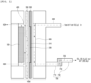
- FIG. 1 is a cross-sectional view for describing a carbon dioxide electrolysis device according to an embodiment of the present invention.
- the carbon dioxide electrolysis device of the present invention may include: a carbon dioxide electrolysis cell 1000 including an anode 100, a cathode 200, an electrolyte 400, and a membrane 300 disposed between the anode 100 and the cathode 200; a supply line 500 configured to supply gaseous carbon dioxide and water vapor to the cathode 200; and a discharge line 700 configured to discharge, into the outside of the cell, water vapor and a product produced by the electrolysis reaction of the carbon dioxide inside the carbon dioxide electrolysis cell 1000, wherein the discharge line 700 may include a condensation part 750 configured to condense the water vapor discharged through the discharge line 700.
- the carbon dioxide electrolysis cell 1000 is a device for converting carbon dioxide into carbon monoxide by injecting carbon dioxide and may include an anode 100, a cathode 200, an electrolyte 400, and a membrane 300. Electrolysis means that a DC voltage is applied to a decomposition reaction that does not occur spontaneously to cause an oxidation-reduction reaction, resulting in decomposition of materials.
- the anode 100 is an oxidation electrode, which generates oxygen by oxidizing water, and at the time, hydrogen ions are produced.
- the hydrogen ions produced in the anode 100 may be transferred to the cathode 200 through the electrolyte 400, and the cathode 200 is a reduction electrode, which may produce a product by reacting a reactant introduced into the cathode 200 with electrons and hydrogen ions transferred from the anode 100.
- the membrane 300 may be disposed between the anode 100 and the cathode 200.
- the membrane 300 may be composed of an inactive material that does not participate in itself in an electrochemical reaction, but may provide a path through which ions may move between the anode 100 and the cathode 200, and may serve to separate physical contact between the anode 100 and the cathode 200.
- each of the anode 100 and the cathode 200 of the carbon dioxide electrolysis cell 1000 of the present invention may include a catalyst layer.
- carbon dioxide supplied together with water vapor in the cathode region generates a reduction product by an electroreduction reaction on the surface of the cathode 200.
- the cathode 200 may include a gas diffusion layer 210 in order to uniformly supply the humidified carbon dioxide gas to the cathode region.
- the cathode 200 includes the hydrophobic gas diffusion layer 210, the supplied carbon dioxide may be smoothly diffused, distributed, and supplied to a catalyst layer 230 of the cathode.
- the hydrophobic gas diffusion layer 210 effectively prevents moisture condensation so that the supply of carbon dioxide is continuously uniform and at the same time, the electrolysis reaction may be smoothly performed.
- the catalyst layer 230 may have a surface such as a porous structure so that gas permeation characteristics are well exhibited on the surface.
- the anode 100 may include a catalyst having activity in the electrolysis of water, and the catalyst layer of the anode 100 may include at least one selected from the group consisting of Pt, Au, Pd, Ir, Ag, Rh, Ru, Ni, Al, Mo, Cr, Cu, Ti, W, an alloy thereof, or a mixed metal oxide, for example, Ta 2 0 5 , Ir0 2 , and the like, for oxygen generation reaction.
- the anode 100 in the carbon dioxide electrolysis device of the present invention may include nickel (Ni) coated with ruthenium oxide (RuO 2 ) and cerium oxide (CeO 2 ).
- the cathode 200 may include a catalyst which has a high voltage required for the hydrogen generation reaction and exhibits activity in the carbon dioxide reduction reaction.
- the catalyst layer 230 of the cathode 200 may include at least one selected from the group consisting of Sn, Sn alloy, Al, Au, Ag, C, Cd, Co, Cr, Cu, Cu alloy, Ga, Hg, In, Mo, Nb, Ni, NiCo 2 O 4 , Ni alloy, Ni-Fe alloy, Pb, Rh, Ti, V, W, Zn, and a mixture thereof, for the hydrogen generation reaction.
- the cathode 200 in the carbon dioxide electrolysis device of the present invention may include silver (Ag) .
- the membrane 300 may include a cation exchange membrane (CEM) or an anion exchange membrane (AEM).
- CEM cation exchange membrane
- AEM anion exchange membrane
- the electrolyte 400 may be selected from the group consisting of KHCO 3 , K 2 CO 3 , KOH, KCl, KClO 4 , K 2 SiO 3 , Na 2 SO 4 , NaNO 3 , NaCl, NaF, NaClO 4 , CaCl 2 , guanidinium cation, H + cation, alkali metal cation, ammonium cation, alkylammonium cation, halide ion, alkyl amine, borate, carbonate, guanidinium derivative, nitrite, nitrate, phosphate, polyphosphate, perchlorate, silicate, sulfate, tetraalkyl ammonium salt, or an aqueous solution containing a mixture thereof, and the electrolyte 400 of the carbon dioxide electrolysis device of the present invention may include KOH.
- the gas diffusion layer 210 may use a porous body using a carbon material such as carbon fiber fabric, carbon fiber felt, or carbon fiber paper, or a metal porous body formed of a thin metal plate having a net structure, such as expanded metal or metal mesh, and the gas diffusion layer in the carbon dioxide electrolysis device of the present invention may use carbon fiber fabric.
- a carbon material such as carbon fiber fabric, carbon fiber felt, or carbon fiber paper
- the carbon dioxide electrolysis device may include a supply line 500 which supplies gaseous carbon dioxide and water vapor to the cathode 200, a transfer line 600 which transfers the supplied carbon dioxide and water vapor to the cathode 200 so that the supplied carbon dioxide and water vapor move to the region of the cathode 200 to participate in the reaction with minimal resistance, and a discharge line 700 which discharges, into the outside of the cell, water vapor and a product produced by the reaction.
- a supply line 500 which supplies gaseous carbon dioxide and water vapor to the cathode 200
- a transfer line 600 which transfers the supplied carbon dioxide and water vapor to the cathode 200 so that the supplied carbon dioxide and water vapor move to the region of the cathode 200 to participate in the reaction with minimal resistance
- a discharge line 700 which discharges, into the outside of the cell, water vapor and a product produced by the reaction.
- the length, material, and shape of the supply line 500, the transfer line 600, and the discharge line 700 are not limited as long as they have a function to smoothly transfer carbon dioxide and water vapor.
- the shape of the transfer line 600 may include a parallel structure in which straight lines are disposed in parallel to each other or a serpentine structure having a repeated "S" shape.
- the supply line and the discharge line may be connected to the carbon dioxide electrolysis cell 1000, and the transfer line 600 may be disposed adjacent to the cathode 200 inside the carbon dioxide electrolysis cell 1000.
- the discharge line 700 may include a condensation part 750, and thus may be preferably positioned outside the carbon dioxide electrolysis cell 1000 and connected to the carbon dioxide electrolysis cell 1000.
- the carbon dioxide electrolysis device of the present invention may include the condensation part 750 in the discharge line 700.
- the condensation part 750 may serve to produce water by condensing the water vapor when the water vapor supplied through the supply line 500 is passed through a transfer line and discharged through the discharge line 700.
- the electrolyte 400-1 used during the electrolysis reaction in the carbon dioxide electrolysis device is present in a state of positive ions and negative ions, and when some of the positive ions move to the region of the cathode through the membrane 300-1, the positive ions react with carbon dioxide supplied to the region of the cathode to form and precipitate salts.
- the salt may not be removed and may be continuously accumulated in the carbon dioxide electrolysis cell, the supply line 500-1, and the discharge line 700-1, thereby blocking the supply line 500-1 and the discharge line 700-1.
- the carbon dioxide electrolysis device may not be continuously driven, and there may be a setback in experiments and research that require a long-term evaluation. Therefore, in order to remove such a salt, the carbon dioxide electrolysis device of the present invention may serve to dissolve the salt by the condensation part 750, which is positioned in the discharge line 700, converting the supplied water vapor into water, and thus the conventional limitations may be solved.
- the gaseous carbon dioxide may be supplied while including the water vapor. Since this may supply a larger amount than when the carbon dioxide is supplied alone, the efficiency of the carbon dioxide electrolysis device may be improved.
- the carbon dioxide and the water vapor may be bubbled through an additional humidifier and supplied while including the water vapor, or the carbon dioxide and the water vapor may be supplied while the carbon dioxide and the water vapor are in contact with each other and mixed through an additional device.
- the method of supplying the humidified carbon dioxide is not limited.
- the water vapor When the carbon dioxide is supplied in a humidified state, the water vapor may be converted into water through the condensation part 750 included in the discharge line 700, and thus there is an effect of reducing the volume of the carbon dioxide electrolysis device and simplifying the same.
- the water vapor supplied through the supply line 500 may have a temperature of 40 °C to 60 °C, specifically, at least 40 °C, at least 43 °C, at least 46 °C, at least 49 °C, and at most 60 °C, at most 57 °C, at most 54 °C, or at most 51 ° C.
- the carbon dioxide electrolysis device may be operated while maintaining a temperature of 40 °C to 60 °C, but the temperature of the device may be increased by heat or the temperature of feed in the carbon dioxide electrolysis device.
- the carbon dioxide electrolysis device should be operated in the above temperature range, and thus the electrolysis efficiency is maintained, and the production amount of the product is not reduced. Therefore, when the temperature of the supplied water vapor satisfies the above range, the carbon dioxide electrolysis device maintains the proper temperature, and thus there are effects of maintaining the production amount of the product and increasing the electrolysis efficiency.
- the condensation part 750 may be exposed to the outside of the carbon dioxide electrolysis cell 1000.
- the condensation part 750 may serve to condense the water vapor supplied through the supply line 500 and convert the condensed water vapor into water, and the condensation part 750 may be included in the discharge line 700 connected to the carbon dioxide electrolysis cell 1000.
- the condensation part 750 is exposed to the outside of the carbon dioxide electrolysis cell 1000 to be in contact with external air at room temperature, and may naturally condense the water vapor by the atmosphere at room temperature without an additional condenser or heat exchanger.
- the condensation part 750 is exposed to the outside of the carbon dioxide electrolysis cell 1000, so that no additional facilities for condensation are required, the volume of the device may be reduced, and no additional energy is required.
- the condensation part 750 may include a storage part 770 in which water formed by condensing water vapor discharged through the discharge line 700 is stored.
- the condensation part condenses the water vapor discharged through the discharge line 700 to form water, and the formed water dissolves and removes a salt which will be described later. Accordingly, when the formed water is stored in a certain space and the salt is discharged through the discharge line 700, a space in which the salt may be in contact with the water and dissolved may be required, and the carbon dioxide electrolysis device of the present invention includes the storage part 770 in the condensation part 750 included in the discharge line 700, thereby storing the condensed water and dissolving the salt in the storage part 770.
- the discharge line 700 may include a first line 710 through which the product and the water vapor discharged through the discharge line 700 are transferred from the carbon dioxide electrolysis cell 1000 to the condensation part 750, and a second line 730 through which the product is discharged from the condensation part 750 to the outside.
- the condensation part 750 may be included in the discharge line 700 connected to the carbon dioxide electrolysis cell 1000, and may serve to connect the first line 710 and the second line 730.
- the first line 710 may serve to transfer the water vapor and the product produced by the electrical reaction from the region of the cathode 200 to the condensation part 750, and since the water vapor may participate in some reactions, some of the supplied amount of water vapor may be discharged.
- the second line 730 may serve to discharge the product and the ion material produced by dissolving the salt from the condensation part 750 to the outside.
- the discharge line 700-1 in the conventional carbon dioxide electrolysis device generally has a simple straight tube shape, and has only the function of discharging the product of the electrolysis reaction.
- the discharge line 700 in the carbon dioxide electrolysis device of the present invention has a structure in which the condensation part 750 is disposed and connected between the first line 710 and the second line 730, it is not necessary to dispose the condensation part 750 in an additional space outside the discharge line 700, the product may be discharged to the outside without a plurality of separate discharge lines 700, and the salt produced as a by-product during the electrolysis reaction may be removed.
- the condensation part 750 may be connected so that a step between the first line 710 and the second line 730 is formed, and the second line 730 may be disposed higher than the first line 710 due to the step.
- the carbon dioxide electrolysis device of the present invention includes the discharge line 700 having a step structure of the first line 710 and the second line 730, and thus may include the condensation part 750 and the storage part 770 simultaneously without installing an additional space and device in the discharge line 700.
- the discharge line 700 of the carbon dioxide electrolysis device of the present invention may serve as a kind of filtering or threshold by connecting the first line 710 connected to the carbon dioxide electrolysis cell 1000 and the second line 730 for discharging the product to the outside via the condensation part 750 and forming a step such that the second line 730 is disposed higher than the first line 710.
- the product produced through the carbon dioxide electrolysis reaction may be carbon monoxide or hydrogen gas, and the product and the unreacted carbon dioxide gas may be discharged together.
- the salt produced as a by-product of electrolysis is produced by reacting the cations of the electrolyte 400 with the carbon dioxide to be ionic-bonded, and has a solid phase. Therefore, the gaseous product produced by the electrolysis reaction may be discharged to the outside through the discharge line, and the salt produced as a by-product during the electrolysis reaction may not be discharged to the outside due to the step and may be dissolved by being in contact with the water in the storage part 770.
- the height of the step may be a height capable of discharging the gaseous product and storing water produced by the condensation of the water vapor to be brought into contact with the salt, and there is no limitation.
- a carbon dioxide electrolysis method may include the steps of: (S1) supplying gaseous carbon dioxide and water vapor to a cathode 200 of a carbon dioxide electrolysis cell 1000 including an anode 100, the cathode 200, an electrolyte 400, and a membrane 300; (S2) electrolyzing the carbon dioxide supplied to the cathode 200 in step (S1) above; (S3) discharging, into the outside of the carbon dioxide electrolysis cell 1000, the product produced by the electrolysis in step (S2) above and the water vapor supplied in step (S1) above; and (S4) condensing the water vapor discharged in step (S3) above.
- the water formed by condensing the water vapor discharged in step (S4) above may dissolve the salt produced from the electrolyte 400 by electrolysis in step (S2) above.
- the carbon dioxide electrolysis method of the present invention may effectively remove the salt by condensing the water vapor and converting the condensed water vapor into water when discharging the water vapor supplied together with the carbon dioxide and the product produced by the electrolysis.
- the carbon dioxide electrolysis method of the present invention produces water by condensing the water vapor when the product and the water vapor are discharged, and removes salt by dissolving, thereby simplifying the process without the inconvenience of requiring a conventional complex and additional device, and enabling continuous long-term experiment and research.
- the carbon dioxide electrolysis method of the present invention may increase the amount of carbon dioxide supplied by supplying carbon dioxide and water vapor together, thereby increasing the amount of carbon monoxide produced, and since the carbon dioxide electrolysis method condenses the water vapor by using the supplied water vapor, there is no need to supply additional water for dissolving a salt when discharging the product and water vapor, thereby improving process efficiency.
- the salt may be produced by the reaction of the electrolyte 400 with the supplied carbon dioxide, and the salt may be KHCO 3 and K 2 CO 3 .
- KOH is used as an electrolyte in the carbon dioxide electrolysis method of the present invention
- potassium ions may react with carbon dioxide to produce potassium carbonate salts.
- a carbon dioxide electrolysis device for producing carbon monoxide by electroreducing carbon dioxide was manufactured.
- the carbon dioxide electrolysis device includes a condensation part 750 in a discharge line 700, and carbon dioxide electrolysis was performed by adjusting the operation conditions of the carbon dioxide electrolysis device as follows.
- a conversion rate (%) of carbon monoxide, CO Faraday efficiency (%), and a voltage during the electrolysis were measured in the same manner as in Example 1 above, except that a reaction current density was set as 300 mA/cm 2 .
- a conversion rate (%) of carbon monoxide, CO Faraday efficiency (%), and a voltage during the electrolysis were measured in the same manner as in Example 1 above, except that 1 M KHCO 3 (200 mL/min) was used as an anode electrolyte.
- a conversion rate (%) of carbon monoxide, CO Faraday efficiency (%), and a voltage during the electrolysis were measured in the same manner as in Example 1 above, except that the form of the transfer line changed from a parallel type to a serpentine type having a repeated "S" shape.
- a conversion rate (%) of carbon monoxide, CO Faraday efficiency (%), and a voltage during the electrolysis were measured in the same manner as in Example 4 above, except that a reaction current density was set as 300 mA/cm 2 .
- a conversion rate (%) of carbon monoxide, CO Faraday efficiency (%), and a voltage during the electrolysis were measured in the same manner as in Example 1 above, except that the cross-sectional area of the transfer line was changed to 0.75 mm 2 .
- a conversion rate (%) of carbon monoxide, CO Faraday efficiency (%), and a voltage during the electrolysis were measured in the same manner as in Example 6 above, except that a reaction current density was set as 300 mA/cm 2 .
- a conversion rate (%) of carbon monoxide, CO Faraday efficiency (%), and a voltage were measured in the same manner as in Example 1 above, except that the anode catalyst was changed from RuO 2 + CeO 2 on Ni mesh to IrO 2 -Ti mesh.
- a conversion rate (%) of carbon monoxide, CO Faraday efficiency (%), and a voltage during the electrolysis were measured in the same manner as in Example 8 above, except that a reaction current density was set as 300 mA/cm 2 .
- a conversion rate (%) of carbon monoxide, CO Faraday efficiency (%), and a voltage during the electrolysis were measured in the same manner as in Example 1 above, except that the condensation part was not included.
- a conversion rate (%) was calculated by a rate of the amount of the produced carbon monoxide (CO) to the amount of carbon dioxide (CO 2 ) gas introduced per hour.
- Equation 1 Q is a flow rate in the discharge line, F is the Faraday constant, p is a pressure, T is a measured temperature, and R is the ideal gas constant.
- the total current (i total ) is a value of the total current applied over time, and the current for the product (i product ) was a value calculated from a volume (V product ) of gas measured by the GC analysis.
- VSP potentiostat made by BioLogic.
- a booster of 80 A was installed to apply a current corresponding to a large area.
- the application of the current was maintained in stages at 100 mA/cm 2 , 200 mA/cm 2 , and 300 mA/cm 2 for a certain period of time, and then the voltage was recorded at the time point when 10 minutes elapsed.
- gas-chromatography (GC) analysis was also performed simultaneously.
- Comparative Example 1 in which the condensation part is not included in the discharge line, shows results of being inferior in terms of a conversion rate of carbon monoxide, CO Faraday efficiency, and a voltage to those of Examples 1 to 6 including the condensation part.
- Example 4 shows the conversion rate of carbon monoxide similar to that of Comparative Example 1, but shows better result values in terms of CO Faraday efficiency and a voltage.
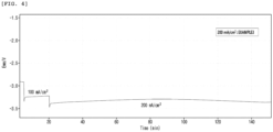
- FIGS. 3 to 6 show the voltage changes over time of Examples 1 to 6, and FIG. 7 shows the voltage change over time of Comparative Example 1.
- Comparative Example 1 it may be confirmed that in Comparative Example 1, the supply line and the discharge line are blocked by the salt produced during the electrolysis, causing abnormalities in supply and flow, and rapidly changing the voltage over time.
- Comparative Example 1 it may be confirmed that in Comparative Example 1, the supply line and the discharge line are blocked by the salt produced during the electrolysis, causing abnormalities in supply and flow, and rapidly changing the voltage over time.
- the conversion of carbon monoxide is smoothly performed while the voltage change is not large over time.
Landscapes
- Chemical & Material Sciences (AREA)
- Engineering & Computer Science (AREA)
- Chemical Kinetics & Catalysis (AREA)
- Electrochemistry (AREA)
- Materials Engineering (AREA)
- Metallurgy (AREA)
- Organic Chemistry (AREA)
- Inorganic Chemistry (AREA)
- Electrolytic Production Of Non-Metals, Compounds, Apparatuses Therefor (AREA)
Abstract
Description
- This application claims the benefit of
Korean Patent Application No. 10-2022-0007386, filed on January 18, 2022 - The present invention relates to a carbon dioxide electrolysis device and a carbon dioxide electrolysis method.
- Carbon dioxide is a greenhouse gas that causes global warming and is an object to be reduced. A method such as capture, chemical conversion, or electrochemical conversion is known as a method for reducing carbon dioxide. The electrochemical conversion method among these can precisely control components in order to produce another synthetic gas, and thus can obtain more economic gains than simply removing carbon dioxide.
- The process of electrochemically decomposing carbon dioxide is similar to water electrolysis technology, but since the activity of the electrochemical reaction is improved in a strong base condition, a certain concentration of an aqueous KOH solution is generally used as an electrolyte. When an electric current is applied while supplying water to an anode, the water decomposes into hydrogen ions and electrons with oxygen gas generation. The electrons move to the cathode through an external conducting wire, and the hydrogen ions move to the cathode through an ion-selective membrane. In this case, the moved electrons react with the carbon dioxide and the water supplied to the cathode, thereby decomposing into carbon monoxide and hydroxide ions (OH-), and the resulting hydroxide ions are electrically neutral by reacting with hydrogen ions (H+) of the anode to produce water. An electrochemical decomposition reaction of carbon dioxide is completed through the above process. In this case, the water supplied together with carbon dioxide reacts with the moved electrons, separately from the carbon monoxide production reaction, to be electrolyzed to generate hydrogen gas and simultaneously produce hydroxide ions. The reaction between the water and the electrons may be said to be a relationship of competition reaction with the carbon monoxide production reaction. Since the reactions above are electrochemical reactions, it is possible to easily control the amount of carbon monoxide produced and the hydrogen/carbon dioxide ratio by adjusting the voltage.
- Meanwhile, when a cation-conducting membrane is used as the ion-selective membrane, K+ ions contained in the electrolyte are transferred to the cathode through the membrane, wherein the K+ ions react with the carbon dioxide of the cathode, and a salt such as potassium carbonate (K2CO3) is precipitated. In addition, when an anion-conducting membrane is used as the ion-selective membrane, hydroxide ions mainly move, but cations such as K+ ions also partially move, and in this case, salt is produced as in the case of using the cation-conducting membrane.
- The salt produced and precipitated at the cathode above is accumulated inside the device as the carbon dioxide electrolysis process proceeds. Thus, the salt accumulated inside the device causes to block the inlet and the outlet for supplying and discharging carbon dioxide, thereby reducing the productivity and efficiency of the carbon dioxide electrolysis device, and making it impossible to continuously drive for a long period of time. In addition, there is a limitation that it is inefficient in terms of equipment facilities and operation because an additional device or operation is required to remove the salt.
- (Paten Document 001)
KR 10-1793711 B1 - The problem to be solved in the present invention is to dissolve and remove salts, by water, generated from an electrolyte during electrolysis of carbon dioxide.
- That is, an aspect of the present invention provides a carbon dioxide electrolysis device and a carbon dioxide electrolysis method which can generate water by condensing water vapor when the water vapor supplied together with carbon dioxide is discharged together with the product of an electrolysis reaction during the electrolysis of carbon dioxide, and can dissolve and remove a salt, which is produced by side reactions of the electrolysis, by the water.
- The present invention provides a carbon dioxide electrolysis device and a carbon dioxide electrolysis method.
- (1) According to an aspect of the present invention, there is provided a carbon dioxide electrolysis device including: a carbon dioxide electrolysis cell including an anode, a cathode, an electrolyte, and a membrane disposed between the anode and the cathode; a supply line configured to supply gaseous carbon dioxide and water vapor to the cathode; and a discharge line configured to discharge, into the outside of the carbon dioxide electrolysis cell, water vapor and a product produced by the electrolysis reaction of the carbon dioxide inside the carbon dioxide electrolysis cell, wherein the discharge line includes a condensation part configured to condense the water vapor discharged through the discharge line.
- (2) In (1) above of the present invention, there is provided the carbon dioxide electrolysis device, wherein the gaseous carbon dioxide is supplied while including the water vapor.
- (3) In (1) or (2) above of the present invention, there is provided the carbon dioxide electrolysis device, wherein the water vapor supplied through the supply line has a temperature of 40 °C to 60 °C.
- (4) In any one of (1) to (3) above of the present invention, there is provided the carbon dioxide electrolysis device, wherein the condensation part is exposed to the outside of the carbon dioxide electrolysis cell.
- (5) In any one of (1) to (4) above of the present invention, there is provided the carbon dioxide electrolysis device, wherein the condensation part includes a storage part configured to store water formed by condensing the water vapor discharged through the discharge line.
- (6) In any one of (1) to (5) above of the present invention, there is provided the carbon dioxide electrolysis device, wherein the discharge line includes a first line which transfers the product and the water vapor discharged through the discharge line from the carbon dioxide electrolysis cell to the condensation part, and a second line which discharges the product from the condensation part into the outside.
- (7) In (6) above of the present invention, there is provided the carbon dioxide electrolysis device, wherein the condensation part is connected so that a step is formed between the first line and the second line.
- (8) In (7) above of the present invention, there is provided the carbon dioxide electrolysis device, wherein the second line is disposed higher than the first line by the step.
- (9) According to another aspect of the present invention, there is provided a carbon dioxide electrolysis method including the steps of: (S1) supplying gaseous carbon dioxide and water vapor to a cathode of a carbon dioxide electrolysis cell including an anode, the cathode, an electrolyte, and a membrane; (S2) electrolyzing the carbon dioxide supplied to the cathode in step (S1) above; (S3) discharging, into the outside of the carbon dioxide electrolysis cell, the product produced by the electrolysis in step (S2) above and the water vapor supplied in step (S1) above; and (S4) condensing the water vapor discharged in step (S3) above.
- (10) In (9) above of the present invention, there is provided the carbon dioxide electrolysis method, wherein water formed by condensing the water vapor discharged in step (S4) above dissolves the salt produced from the electrolyte by the electrolysis in step (S2) above.
- (11) In (10) above of the present invention, there is provided the carbon dioxide electrolysis method, wherein the salt is produced by the reaction of the electrolyte with the supplied carbon dioxide.
- (12) In (10) or (11) above of the present invention, there is provided the carbon dioxide electrolysis method, wherein the salt is KHCO3 and K2CO3.
- According to the carbon dioxide electrolysis device and method of the present invention, water can be produced by using water vapor, as it is, supplied together with carbon dioxide, during carbon dioxide electrolysis, and the salt can be continuously removed by using the produced water without an additional salt removal device or salt removal operation.
- Also, because the carbon dioxide electrolysis device of the present invention does not require an additional salt removal device and an additional salt removal operation, there is no need for the salt removal device and space for removing the salt, and thus the volume of the carbon dioxide electrolysis device may be reduced.
- Also, according to the carbon dioxide electrolysis device and method of the present invention, the salt can be continuously removed even without an additional salt removal device or salt removal operation, and thus the inlet and the outlet of the carbon dioxide electrolysis device are not blocked by the salt, so that the carbon dioxide electrolysis device can be smoothly and continuously driven without voltage changes, and the amount of production and electrolysis efficiency even with continuous driving are not reduced.
- Also, the carbon dioxide electrolysis device of the present invention can easily condense water and dissolve salt through the special structure of the discharge line, and thus there is no need to add an additional condenser or an additional water spray device, and installation and maintenance are easily carried out, which is efficient in terms of structure facilities.
-
-
FIG. 1 is a cross-sectional view of a carbon dioxide electrolysis device according to an embodiment of the present invention. -
FIG. 2 is a cross-sectional view of a conventional carbon dioxide electrolysis device. -
FIG. 3 is a graph showing voltage changes over time of Examples 1 and 2. -
FIG. 4 is a graph showing a voltage change over time of Example 3. -
FIG. 5 is a graph showing voltage changes over time of Examples 4, 5, 6 and 7. -
FIG. 6 is a graph showing voltage changes over time of Examples 8 and 9. -
FIG. 7 is a graph showing a voltage change over time of Comparative Example 1. - Hereinafter, the present invention will be described in more detail to allow for a clearer understanding of the present invention. In this case, it will be understood that words or terms used in the specification and claims shall not be interpreted as the meaning defined in commonly used dictionaries, and it will be further understood that the words or terms should be interpreted as having a meaning that is consistent with their meaning in the context of the relevant art and the technical idea of the invention, based on the principle that an inventor may properly define the meaning of the words or terms to best explain the invention.
-
FIG. 1 is a cross-sectional view for describing a carbon dioxide electrolysis device according to an embodiment of the present invention. - Referring to
FIG. 1 , the carbon dioxide electrolysis device of the present invention may include: a carbondioxide electrolysis cell 1000 including ananode 100, acathode 200, anelectrolyte 400, and amembrane 300 disposed between theanode 100 and thecathode 200; asupply line 500 configured to supply gaseous carbon dioxide and water vapor to thecathode 200; and adischarge line 700 configured to discharge, into the outside of the cell, water vapor and a product produced by the electrolysis reaction of the carbon dioxide inside the carbondioxide electrolysis cell 1000, wherein thedischarge line 700 may include acondensation part 750 configured to condense the water vapor discharged through thedischarge line 700. - According to an embodiment of the present invention, the carbon
dioxide electrolysis cell 1000 is a device for converting carbon dioxide into carbon monoxide by injecting carbon dioxide and may include ananode 100, acathode 200, anelectrolyte 400, and amembrane 300. Electrolysis means that a DC voltage is applied to a decomposition reaction that does not occur spontaneously to cause an oxidation-reduction reaction, resulting in decomposition of materials. Theanode 100 is an oxidation electrode, which generates oxygen by oxidizing water, and at the time, hydrogen ions are produced. The hydrogen ions produced in theanode 100 may be transferred to thecathode 200 through theelectrolyte 400, and thecathode 200 is a reduction electrode, which may produce a product by reacting a reactant introduced into thecathode 200 with electrons and hydrogen ions transferred from theanode 100. In addition, themembrane 300 may be disposed between theanode 100 and thecathode 200. Themembrane 300 may be composed of an inactive material that does not participate in itself in an electrochemical reaction, but may provide a path through which ions may move between theanode 100 and thecathode 200, and may serve to separate physical contact between theanode 100 and thecathode 200. - In addition, each of the
anode 100 and thecathode 200 of the carbondioxide electrolysis cell 1000 of the present invention may include a catalyst layer. In addition, carbon dioxide supplied together with water vapor in the cathode region generates a reduction product by an electroreduction reaction on the surface of thecathode 200. Accordingly, thecathode 200 may include agas diffusion layer 210 in order to uniformly supply the humidified carbon dioxide gas to the cathode region. When thecathode 200 includes the hydrophobicgas diffusion layer 210, the supplied carbon dioxide may be smoothly diffused, distributed, and supplied to acatalyst layer 230 of the cathode. In addition, the hydrophobicgas diffusion layer 210 effectively prevents moisture condensation so that the supply of carbon dioxide is continuously uniform and at the same time, the electrolysis reaction may be smoothly performed. In addition, thecatalyst layer 230 may have a surface such as a porous structure so that gas permeation characteristics are well exhibited on the surface. - According to an embodiment of the present invention, the
anode 100 may include a catalyst having activity in the electrolysis of water, and the catalyst layer of theanode 100 may include at least one selected from the group consisting of Pt, Au, Pd, Ir, Ag, Rh, Ru, Ni, Al, Mo, Cr, Cu, Ti, W, an alloy thereof, or a mixed metal oxide, for example,Ta 205, Ir02, and the like, for oxygen generation reaction. Specifically, theanode 100 in the carbon dioxide electrolysis device of the present invention may include nickel (Ni) coated with ruthenium oxide (RuO2) and cerium oxide (CeO2). - In addition, since the carbon dioxide reduction reaction occurring in the
cathode 200 competes with the hydrogen generation reaction, thecathode 200 may include a catalyst which has a high voltage required for the hydrogen generation reaction and exhibits activity in the carbon dioxide reduction reaction. Thecatalyst layer 230 of thecathode 200 may include at least one selected from the group consisting of Sn, Sn alloy, Al, Au, Ag, C, Cd, Co, Cr, Cu, Cu alloy, Ga, Hg, In, Mo, Nb, Ni, NiCo2O4, Ni alloy, Ni-Fe alloy, Pb, Rh, Ti, V, W, Zn, and a mixture thereof, for the hydrogen generation reaction. Specifically, thecathode 200 in the carbon dioxide electrolysis device of the present invention may include silver (Ag) . - In addition, the
membrane 300 may include a cation exchange membrane (CEM) or an anion exchange membrane (AEM). - In addition, the
electrolyte 400 may be selected from the group consisting of KHCO3, K2CO3, KOH, KCl, KClO4, K2SiO3, Na2SO4, NaNO3, NaCl, NaF, NaClO4, CaCl2, guanidinium cation, H+ cation, alkali metal cation, ammonium cation, alkylammonium cation, halide ion, alkyl amine, borate, carbonate, guanidinium derivative, nitrite, nitrate, phosphate, polyphosphate, perchlorate, silicate, sulfate, tetraalkyl ammonium salt, or an aqueous solution containing a mixture thereof, and theelectrolyte 400 of the carbon dioxide electrolysis device of the present invention may include KOH. - In addition, the
gas diffusion layer 210 may use a porous body using a carbon material such as carbon fiber fabric, carbon fiber felt, or carbon fiber paper, or a metal porous body formed of a thin metal plate having a net structure, such as expanded metal or metal mesh, and the gas diffusion layer in the carbon dioxide electrolysis device of the present invention may use carbon fiber fabric. - According to an embodiment of the present invention, the carbon dioxide electrolysis device according to the present invention may include a
supply line 500 which supplies gaseous carbon dioxide and water vapor to thecathode 200, atransfer line 600 which transfers the supplied carbon dioxide and water vapor to thecathode 200 so that the supplied carbon dioxide and water vapor move to the region of thecathode 200 to participate in the reaction with minimal resistance, and adischarge line 700 which discharges, into the outside of the cell, water vapor and a product produced by the reaction. - The length, material, and shape of the
supply line 500, thetransfer line 600, and thedischarge line 700 are not limited as long as they have a function to smoothly transfer carbon dioxide and water vapor. The shape of thetransfer line 600 may include a parallel structure in which straight lines are disposed in parallel to each other or a serpentine structure having a repeated "S" shape. The supply line and the discharge line may be connected to the carbondioxide electrolysis cell 1000, and thetransfer line 600 may be disposed adjacent to thecathode 200 inside the carbondioxide electrolysis cell 1000. However, as described below, thedischarge line 700 may include acondensation part 750, and thus may be preferably positioned outside the carbondioxide electrolysis cell 1000 and connected to the carbondioxide electrolysis cell 1000. - According to an embodiment of the present invention, the carbon dioxide electrolysis device of the present invention may include the
condensation part 750 in thedischarge line 700. Thecondensation part 750 may serve to produce water by condensing the water vapor when the water vapor supplied through thesupply line 500 is passed through a transfer line and discharged through thedischarge line 700. - Meanwhile, the electrolyte 400-1 used during the electrolysis reaction in the carbon dioxide electrolysis device is present in a state of positive ions and negative ions, and when some of the positive ions move to the region of the cathode through the membrane 300-1, the positive ions react with carbon dioxide supplied to the region of the cathode to form and precipitate salts. In the case of the conventional carbon dioxide electrolysis device, the salt may not be removed and may be continuously accumulated in the carbon dioxide electrolysis cell, the supply line 500-1, and the discharge line 700-1, thereby blocking the supply line 500-1 and the discharge line 700-1. In this case, the carbon dioxide electrolysis device may not be continuously driven, and there may be a setback in experiments and research that require a long-term evaluation. Therefore, in order to remove such a salt, the carbon dioxide electrolysis device of the present invention may serve to dissolve the salt by the
condensation part 750, which is positioned in thedischarge line 700, converting the supplied water vapor into water, and thus the conventional limitations may be solved. - According to an embodiment of the present invention, the gaseous carbon dioxide may be supplied while including the water vapor. Since this may supply a larger amount than when the carbon dioxide is supplied alone, the efficiency of the carbon dioxide electrolysis device may be improved. Specifically, the carbon dioxide and the water vapor may be bubbled through an additional humidifier and supplied while including the water vapor, or the carbon dioxide and the water vapor may be supplied while the carbon dioxide and the water vapor are in contact with each other and mixed through an additional device. In this case, as long as the carbon dioxide can be supplied to the
cathode 200 through thesupply line 500 in a humidified state, the method of supplying the humidified carbon dioxide is not limited. - When the carbon dioxide is supplied in a humidified state, the water vapor may be converted into water through the
condensation part 750 included in thedischarge line 700, and thus there is an effect of reducing the volume of the carbon dioxide electrolysis device and simplifying the same. - According to an embodiment of the present invention, the water vapor supplied through the
supply line 500 may have a temperature of 40 °C to 60 °C, specifically, at least 40 °C, at least 43 °C, at least 46 °C, at least 49 °C, and at most 60 °C, at most 57 °C, at most 54 °C, or at most 51 ° C. The carbon dioxide electrolysis device may be operated while maintaining a temperature of 40 °C to 60 °C, but the temperature of the device may be increased by heat or the temperature of feed in the carbon dioxide electrolysis device. The carbon dioxide electrolysis device should be operated in the above temperature range, and thus the electrolysis efficiency is maintained, and the production amount of the product is not reduced. Therefore, when the temperature of the supplied water vapor satisfies the above range, the carbon dioxide electrolysis device maintains the proper temperature, and thus there are effects of maintaining the production amount of the product and increasing the electrolysis efficiency. - According to an embodiment of the present invention, the
condensation part 750 may be exposed to the outside of the carbondioxide electrolysis cell 1000. As described above, thecondensation part 750 may serve to condense the water vapor supplied through thesupply line 500 and convert the condensed water vapor into water, and thecondensation part 750 may be included in thedischarge line 700 connected to the carbondioxide electrolysis cell 1000. In addition, thecondensation part 750 is exposed to the outside of the carbondioxide electrolysis cell 1000 to be in contact with external air at room temperature, and may naturally condense the water vapor by the atmosphere at room temperature without an additional condenser or heat exchanger. In the carbon dioxide electrolysis device of the present invention, thecondensation part 750 is exposed to the outside of the carbondioxide electrolysis cell 1000, so that no additional facilities for condensation are required, the volume of the device may be reduced, and no additional energy is required. - According to an embodiment of the present invention, the
condensation part 750 may include astorage part 770 in which water formed by condensing water vapor discharged through thedischarge line 700 is stored. The condensation part condenses the water vapor discharged through thedischarge line 700 to form water, and the formed water dissolves and removes a salt which will be described later. Accordingly, when the formed water is stored in a certain space and the salt is discharged through thedischarge line 700, a space in which the salt may be in contact with the water and dissolved may be required, and the carbon dioxide electrolysis device of the present invention includes thestorage part 770 in thecondensation part 750 included in thedischarge line 700, thereby storing the condensed water and dissolving the salt in thestorage part 770. - According to an embodiment of the present invention, the
discharge line 700 may include afirst line 710 through which the product and the water vapor discharged through thedischarge line 700 are transferred from the carbondioxide electrolysis cell 1000 to thecondensation part 750, and asecond line 730 through which the product is discharged from thecondensation part 750 to the outside. Thecondensation part 750 may be included in thedischarge line 700 connected to the carbondioxide electrolysis cell 1000, and may serve to connect thefirst line 710 and thesecond line 730. Thefirst line 710 may serve to transfer the water vapor and the product produced by the electrical reaction from the region of thecathode 200 to thecondensation part 750, and since the water vapor may participate in some reactions, some of the supplied amount of water vapor may be discharged. In addition, thesecond line 730 may serve to discharge the product and the ion material produced by dissolving the salt from thecondensation part 750 to the outside. - Meanwhile, the discharge line 700-1 in the conventional carbon dioxide electrolysis device generally has a simple straight tube shape, and has only the function of discharging the product of the electrolysis reaction. On the other hand, since the
discharge line 700 in the carbon dioxide electrolysis device of the present invention has a structure in which thecondensation part 750 is disposed and connected between thefirst line 710 and thesecond line 730, it is not necessary to dispose thecondensation part 750 in an additional space outside thedischarge line 700, the product may be discharged to the outside without a plurality ofseparate discharge lines 700, and the salt produced as a by-product during the electrolysis reaction may be removed. - According to an embodiment of the present invention, the
condensation part 750 may be connected so that a step between thefirst line 710 and thesecond line 730 is formed, and thesecond line 730 may be disposed higher than thefirst line 710 due to the step. The carbon dioxide electrolysis device of the present invention includes thedischarge line 700 having a step structure of thefirst line 710 and thesecond line 730, and thus may include thecondensation part 750 and thestorage part 770 simultaneously without installing an additional space and device in thedischarge line 700. - Meanwhile, in the case of the discharge line 700-1 of the conventional carbon dioxide electrolysis device, since the purpose is to discharge the produced gaseous products to the outside, it is common to have a straight tube structure. On the other hand, the
discharge line 700 of the carbon dioxide electrolysis device of the present invention may serve as a kind of filtering or threshold by connecting thefirst line 710 connected to the carbondioxide electrolysis cell 1000 and thesecond line 730 for discharging the product to the outside via thecondensation part 750 and forming a step such that thesecond line 730 is disposed higher than thefirst line 710. Specifically, the product produced through the carbon dioxide electrolysis reaction may be carbon monoxide or hydrogen gas, and the product and the unreacted carbon dioxide gas may be discharged together. On the other hand, the salt produced as a by-product of electrolysis is produced by reacting the cations of theelectrolyte 400 with the carbon dioxide to be ionic-bonded, and has a solid phase. Therefore, the gaseous product produced by the electrolysis reaction may be discharged to the outside through the discharge line, and the salt produced as a by-product during the electrolysis reaction may not be discharged to the outside due to the step and may be dissolved by being in contact with the water in thestorage part 770. The height of the step may be a height capable of discharging the gaseous product and storing water produced by the condensation of the water vapor to be brought into contact with the salt, and there is no limitation. - A carbon dioxide electrolysis method may include the steps of: (S1) supplying gaseous carbon dioxide and water vapor to a
cathode 200 of a carbondioxide electrolysis cell 1000 including ananode 100, thecathode 200, anelectrolyte 400, and amembrane 300; (S2) electrolyzing the carbon dioxide supplied to thecathode 200 in step (S1) above; (S3) discharging, into the outside of the carbondioxide electrolysis cell 1000, the product produced by the electrolysis in step (S2) above and the water vapor supplied in step (S1) above; and (S4) condensing the water vapor discharged in step (S3) above. - According to an embodiment of the present invention, the water formed by condensing the water vapor discharged in step (S4) above may dissolve the salt produced from the
electrolyte 400 by electrolysis in step (S2) above. - Meanwhile, in the conventional carbon dioxide electrolysis method, cations included in the electrolyte 400-1 move to the region of the cathode through the membrane 300-1, react with the supplied carbon dioxide, and precipitates a salt. Since the salt is present in a solid form in the catalyst layer 230-1 and the gas diffusion layer 210-1 of the conventional carbon dioxide electrolysis device, and is accumulated in the supply line 500-1 or the discharge line 700-1, there are disadvantages in that the efficiency decreases as the experiment or research is progressed for a long period of time, carrying out a long-term continuous experiment or research is limited, and it is difficult to maintain the production amount of the product at a constant level. In addition, since an additional salt removal device or water treatment device should be provided or a method of directly removing a salt should be used in order to remove the salt, there are limitations in that it is inefficient in terms of device facilities and the volume of the device itself may be enlarged.
- In order to solve the above limitations, the carbon dioxide electrolysis method of the present invention may effectively remove the salt by condensing the water vapor and converting the condensed water vapor into water when discharging the water vapor supplied together with the carbon dioxide and the product produced by the electrolysis.
- The carbon dioxide electrolysis method of the present invention produces water by condensing the water vapor when the product and the water vapor are discharged, and removes salt by dissolving, thereby simplifying the process without the inconvenience of requiring a conventional complex and additional device, and enabling continuous long-term experiment and research.
- Also, the carbon dioxide electrolysis method of the present invention may increase the amount of carbon dioxide supplied by supplying carbon dioxide and water vapor together, thereby increasing the amount of carbon monoxide produced, and since the carbon dioxide electrolysis method condenses the water vapor by using the supplied water vapor, there is no need to supply additional water for dissolving a salt when discharging the product and water vapor, thereby improving process efficiency.
- According to an embodiment of the present invention, the salt may be produced by the reaction of the
electrolyte 400 with the supplied carbon dioxide, and the salt may be KHCO3 and K2CO3. Specifically, since KOH is used as an electrolyte in the carbon dioxide electrolysis method of the present invention, potassium ions may react with carbon dioxide to produce potassium carbonate salts. - Hereinafter, examples of the present invention will be described in detail in such a manner that it may easily be carried out by a person of an ordinary skill in the art to which the present invention pertains. The invention may, however, be embodied in many different forms and should not be construed as being limited to the examples set forth herein.
- As illustrated in
FIG. 1 , a carbon dioxide electrolysis device for producing carbon monoxide by electroreducing carbon dioxide was manufactured. The carbon dioxide electrolysis device includes acondensation part 750 in adischarge line 700, and carbon dioxide electrolysis was performed by adjusting the operation conditions of the carbon dioxide electrolysis device as follows. - Reaction current density: 200 mA/cm2 (constant current operation)
- Reaction voltage: 3-3.5 V
- Reaction temperature: 40 °C
- Reaction pressure: 1 atm (normal pressure)
- Membrane: anion exchange membrane (Sustainion X37, Dioxide Materials)
- Anode catalyst: RuO2 + CeO2 on Ni mesh
- Cathode catalyst: Ag powder
- Electrode area: 100 cm2
- Gas diffusion layer: Sigracet 39BB
- Anode electrolyte: 1 M KOH (200 mL/min)
- Cathode reactant: 40 °C Humidified CO2 Gas (800 ccm)
- Form of transfer line: parallel type
- Cross-sectional area of transfer line: 0.55 mm2
- During the electrolysis, a conversion rate (%) of carbon monoxide, CO Faraday efficiency (%), and a voltage were measured.
- A conversion rate (%) of carbon monoxide, CO Faraday efficiency (%), and a voltage during the electrolysis were measured in the same manner as in Example 1 above, except that a reaction current density was set as 300 mA/cm2.
- A conversion rate (%) of carbon monoxide, CO Faraday efficiency (%), and a voltage during the electrolysis were measured in the same manner as in Example 1 above, except that 1 M KHCO3 (200 mL/min) was used as an anode electrolyte.
- A conversion rate (%) of carbon monoxide, CO Faraday efficiency (%), and a voltage during the electrolysis were measured in the same manner as in Example 1 above, except that the form of the transfer line changed from a parallel type to a serpentine type having a repeated "S" shape.
- A conversion rate (%) of carbon monoxide, CO Faraday efficiency (%), and a voltage during the electrolysis were measured in the same manner as in Example 4 above, except that a reaction current density was set as 300 mA/cm2.
- A conversion rate (%) of carbon monoxide, CO Faraday efficiency (%), and a voltage during the electrolysis were measured in the same manner as in Example 1 above, except that the cross-sectional area of the transfer line was changed to 0.75 mm2.
- A conversion rate (%) of carbon monoxide, CO Faraday efficiency (%), and a voltage during the electrolysis were measured in the same manner as in Example 6 above, except that a reaction current density was set as 300 mA/cm2.
- A conversion rate (%) of carbon monoxide, CO Faraday efficiency (%), and a voltage were measured in the same manner as in Example 1 above, except that the anode catalyst was changed from RuO2 + CeO2 on Ni mesh to IrO2-Ti mesh.
- A conversion rate (%) of carbon monoxide, CO Faraday efficiency (%), and a voltage during the electrolysis were measured in the same manner as in Example 8 above, except that a reaction current density was set as 300 mA/cm2.
- A conversion rate (%) of carbon monoxide, CO Faraday efficiency (%), and a voltage during the electrolysis were measured in the same manner as in Example 1 above, except that the condensation part was not included.
- A conversion rate (%) was calculated by a rate of the amount of the produced carbon monoxide (CO) to the amount of carbon dioxide (CO2) gas introduced per hour.
- A gas composition in the discharge line was measured by gas-chromatography (GC) analysis. In addition, the Faraday efficiency was calculated by Equation below:
FEproduct (%) = (iproduct/itotal)×100 = [(Vproduct × Q × (2Fp/RT))/itotal] × 100 - In Equation 1 above, Q is a flow rate in the discharge line, F is the Faraday constant, p is a pressure, T is a measured temperature, and R is the ideal gas constant. The total current (itotal) is a value of the total current applied over time, and the current for the product (iproduct) was a value calculated from a volume (Vproduct) of gas measured by the GC analysis.
- The application of current and the measurement of voltage were performed through VSP potentiostat made by BioLogic. A booster of 80 A was installed to apply a current corresponding to a large area. The application of the current was maintained in stages at 100 mA/cm2, 200 mA/cm2, and 300 mA/cm2 for a certain period of time, and then the voltage was recorded at the time point when 10 minutes elapsed. At the time, gas-chromatography (GC) analysis was also performed simultaneously.
[Table 1] Divis ion Exa mpl e 1 Exa mpl e 2 Exa mpl e 3 Exa mpl e 4 Exa mpl e 5 Exa mpl e 6 Exa mpl e 7 Exa mpl e 8 Exa mpl e 9 Compa rativ e Examp le 1 Curre nt densi ty 200 mA/ cm 2300 mA/ cm 2200 mA/ cm 2200 mA/ cm 2300 mA/ cm 2200 mA/ cm 2300 mA/ cm 2200 mA/ cm 2300 mA/ cm 2200 mA/cm2 Conve rsion rate (%) of carbo n monox ide 17. 5 24. 9 17. 2 15. 1 23. 2 18. 4 26. 9 17. 1 24. 9 15.2 CO Farad ay effic iency (%) 91. 6 86. 8 95. 6 78. 4 80. 16 95. 5 92. 9 93. 1 90. 2 41.5 Volta ge (V) - 3.0 7 - 3.6 0 - 3.3 2 - 2.8 0 - 3.1 8 - 2.5 8 - 2.9 4 - 3.2 8 - 3.4 7 -3.22 - Referring to Table 1, Comparative Example 1, in which the condensation part is not included in the discharge line, shows results of being inferior in terms of a conversion rate of carbon monoxide, CO Faraday efficiency, and a voltage to those of Examples 1 to 6 including the condensation part. In addition, it may be confirmed that Example 4 shows the conversion rate of carbon monoxide similar to that of Comparative Example 1, but shows better result values in terms of CO Faraday efficiency and a voltage. Through the above results, it may be confirmed that the condensation part of the discharge line is disposed and the salt is removed, thereby maintaining a high conversion rate of carbon monoxide and CO Faraday efficiency without overvoltage.
- In addition,
FIGS. 3 to 6 show the voltage changes over time of Examples 1 to 6, andFIG. 7 shows the voltage change over time of Comparative Example 1. Referring toFIGS. 3 to 7 , it may be confirmed that in Comparative Example 1, the supply line and the discharge line are blocked by the salt produced during the electrolysis, causing abnormalities in supply and flow, and rapidly changing the voltage over time. On the other hand, it may be confirmed that in each Example, the conversion of carbon monoxide is smoothly performed while the voltage change is not large over time. - 100: Anode
- 200: Cathode
- 210: Gas diffusion layer
- 230: Catalyst layer
- 300: Membrane
- 400: Electrolyte
- 1000: Carbon dioxide electrolysis cell
- 500: Supply line
- 600: Transfer line
- 700: Discharge line
- 710: First line
- 730: Second line
- 750: Condensation part
- 770: Storage part
- 100-1: Anode of conventional carbon dioxide electrolysis device
- 200-1: Cathode of conventional carbon dioxide electrolysis device
- 210-1: Gas diffusion layer of conventional carbon dioxide electrolysis device
- 230-1: Catalyst layer of conventional carbon dioxide electrolysis device
- 300-1: Membrane of conventional carbon dioxide electrolysis device
- 400-1: Electrolyte of conventional carbon dioxide electrolysis device
- 1000-1: Carbon dioxide electrolysis cell of conventional carbon dioxide electrolysis device
- 500-1: Supply line of conventional carbon dioxide electrolysis device
- 600-1: Transfer line of conventional carbon dioxide electrolysis device
- 700-1: Discharge line of conventional carbon dioxide electrolysis device
Claims (12)
- A carbon dioxide electrolysis device comprising:a carbon dioxide electrolysis cell including an anode, a cathode, an electrolyte, and a membrane disposed between the anode and the cathode;a supply line configured to supply gaseous carbon dioxide and water vapor to the cathode; anda discharge line configured to discharge, into the outside of the carbon dioxide electrolysis cell, water vapor and a product produced by the electrolysis reaction of the carbon dioxide inside the carbon dioxide electrolysis cell,wherein the discharge line comprises a condensation part configured to condense the water vapor discharged through the discharge line.
- The carbon dioxide electrolysis device of claim 1, wherein the gaseous carbon dioxide is supplied while comprising the water vapor.
- The carbon dioxide electrolysis device of claim 1, wherein the water vapor supplied through the supply line has a temperature of 40 °C to 60 °C.
- The carbon dioxide electrolysis device of claim 1, wherein the condensation part is exposed to the outside of the carbon dioxide electrolysis cell.
- The carbon dioxide electrolysis device of claim 1, wherein the condensation part comprises a storage part configured to store water formed by condensing the water vapor discharged through the discharge line.
- The carbon dioxide electrolysis device of claim 1, wherein the discharge line comprises:a first line which transfers the product and the water vapor discharged through the discharge line from the carbon dioxide electrolysis cell to the condensation part; anda second line which discharges the product from the condensation part into the outside.
- The carbon dioxide electrolysis device of claim 6, wherein the condensation part is connected so that a step is formed between the first line and the second line.
- The carbon dioxide electrolysis device of claim 7, wherein the second line is disposed higher than the first line by the step.
- A carbon dioxide electrolysis method comprising the steps of:(S1) supplying gaseous carbon dioxide and water vapor to a cathode of a carbon dioxide electrolysis cell including an anode, the cathode, an electrolyte, and a membrane;(S2) electrolyzing the carbon dioxide supplied to the cathode in step (S1) above;(S3) discharging, into the outside of the carbon dioxide electrolysis cell, the product produced by the electrolysis in step (S2) above and the water vapor supplied in step (S1) above; and(S4) condensing the water vapor discharged in step (S3) above.
- The carbon dioxide electrolysis method of claim 9, wherein water formed by condensing the water vapor discharged in step (S4) above dissolves the salt produced from the electrolyte by the electrolysis in step (S2) above.
- The carbon dioxide electrolysis method of claim 10, wherein the salt is produced by the reaction of the electrolyte with the supplied carbon dioxide.
- The carbon dioxide electrolysis method of claim 10, wherein the salt is KHCO3 and K2CO3.
Applications Claiming Priority (2)
| Application Number | Priority Date | Filing Date | Title |
|---|---|---|---|
| KR1020220007386A KR102869851B1 (en) | 2022-01-18 | 2022-01-18 | Carbon dioxide electrolysis apparatus and method |
| PCT/KR2023/000855 WO2023140609A1 (en) | 2022-01-18 | 2023-01-18 | Carbon dioxide electrolysis device and method |
Publications (2)
| Publication Number | Publication Date |
|---|---|
| EP4428269A1 true EP4428269A1 (en) | 2024-09-11 |
| EP4428269A4 EP4428269A4 (en) | 2025-07-16 |
Family
ID=87349005
Family Applications (1)
| Application Number | Title | Priority Date | Filing Date |
|---|---|---|---|
| EP23743456.8A Pending EP4428269A4 (en) | 2022-01-18 | 2023-01-18 | CARBON DIOXIDE ELECTROLYSIS DEVICE AND METHOD |
Country Status (6)
| Country | Link |
|---|---|
| US (1) | US20260049407A1 (en) |
| EP (1) | EP4428269A4 (en) |
| JP (1) | JP2025502879A (en) |
| KR (1) | KR102869851B1 (en) |
| CN (1) | CN118339328A (en) |
| WO (1) | WO2023140609A1 (en) |
Family Cites Families (7)
| Publication number | Priority date | Publication date | Assignee | Title |
|---|---|---|---|---|
| JP2005052762A (en) * | 2003-08-06 | 2005-03-03 | Meidensha Corp | Method and system for treating gas |
| DE102015202117A1 (en) * | 2015-02-06 | 2016-08-11 | Siemens Aktiengesellschaft | Process and electrolysis system for carbon dioxide recovery |
| KR101738590B1 (en) * | 2015-07-14 | 2017-06-09 | 한국에너지기술연구원 | Method and device for preparing reduction product of carbon dioxide from electroreduction of carbon dioxide |
| KR101793711B1 (en) * | 2016-11-04 | 2017-11-07 | 한국에너지기술연구원 | Device and Method for preparing carbonate and/or formate from carbon dioxide |
| BR112021010368A2 (en) * | 2018-11-28 | 2021-08-24 | Opus 12 Incorporated | Electrolyser and method of use |
| JP2023511461A (en) | 2019-12-30 | 2023-03-17 | エフエフアイ イオニクス アイピー,インコーポレイテッド | Environmental control system using anion conductive membrane |
| KR20220007386A (en) | 2020-07-10 | 2022-01-18 | 주식회사 비아르랩 | Cera-covery BR Complex-8 |
-
2022
- 2022-01-18 KR KR1020220007386A patent/KR102869851B1/en active Active
-
2023
- 2023-01-18 US US18/718,276 patent/US20260049407A1/en active Pending
- 2023-01-18 EP EP23743456.8A patent/EP4428269A4/en active Pending
- 2023-01-18 JP JP2024541726A patent/JP2025502879A/en active Pending
- 2023-01-18 WO PCT/KR2023/000855 patent/WO2023140609A1/en not_active Ceased
- 2023-01-18 CN CN202380014877.3A patent/CN118339328A/en active Pending
Also Published As
| Publication number | Publication date |
|---|---|
| KR102869851B1 (en) | 2025-10-13 |
| JP2025502879A (en) | 2025-01-28 |
| CN118339328A (en) | 2024-07-12 |
| EP4428269A4 (en) | 2025-07-16 |
| US20260049407A1 (en) | 2026-02-19 |
| WO2023140609A1 (en) | 2023-07-27 |
| KR20230111474A (en) | 2023-07-25 |
Similar Documents
| Publication | Publication Date | Title |
|---|---|---|
| US10988847B2 (en) | Apparatus and method of preparing carbonate and/or formate from carbon dioxide | |
| CN110199055B (en) | Anode, anode for water electrolysis, electrolysis cell, and method for producing hydrogen | |
| JP2525553B2 (en) | Electrodialysis tank and electrodialysis method | |
| JP3689541B2 (en) | Seawater electrolyzer | |
| HU212211B (en) | Apparatus and process for electrochemically decomposing salt solutions to form the relevant base and acid | |
| WO2007148085A2 (en) | Electrode, method of manufacture and use thereof | |
| US20110226634A1 (en) | Bismuth metal oxide pyrochlores as electrode materials for electrolytic ozone and perchlorate generation | |
| JP3420820B2 (en) | Method and apparatus for producing electrolytic acidic water | |
| US20250163589A1 (en) | Method for the electrochemical synthesis of ammonia and installation for carrying out the method | |
| EP4428269A1 (en) | Carbon dioxide electrolysis device and method | |
| US20230010889A1 (en) | Device for producing hydrogen and/or ammonia and a method for producing hydrogen and/or ammonia | |
| JPH11172484A (en) | Gas diffusion electrode structure and manufacturing method thereof | |
| EP4556597A1 (en) | Electrolysis device and operation method therefor | |
| JP3645703B2 (en) | Gas diffusion electrode structure | |
| CN119855944A (en) | Electrolysis device | |
| CN117412810B (en) | Catalysts, methods for manufacturing catalysts, and intermediate products | |
| EP4570962A1 (en) | Electrolysis device | |
| JP7831757B2 (en) | Electrodes, water electrolytic cells, water electrolytic devices, carbon dioxide reduction electrolytic cells, and carbon dioxide electrolytic devices | |
| KR20240018056A (en) | Operating method of electrolysis apparatus | |
| KR20240070153A (en) | Electrolysis apparatus and operating method of thereof | |
| KR20240137910A (en) | Electrode catalyst, manufacturing method thereof and electrolysis cell | |
| JPH09217185A (en) | Three-chamber based electrolytic cell | |
| CN119768559A (en) | Paired electrosynthesis process for (co) production of hydroxylamine and ammonia | |
| JP3344801B2 (en) | Gas electrode structure | |
| JPH0931678A (en) | Metal collecting method by electrolysis |
Legal Events
| Date | Code | Title | Description |
|---|---|---|---|
| STAA | Information on the status of an ep patent application or granted ep patent |
Free format text: STATUS: THE INTERNATIONAL PUBLICATION HAS BEEN MADE |
|
| PUAI | Public reference made under article 153(3) epc to a published international application that has entered the european phase |
Free format text: ORIGINAL CODE: 0009012 |
|
| STAA | Information on the status of an ep patent application or granted ep patent |
Free format text: STATUS: REQUEST FOR EXAMINATION WAS MADE |
|
| 17P | Request for examination filed |
Effective date: 20240606 |
|
| AK | Designated contracting states |
Kind code of ref document: A1 Designated state(s): AL AT BE BG CH CY CZ DE DK EE ES FI FR GB GR HR HU IE IS IT LI LT LU LV MC ME MK MT NL NO PL PT RO RS SE SI SK SM TR |
|
| DAV | Request for validation of the european patent (deleted) | ||
| DAX | Request for extension of the european patent (deleted) | ||
| REG | Reference to a national code |
Ref country code: DE Ref legal event code: R079 Free format text: PREVIOUS MAIN CLASS: C25B0015080000 Ipc: C25B0001230000 |
|
| A4 | Supplementary search report drawn up and despatched |
Effective date: 20250617 |
|
| RIC1 | Information provided on ipc code assigned before grant |
Ipc: C25B 1/23 20210101AFI20250611BHEP Ipc: C25B 1/04 20210101ALI20250611BHEP Ipc: C25B 15/08 20060101ALI20250611BHEP Ipc: C25B 9/19 20210101ALI20250611BHEP Ipc: C25B 1/02 20060101ALI20250611BHEP Ipc: C25B 11/032 20210101ALI20250611BHEP Ipc: C25B 11/052 20210101ALI20250611BHEP Ipc: C25B 11/061 20210101ALI20250611BHEP Ipc: C25B 11/075 20210101ALI20250611BHEP Ipc: C25B 11/077 20210101ALI20250611BHEP Ipc: C25B 11/081 20210101ALI20250611BHEP Ipc: C25B 11/089 20210101ALI20250611BHEP |