EP4428086A1 - Movable platform for inspection and condition monitoring of a high-voltage valve hall - Google Patents
Movable platform for inspection and condition monitoring of a high-voltage valve hall Download PDFInfo
- Publication number
- EP4428086A1 EP4428086A1 EP23160192.3A EP23160192A EP4428086A1 EP 4428086 A1 EP4428086 A1 EP 4428086A1 EP 23160192 A EP23160192 A EP 23160192A EP 4428086 A1 EP4428086 A1 EP 4428086A1
- Authority
- EP
- European Patent Office
- Prior art keywords
- crane
- sensor
- sensor box
- hall
- industrial hall
- Prior art date
- Legal status (The legal status is an assumption and is not a legal conclusion. Google has not performed a legal analysis and makes no representation as to the accuracy of the status listed.)
- Pending
Links
Images



Classifications
-
- B—PERFORMING OPERATIONS; TRANSPORTING
- B66—HOISTING; LIFTING; HAULING
- B66C—CRANES; LOAD-ENGAGING ELEMENTS OR DEVICES FOR CRANES, CAPSTANS, WINCHES, OR TACKLES
- B66C13/00—Other constructional features or details
-
- G—PHYSICS
- G01—MEASURING; TESTING
- G01D—MEASURING NOT SPECIALLY ADAPTED FOR A SPECIFIC VARIABLE; ARRANGEMENTS FOR MEASURING TWO OR MORE VARIABLES NOT COVERED IN A SINGLE OTHER SUBCLASS; TARIFF METERING APPARATUS; MEASURING OR TESTING NOT OTHERWISE PROVIDED FOR
- G01D21/00—Measuring or testing not otherwise provided for
- G01D21/02—Measuring two or more variables by means not covered by a single other subclass
-
- B—PERFORMING OPERATIONS; TRANSPORTING
- B66—HOISTING; LIFTING; HAULING
- B66C—CRANES; LOAD-ENGAGING ELEMENTS OR DEVICES FOR CRANES, CAPSTANS, WINCHES, OR TACKLES
- B66C11/00—Trolleys or crabs, e.g. operating above runways
- B66C11/02—Trolleys or crabs, e.g. operating above runways with operating gear or operator's cabin suspended, or laterally offset, from runway or track
- B66C11/04—Underhung trolleys
- B66C11/06—Underhung trolleys running on monorails
-
- B—PERFORMING OPERATIONS; TRANSPORTING
- B66—HOISTING; LIFTING; HAULING
- B66C—CRANES; LOAD-ENGAGING ELEMENTS OR DEVICES FOR CRANES, CAPSTANS, WINCHES, OR TACKLES
- B66C13/00—Other constructional features or details
- B66C13/16—Applications of indicating, registering, or weighing devices
-
- B—PERFORMING OPERATIONS; TRANSPORTING
- B66—HOISTING; LIFTING; HAULING
- B66C—CRANES; LOAD-ENGAGING ELEMENTS OR DEVICES FOR CRANES, CAPSTANS, WINCHES, OR TACKLES
- B66C17/00—Overhead travelling cranes comprising one or more substantially horizontal girders the ends of which are directly supported by wheels or rollers running on tracks carried by spaced supports
-
- E—FIXED CONSTRUCTIONS
- E04—BUILDING
- E04H—BUILDINGS OR LIKE STRUCTURES FOR PARTICULAR PURPOSES; SWIMMING OR SPLASH BATHS OR POOLS; MASTS; FENCING; TENTS OR CANOPIES, IN GENERAL
- E04H5/00—Buildings or groups of buildings for industrial or agricultural purposes
-
- E—FIXED CONSTRUCTIONS
- E04—BUILDING
- E04H—BUILDINGS OR LIKE STRUCTURES FOR PARTICULAR PURPOSES; SWIMMING OR SPLASH BATHS OR POOLS; MASTS; FENCING; TENTS OR CANOPIES, IN GENERAL
- E04H5/00—Buildings or groups of buildings for industrial or agricultural purposes
- E04H5/02—Buildings or groups of buildings for industrial purposes, e.g. for power-plants or factories
Definitions
- the present disclosure relates to an inspection and condition monitoring system.
- the present disclosure further relates to a method for inspecting and condition monitoring of equipment in an industrial hall.
- a valve hall is a building which contains the valves of the converters of a high-voltage direct current (HVDC) plant.
- the valves can be of voltage source converter (VSC) type or line commutated converter (LCC) type.
- Voltage source converters (VSC) consist of insulated gate bipolar transistors (IGBT) and line commutated converters (LCC) consist of thyristors.
- the voltage source converters may either be supported by insulators in a standing position or hung from the ceiling of the valve hall. The latter requires a stronger ceiling structure or a dedicated truss structure, however the hall and the converters can better survive earthquakes compared to valve structures standing on the floor.
- High voltage bushings are supported through the walls of the valve hall, to allow connections between the AC switchyard with grid transformers on the one side and the DC switchyard on the other.
- valve hall buildings Because very high voltages are present while the converters are in operation, access to the valve halls is limited.
- the auxiliary control building may have windows to observe the valve hall, but these are normally not provided. Usually the converter is monitored by CCTV cameras for visual supervision.
- valve hall buildings To protect communication systems from electromagnetic interference, valve hall buildings must have shielding installed to control emission of radio-frequency energy.
- Inspection and condition monitoring tools are expected to play an increasingly crucial role in optimizing and predicting the maintenance of HVDC converters.
- Inspection during commissioning or maintenance is mostly a manual process, requiring hundreds of man-hours for a converter.
- the utility model CN210242988U discloses an infrared camera for a valve hall of a converter station.
- the infrared camera is attached to a track, which is mounted to the ceiling of the valve hall.
- an inspection and health monitoring system inside an industrial hall e.g. a valve hall
- an inspection and health monitoring system inside an industrial hall e.g. a valve hall
- a corresponding method of inspecting and health monitoring of equipment and/or the environment inside an industrial hall, for example in a valve hall is provided.
- the industrial hall is delimited at least by a wall, a ceiling and a floor, enclosing a space containing equipment.
- the industrial hall is for example a valve hall, a cold storage warehouse, a foundry, a nuclear power plant, a cleanroom, an indoor substation, e.g. with gas insulated switchgear (GIS), or another facility with sensitive equipment and environment that needs monitoring.
- GIS gas insulated switchgear
- the system further comprises a drive train, which is located at a safe position below the ceiling of the industrial hall.
- the drive train is located at a safe position so that it is not affected by other equipment, electric fields or even electromagnetic interference.
- HVDC converters for example, operate at voltages up to 1100 kV, hence clearance and creepage distances of up to several meters are necessary because of the high electric fields, i.e. both DC-fields and AC-fields.
- the system is not limited to HVDC converters, which operate at voltages up to 1100 kV. Higher voltages are also possible.
- the system comprises a crane trolley, which is moved by the drive train, and a crane bridge, which supports the crane trolley.
- the crane trolley is also located at a safe position so that it is not affected by other equipment, electric fields or even electromagnetic interference.
- the system further comprises crane runway rails, adapted to support the crane bridge. Both the crane runway rails and the crane bridge form a first rail system, such that the crane trolley can move inside the industrial hall.
- the system further comprises at least one sensor box.
- the sensor box is attached to movable parts of the system and thus is movable inside the industrial hall.
- the system is easy to install, as it can be implemented onto a pre-existing infrastructure, which is a permanent installation, like a crane system used for valve installation.
- a pre-existing infrastructure which is a permanent installation, like a crane system used for valve installation.
- Other mobile platforms like a rod structure, are also possible and the system is not limited to a crane system or a rod structure.
- the system can also be a temporary installation, for example a smaller overhead system could be installed for the sensor box, so that it can be used during converter maintenance or operation.
- this inspection and health monitoring system has the advantage over unmanned ground vehicles, like robots, that the monitored area is larger. It is not limited to the floor.
- unmanned aerial vehicles like drones
- a system using components of, for example, a crane system has a less restricted weight limit, which is associated with a limitation of the number and type of sensors used.
- robots and drones are typically used for scheduled inspections, and not for routine or continuous monitoring. For these inspections an operator is present, e.g. there is no or limited automation in the inspections performed with these technologies.
- Stationary wall or equipment mounted sensors either allow only for long-distance image sensing with limited resolution and line-of-sight or require a large number of sensors at critical installation locations.
- a movable sensor box allows for a better quality of inspection and health monitoring of the equipment and environment in an industrial hall.
- the sensor box reduces the need for a number of inspection and condition monitoring devices and also enables an automated inspection and monitoring system.
- the at least one sensor box is mounted to the crane trolley traveling along the crane bridge.
- the movement of the sensor box along the crane bridge and the crane runway rails enables a larger space inside the industrial hall to be scanned, even if it is not accessible on the ground.
- the system comprises a crane hook block, which is linked to the crane trolley and which is adapted to move up and down in the industrial hall, wherein the at least one sensor box is mounted to the crane hook block.
- the system furthermore comprises a crane hook, which is linked to the crane hook block, wherein the at least one sensor box is attached to the crane hook.
- a crane hook which is linked to the crane hook block, wherein the at least one sensor box is attached to the crane hook.
- Locating the drive train at a safe position at the wall of the industrial hall is advantageous if the space inside the industrial hall offers too little space for the sensor box or if the space is not accessible due to a hazardous environment or sensitive equipment.
- the drive train is limited to the area next to the wall.
- the sensor box is adapted to move in a two-dimensional space in a vertical plane at the wall of the industrial hall.
- the crane bridge of a crane system is parked at the wall. Even if it is limited to this wall area, the advantage is that less sensors are needed to cover a larger area to be monitored.
- the system comprises a rod structure with a rod.
- the rod comprises a bottom end and a top end and extends from the floor of the industrial hall to the ceiling of the industrial hall.
- the rod structure further comprises a mechanical channel positioned on the floor of the industrial hall, forming a second rail system, such that the mechanical channel guides the rod on its bottom end with wheels.
- the rod is moved by, for example, the drive train.
- the at least one sensor box is mounted to the rod.
- the rod is adapted to move the at least one sensor box up and down through the industrial hall.
- a rod structure provides a more mechanically stable structure compared to, for example, a crane hook connected to a chain.
- the rod structure can also use a pre-existing crane system to move through the factory hall.
- Using the first rail system results in a more cost efficient inspection and health monitoring system.
- the at least one sensor box comprises a power supply, a data acquisition module, a data processing unit, a data storage, a data communication infrastructure and at least one sensor. Processing the data helps to reduce the communication effort by, for example, filtering, smoothing, averaging, feature detection, etc.
- the sensor box is equipped with one or a variety of different sensors to gather as much information as possible about the equipment and/or environment inside the industrial hall.
- a sensor can be a probing device, like a temperature sensor, a humidity sensor, a pressure sensor, a distance sensor, particulate matter sensor, sensors for gases to detect electrical discharges, electric probes, magnetic probes, electromagnetic probes, etc.
- the term sensor is expanded in the application to include cameras and microphones or any device that can detect signals or sense conditions. Cameras can be sensitive in the infrared region, ultraviolet region and in the region of visible light. Microphones can be sensitive to sound, ultrasound and infrasound. Microphones also include acoustic measurement and vibration monitoring.
- the at least one sensor is from a list of the following sensors:
- these sensors can act redundantly, e.g. if a high temperature is sensed in equipment, infrared imaging can verify if the overheating is real, or if it is a sensor error. This has the potential to reduce false alarms from condition monitoring.
- the at least one sensor box comprises X-, Y- and Z-direction distance sensors for determining the exact position of the at least one sensor box inside the industrial hall.
- the tracking of the sensor box enables the equipment and environment to be scanned without human interference. With the exact position of the sensor box, different areas and equipment located in the areas can be distinguished and the sensed data can be analyzed and evaluated, for example with an automatic generated report, which comprises sensed data and locations of the sensor box.
- the at least one sensor box is adapted to be rotated about its yaw axis, its pitch axis and/or its roll axis.
- a rotatable sensor box gives the sensor box a larger field of view. For example, it is possible to rotate the sensor box around its yaw axis to scan the area in a 360° angle in the horizontal plane of the sensor box. Additionally, it is possible to rotate the sensor box around its pitch axis and/or around its roll axis to spot more difficult areas.
- the first rail system comprises X-, Y- and Z-direction position sensors for determining the position of the at least one sensor box inside the industrial hall.
- the position sensors can also be mounted on the second rail system. The position sensors mounted on the first and/or on the second rail system have the benefit that less sensors are installed on the sensor box. This helps to reduce the weight of the sensor box and leads to better energy conservation.
- the first rail system extends along a predetermined path.
- the second rail system can also extend along a predetermined path. This has the benefit that a rail system, whose path is limited to locations which are at a safe distance from, for example, sensitive equipment or hazardous areas, prevents the sensor box from being obstructed or damaged. Nevertheless this still enables an increase in the quality of inspection and health monitoring of the equipment and environment of the industrial hall, like a valve hall.
- the transferring of the stored data happens continuously and/or at defined positions.
- a continuous transfer of the stored data ensures that the condition of the equipment and environment of the industrial hall is monitored and immediately detected.
- An operator can monitor the data in real-time and decide to focus on a specific location if some anomaly is detected. Thus, malfunctions can be noticed before they become severe.
- the transfer of the stored data at defined positions enables a data transfer, for example, at a recharging station for the sensor box.
- the time during recharging can be used for transferring data.
- the transfer can also happen at locations which are safe from, for example, electromagnetic fields or other interfering signals.
- the sensor box For transferring the stored data at defined positions, the sensor box can be either switched on or switched off. Switched on constitutes an operating mode in which the sensor box is using its sensors. Switched off constitutes an operating mode in which the sensor box does not use its sensors.
- a wired connection can be any connection using a cable,for example, copper cables, fiber optic cables or cables made from other materials, with or without shielding. This has the benefit that interference signals have less impact on the transfer of the stored data.
- a wireless connection can be any connection using radio communication.
- wireless local area network WLAN
- Bluetooth Wireless Fidelity
- cell phone networks This has the benefit of avoiding the necessity of introducing cables into the industrial hall and thus saving installation costs.
- Figure 1 shows an inspection and condition monitoring system 1 comprising an industrial hall 100, for example a valve hall.
- the industrial hall 100 comprises, for example, four walls 101, a ceiling 102 and a floor 103 enclosing a space 104.
- the industrial hall 100 is delimited by at least a wall 101, but can comprise more than one wall 101 and its layout can have any shape.
- Various equipment 105 (not shown) can be inside the industrial hall 100.
- the system 1 furthermore comprises a crane system 10, which is positioned inside the factory hall 100, and a sensor box 20.
- the crane system 10 comprises a drive train 11, a crane trolley 12, a crane bridge 13, crane runway rails 14, a crane hook block 15 and a crane hook 16.
- the crane system 10 can be already installed during commissioning or can be installed if the need for inspection and condition monitoring arises.
- the crane system 10 can be a temporary or a permanent fixture used for installing, for example, valves in a valve hall.
- the system 1 is intended to check installation and commissioning of the valve hall.
- the system 1 can additionally be used to check conditions during shutdown, maintenance, and operation, while having a restricted range of movement to respect insulation distances.
- a smaller overhead system could be installed for the sensor box 20 so that it can be used during converter maintenance or operation.
- the drive train 11 moves the crane trolley 12, which is supported by the crane bridge 13.
- the crane bridge 13 is supported by the crane runway rails 14 and moves forward and backward in a horizontal plane inside the industrial hall 100.
- the crane bridge 13 and the crane runway rails 14 form a first rail system 17, which enables the crane trolley 12 to move inside the industrial hall 100 in a horizontal plane perpendicular to the movement of the crane bridge 13.
- the crane hook block 15 is linked to the crane trolley 12 and follows its movement.
- a possible linking device for example, is a chain. Besides the chain approach, another option is to use another device to change the vertical position of the sensor box 20, for example, by a telescope-like positioning device that is not susceptible to internal rotation and oscillation.
- the sensor box 20 in figure 1 and figure 3 is attached to the crane trolley 12, but it is not limited to the crane trolley 12.
- the drive train 11 is positioned at a safe position below the ceiling 102 to mitigate interferences from, for example, electromagnetic fields.
- a safe position can also be an area inside the space 104 which is safe from a hazardous environment or equipment. Hazardous environment and equipment can be characterized, for example, by electromagnetic interferences, a high temperature or high radiation. Even just equipment 105 inside the industrial hall 100 can lead to damage to the system 1 or a part of the system 1, like the sensor box 20, due to a collision.
- a safe position can also be next to or at the wall 101, if there is sufficient distance to the equipment 105 or to defined areas. In this case, the crane system 10 takes up a position at the wall 101.
- the sensor box 20 can then be moved either by the crane bridge 13 along the wall 101 or it can be moved by the crane trolley 12 along the wall 101.
- the sensor box 20 can be moved together with the crane hook block 15 or the crane hook 16 in a two-dimensional space in a vertical plane.
- FIG. 2 shows the sensor box 20 with a power supply 21, a data acquisition module 22, a data processing unit 28, a data storage 23 and a data communication infrastructure 24.
- the sensor box 20 comprises at least one sensor 30.
- the sensor box 20 comprises four sensors 30, but it can have more or less than four sensors 30, and a X-, Y- and Z-direction distance sensor 31, which is optional.
- Different kinds of sensors are possible to sense different parameters, like temperature, particle matter, humidity, pressure, gases, electric fields, magnetic fields, electromagnetic fields, etc.
- a sensor can be any sensing device, like a camera or a microphone. Such a camera can detect light of any kind. Infrared, ultraviolet and visible light.
- the sensor box 20 can also comprise more than one camera and use it, for example, for stereoscopic vision or inspection of multiple areas simultaneously.
- the sensor box 20 When mounted, the sensor box 20 is adapted to be rotated about a yaw axis 25, a pitch axis 26 and/or a roll axis 27. This gives the sensor box 20 a larger field of view and enables the sensor box 20 to detect areas and equipment 105 (not shown in Fig.2 ) inside the industrial hall 100 (not shown in Fig.2 ), which are difficult to see otherwise.
- the power supply 21 of the sensor box 20 can be a primary or secondary battery, which can be recharged. It is also possible to supply energy to the sensor box 20 with a power cable.
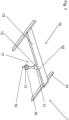
- FIG 3 shows the system 1 comprising the crane system 10 and the sensor box 20, which is mounted to the crane trolley 12.
- the system 1 is basically the same as described in figure 1 , but with a simplified illustration.
- the crane trolley 12 is moved by the drive train 11 along the crane bridge 13.
- the crane bridge 13 is supported by the crane runway rails 14.
- the crane system 10 further comprises the crane hook block 15 and the crane hook 16. Both can be used to transport equipment 105 (not shown in Fig.3 ) inside the industrial hall 100 (not shown in Fig.3 ) if necessary.
- This has the additional advantage that an exact position of the crane hook 16 and the transported equipment can be determined in a horizontal plane. This favours a remote control of the system 1.
- the crane hook block 15 and crane hook 16 can be omitted. This has the benefit that less components are necessary for the inspection and condition monitoring system 1. This results in a more cost effective system 1. Furthermore there is less risk of damaging equipment 105 (not shown in Fig.3 ) with the crane hook block 15 and crane hook 16 if the crane trolley 12 moves inside the industrial hall 100 (not shown in Fig.3 ).
- Figure 4 shows an alternative embodiment of arranging the sensor box 20 on the crane system 10.
- the system 1 is basically the same as described in figure 3 , with the difference that the sensor box 20 is mounted to the crane hook block 15.
- the crane hook block 15 is adapted to be moved up and down inside the industrial hall 100 (not shown in Fig.4 ).
- the sensor box 20 is also adapted to be moved up and down by the crane hook block 15. This has the benefit that the sensor box 20 moves in three dimensions and more areas and equipment 105 (not shown in Fig.4 ) can be detected.
- Figure 5 shows an alternative embodiment of arranging the sensor box 20 on the crane system 10.
- the system is basically the same as described in figure 3 , with the difference that the sensor box 20 is mounted to the crane hook 16. This has the benefit that the sensor box 20 can be mounted on demand to the crane system 10 if a routine inspection is due. This also reduces cost and simplifies installation of the sensor box 20 in pre-existing crane systems 10.
- FIG. 6 shows an exemplary structure of the arrangement of the sensor box 20.
- the system 1 comprises a rod structure 40 with a rod 41, a bottom end 42 and a top end 43.
- the rod 41 extends from the floor 103 of the industrial hall 100 to the ceiling 102 of the industrial hall 100.
- the rod structure 40 further comprises a mechanical channel 44 running along the floor 103 of the industrial hall 100.
- the mechanical channel 44 guides the rod 41 on its bottom end 42 with at least one wheel 45.
- the rod 41 is adapted to move between, for example two walls 101.
- the rod 41 is also adapted to move along one wall 101. But it can also move along more than one wall 101, for example, it can move along all of the four walls 101.
- the sensor box 20 is mounted to the rod 41 and the rod 41 is adapted to move the sensor box 20 up and down in the industrial hall 100. Therefore, the rod 41 and the mechanical channel 44 form a second rail system 47 and thus the sensor box 20 is adapted to move in a two or three dimensional space inside the industrial hall 100.
- the dashed lines visualize a possible trajectory of the sensor box 20.
- the movement of the rod 41 can be based on the existing crane system 10 in the industrial hall 100. This has the benefit that using pre-existing the crane system 10 is more cost efficient than installing a new movable system.
- the rod 41 can move through the industrial hall 100 without being limited to the area at the wall 101.
- the sensor box 20 is adapted to move in a three dimensional space.
- rod structure 40 can also be implemented on a structure other than a pre-existing infrastructure.
- Figure 7 shows an inspection and condition monitoring system 1.
- the system 1 is basically the same as described in figure 4 , with the difference that possible positions of X-, Y- and Z-direction position sensors 32 along the first rail system 17 are shown in dashed lines.
- the X-, Y- and Z-direction position sensors 32 are adapted for determining the position of the sensor box 20 inside the industrial hall 100 (not shown in Fig.7 ).
- the sensor box 20 is exemplarily mounted to the crane hook block 15. But it can also be mounted to the crane trolley 12, the crane hook 16 or on another part of the system 1.
- the X-, Y- and Z-direction position sensors 32 can also be used in the second rail system 47 of the rod structure 40 (not shown in Fig.7 ) according to figure 6 .
- first rail system 17 and/or the second rail system 47 comprising the X-, Y- and Z-direction position sensors 32 is that less sensors are mounted on the sensor box 20. This results in a lower weight of the sensor box 20. Furthermore less space is required and the additional space can be used for different sensors 30.
- Figure 8 shows a top view of the industrial hall 100.
- the equipment 105 is placed between, for example, four walls 101 of the industrial hall 100.
- the industrial hall 100 is not limited to four walls 101. It can also comprise less or more than four walls 101.
- the first rail system 17 and/or the second rail system 47 extend along a predetermined path (dashed line).
- the predetermined path is, for example, free from equipment 105 or it is cleared from an insulation point of view. For example, there are sufficiently low interfering electric, magnetic or electro-magnetic fields.
- the mechanical channel 44 follows the predetermined path on the floor 102 of the industrial hall 100.
- X-, Y- and Z-direction position sensors 32 can be arranged along the predetermined path.
- first rail system 17 and/or the second rail system 47 whose paths are limited to locations which are at safe distance from, for example, sensitive equipment or hazardous areas, prevent the sensor box 20 from obstruction or damage.
- monitoring may not be feasible during converter operation, e.g. between valves, they can be used when the converters are de-energized, e.g. to measure equipment position and insulation distances for commissioning, or to determine humidity thresholds and airflow around fiber bundles, thereby reducing dry-out times. Additionally, monitoring from certain locations such as the ceiling 102 or wall area may be possible even during operation, without risking insulation failure, such as infrared inspection, temperature, humidity, pressure and particle density monitoring.
- the high voltage clearance distances must be respected at all times, which reduces the effective scannable three dimensional space, restricting crane movement to, for example, the ceiling 102 or wall 101, and not between valves.
- the sensor box 20 can be moved as close as needed to the desired location near the valve structures.
- the only space restrictions are provided by e.g., busbars between the valve structure or between valves and wall bushings.
Landscapes
- Engineering & Computer Science (AREA)
- Architecture (AREA)
- Mechanical Engineering (AREA)
- Civil Engineering (AREA)
- Structural Engineering (AREA)
- Physics & Mathematics (AREA)
- General Physics & Mathematics (AREA)
- Arrangements For Transmission Of Measured Signals (AREA)
Abstract
Description
- The present disclosure relates to an inspection and condition monitoring system. The present disclosure further relates to a method for inspecting and condition monitoring of equipment in an industrial hall.
- A valve hall is a building which contains the valves of the converters of a high-voltage direct current (HVDC) plant. The valves can be of voltage source converter (VSC) type or line commutated converter (LCC) type. Voltage source converters (VSC) consist of insulated gate bipolar transistors (IGBT) and line commutated converters (LCC) consist of thyristors. The voltage source converters may either be supported by insulators in a standing position or hung from the ceiling of the valve hall. The latter requires a stronger ceiling structure or a dedicated truss structure, however the hall and the converters can better survive earthquakes compared to valve structures standing on the floor.
- A valve hall is equipped with heating and cooling equipment to control the temperature of power semiconductors. This includes thyristors, IGBTs and also potentially future types such as silicon carbide MOSFETs, etc. The control of the temperature is required not only for the power semiconductors, but also for all control and communication electronics in the valves and other auxiliary equipment in the valve hall. The valve hall also protects the valves from weather and pollution. Several valve assemblies, connected in series for the required terminal voltage, may be installed in the valve hall building.
- High voltage bushings are supported through the walls of the valve hall, to allow connections between the AC switchyard with grid transformers on the one side and the DC switchyard on the other. There is often an additional building beside the valve hall, which contains control electronics, equipment for valve cooling and valve monitoring, station service power distribution, and amenities for the plant workers.
- Because very high voltages are present while the converters are in operation, access to the valve halls is limited. The auxiliary control building may have windows to observe the valve hall, but these are normally not provided. Usually the converter is monitored by CCTV cameras for visual supervision. To protect communication systems from electromagnetic interference, valve hall buildings must have shielding installed to control emission of radio-frequency energy.
- Inspection and condition monitoring tools are expected to play an increasingly crucial role in optimizing and predicting the maintenance of HVDC converters.
- Inspection during commissioning or maintenance is mostly a manual process, requiring hundreds of man-hours for a converter.
- The ease of installing inspection and condition monitoring systems and their independent operation are of great importance to reduce the risk of adding equipment into a sensitive building, like an industrial hall.
- The utility model
CN210242988U discloses an infrared camera for a valve hall of a converter station. The infrared camera is attached to a track, which is mounted to the ceiling of the valve hall. - It is an object to avoid human interference inside an industrial hall while still increasing the quality of inspection and health monitoring of equipment and the environment in an industrial hall.
- This object is solved by the features of the independent claims. Advantageous embodiments are indicated in the dependent claims.
- Therefore, an inspection and health monitoring system inside an industrial hall, e.g. a valve hall, is provided. Furthermore a corresponding method of inspecting and health monitoring of equipment and/or the environment inside an industrial hall, for example in a valve hall, is provided. The industrial hall is delimited at least by a wall, a ceiling and a floor, enclosing a space containing equipment.
- The industrial hall is for example a valve hall, a cold storage warehouse, a foundry, a nuclear power plant, a cleanroom, an indoor substation, e.g. with gas insulated switchgear (GIS), or another facility with sensitive equipment and environment that needs monitoring.
- The system further comprises a drive train, which is located at a safe position below the ceiling of the industrial hall.
- The drive train is located at a safe position so that it is not affected by other equipment, electric fields or even electromagnetic interference. HVDC converters, for example, operate at voltages up to 1100 kV, hence clearance and creepage distances of up to several meters are necessary because of the high electric fields, i.e. both DC-fields and AC-fields. The system is not limited to HVDC converters, which operate at voltages up to 1100 kV. Higher voltages are also possible.
- Furthermore the system comprises a crane trolley, which is moved by the drive train, and a crane bridge, which supports the crane trolley.
- The crane trolley is also located at a safe position so that it is not affected by other equipment, electric fields or even electromagnetic interference.
- The system further comprises crane runway rails, adapted to support the crane bridge. Both the crane runway rails and the crane bridge form a first rail system, such that the crane trolley can move inside the industrial hall.
- The system further comprises at least one sensor box.
- The sensor box is attached to movable parts of the system and thus is movable inside the industrial hall.
- The system is easy to install, as it can be implemented onto a pre-existing infrastructure, which is a permanent installation, like a crane system used for valve installation. Other mobile platforms, like a rod structure, are also possible and the system is not limited to a crane system or a rod structure. The system can also be a temporary installation, for example a smaller overhead system could be installed for the sensor box, so that it can be used during converter maintenance or operation.
- The use of this inspection and health monitoring system has the advantage over unmanned ground vehicles, like robots, that the monitored area is larger. It is not limited to the floor. The advantage over unmanned aerial vehicles, like drones, is that a system using components of, for example, a crane system has a less restricted weight limit, which is associated with a limitation of the number and type of sensors used.
- Furthermore, robots and drones are typically used for scheduled inspections, and not for routine or continuous monitoring. For these inspections an operator is present, e.g. there is no or limited automation in the inspections performed with these technologies.
- Stationary wall or equipment mounted sensors either allow only for long-distance image sensing with limited resolution and line-of-sight or require a large number of sensors at critical installation locations.
- A movable sensor box allows for a better quality of inspection and health monitoring of the equipment and environment in an industrial hall. The sensor box reduces the need for a number of inspection and condition monitoring devices and also enables an automated inspection and monitoring system.
- The at least one sensor box is mounted to the crane trolley traveling along the crane bridge. Thus, the movement of the sensor box along the crane bridge and the crane runway rails enables a larger space inside the industrial hall to be scanned, even if it is not accessible on the ground.
- Furthermore the system comprises a crane hook block, which is linked to the crane trolley and which is adapted to move up and down in the industrial hall, wherein the at least one sensor box is mounted to the crane hook block.
- This enables a movement of the sensor box in three dimensions, which therefore enables an even larger space inside the industrial hall to be scanned. This results in a more detailed scan of the equipment and environment of the industrial hall.
- The system furthermore comprises a crane hook, which is linked to the crane hook block, wherein the at least one sensor box is attached to the crane hook. Using the crane hook as a mobile platform for the sensor box enables an on-demand scanning in three dimensions. This results in an ad-hoc scan if requested. In this case a position calibration procedure is needed when mounting the sensor box.
- Locating the drive train at a safe position at the wall of the industrial hall is advantageous if the space inside the industrial hall offers too little space for the sensor box or if the space is not accessible due to a hazardous environment or sensitive equipment. Thus, the drive train is limited to the area next to the wall. With this the sensor box is adapted to move in a two-dimensional space in a vertical plane at the wall of the industrial hall. For this purpose, for example, the crane bridge of a crane system is parked at the wall. Even if it is limited to this wall area, the advantage is that less sensors are needed to cover a larger area to be monitored.
- For this case an alternative structure can also be used to move the sensor box inside the industrial hall. For example, the system comprises a rod structure with a rod. The rod comprises a bottom end and a top end and extends from the floor of the industrial hall to the ceiling of the industrial hall. The rod structure further comprises a mechanical channel positioned on the floor of the industrial hall, forming a second rail system, such that the mechanical channel guides the rod on its bottom end with wheels. At the top end the rod is moved by, for example, the drive train. A different propulsion, like a mechanical drive, for example a gear drive, is also possible. The at least one sensor box is mounted to the rod. The rod is adapted to move the at least one sensor box up and down through the industrial hall.
- The use of the system with the rod has the benefit that a rod structure provides a more mechanically stable structure compared to, for example, a crane hook connected to a chain.
- The rod structure can also use a pre-existing crane system to move through the factory hall. Using the first rail system, for example, results in a more cost efficient inspection and health monitoring system.
- The at least one sensor box comprises a power supply, a data acquisition module, a data processing unit, a data storage, a data communication infrastructure and at least one sensor. Processing the data helps to reduce the communication effort by, for example, filtering, smoothing, averaging, feature detection, etc.
- The sensor box is equipped with one or a variety of different sensors to gather as much information as possible about the equipment and/or environment inside the industrial hall. A sensor can be a probing device, like a temperature sensor, a humidity sensor, a pressure sensor, a distance sensor, particulate matter sensor, sensors for gases to detect electrical discharges, electric probes, magnetic probes, electromagnetic probes, etc.
- The term sensor is expanded in the application to include cameras and microphones or any device that can detect signals or sense conditions. Cameras can be sensitive in the infrared region, ultraviolet region and in the region of visible light. Microphones can be sensitive to sound, ultrasound and infrasound. Microphones also include acoustic measurement and vibration monitoring.
- The at least one sensor is from a list of the following sensors:
- microphone
- camera
- electric probes, magnetic probes, electromagnetic probes
- temperature sensor
- humidity sensor
- particulate matter sensor
- gas sensor
- pressure sensor
- rangefinder
- LIDAR.
- This list is not exhaustive and not limited to the above mentioned sensors. With a variety of sensors different signals can be detected and premature warning is possible before extensive damage is caused in the industrial hall, or damaged equipment can be detected before it is beyond repair.
- It is also possible to use more than one sensor of one type. For example, two cameras can be used simultaneously for stereoscopic vision or inspection of multiple areas.
- Moreover, because of the possibility of including multiple sensors, these sensors can act redundantly, e.g. if a high temperature is sensed in equipment, infrared imaging can verify if the overheating is real, or if it is a sensor error. This has the potential to reduce false alarms from condition monitoring.
- The at least one sensor box comprises X-, Y- and Z-direction distance sensors for determining the exact position of the at least one sensor box inside the industrial hall. The tracking of the sensor box enables the equipment and environment to be scanned without human interference. With the exact position of the sensor box, different areas and equipment located in the areas can be distinguished and the sensed data can be analyzed and evaluated, for example with an automatic generated report, which comprises sensed data and locations of the sensor box.
- The at least one sensor box is adapted to be rotated about its yaw axis, its pitch axis and/or its roll axis. A rotatable sensor box gives the sensor box a larger field of view. For example, it is possible to rotate the sensor box around its yaw axis to scan the area in a 360° angle in the horizontal plane of the sensor box. Additionally, it is possible to rotate the sensor box around its pitch axis and/or around its roll axis to spot more difficult areas. The first rail system comprises X-, Y- and Z-direction position sensors for determining the position of the at least one sensor box inside the industrial hall. The position sensors can also be mounted on the second rail system. The position sensors mounted on the first and/or on the second rail system have the benefit that less sensors are installed on the sensor box. This helps to reduce the weight of the sensor box and leads to better energy conservation.
- The first rail system extends along a predetermined path. The second rail system can also extend along a predetermined path. This has the benefit that a rail system, whose path is limited to locations which are at a safe distance from, for example, sensitive equipment or hazardous areas, prevents the sensor box from being obstructed or damaged. Nevertheless this still enables an increase in the quality of inspection and health monitoring of the equipment and environment of the industrial hall, like a valve hall.
- By electrically insulating the whole system or individual parts of the system, even if the sensor box or a part of the system comes close to electrical equipment it can be saved from damage, for example due to an electric arc or a flashover.
- According to a method for inspecting and condition monitoring of equipment in an industrial hall, the following steps are performed:
- moving the at least one sensor box inside the industrial hall,
- scanning the equipment and/or the environment of the industrial hall using the at least one sensor,
- acquiring data of the scanned equipment and/or environment with the data acquisition module,
- processing the acquired data with a data processing unit,
- storing of the acquired data created during scanning inside the data storage,
- transferring of the stored data with the data communication infrastructure to an analytics system.
- The transferring of the stored data happens continuously and/or at defined positions. A continuous transfer of the stored data ensures that the condition of the equipment and environment of the industrial hall is monitored and immediately detected. An operator can monitor the data in real-time and decide to focus on a specific location if some anomaly is detected. Thus, malfunctions can be noticed before they become severe.
- Furthermore the transfer of the stored data at defined positions enables a data transfer, for example, at a recharging station for the sensor box. Thus, the time during recharging can be used for transferring data. The transfer can also happen at locations which are safe from, for example, electromagnetic fields or other interfering signals.
- For transferring the stored data at defined positions, the sensor box can be either switched on or switched off. Switched on constitutes an operating mode in which the sensor box is using its sensors. Switched off constitutes an operating mode in which the sensor box does not use its sensors.
- Furthermore the transferring of the stored data happens via a wired connection and/or via a wireless connection. A wired connection can be any connection using a cable,for example, copper cables, fiber optic cables or cables made from other materials, with or without shielding. This has the benefit that interference signals have less impact on the transfer of the stored data.
- A wireless connection can be any connection using radio communication. For example wireless local area network (WLAN), Bluetooth or cell phone networks. This has the benefit of avoiding the necessity of introducing cables into the industrial hall and thus saving installation costs.
- The accompanying figures are included to provide a further understanding. In the figures, elements of the same structure and/or functionality may be referenced by the same reference signs. It is to be understood that the embodiments shown in the figures are illustrative representations and are not necessarily drawn to scale.
- Figure 1
- is a perspective view of an inspection and monitoring system inside an industrial hall according to an embodiment,
- Figure 2
- is a perspective view of a sensor box,
- Figure 3
- is another perspective view of an embodiment according to
figure 1 of the mounting of the sensor box according tofigure 2 , - Figure 4
- is a perspective view of another embodiment of the mounting of the sensor box according to
figure 2 , - Figure 5
- is a perspective view of another embodiment of the mounting of the sensor box according to
figure 2 , - Figure 6
- is a perspective view of an exemplary mounting structure for the sensor box according to
figure 2 , - Figure 7
- is a perspective view of an embodiment of a rail system used in the system according to
Figures 1 and3 to 6 , - Figure 8
- is a top view of the used path of the sensor box according to
figure 2 . -
Figure 1 shows an inspection andcondition monitoring system 1 comprising anindustrial hall 100, for example a valve hall. Theindustrial hall 100 comprises, for example, fourwalls 101, aceiling 102 and afloor 103 enclosing aspace 104. Theindustrial hall 100 is delimited by at least awall 101, but can comprise more than onewall 101 and its layout can have any shape. Various equipment 105 (not shown) can be inside theindustrial hall 100. Thesystem 1 furthermore comprises acrane system 10, which is positioned inside thefactory hall 100, and asensor box 20. Thecrane system 10 comprises adrive train 11, acrane trolley 12, acrane bridge 13, crane runway rails 14, acrane hook block 15 and acrane hook 16. - The
crane system 10 can be already installed during commissioning or can be installed if the need for inspection and condition monitoring arises. Thecrane system 10 can be a temporary or a permanent fixture used for installing, for example, valves in a valve hall. In the first case, thesystem 1 is intended to check installation and commissioning of the valve hall. In the second case, thesystem 1 can additionally be used to check conditions during shutdown, maintenance, and operation, while having a restricted range of movement to respect insulation distances. In the case of a temporary crane for installation, a smaller overhead system could be installed for thesensor box 20 so that it can be used during converter maintenance or operation. - The
drive train 11 moves thecrane trolley 12, which is supported by thecrane bridge 13. Thecrane bridge 13 is supported by the crane runway rails 14 and moves forward and backward in a horizontal plane inside theindustrial hall 100. Thecrane bridge 13 and the crane runway rails 14 form afirst rail system 17, which enables thecrane trolley 12 to move inside theindustrial hall 100 in a horizontal plane perpendicular to the movement of thecrane bridge 13. Thecrane hook block 15 is linked to thecrane trolley 12 and follows its movement. A possible linking device, for example, is a chain. Besides the chain approach, another option is to use another device to change the vertical position of thesensor box 20, for example, by a telescope-like positioning device that is not susceptible to internal rotation and oscillation. - Additionally, the
crane hook block 15 is adapted to move up and down inside theindustrial hall 100. Together with thefirst rail system 17, thecrane hook block 15 is adapted to move in a three dimensional space. Thecrane hook 16 is in turn linked to thecrane hook block 15 and follows the movement of thecrane hook block 15. Thesensor box 20 can be mounted anywhere on thesystem 1 as long as it is movable. - Exemplarily, the
sensor box 20 infigure 1 andfigure 3 is attached to thecrane trolley 12, but it is not limited to thecrane trolley 12. - The
drive train 11 is positioned at a safe position below theceiling 102 to mitigate interferences from, for example, electromagnetic fields. A safe position can also be an area inside thespace 104 which is safe from a hazardous environment or equipment. Hazardous environment and equipment can be characterized, for example, by electromagnetic interferences, a high temperature or high radiation. Even justequipment 105 inside theindustrial hall 100 can lead to damage to thesystem 1 or a part of thesystem 1, like thesensor box 20, due to a collision. A safe position can also be next to or at thewall 101, if there is sufficient distance to theequipment 105 or to defined areas. In this case, thecrane system 10 takes up a position at thewall 101. Thesensor box 20 can then be moved either by thecrane bridge 13 along thewall 101 or it can be moved by thecrane trolley 12 along thewall 101. Thesensor box 20 can be moved together with thecrane hook block 15 or thecrane hook 16 in a two-dimensional space in a vertical plane. -
Figure 2 shows thesensor box 20 with apower supply 21, adata acquisition module 22, adata processing unit 28, adata storage 23 and adata communication infrastructure 24. Thesensor box 20 comprises at least onesensor 30. In this example thesensor box 20 comprises foursensors 30, but it can have more or less than foursensors 30, and a X-, Y- and Z-direction distance sensor 31, which is optional. Different kinds of sensors are possible to sense different parameters, like temperature, particle matter, humidity, pressure, gases, electric fields, magnetic fields, electromagnetic fields, etc. A sensor can be any sensing device, like a camera or a microphone. Such a camera can detect light of any kind. Infrared, ultraviolet and visible light. Thesensor box 20 can also comprise more than one camera and use it, for example, for stereoscopic vision or inspection of multiple areas simultaneously. - This list is not exhaustive and not limited to the above mentioned metrics.
- When mounted, the
sensor box 20 is adapted to be rotated about ayaw axis 25, apitch axis 26 and/or aroll axis 27. This gives the sensor box 20 a larger field of view and enables thesensor box 20 to detect areas and equipment 105 (not shown inFig.2 ) inside the industrial hall 100 (not shown inFig.2 ), which are difficult to see otherwise. - The
power supply 21 of thesensor box 20 can be a primary or secondary battery, which can be recharged. It is also possible to supply energy to thesensor box 20 with a power cable. -
Figure 3 shows thesystem 1 comprising thecrane system 10 and thesensor box 20, which is mounted to thecrane trolley 12. Thesystem 1 is basically the same as described infigure 1 , but with a simplified illustration. Thecrane trolley 12 is moved by thedrive train 11 along thecrane bridge 13. Thecrane bridge 13 is supported by the crane runway rails 14. Thecrane system 10 further comprises thecrane hook block 15 and thecrane hook 16. Both can be used to transport equipment 105 (not shown inFig.3 ) inside the industrial hall 100 (not shown inFig.3 ) if necessary. This has the additional advantage that an exact position of thecrane hook 16 and the transported equipment can be determined in a horizontal plane. This favours a remote control of thesystem 1. - If a scan of the
sensor box 20 in only two dimensions is required, thecrane hook block 15 andcrane hook 16 can be omitted. This has the benefit that less components are necessary for the inspection andcondition monitoring system 1. This results in a more costeffective system 1. Furthermore there is less risk of damaging equipment 105 (not shown inFig.3 ) with thecrane hook block 15 andcrane hook 16 if thecrane trolley 12 moves inside the industrial hall 100 (not shown inFig.3 ). -
Figure 4 shows an alternative embodiment of arranging thesensor box 20 on thecrane system 10. Thesystem 1 is basically the same as described infigure 3 , with the difference that thesensor box 20 is mounted to thecrane hook block 15. Thecrane hook block 15 is adapted to be moved up and down inside the industrial hall 100 (not shown inFig.4 ). Thus, thesensor box 20 is also adapted to be moved up and down by thecrane hook block 15. This has the benefit that thesensor box 20 moves in three dimensions and more areas and equipment 105 (not shown inFig.4 ) can be detected. -
Figure 5 shows an alternative embodiment of arranging thesensor box 20 on thecrane system 10. The system is basically the same as described infigure 3 , with the difference that thesensor box 20 is mounted to thecrane hook 16. This has the benefit that thesensor box 20 can be mounted on demand to thecrane system 10 if a routine inspection is due. This also reduces cost and simplifies installation of thesensor box 20 inpre-existing crane systems 10. -
Figure 6 shows an exemplary structure of the arrangement of thesensor box 20. Thesystem 1 comprises arod structure 40 with arod 41, abottom end 42 and atop end 43. Therod 41 extends from thefloor 103 of theindustrial hall 100 to theceiling 102 of theindustrial hall 100. Therod structure 40 further comprises amechanical channel 44 running along thefloor 103 of theindustrial hall 100. Themechanical channel 44 guides therod 41 on itsbottom end 42 with at least onewheel 45. Thus, therod 41 is adapted to move between, for example twowalls 101. Therod 41 is also adapted to move along onewall 101. But it can also move along more than onewall 101, for example, it can move along all of the fourwalls 101. Thesensor box 20 is mounted to therod 41 and therod 41 is adapted to move thesensor box 20 up and down in theindustrial hall 100. Therefore, therod 41 and themechanical channel 44 form asecond rail system 47 and thus thesensor box 20 is adapted to move in a two or three dimensional space inside theindustrial hall 100. The dashed lines visualize a possible trajectory of thesensor box 20. - The movement of the
rod 41 can be based on the existingcrane system 10 in theindustrial hall 100. This has the benefit that using pre-existing thecrane system 10 is more cost efficient than installing a new movable system. - For this purpose the
top end 43 can be attached to the crane trolley 12 (not shown inFig.6 ), to the crane bridge 13 (not shown inFig.6 ) or the crane runway rails 14 (not shown inFig.6 ). Therod 41 is driven, for example, by the drive train 11 (not shown inFig.6 ). A different propulsion, like a mechanical drive, for example a gear drive, is also possible. - Alternatively the
rod 41 can move through theindustrial hall 100 without being limited to the area at thewall 101. Thus, thesensor box 20 is adapted to move in a three dimensional space. - Furthermore the
rod structure 40 can also be implemented on a structure other than a pre-existing infrastructure. -
Figure 7 shows an inspection andcondition monitoring system 1. Thesystem 1 is basically the same as described infigure 4 , with the difference that possible positions of X-, Y- and Z-direction position sensors 32 along thefirst rail system 17 are shown in dashed lines. The X-, Y- and Z-direction position sensors 32 are adapted for determining the position of thesensor box 20 inside the industrial hall 100 (not shown inFig.7 ). - In this case the
sensor box 20 is exemplarily mounted to thecrane hook block 15. But it can also be mounted to thecrane trolley 12, thecrane hook 16 or on another part of thesystem 1. - The X-, Y- and Z-
direction position sensors 32 can also be used in thesecond rail system 47 of the rod structure 40 (not shown inFig.7 ) according tofigure 6 . - The benefit of the
first rail system 17 and/or thesecond rail system 47 comprising the X-, Y- and Z-direction position sensors 32 is that less sensors are mounted on thesensor box 20. This results in a lower weight of thesensor box 20. Furthermore less space is required and the additional space can be used fordifferent sensors 30. -
Figure 8 shows a top view of theindustrial hall 100. Theequipment 105 is placed between, for example, fourwalls 101 of theindustrial hall 100. Theindustrial hall 100 is not limited to fourwalls 101. It can also comprise less or more than fourwalls 101. Thefirst rail system 17 and/or thesecond rail system 47 extend along a predetermined path (dashed line). The predetermined path is, for example, free fromequipment 105 or it is cleared from an insulation point of view. For example, there are sufficiently low interfering electric, magnetic or electro-magnetic fields. In the case of therod structure 40, themechanical channel 44 follows the predetermined path on thefloor 102 of theindustrial hall 100. X-, Y- and Z-direction position sensors 32 can be arranged along the predetermined path. - This has the benefit that the
first rail system 17 and/or thesecond rail system 47, whose paths are limited to locations which are at safe distance from, for example, sensitive equipment or hazardous areas, prevent thesensor box 20 from obstruction or damage. - While the disclosure is amenable to various modifications and alternative forms, specifics thereof have been shown by way of example in the figures and will be described in detail. It should be understood, however, that the intention is not to limit the disclosure to the particular embodiments described. On the contrary, the intention is to cover all modifications, equivalents, and alternatives falling within the scope of the disclosure defined by the appended claims.
- The embodiments shown in the
Figures 1 to 8 as stated represent exemplary embodiments of the improved arrangement and method; therefore, they do not constitute a complete list of all embodiments according to the improved arrangement and method. Actual arrangements and methods may vary from the embodiments shown in terms of arrangements, devices, for example. - While some types of monitoring may not be feasible during converter operation, e.g. between valves, they can be used when the converters are de-energized, e.g. to measure equipment position and insulation distances for commissioning, or to determine humidity thresholds and airflow around fiber bundles, thereby reducing dry-out times. Additionally, monitoring from certain locations such as the
ceiling 102 or wall area may be possible even during operation, without risking insulation failure, such as infrared inspection, temperature, humidity, pressure and particle density monitoring. - If the scanning procedure is performed during converter operation, the high voltage clearance distances must be respected at all times, which reduces the effective scannable three dimensional space, restricting crane movement to, for example, the
ceiling 102 orwall 101, and not between valves. During a de-energized state of the converter, e.g. during installation, commissioning, or maintenance periods, thesensor box 20 can be moved as close as needed to the desired location near the valve structures. The only space restrictions are provided by e.g., busbars between the valve structure or between valves and wall bushings. - By electrically insulating the
whole system 1 or individual parts of thesystem 1, even if thesensor box 20 or a part of thecrane system 10 comes close to electrical equipment it can be saved from damage, for example due to an electric arc or a flashover. -
- 1
- condition monitoring system
- 10
- crane system
- 11
- drive train
- 12
- crane trolley
- 13
- crane bridge
- 14
- crane runway rails
- 15
- crane hook block
- 16
- crane hook
- 17
- first rail system
- 20
- sensor box
- 21
- power supply
- 22
- data acquisition module
- 23
- data storage
- 24
- data communication infrastructure
- 25
- yaw axis of the sensor box
- 26
- pitch axis of the sensor box
- 27
- roll axis of the sensor box
- 28
- data processing unit
- 30
- sensor
- 31
- X-, Y- and Z-direction distance sensors
- 32
- X-, Y- and Z-direction position sensors
- 40
- rod structure
- 41
- rod
- 42
- bottom end
- 43
- top end
- 44
- mechanical channel
- 45
- wheel
- 47
- second rail system
- 50
- analytics system
- 100
- industrial hall
- 101
- wall
- 102
- ceiling
- 103
- floor
- 104
- enclosed space
- 105
- equipment
Claims (15)
- An inspection and condition monitoring system (1), comprising:- an industrial hall (100) delimited at least by a wall (101), a ceiling (102) and a floor (103), enclosing a space (104) containing equipment (105),- a drive train (11), which is located at a safe position below the ceiling (102) of the industrial hall (100),- a crane trolley (12), which is moved by the drive train (11),- a crane bridge (13), which supports the crane trolley (12),- crane runway rails (14), adapted to support the crane bridge (13), both forming a first rail system (17) such that the crane trolley (12) can move inside the industrial hall (100), and- at least one sensor box (20).
- System (1) according to claim 1, wherein the at least one sensor box (20) is mounted to the crane trolley (12) traveling along the crane bridge (13).
- System (1) according to one of the preceding claims, comprising- a crane hook block (15), which is linked to the crane trolley (12) and which is adapted to move up and down in the industrial hall (100), wherein the at least one sensor box (20) is mounted to the crane hook block (15).
- System (1) according to one of the preceding claims, comprising- a crane hook (16), which is linked to the crane hook block (15), wherein the at least one sensor box (20) is attached to the crane hook (16).
- System (1) according to one of the preceding claims,
wherein the drive train (11) is located at a safe position at the wall (101) of the industrial hall (100). - System (1) according to one of the preceding claims,
wherein the at least one sensor box (20) comprises- a power supply (21),- a data acquisition module (22),- a data processing unit (28),- a data storage (23)- a data communication infrastructure (24) and- at least one sensor (30). - System (1) according to claim 6, wherein the at least one sensor (30) is from a list of the following sensors (30):- microphone- camera- electric probes- magnetic probes- electromagnetic probes- temperature sensor- humidity sensor- particulate matter sensor- gas sensor- pressure sensor- rangefinder- LIDAR.
- System (1) according to one of the preceding claims,
wherein the at least one sensor box (20) comprises X-, Y- and Z-direction distance sensors (31) for determining the exact position of the at least one sensor box (20) inside the industrial hall (100). - System (1) according to one of the preceding claims,
wherein the at least one sensor box (20) is adapted to be rotated about its yaw axis (25), its pitch axis (26) and/or its roll axis (27). - System (1) according to one of the preceding claims,
wherein the first rail system (17) comprises X-, Y- and Z-direction position sensors (32) for determining the position of the at least one sensor box (20) inside the industrial hall (100). - System (1) according to one of the preceding claims,
wherein the first rail system (17) extends along a predetermined path. - System (1) according to one of the preceding claims,
wherein the system (1) is electrically insulated. - A method for inspecting and condition monitoring of equipment (105) in an industrial hall (100), comprising the following steps:- moving the at least one sensor box (20) inside the industrial hall (100),- scanning the equipment (105) and/or the environment of the industrial hall (100) using the at least one sensor (30),- acquiring data of the scanned equipment (105) and/or environment with the data acquisition module (22),- processing the acquired data with a data processing unit (28),- storing of the processed data created during scanning inside the data storage (23),- transferring of the stored data with the data communication infrastructure (24) to an analytics system (50) .
- Method according to claim 13, wherein the transferring of the stored data happens- continuously and/or- at defined positions.
- Method according to claim 14, wherein transferring of the stored data happens- via a wired connection and/or- via a wireless connection.
Priority Applications (2)
| Application Number | Priority Date | Filing Date | Title |
|---|---|---|---|
| EP23160192.3A EP4428086A1 (en) | 2023-03-06 | 2023-03-06 | Movable platform for inspection and condition monitoring of a high-voltage valve hall |
| CN202410247195.3A CN118597988A (en) | 2023-03-06 | 2024-03-05 | Mobile platform for inspection and condition monitoring of high-pressure valve halls |
Applications Claiming Priority (1)
| Application Number | Priority Date | Filing Date | Title |
|---|---|---|---|
| EP23160192.3A EP4428086A1 (en) | 2023-03-06 | 2023-03-06 | Movable platform for inspection and condition monitoring of a high-voltage valve hall |
Publications (1)
| Publication Number | Publication Date |
|---|---|
| EP4428086A1 true EP4428086A1 (en) | 2024-09-11 |
Family
ID=85505560
Family Applications (1)
| Application Number | Title | Priority Date | Filing Date |
|---|---|---|---|
| EP23160192.3A Pending EP4428086A1 (en) | 2023-03-06 | 2023-03-06 | Movable platform for inspection and condition monitoring of a high-voltage valve hall |
Country Status (2)
| Country | Link |
|---|---|
| EP (1) | EP4428086A1 (en) |
| CN (1) | CN118597988A (en) |
Citations (7)
| Publication number | Priority date | Publication date | Assignee | Title |
|---|---|---|---|---|
| US20140081536A1 (en) * | 2010-02-01 | 2014-03-20 | Trimble Navigation Limited | Lifting device efficient load delivery, load monitoring, collision avoidance, and load hazard avoidance |
| US20170369288A1 (en) * | 2016-06-22 | 2017-12-28 | The Boeing Company | Systems and methods for object guidance and collision avoidance |
| CN207361617U (en) * | 2017-10-30 | 2018-05-15 | 鞍山师范学院 | A kind of wireless bridge crane walking safety control systems of 2.4G |
| CN207748759U (en) * | 2017-11-21 | 2018-08-21 | 成都纵远机械设备有限公司 | A kind of bridge crane |
| CN109019347A (en) * | 2018-10-18 | 2018-12-18 | 东北大学 | A kind of bridge crane automatic control system |
| US20190233259A1 (en) * | 2017-12-01 | 2019-08-01 | David R. Cordell & Associates, Inc. | Self-Maintaining Crane System within a Hostile Environment |
| CN210242988U (en) | 2019-07-12 | 2020-04-03 | 中国南方电网有限责任公司超高压输电公司广州局 | Infrared mobile temperature measurement monitoring device for converter station valve hall |
-
2023
- 2023-03-06 EP EP23160192.3A patent/EP4428086A1/en active Pending
-
2024
- 2024-03-05 CN CN202410247195.3A patent/CN118597988A/en active Pending
Patent Citations (7)
| Publication number | Priority date | Publication date | Assignee | Title |
|---|---|---|---|---|
| US20140081536A1 (en) * | 2010-02-01 | 2014-03-20 | Trimble Navigation Limited | Lifting device efficient load delivery, load monitoring, collision avoidance, and load hazard avoidance |
| US20170369288A1 (en) * | 2016-06-22 | 2017-12-28 | The Boeing Company | Systems and methods for object guidance and collision avoidance |
| CN207361617U (en) * | 2017-10-30 | 2018-05-15 | 鞍山师范学院 | A kind of wireless bridge crane walking safety control systems of 2.4G |
| CN207748759U (en) * | 2017-11-21 | 2018-08-21 | 成都纵远机械设备有限公司 | A kind of bridge crane |
| US20190233259A1 (en) * | 2017-12-01 | 2019-08-01 | David R. Cordell & Associates, Inc. | Self-Maintaining Crane System within a Hostile Environment |
| CN109019347A (en) * | 2018-10-18 | 2018-12-18 | 东北大学 | A kind of bridge crane automatic control system |
| CN210242988U (en) | 2019-07-12 | 2020-04-03 | 中国南方电网有限责任公司超高压输电公司广州局 | Infrared mobile temperature measurement monitoring device for converter station valve hall |
Also Published As
| Publication number | Publication date |
|---|---|
| CN118597988A (en) | 2024-09-06 |
Similar Documents
| Publication | Publication Date | Title |
|---|---|---|
| US8666553B2 (en) | Line inspection robot and system | |
| KR101948523B1 (en) | Managing method of substation facilities utilzing a robot system | |
| KR0148342B1 (en) | Abnormality system and its method for a high voltage power supply apparatus | |
| CN202735798U (en) | Cable channel intelligent inspection robot monitoring application system | |
| CN102955467B (en) | Sensor-swarm environmental event detection method and system | |
| US8660698B2 (en) | Line inspection robot and system | |
| CN113092494B (en) | Inspection robot and intelligent detection method for train tunnel structure diseases | |
| KR101954902B1 (en) | Stability inspection system of power transmission tower using drone | |
| Silva et al. | On-rail solution for autonomous inspections in electrical substations | |
| CN118394103A (en) | Intelligent inspection operation management system for unmanned aerial vehicle of power indoor station | |
| CN119270832B (en) | Intelligent autonomous inspection system for unmanned aerial vehicle of power distribution line | |
| US8706340B2 (en) | Underground utility vault inspection system and method | |
| CN117214771A (en) | Inter-turn short circuit fault location estimation method and system based on detection coil array | |
| Shengfang et al. | Research on the AGV based robot system used in substation inspection | |
| GB2600986A (en) | Balance weight monitoring | |
| CN121230883A (en) | Intelligent Early Warning Method and Monitoring System for Substations Based on Infrared Imaging | |
| CN118597988A (en) | Mobile platform for inspection and condition monitoring of high-pressure valve halls | |
| CN204086412U (en) | A kind of electric device maintenance streamline based on automatical pilot transportation vehicle | |
| JP2020048258A (en) | Electrical facility check system | |
| CA2745815C (en) | Line inspection robot and system | |
| TWI822099B (en) | Current measurement system and method | |
| RU24981U1 (en) | MOBILE CONTROL POST | |
| Cao et al. | Unmanned intelligent installation for indoor power electrical equipment based on machine vision and internet-of-things | |
| Jisha et al. | Autonomous Inspection of High Tension Transmission Lines Using Robotics | |
| Schutte et al. | Overview of the CU HVDC valves and control system upgrade project |
Legal Events
| Date | Code | Title | Description |
|---|---|---|---|
| PUAI | Public reference made under article 153(3) epc to a published international application that has entered the european phase |
Free format text: ORIGINAL CODE: 0009012 |
|
| STAA | Information on the status of an ep patent application or granted ep patent |
Free format text: STATUS: THE APPLICATION HAS BEEN PUBLISHED |
|
| AK | Designated contracting states |
Kind code of ref document: A1 Designated state(s): AL AT BE BG CH CY CZ DE DK EE ES FI FR GB GR HR HU IE IS IT LI LT LU LV MC ME MK MT NL NO PL PT RO RS SE SI SK SM TR |
|
| RIN1 | Information on inventor provided before grant (corrected) |
Inventor name: FAIRBROTHER, ANDREW Inventor name: LUVISOTTO, MICHELE Inventor name: CHEN, NAN Inventor name: SCHUDERER, JUERGEN Inventor name: COTTET, DIDIER |
|
| STAA | Information on the status of an ep patent application or granted ep patent |
Free format text: STATUS: REQUEST FOR EXAMINATION WAS MADE |
|
| 17P | Request for examination filed |
Effective date: 20250227 |
|
| STAA | Information on the status of an ep patent application or granted ep patent |
Free format text: STATUS: EXAMINATION IS IN PROGRESS |
|
| 17Q | First examination report despatched |
Effective date: 20250508 |