EP4428079A1 - Reference point marking apparatus and roll map generating apparatus - Google Patents
Reference point marking apparatus and roll map generating apparatus Download PDFInfo
- Publication number
- EP4428079A1 EP4428079A1 EP23860803.8A EP23860803A EP4428079A1 EP 4428079 A1 EP4428079 A1 EP 4428079A1 EP 23860803 A EP23860803 A EP 23860803A EP 4428079 A1 EP4428079 A1 EP 4428079A1
- Authority
- EP
- European Patent Office
- Prior art keywords
- electrode
- pattern
- marking machine
- pattern electrode
- marking
- Prior art date
- Legal status (The legal status is an assumption and is not a legal conclusion. Google has not performed a legal analysis and makes no representation as to the accuracy of the status listed.)
- Pending
Links
Images


Classifications
-
- H—ELECTRICITY
- H01—ELECTRIC ELEMENTS
- H01M—PROCESSES OR MEANS, e.g. BATTERIES, FOR THE DIRECT CONVERSION OF CHEMICAL ENERGY INTO ELECTRICAL ENERGY
- H01M4/00—Electrodes
- H01M4/02—Electrodes composed of, or comprising, active material
- H01M4/04—Processes of manufacture in general
-
- H—ELECTRICITY
- H01—ELECTRIC ELEMENTS
- H01M—PROCESSES OR MEANS, e.g. BATTERIES, FOR THE DIRECT CONVERSION OF CHEMICAL ENERGY INTO ELECTRICAL ENERGY
- H01M4/00—Electrodes
- H01M4/02—Electrodes composed of, or comprising, active material
- H01M4/04—Processes of manufacture in general
- H01M4/0402—Methods of deposition of the material
- H01M4/0404—Methods of deposition of the material by coating on electrode collectors
-
- B—PERFORMING OPERATIONS; TRANSPORTING
- B65—CONVEYING; PACKING; STORING; HANDLING THIN OR FILAMENTARY MATERIAL
- B65H—HANDLING THIN OR FILAMENTARY MATERIAL, e.g. SHEETS, WEBS, CABLES
- B65H37/00—Article or web delivery apparatus incorporating devices for performing specified auxiliary operations
-
- B—PERFORMING OPERATIONS; TRANSPORTING
- B23—MACHINE TOOLS; METAL-WORKING NOT OTHERWISE PROVIDED FOR
- B23K—SOLDERING OR UNSOLDERING; WELDING; CLADDING OR PLATING BY SOLDERING OR WELDING; CUTTING BY APPLYING HEAT LOCALLY, e.g. FLAME CUTTING; WORKING BY LASER BEAM
- B23K26/00—Working by laser beam, e.g. welding, cutting or boring
- B23K26/18—Working by laser beam, e.g. welding, cutting or boring using absorbing layers on the workpiece, e.g. for marking or protecting purposes
-
- B—PERFORMING OPERATIONS; TRANSPORTING
- B41—PRINTING; LINING MACHINES; TYPEWRITERS; STAMPS
- B41J—TYPEWRITERS; SELECTIVE PRINTING MECHANISMS, i.e. MECHANISMS PRINTING OTHERWISE THAN FROM A FORME; CORRECTION OF TYPOGRAPHICAL ERRORS
- B41J11/00—Devices or arrangements of selective printing mechanisms, e.g. ink-jet printers or thermal printers, for supporting or handling copy material in sheet or web form
- B41J11/0095—Detecting means for copy material, e.g. for detecting or sensing presence of copy material or its leading or trailing end
-
- B—PERFORMING OPERATIONS; TRANSPORTING
- B41—PRINTING; LINING MACHINES; TYPEWRITERS; STAMPS
- B41J—TYPEWRITERS; SELECTIVE PRINTING MECHANISMS, i.e. MECHANISMS PRINTING OTHERWISE THAN FROM A FORME; CORRECTION OF TYPOGRAPHICAL ERRORS
- B41J15/00—Devices or arrangements of selective printing mechanisms, e.g. ink-jet printers or thermal printers, specially adapted for supporting or handling copy material in continuous form, e.g. webs
- B41J15/04—Supporting, feeding, or guiding devices; Mountings for web rolls or spindles
- B41J15/08—Supporting, feeding, or guiding devices; Mountings for web rolls or spindles characterised by being applied to printers having transversely- moving carriages
-
- B—PERFORMING OPERATIONS; TRANSPORTING
- B41—PRINTING; LINING MACHINES; TYPEWRITERS; STAMPS
- B41J—TYPEWRITERS; SELECTIVE PRINTING MECHANISMS, i.e. MECHANISMS PRINTING OTHERWISE THAN FROM A FORME; CORRECTION OF TYPOGRAPHICAL ERRORS
- B41J3/00—Typewriters or selective printing or marking mechanisms characterised by the purpose for which they are constructed
- B41J3/407—Typewriters or selective printing or marking mechanisms characterised by the purpose for which they are constructed for marking on special material
-
- B—PERFORMING OPERATIONS; TRANSPORTING
- B41—PRINTING; LINING MACHINES; TYPEWRITERS; STAMPS
- B41J—TYPEWRITERS; SELECTIVE PRINTING MECHANISMS, i.e. MECHANISMS PRINTING OTHERWISE THAN FROM A FORME; CORRECTION OF TYPOGRAPHICAL ERRORS
- B41J3/00—Typewriters or selective printing or marking mechanisms characterised by the purpose for which they are constructed
- B41J3/60—Typewriters or selective printing or marking mechanisms characterised by the purpose for which they are constructed for printing on both faces of the printing material
-
- B—PERFORMING OPERATIONS; TRANSPORTING
- B65—CONVEYING; PACKING; STORING; HANDLING THIN OR FILAMENTARY MATERIAL
- B65H—HANDLING THIN OR FILAMENTARY MATERIAL, e.g. SHEETS, WEBS, CABLES
- B65H26/00—Warning or safety devices, e.g. automatic fault detectors, stop-motions, for web-advancing mechanisms
- B65H26/02—Warning or safety devices, e.g. automatic fault detectors, stop-motions, for web-advancing mechanisms responsive to presence of irregularities in running webs
-
- B—PERFORMING OPERATIONS; TRANSPORTING
- B65—CONVEYING; PACKING; STORING; HANDLING THIN OR FILAMENTARY MATERIAL
- B65H—HANDLING THIN OR FILAMENTARY MATERIAL, e.g. SHEETS, WEBS, CABLES
- B65H29/00—Delivering or advancing articles from machines; Advancing articles to or into piles
-
- B—PERFORMING OPERATIONS; TRANSPORTING
- B65—CONVEYING; PACKING; STORING; HANDLING THIN OR FILAMENTARY MATERIAL
- B65H—HANDLING THIN OR FILAMENTARY MATERIAL, e.g. SHEETS, WEBS, CABLES
- B65H43/00—Use of control, checking, or safety devices, e.g. automatic devices comprising an element for sensing a variable
- B65H43/04—Use of control, checking, or safety devices, e.g. automatic devices comprising an element for sensing a variable detecting, or responding to, presence of faulty articles
-
- G—PHYSICS
- G01—MEASURING; TESTING
- G01N—INVESTIGATING OR ANALYSING MATERIALS BY DETERMINING THEIR CHEMICAL OR PHYSICAL PROPERTIES
- G01N21/00—Investigating or analysing materials by the use of optical means, i.e. using sub-millimetre waves, infrared, visible or ultraviolet light
- G01N21/84—Systems specially adapted for particular applications
- G01N21/88—Investigating the presence of flaws or contamination
- G01N21/8851—Scan or image signal processing specially adapted therefor, e.g. for scan signal adjustment, for detecting different kinds of defects, for compensating for structures, markings, edges
-
- G—PHYSICS
- G01—MEASURING; TESTING
- G01N—INVESTIGATING OR ANALYSING MATERIALS BY DETERMINING THEIR CHEMICAL OR PHYSICAL PROPERTIES
- G01N21/00—Investigating or analysing materials by the use of optical means, i.e. using sub-millimetre waves, infrared, visible or ultraviolet light
- G01N21/84—Systems specially adapted for particular applications
- G01N21/88—Investigating the presence of flaws or contamination
- G01N21/89—Investigating the presence of flaws or contamination in moving material, e.g. running paper or textiles
- G01N21/8914—Investigating the presence of flaws or contamination in moving material, e.g. running paper or textiles characterised by the material examined
-
- H—ELECTRICITY
- H01—ELECTRIC ELEMENTS
- H01M—PROCESSES OR MEANS, e.g. BATTERIES, FOR THE DIRECT CONVERSION OF CHEMICAL ENERGY INTO ELECTRICAL ENERGY
- H01M10/00—Secondary cells; Manufacture thereof
- H01M10/04—Construction or manufacture in general
-
- H—ELECTRICITY
- H01—ELECTRIC ELEMENTS
- H01M—PROCESSES OR MEANS, e.g. BATTERIES, FOR THE DIRECT CONVERSION OF CHEMICAL ENERGY INTO ELECTRICAL ENERGY
- H01M4/00—Electrodes
- H01M4/02—Electrodes composed of, or comprising, active material
- H01M4/13—Electrodes for accumulators with non-aqueous electrolyte, e.g. for lithium-accumulators; Processes of manufacture thereof
- H01M4/139—Processes of manufacture
-
- B—PERFORMING OPERATIONS; TRANSPORTING
- B65—CONVEYING; PACKING; STORING; HANDLING THIN OR FILAMENTARY MATERIAL
- B65H—HANDLING THIN OR FILAMENTARY MATERIAL, e.g. SHEETS, WEBS, CABLES
- B65H2220/00—Function indicators
- B65H2220/01—Function indicators indicating an entity as a function of which control, adjustment or change is performed, i.e. input
-
- B—PERFORMING OPERATIONS; TRANSPORTING
- B65—CONVEYING; PACKING; STORING; HANDLING THIN OR FILAMENTARY MATERIAL
- B65H—HANDLING THIN OR FILAMENTARY MATERIAL, e.g. SHEETS, WEBS, CABLES
- B65H2301/00—Handling processes for sheets or webs
- B65H2301/50—Auxiliary process performed during handling process
- B65H2301/51—Modifying a characteristic of handled material
- B65H2301/511—Processing surface of handled material upon transport or guiding thereof, e.g. cleaning
- B65H2301/5111—Printing; Marking
-
- B—PERFORMING OPERATIONS; TRANSPORTING
- B65—CONVEYING; PACKING; STORING; HANDLING THIN OR FILAMENTARY MATERIAL
- B65H—HANDLING THIN OR FILAMENTARY MATERIAL, e.g. SHEETS, WEBS, CABLES
- B65H2404/00—Parts for transporting or guiding the handled material
- B65H2404/10—Rollers
- B65H2404/11—Details of cross-section or profile
- B65H2404/115—Details of cross-section or profile other
- B65H2404/1152—Markings, patterns
-
- B—PERFORMING OPERATIONS; TRANSPORTING
- B65—CONVEYING; PACKING; STORING; HANDLING THIN OR FILAMENTARY MATERIAL
- B65H—HANDLING THIN OR FILAMENTARY MATERIAL, e.g. SHEETS, WEBS, CABLES
- B65H2553/00—Sensing or detecting means
- B65H2553/40—Sensing or detecting means using optical, e.g. photographic, elements
- B65H2553/42—Cameras
-
- B—PERFORMING OPERATIONS; TRANSPORTING
- B65—CONVEYING; PACKING; STORING; HANDLING THIN OR FILAMENTARY MATERIAL
- B65H—HANDLING THIN OR FILAMENTARY MATERIAL, e.g. SHEETS, WEBS, CABLES
- B65H2553/00—Sensing or detecting means
- B65H2553/51—Encoders, e.g. linear
-
- B—PERFORMING OPERATIONS; TRANSPORTING
- B65—CONVEYING; PACKING; STORING; HANDLING THIN OR FILAMENTARY MATERIAL
- B65H—HANDLING THIN OR FILAMENTARY MATERIAL, e.g. SHEETS, WEBS, CABLES
- B65H2701/00—Handled material; Storage means
- B65H2701/10—Handled articles or webs
- B65H2701/19—Specific article or web
-
- B—PERFORMING OPERATIONS; TRANSPORTING
- B65—CONVEYING; PACKING; STORING; HANDLING THIN OR FILAMENTARY MATERIAL
- B65H—HANDLING THIN OR FILAMENTARY MATERIAL, e.g. SHEETS, WEBS, CABLES
- B65H2801/00—Application field
- B65H2801/72—Fuel cell manufacture
-
- G—PHYSICS
- G01—MEASURING; TESTING
- G01N—INVESTIGATING OR ANALYSING MATERIALS BY DETERMINING THEIR CHEMICAL OR PHYSICAL PROPERTIES
- G01N21/00—Investigating or analysing materials by the use of optical means, i.e. using sub-millimetre waves, infrared, visible or ultraviolet light
- G01N21/84—Systems specially adapted for particular applications
- G01N21/88—Investigating the presence of flaws or contamination
- G01N21/95—Investigating the presence of flaws or contamination characterised by the material or shape of the object to be examined
- G01N21/956—Inspecting patterns on the surface of objects
-
- Y—GENERAL TAGGING OF NEW TECHNOLOGICAL DEVELOPMENTS; GENERAL TAGGING OF CROSS-SECTIONAL TECHNOLOGIES SPANNING OVER SEVERAL SECTIONS OF THE IPC; TECHNICAL SUBJECTS COVERED BY FORMER USPC CROSS-REFERENCE ART COLLECTIONS [XRACs] AND DIGESTS
- Y02—TECHNOLOGIES OR APPLICATIONS FOR MITIGATION OR ADAPTATION AGAINST CLIMATE CHANGE
- Y02E—REDUCTION OF GREENHOUSE GAS [GHG] EMISSIONS, RELATED TO ENERGY GENERATION, TRANSMISSION OR DISTRIBUTION
- Y02E60/00—Enabling technologies; Technologies with a potential or indirect contribution to GHG emissions mitigation
- Y02E60/10—Energy storage using batteries
Definitions
- the present invention relates to a reference point marking apparatus for efficiently marking reference points on a pattern electrode in which coated portions and uncoated portions are repeatedly arranged in a longitudinal direction.
- the present invention also relates to a roll map generation apparatus using the reference point marking apparatus.
- lithium secondary batteries have been widely used as energy sources of various types of electronic products as well as various types of mobile devices in terms of high energy density, a high operating voltage, and excellent preservation and lifespan characteristics thereof.
- a so-called electrode process of manufacturing electrodes of a lithium secondary battery includes a coating process of forming a positive electrode and a negative electrode by applying an active material and an insulating material to a surface of a metal electrode plate, which is a current collector, a roll press process of rolling the coated electrodes, and a slitting process of cutting the rolled electrodes according to sizes.
- electrode tabs are formed by a notching process, a separator is interposed between the positive electrode and the negative electrode to form an electrode assembly, and thereafter, the electrode assembly is stacked, folded, or wound to be packaged into a pouch or a can, and an electrolyte is injected by an assembly process, thereby achieving a form of secondary battery. Thereafter, the assembled secondary battery is charged or discharged and an activation process is performed to give battery characteristics, thereby achieving a secondary battery as a final finished product.
- a fractured or defective portion may be removed and discontinuous portions of the electrode may be connected by a connection tape.
- a front or rear end portion of the electrode that is not uniform in quality may be removed.
- a worker may arbitrarily input the length of a cut portion (electrode loss rate) of the electrode to a controller or the like after the front or rear end portion of the electrode is removed and discontinuous portions of the electrode are connected.
- an input electrode loss rate may vary according to a worker.
- the fracture of the electrode and the connection of the discontinuous portions of the electrode may be identified by detecting the connection tape in a subsequent process but the electrode loss rate is input by the worker and thus an accurate electrode loss rate is difficult to identify.
- the coordinates of a position of the electrode may change in a subsequent process, thus preventing the subsequent process from being performed at a desired position.
- a criterion may vary according to an electrode loss rate, thus preventing a quality comparison from being reliably performed according to the position of an electrode.
- a roll map has been used to simulate an electrode that is in a roll-to-roll state and display data about quality or a defect on a roll map bar displayed on a screen. Because such a roll map is individually created in sub-processes of the electrode process, such as a coating process, a roll press process, and a slitting process, information about the roll map is downloaded to check information about a defect in quality or a fracture of an electrode in a preceding process and check the data and remove the defect or perform a necessary follow-up process in a subsequent process.
- location data of the electrode displayed on the roll map may change, thus preventing data about quality or a position of a defect from being accurately displayed, and there is a risk of performing the subsequent process on the basis of the coordinates of a wrong position when the roll map is referred to in the subsequent process.
- FIG. 1 is a schematic diagram illustrating distortion of the coordinates of an electrode in a longitudinal direction according to whether there are reference points, when a loss occurs in the electrode.
- FIG. 1 An upper drawing of FIG. 1 illustrates a roll map RM that simulates a movement of an electrode in the roll-to-roll state between an unwinder UW and a rewinder RW.
- FIG. 1 illustrates only a fracture of an electrode and a connection tape T although a large amount of data about details of quality and defects is visually displayed on the actual roll map RM.
- the roll map RM on the upper drawing of FIG. 1 simulates an actual electrode and various types of fractures occur in the actual electrode.
- a 50 m fracture and a 60 m fracture occurring when one (current process) of the sub-processes of the electrode process was performed are displayed on a roll map (RM).
- the removal of a front end portion of the electrode by 30 meters in a process before entering the corresponding process and the removal of a rear end portion thereof by 35 meters in the corresponding process are displayed.
- the middle drawing of FIG. 1 illustrates a form of the actual electrode.
- the position of the connection tape T may be detected, for example, by a seam detection sensor.
- an electrode loss rate corresponding to the length of the removed portions (loss portions) of the electrode cannot be identified.
- data about the removed portions of the electrode is manually input by a worker and thus it is difficult to identify an accurate electrode loss rate.
- the roll map RM of the electrode process may be as shown in the middle drawing of FIG. 1 , thus resulting in distortion of the coordinates of positions on the roll map.
- the connection tape T is also illustrated on an assumption that the lengths of the fractures/removed portions of the electrode are known, and the form shown in the middle drawing of FIG. 1 is achieved when an actual electrode loss occurs.
- FIG. 1 shows that the distortion of the coordinates on the roll map RM is prevented using reference points.
- electrode loss parts are displayed using reference points M1, M2, and M3 at predetermined intervals.
- the number of the reference points M1, M2, and M3 and the intervals may vary according to the length or specifications of the electrode.
- the length of an electrode is 1200 m
- the reference points M1, M2, and M3 are marked at points of 300 m, 600 m, and 900 m, respectively.
- intervals among the reference points M1, M2, and M3 change and thus an electrode loss rate may be easily identified on the basis of a rate of change.
- the reference points M1, M2, and M3 and an electrode loss length may be displayed together as shown in the roll map RM in the lower drawing of FIG. 1 . Accordingly, the dimensions (absolute coordinates) of the electrode in the longitudinal direction in which the electrode loss length is reflected and the dimensions (relative coordinates) of the electrode in the longitudinal direction in which the electrode loss length is not reflected may be displayed together on one roll map.
- an electrode loss rate may be identified by comparing the positions of the reference points before a change of an interval between the reference points with the measured positions of the reference points and be reflected on a roll map.
- the reference points serve as references for identifying and specifying an individual battery together with cell identification (ID) given to each electrode in an electrode coating process, a roll press and slitting process, an assembly process such as notching, a process of winding and transferring an electrode, a battery can insertion process, etc. Therefore, when a problem such as a defect occurs in a specific process, quality control can be easily performed by analyzing or tracking a cause on the basis of the cell ID and the reference points.
- ID cell identification
- FIG. 2 is a schematic diagram illustrating marking reference points on an electrode with a single electrode lane.
- an arrow indicates a driving direction of an electrode 1.
- uncoated portions 1a are formed on both ends of a coated portion 1b. Therefore, it was sufficient to mark reference points M on the uncoated portion(s) 1a on an end or both ends of the electrode 1 using a reference point marking machine 2 of the related art.
- FIG. 3 illustrates an example of a pattern electrode 10.
- the pattern electrode 10 is an electrode in which coated portions 12 and uncoated portions 11' are repeatedly arranged in the longitudinal direction to form a pattern.
- the pattern electrode 10 is slit in the width direction with respect to the non-coated portion 11' between the coated portions 12.
- One coated portion 12 slit from the pattern electrode 10 may be stacked with a coated portion of an electrode of different polarity and a separator to form a stack cell type electrode assembly or be wound with the coated portion and a separator of the electrode of the different polarity to form a jelly roll type electrode assembly.
- a plurality of electrode lanes are formed by slitting the pattern electrode in the longitudinal direction before slitting the uncoated portion 11' in the width direction. Then, the uncoated portion 11' between coated portions of each of the electrode lanes is cut.
- an electrode assembly may be formed by stacking or winding the coated portions of each of the electrode lanes.
- uncoated portions (knurling portions) 11 at both ends of the pattern electrode in the width direction are removed in a slitting process.
- reference points are marked on the uncoated portions 11 at both ends of the pattern electrode in the width direction and thus are removed after the slitting process.
- a gray zone in which quality control cannot be performed on the basis of the reference points is generated between the slitting process and a winding process.
- reference points are marked in unit of lengths (e.g., meters (m)), and a roll map is created or corrected by adding coordinates in units of length when an interval between the reference points changes due to a defect.
- a small electrode such as a pattern electrode is small in size and thus is managed in units of pattern numbers of coated portions, together with the coordinates of such length units. That is, as the coordinates of the electrode in the longitudinal direction, coordinates may be assigned in units of pattern numbers, together with meter information, and a specific position in the longitudinal direction may be also displayed using a pattern number.
- a roll map of the pattern electrode may also be expressed in units of pattern numbers. Therefore, it is necessary to change a reference point marking mechanism of a large electrode to be suitable to mark reference points on a small electrode.
- the present invention is directed to providing a reference point marking apparatus for efficiently marking reference points on a pattern electrode in which coated portions and uncoated portions are repeatedly arranged in a longitudinal direction.
- the present invention is also directed to providing a roll map generation apparatus for effectively displaying information about reference points and information about defects on a roll map by using the reference point marking apparatus.
- An aspect of the present invention provides a reference point marking apparatus for marking reference points on a pattern electrode in which coated portions and uncoated portions are repeatedly arranged in a longitudinal direction, in which the pattern electrode includes a plurality of reserved electrode lane parts to be slit into a plurality of electrode lanes in the longitudinal direction in a subsequent process, and the reference point marking apparatus includes a moving marking machine configured to mark reference points on uncoated portions of the reserved electrode lane parts arranged in a width direction of the pattern electrode while moving in the width direction, and a controller configured to control an operation of the moving marking machine.
- the uncoated portions of the reserved electrode lane parts may include portions to be slit in the width direction in a subsequent process, and the reference points may be marked on regions of the uncoated portions instead of the portions to be slit in the width direction.
- the moving marking machine may mark reference points when the pattern electrode is moved in the longitudinal direction.
- a marking path may be a diagonal path inclined backward in the longitudinal direction due to the speed of movement of the pattern electrode in the longitudinal direction.
- the moving marking machine may sequentially mark reference points on the uncoated portions of each of reserved electrode lane parts at positions pushed backward by one pattern in the longitudinal direction.
- the moving marking machine may mark reference points on the uncoated portions of the plurality of uncoated portions at intervals of predetermined pattern numbers of the coated portions in the longitudinal direction.
- the pattern electrode may be a double-sided electrode, the upper surface and the lower surface of which are coated with an electrode active material, and the moving marking machine may be installed on the upper surface and the lower surface of the pattern electrode.
- the reference point marking apparatus may further include a position measuring device configured to obtain, as coordinate data, data about a position of the pattern electrode in the longitudinal direction according to an amount of rotation of an unwinder or a rewinder and represent the coordinate data in the form of pattern number unit data of the coated portions, when the pattern electrode is moved in the roll-to-roll state between the unwinder and the rewinder in the longitudinal direction, and the controller may control the moving marking machine to mark reference points on the uncoated portions of the plurality of reserved electrode lane parts at intervals of the pattern numbers of the coated portions, based on the pattern number unit data.
- the marked reference points may include sequence information of the reserved electrode lane parts and pattern number units or pattern sequence information of the reference points in the longitudinal direction of the pattern electrode.
- the reference point marking apparatus may further include a defect marking machine that marks a defect on an uncoated portion on one end of the pattern electrode or uncoated portions on both ends thereof in the width direction and is disposed in parallel with the moving marking machine in the width direction of the pattern electrode.
- a guide shaft may be disposed on the pattern electrode in the width direction.
- the moving marking machine and the defect marking machine may be coupled to the guide shaft.
- At least one defect inspector configured to inspect the pattern electrode to obtain inspection data of a defect and obtain coordinate data of the pattern electrode related to a defective point and/or a defective section at which the inspection data is obtained and pattern number unit data in connection with the position measuring device may be provided before a position of the defect marking machine, and the defect marking machine may mark a defect on the uncoated portion(s) on the one end or the both ends of the pattern electrode in the width direction on the basis of the coordinate data and the pattern number unit data received from the at least one defect inspector.
- a roll map generation apparatus including a position measuring device configured to obtain, as coordinate data, data about a position of a pattern electrode in a longitudinal direction of the pattern electrode according to an amount of rotation of an unwinder or a rewinder when the pattern electrode is moved in the roll-to-roll state between the unwinder and the rewinder, and represent the coordinate data in the form of pattern number unit data of coated portions, wherein coated portions and uncoated portions are repeatedly arranged on the pattern electrode;
- the marking machine is a moving marking machine configured to mark reference points on uncoated portions of the reserved electrode lane parts arranged in a width direction of the pattern electrode while moving in the width direction.
- the roll map generator generates a roll map of the pattern electrode and a roll map of each of the reserved electrode lane parts on the basis of the pattern number unit data marked by the moving marking machine.
- the roll map generation apparatus may further include a defect marking machine that marks a defect on an uncoated portion on one end of the pattern electrode or both ends thereof in the width direction and is disposed in parallel with the moving marking machine in the width direction of the pattern electrode.
- At least one defect inspector configured to inspect the pattern electrode to obtain inspection data of a defect and obtain coordinate data of the pattern electrode related to a defective point and/or a defective section at which the inspection data is obtained and pattern number unit data in connection with the position measuring device may be provided before a position of the defect marking machine.
- the defect marking machine may mark a defect on the uncoated portion(s) on the one end or the both ends of the pattern electrode in the width direction on the basis of the coordinate data and the pattern number unit data received from the defect inspector.
- the roll map generator may mark both the reference point and defects on a roll map on the basis of the coordinate data and the pattern number unit data.
- reference points can be marked to correspond to all a plurality of reserved electrode lane parts using a moving marking machine moving in a width direction of a pattern electrode.
- a roll map that simulates a pattern electrode and each reserved electrode lane part can be implemented using the reference point marking apparatus on the basis of pattern number unit data of reference points. Both information about reference points and information about electrode defects can be displayed on the roll map. Therefore, data related to poor quality of the pattern electrode can be easily visually identified at a glance in relation to the reference points.
- the roll map on which the reference points are displayed can be referred to in sub-processes of an electrode process, thus facilitating performing processing, defect removal, quality tracking and management, and the like in the subsequent processes.
- a reference point marking apparatus is an apparatus for marking reference points on a pattern electrode in which coated portions and uncoated portions are repeatedly arranged in a longitudinal direction, in which the pattern electrode includes a plurality of reserved electrode lane parts to be slit into a plurality of electrode lanes in the longitudinal direction in a subsequent process, and the reference point marking apparatus includes a moving marking machine configured to mark reference points on uncoated portions of the reserved electrode lane parts arranged in a width direction of the pattern electrode while moving in the width direction, and a controller configured to control an operation of the moving marking machine.
- a roll map generation apparatus of another aspect of the present invention includes a position measuring device configured to obtain, as coordinate data, data about a position of a pattern electrode in a longitudinal direction of the pattern electrode according to an amount of rotation of an unwinder or a rewinder when the pattern electrode is moved in the roll-to-roll state between the unwinder and the rewinder, and represent the coordinate data in the form of pattern number unit data of coated portions, wherein coated portions and uncoated portions are repeatedly arranged on the pattern electrode;
- a marking machine configured to mark reference points on the pattern electrode at predetermined intervals in the longitudinal direction of the pattern electrode in connection with the position measuring device; and a roll map generator configured to obtain the coordinate data related to the position of the pattern electrode in the longitudinal direction, the pattern number unit data of the coated portions, and pattern number unit data of the reference points in connection with the position measuring device and the marking machine, and generate a roll map, which simulates an electrode moving in the roll-to-roll state, by displaying at least the pattern number unit data on the roll map.
- the pattern electrode includes a plurality of reserved electrode lane parts to be slit into a plurality of electrode lanes in the longitudinal direction of the pattern electrode in a subsequent process.
- the marking machine is a moving marking machine configured to mark reference points on uncoated portions of the reserved electrode lane parts arranged in a width direction of the pattern electrode while moving in the width direction.
- the roll map generator generates a roll map of the pattern electrode and a roll map of each of the reserved electrode lane parts on the basis of the pattern number unit data marked by the moving marking machine.
- FIG. 4 is a schematic view of a reference point marking apparatus of a first embodiment of the present invention.
- FIG. 5 is a schematic diagram illustrating a process of operating a moving marking machine according to the first embodiment.
- FIG. 6 is a schematic diagram illustrating marking reference points according to the first embodiment.
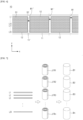
- FIG. 7 is a schematic diagram illustrating a battery assembling process after a pattern electrode is slit.
- a reference point marking apparatus 100 of the present invention is an apparatus for marking reference points on a pattern electrode 10 in which coated portions 12 and uncoated portions 11' are repeatedly arranged in a longitudinal direction.
- the pattern electrode 10 includes a plurality of reserved electrode lane parts to be slit into a plurality of electrode lanes in the longitudinal direction in a subsequent process.
- the reference point marking apparatus 100 includes a moving marking machine 20 for making reference points on the uncoated portion 11' of each of the reserved electrode lane parts arranged in a width direction Y of the pattern electrode 10 while moving in the width direction Y, and a controller 40 for controlling operations of the moving marking machine 20.
- the pattern electrode 10, which is a reference point marking target is an electrode in which the coated portions 12 and the uncoated portions 11' are repeatedly arranged as shown in FIG. 6 . That is, the pattern electrode 10 is an electrode coated with the coated portion 12 according to a predetermined number of patterns in the longitudinal direction X of the electrode.
- the coated portion 12 is coated with an electrode active material.
- an electrode current collector
- an electrode active material is intermittently discharged from a coater C to the current collector, thus forming the pattern electrode 10 in which the coated portions 12 and the uncoated portions 11' are repeatedly arranged.
- the coated portion 12 is dried as the coated electrode passes through an electrode oven D.
- the reference point marking apparatus 100 of the present invention may be disposed after the electrode oven D to mark a reference point M on the pattern electrode 10.
- the pattern electrode 10 includes a plurality of reserved electrode lane parts L1, ..., L20 to be slit into a plurality of electrode lanes in the longitudinal direction X in a subsequent process (a slitting process).
- the pattern electrode 10 of FIG. 6 includes a total of twenty reserved electrode lane parts L1 to L20. That is, a predetermined number of reserved electrode lane parts (twenty reserved electrode lane parts in the current embodiment) are arranged on the pattern electrode 10 in the width direction Y.
- the coated portion 12 and the uncoated portion 11' are repeatedly arranged on each of the reserved electrode lane parts, which are reference point marking targets, in the longitudinal direction of the electrode.
- the reference point M is marked on the uncoated portion 11' between the coated portions 12 of each of the reserved electrode lane parts.
- reference points are reference information for quality control and tracking in an electrode process, an assembly process, a subsequent winding process, and the like. Therefore, the form of the reference points on the each of the reserved electrode lane parts should be maintained without being damaged even when the subsequent slitting process is performed.
- the reference point need be marked in a range of upper and lower limits of each of the reserved electrode lane parts in the width direction (i.e., a boundary line S1 between adjacent reserved electrode lane parts). That is, it is preferable that the reference point be marked not to span the boundary line S1 between adjacent electrode lanes.
- the moving marking machine 20 of the present invention marks reference points on the uncoated portion 11' of each of the reserved electrode lane parts while moving in the width direction of the pattern electrode 10. Accordingly, it is possible to mark reference points on the uncoated portion 11' of each of the reserved electrode lane parts using one moving marking machine 20 without individually installing a marking machine along each of the reserved electrode lane parts.
- a plurality of reserved electrode lane parts may be divided into a predetermined number of groups of reserved electrode lane parts and reference points may be marked on each of the groups using one moving marking machine 20. In this case, the number of moving marking machines 20 may be installed to correspond to the number of groups.
- the moving marking machine 20 may mark reference points on the uncoated portions 11' of the reserved electrode lane parts while moving from one side to another side or from the other side to the side in the width direction.
- the moving marking machine 20 does not mark reference points on the uncoated portions 11 on an end or both ends of the pattern electrode 10 in the width direction, unlike in the related art. Instead, the reference points are marked on the uncoated portion 11' between the coated portions 12 of each of the reserved electrode lane parts.
- the reference points M remain and thus may be referred to when a roll map is generated or quality control is performed. Even when each of the reserved electrode lane parts is slit in the longitudinal direction, the reference points marked between the coated portions 12 of the reserved electrode lane parts remain and thus may be referred to when a roll map is generated in units of pattern numbers of the coated portions 12.
- the pattern electrode 10 which is a small electrode, can be managed or displayed in units of pattern numbers to create a roll map.
- the moving marking machine 20 may be, for example, an inkjet type ink marking machine, a laser type laser marking machine, or a punching type marking machine but is not limited thereto.
- An appropriate marking machine may be selected and used in a range in which the visibility of the reference points M is excellent and the uncoated portions 11' are not damaged. When a laser or punching type marking machine is used, the uncoated portions 11' may be damaged and thus care should be taken when the reference points M are marked.
- the moving marking machine 20 may be movably coupled to a guide shaft R installed on the pattern electrode 10 in the width direction.
- a moving mechanism of the moving marking machine 20 along the guide shaft R may be a well-known linear moving mechanism.
- the moving marking machine 20 may include a linear motor movable linearly along the guide shaft R.
- a part of the moving marking machine 20 guided when moving along the guide shaft R may be provided with a linear motor (LM) guide mechanism with a bearing to reduce friction.
- LM linear motor
- the moving marking machine 20 may further include a marking part 23.
- the marking part may be a nozzle part connected to an ink supply (not shown).
- the moving marking machine 20 may include a vision camera 21 or a detection sensor to detect and differentiate the coated portion 12 and the uncoated portion 11.
- the vision camera 21 may identify a boundary between the coated portion 12 and the uncoated portion 11' to allow the marking part 23 to perform marking on a predetermined marking position of the uncoated portion 11'.
- the detection sensor may be a detection sensor capable of identifying the position of the uncoated portion by comparing a color or brightness of a coated portion with that of an uncoated portion. For example, a color sensor or an optical sensor capable of identifying brightness may be used.
- the moving marking machine 20 may further include a lighting device 22 to allow the vision camera 21 or the recognition sensor to easily identify the uncoated portion 11' and the coated portion 12.
- Optical components such as a vision camera and a lighting device are expensive.
- the present invention is advantageous in that the number of expensive optical components can be significantly reduced because the reference point M can be marked on desired parts of a plurality of reserved electrode lanes using one moving marking machine 20 or a small number of moving marking machines 20.
- the moving marking machine 20 may determine a marking position using the vision camera or sensor and mark a reference point at the determined marking position using encoder information.
- the moving marking machine 20 moves in the width direction Y and thus a range of movement thereof need be set.
- a limit sensor (not shown) may be provided.
- the limit sensor and the controller 40 may be connected with each other, and the controller 40 may regulate the range of movement of the moving marking machine 20 according to a position detected by the limit sensor.
- the moving marking machine 20 may include a stopper (not shown) to prevent collision as needed.
- a mechanical and/or electronic stopper mechanism may be provided on the moving marking machine 20 or the guide shaft R coupled to the moving marking machine 20.
- the controller 40 controls the moving marking machine 20 to mark reference points M at predetermined positions and at predetermined intervals in the longitudinal direction of the pattern electrode 10. In particular, as shown in FIG. 4 , when the pattern electrode 10 is moved in the longitudinal direction X, the controller 40 may control the moving marking machine 20 to mark reference points.
- the controller 40 may control the speed of movement of the pattern electrode 10 in the longitudinal direction and determine the speed of movement of the moving marking machine 20 in connection with the speed of movement of the pattern electrode 10. That is, the controller 40 may control the moving marking machine 20 to mark a reference point at a desired marking position by taking into account the speed of movement of the pattern electrode 10, the speed of movement of the moving marking machine 20, positions at which reference points are marked, a marking interval, and the like.
- PLC programmable logic controller
- the reference point marking apparatus 100 of the present invention may further include a position measuring device 30 for obtaining data about a position of the pattern electrode 10 in the longitudinal direction as coordinate data to identify the position of the pattern electrode 10 in the longitudinal direction and the marking interval.
- the position measuring device 30 may obtain, as coordinate data, data about the position of the pattern electrode 10 in the longitudinal direction according to the amount of rotation of the unwinder UW or the rewinder RW.
- rotary encoders 30U and 30R that extract position values of the pattern electrode 10 from the amount of rotation of a motor driving the unwinder UW or the rewinder RW may be used as the position measuring device 30.
- FIG 4 illustrates that the rotary encoder 30U of the unwinder UW and the rotary encoder 30R of the rewinder RW are respectively disposed outside the unwinder UW and the rewinder RW but the encoders 30U and 30R may be respectively included in the unwinder UW and the rewinder RW.
- the position measuring device 30 may measure and specify the coordinates of the position of the pattern electrode 10 in the longitudinal direction in units of meters (m).
- the coordinates of the position are specified in units of meters and obtained in units of pattern numbers of the coated portion to be matched with the pattern electrode 10 for use in a small battery.
- the pattern electrode 10 may be defined as an electrode with a length corresponding to a total of 1200 pattern numbers.
- the length of one coated portion may be defined as one unit (coordinate).
- the reference points are marked on uncoated portions corresponding to 300 th , 600 th , and 900 th patterns for coated portions.
- the distance between reference points is 300 patterns as a pattern number.
- the length and width of a pattern of a coated portion may vary according to the type of the pattern electrode 10. However, even when the length of the pattern of the coated portion changes, the length of a pattern of an individual coated portion is the same and thus the position of the pattern electrode 10 in the longitudinal direction may be specified by taking into account the length of one pattern as a coordinate.
- a roll map may be created on the basis of units of pattern numbers, as will be described below.
- the position measuring device may count ⁇ 1' per rotation of the motor when the unwinder UW or the rewinder RW rotates by a length corresponding to one pattern number to express the position of the pattern electrode 10 in the longitudinal direction using coordinates of pattern number units.
- the controller 40 assigns a marking signal to the moving marking machine 20 on the basis of pattern number unit data when the pattern electrode 10 arrives at a position corresponding to predetermined pattern number.
- the marking signal is repeatedly generated at intervals of a set pattern number to control the moving marking machine 20 to mark reference points on the uncoated portion 11' of each of the reserved electrode lane parts in the longitudinal direction of the pattern electrode 10 at intervals of the pattern number.
- FIG. 6 illustrates an example in which when the pattern electrode 10 is moved in the longitudinal direction, the moving marking machine 20 marks reference point on uncoated portions 11' of a plurality of reserved electrode lane parts while moving in the width direction.
- the moving marking machine 20 moves, the pattern electrode 10 is also moved in the longitudinal direction and thus a path of marking by the moving marking machine 20 is a diagonal path inclined backward in the longitudinal direction due to the speed of movement of the pattern electrode 10 in the longitudinal direction.
- reference points are sequentially marked on the uncoated portions 11' of each of the reserved electrode lane parts at positions pushed backward by one pattern in the longitudinal direction, starting from a second electrode lane part.
- a distance (pattern number) by which the positions are pushed backward is not limited to one pattern. That is, the distance (pattern number) by which the positions are pushed backward may vary according to a total pattern number of the pattern electrode 10, the length of each pattern, the speed of movement of the pattern electrode 10, the speed of movement of the moving marking machine 20, etc. However, an interval (an interval of a pattern number) between reference points marked on the reserved electrode lane parts is the same.
- the moving marking machine 20 sequentially marks first reference points M1, M1', M1" ... on the reserved electrode lane parts while relatively moving backward by one pattern in the longitudinal direction from the first reserved electrode lane part L1 to the twentieth reserved electrode lane part L20, and thereafter moves upward in the width direction to return back to the uncoated portion 11' of the first reserved electrode lane part L1.
- the pattern electrode 10 is moved in a driving direction X and is spaced an interval of a predetermined pattern number (e.g., 300 patterns) from the first reference point M1 on the first reserved electrode lane part
- the moving marking machine 20 draws a diagonal marking path on each of the reserved electrode lane parts while moving downward in the width direction.
- the moving marking machine 20 marks second reference points M2, M2', M2" ... on reserved electrode lane parts while moving in the width direction. Thereafter, the moving marking machine 20 returns upward in the width direction, and repeatedly performs the above-described marking operation to mark third reference points M3, M3', M3", ... (see FIG. 13 ).
- the pattern electrode 10 of FIG. 4 is a double-sided electrode, the upper surface and lower surface of which are coated with an electrode active material. Accordingly, moving marking machines 20 and 20' may be respectively installed on the upper and lower surfaces of the pattern electrode 10.
- guide shafts R and R' serving as moving shafts of the moving marking machines 20 and 20' may also be installed on the upper and lower surfaces of the electrode, respectively.
- the present invention is also applicable to the pattern electrode 10 when the pattern electrode 10 is a single-sided electrode whose only one surface is coated with an active material.
- the moving marking machine 20 is installed on the one surface of the pattern electrode 10.
- FIG. 4 illustrates that the reference point marking apparatus 100 simultaneously marks reference points M on the upper and lower surfaces of the pattern electrode 10.
- reference points may be sequentially marked on an upper surface and lower surface of an electrode according to the layout of factory facility.
- the reference point marking apparatus 100 may mark reference points M on the upper surface of the pattern electrode 10, the pattern electrode 10 is consecutively moved while changing a driving path thereof, the lower surface of the pattern electrode 10 is coated with the active material and is dried, and thereafter, the reference point marking apparatus 100 may mark reference points M on the lower surface of the pattern electrode 10.
- the reference point marking apparatus 100 may be disposed on upper and lower surfaces of the electrode to mark reference points.
- reference points M may be marked on both the upper and lower surfaces of the electrode by one reference point marking apparatus 100.
- the marked reference points M may include sequence information of the reserved electrode lane parts and pattern number units or pattern sequence information thereof in the longitudinal direction of the pattern electrode 10. That is, the number of a reserved electrode lane part on which a reference point is marked in the width direction may be displayed on the reference point. In addition, the number of pattern numbers may be directly displayed or an order of pattern numbers may be displayed on the reference points to indicate a pattern number corresponding to a position of the uncoated portion 11' on which the reference point is marked.
- Such information may be displayed in the form of barcode or using a combination of numbers, Korean characters, English characters, and the like.
- A indicates sequence information of a reserved electrode lane part corresponding thereto.
- A represents a first reserved electrode lane part.
- the numbers after the alphabet represent pattern information.
- the pattern information includes a pattern number unit or pattern sequence information of the reference point in the longitudinal direction of the pattern electrode.
- the numbers after the alphabet is 0001 indicating a first pattern. If "G1372" is displayed on a reference point, G represents a seventh reserved electrode lane part and 1372 represents a 1372 th pattern in the longitudinal direction of the pattern electrode.
- the reversal of the front and rear ends of the pattern electrode 10 may be identified when the reference points M that are upside down are recognized. That is, in a series of electrode processes, including the coating process, the roll press process, and the slitting process, a rear end of an electrode roll in a preceding process may be a front end of the electrode roll in a subsequent process and thus front and rear ends of an electrode may be reversed and recognized when wound according to a winding direction.
- a corresponding process can be identified and the reference point M can be displayed on a roll map by reflecting the reversal of the reference point M or appropriately correcting the reference point M, when the alphabet is reversed and recognized.
- a pattern number or pattern sequence information of the reference point M and sequence information of a reserved electrode lane part can be identified at a glance.
- a relation between an order and a pattern number may be input to the controller 40 or a roll map generator, which will be described below.
- Information about reference point marking positions input to the controller 40 may be input to the roll map generator, and the roll map generator may generate roll maps of the pattern electrode 10 and each reserved electrode lane part on the basis of the reference point marking positions, as will be described below. As shown in FIG. 6 , even when the coordinates of a reference point displayed using a pattern number slightly change according to each reserved electrode lane part, the positions of marked patterns and a marking interval are input and thus a roll map may be easily generated or processed in a subsequent process using the reference points.
- reference points may be efficiently marked on the pattern electrode 10 with a plurality of reserved electrode lane parts in units of pattern numbers by one or more moving marking machines 20, thereby allowing the electrode process and quality control in each of processes to be automatically and efficiently performed.
- the pattern electrode 10 is slit into twenty electrode lanes in the longitudinal direction and the electrode lanes are slit in the width direction to form one electrode part for one pattern of a coated portion.
- Each electrode part is wound together with an electrode part of a different polarity and a separator to obtain a jelly roll type electrode assembly.
- Electrode assemblies J/R1, J/R2, J/R3, ..., J/Rn are accommodated in battery cans, an electrolyte is injected into the battery cans, and the battery cans are sealed to form small cylindrical batteries B1, B2, B3, ..., Bn.
- Reference points are marked on each electrode lane (reserved part) and one uncoated portion 11' for one pattern of each coated portion by the reference point marking apparatus 100 of the present invention, and used as reference points from the coating process to the winding process.
- reference points may remain in a corresponding electrode part even in some of the series of subsequent processes described above and thus be used as reference information when a corresponding process is performed or managed.
- FIG. 8 is a schematic view of a reference point marking apparatus of a second embodiment of the present invention.
- FIG. 9 is a schematic diagram illustrating a process of operating a moving marking machine according to the second embodiment.
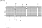
- FIG. 10 is a schematic diagram illustrating the marking of reference points and defects according to the second embodiment.
- a moving marking machine 20 may mark reference points on each reserved electrode lane part in the width direction and mark a defect on a pattern electrode 10 at the same time.
- the reference point marking apparatus 200 further includes a defect marking machine 50 disposed in parallel with the moving marking machine 20 in a width direction of the electrode.
- Uncoated portions 11 are provided in the longitudinal direction on one end or both ends of the pattern electrode 10 in the width direction. That is, a predetermined range of the pattern electrode 10 in the width direction is coated with an electrode active material to form coated portions 12, and remain parts of the pattern electrode 10 in the width direction are uncoated portions 11. Therefore, in the pattern electrode 10, an uncoated portion 11' is provided between coated portions 12 in the longitudinal direction of the pattern electrode 10 and uncoated portions 11 are provided on both ends of the pattern electrode 10 in the width direction. As described above, a reference point may be marked on the uncoated portion 11' and defect marking may be performed on the uncoated portion 11.
- defect marking machines are needed for both ends to perform marking on the uncoated portions 11 on both ends in the width direction.
- the reference point marking apparatus 200 for marking a defect on the uncoated portions 11 on both ends of the pattern electrode 10 in the width direction is illustrated.
- one guide shaft R is provided on the pattern electrode 10 in the width direction, and a total of three marking machines, i.e., the moving marking machine 20 and defect marking machines (a one-end marking machine 50A and an other-end marking machine 50B), are coupled to the guide shaft R.
- the moving marking machine 20 is installed to be movable along the guide shaft R.
- the one-end marking machine 50A and the other-end marking machine 50B may each include a marking part 53, a vision camera 51 (or a detection sensor), and a lighting device 52, similar to the moving marking machine 20.
- FIG. 10 illustrates defect marking G performed on an uncoated portion 11 on one end of the pattern electrode 10 by a marking part of a marking machine.
- reference points may be marked on the pattern electrode 10 in units of pattern numbers, and a defective point or defective section may be marked on the pattern electrode 10 when a defect is detected. Accordingly, because both reference points M and defects may be marked on the pattern electrode 10, the reference points M and the defects may be visually indicated on a roll map on the basis of the marks of the reference points and the defects.
- defect inspectors 60 and 70 may be placed before the position of the defect marking machine 50 to detect defects.
- the defect inspectors 60 and 70 may obtain inspection data about defects by inspecting the pattern electrode 10 moving in the roll-to-roll state, and obtain coordinate data of the pattern electrode 10 related to a defective point and/or a defective section at which the inspection data is obtained and pattern number unit data in connection with the position measuring device 30. At least one of the defect inspectors 60 and 70 is disposed before the position of the defect marking machine 50.
- the defect marking machine 50 may mark a defective point and/or a defective section (defect marking G) on an uncoated portion 11 on one end of the pattern electrode 10 or uncoated portions 11 on both ends thereof in the width direction, based on the coordinate data and the pattern number unit data received from the defect inspectors 60 and 70. That is, when a defect is detected at a portion of the pattern electrode 10 corresponding to a 450 th pattern number by the defect inspector, the defect inspector marks a defect on an uncoated portion 11 on one end of the electrode corresponding to the pattern number or uncoated portions 11 on both ends thereof.
- defect marking G may be performed at a position or section corresponding to the coordinates of the portion on the basis of the coordinate data.
- Examples of the defect inspectors 60 and 70 may include an electrode slurry loading rate measuring device, a dimension and width measuring device, an appearance inspector, and the like installed on a transfer line of the pattern electrode 10.
- a non-contact type thickness measuring sensor such as an ultrasonic sensor, a displacement sensor, a laser sensor, and a confocal thickness sensor may be employed.
- the confocal thickness sensor is capable of measuring a slurry loading rate by analyzing the wavelength of reflected light of light emitted from the sensor and calculating the distance (thickness) between the sensor and an electrode.
- a type of vision measuring device capable of photographing or scanning the appearance of an electrode to be coated to measure the width of the electrode, the widths of a coated portion and an uncoated portion, etc. may be employed as the dimensional and width measuring device.
- the widths of the coated portion and the uncoated portion are identified, whether there is a mismatch between the coated portion and the uncoated portion may be also identified.
- the appearance inspector may obtain an image of the appearance of an electrode by imaging the appearance of the electrode. From the obtained image, data about appearance defects such as pinholes, lines, and a crater shape may be obtained, and data about on insulation appearance or insulation defects may also be obtained.
- Examples of the appearance inspector may include a sensor capable of identifying the color of an electrode, e.g., an inspector with a color sensor. A part, e.g., a connection tape or a PET film, of a different color from that of the electrode may be detected using the color sensor.
- a defect inspector for detecting other types of defects may also be applied.
- the defect inspectors 60 and 70 may be connected to and with the position measuring device 30 or the controller 40 connected to the position measuring device 30 to obtain location data (coordinates and pattern number unit data) of a defective point at which a defect is detected or a defective section in which the defect occurs continuously in the longitudinal direction. Therefore, the defect inspectors 60 and 70 may not only obtain inspection data about the type, size, shape, properties, etc. of the defect but also obtain coordinate data and pattern number unit data of the position of the electrode at which the inspection data is obtained.
- the inspection data, the coordinate data, and the pattern number unit data are transmitted to the controller 40.
- the controller 40 instructs the defect marking machine 50 to mark a defective point and/or a defective section on the basis of the above data.
- the defect marking machine 50 marks the defective point and/or the defective section (defect marking G) on the basis of the coordinate data and the pattern number unit data.
- the defect inspectors 60 and 70 detect a defect at a predetermined position (coordinates) on the pattern electrode 10 in the longitudinal direction, and the controller 40 controls the defect marking machine 50 to mark the defect at the position (coordinates).
- the controller 40 may calculate a point in time when a part of the pattern electrode 10 corresponding to the defective point and/or the defective section will reach the defect marking machine 50, based on the distances between the defect inspectors 60 and 70 and the defect marking machine 50 and the speed of movement of the pattern electrode 10.
- the defect marking machine 50 marks the defective point and/or the defective section (defect marking G) according to a marking instruction from the controller 40.
- the position (coordinates) of the defective point and/or the position (coordinates) of the defective section may be specified on the basis of coordinate data and pattern number unit data received from a defect inspector.
- the controller 40 controls the defect marking machine 50 to mark a defect at a specific point in time on the basis of the specified position (coordinates).
- the controller 40 may obtain coordinate data of a defective point or a defective section in connection with the defect inspector and a position measuring device, and instruct the defect marking machine to mark a defect on the basis of the coordinate data.
- FIG. 11 is a schematic view of a roll map generation apparatus according to another aspect of the present invention.
- FIG. 12 is a schematic view of a data visualizing device included in a roll map generator.
- FIG. 13 is a schematic view of a roll map of a pattern electrode and a roll map of each reserved electrode lane part generated by a roll map generation apparatus of the present invention.
- a roll map generation apparatus 300 of the present invention includes: a position measuring device 30 configured to obtain, as coordinate data, data about a position of a pattern electrode 10, in which coated portions 12 and uncoated portions 11' are repeatedly arranged in a longitudinal direction of the pattern electrode 10, in the longitudinal direction according to the amount of rotation of an unwinder UW or a rewinder RW when the pattern electrode 10 is moved in the roll-to-roll state between the unwinder UW and the rewinder RW, and represent the coordinate data in the form of pattern number unit data of the coated portions 12; a marking machine 20 configured to mark reference points M on the pattern electrode 10 in the longitudinal direction of the pattern electrode 10 at predetermined intervals in connection with the position measuring device 30; and a roll map generator 80 configured to obtain the coordinate data of the position of the pattern electrode 10 in the longitudinal direction, the pattern number unit data of the coated portions 12, and pattern number unit data of the reference points M in connection with the position measuring device 30 and the marking machine 20, and generates a roll map by displaying at least the pattern number unit data
- the pattern electrode 10 includes a plurality of reserved electrode lane parts to be slit into a plurality of electrode lanes in the longitudinal direction of the pattern electrode 10 in a subsequent process.
- the marking machine 20 is a moving marking machine 20 which marks reference points on uncoated portions 11' of the reserved electrode lane parts arranged in a width direction of the pattern electrode 10 while moving in the width direction.
- the coordinates of the position of the pattern electrode 10 in the longitudinal direction may be specified according to the amount of rotation of the unwinder UW or the rewinder RW.
- the position measuring device 30 may represent the coordinates of the position of the electrode 10 in the longitudinal direction using the pattern number unit data of the coated portions. For example, a pattern number unit '0' obtained by the position measuring device 30 represents a front end of the pattern electrode 10, and when coordinates corresponding to a 1200 th pattern number are obtained from the pattern electrode 10 with 1200 pattern numbers, it should be understood that a rear end of the pattern electrode 10 is measured by the position measuring device.
- the pattern number unit data of the pattern electrode 10 in the longitudinal direction may be detected by the rotary encoder 30U installed in the unwinder UW or a rotary encoder 30R installed in the rewinder RW.
- the moving marking machine 20 employed in the reference point marking apparatuses 100 and 200 described above may be applied as the marking machine.
- a defect marking machine 50 that marks a defect on an uncoated portion 11 on one end of the pattern electrode 10 or another end thereof in the width direction may further be provided. As shown in FIG. 11 , the defect marking machine 50 may be arranged in parallel with the moving marking machine 20 in the width direction of the electrode.
- reference points M may be marked at predetermined intervals in the longitudinal direction of the pattern electrode 10 and defects may be marked on the uncoated portions 11.
- the present invention includes the roll map generator 80 that obtains, as coordinate data, data about the position of the pattern electrode 10 in the longitudinal direction and pattern number unit data of the reference points M in connection with the marking machines 20 and 50, and generates a roll map by displaying the coordinate data and the pattern number unit data on the roll map.
- the roll map generator 80 may obtain pattern number unit data in the longitudinal direction of the pattern electrode 10 in connection with the position measuring device, and represent the positions of the reference points M and intervals therebetween in the form of pattern number unit data in connection with the moving marking machine 20.
- the pattern number unit data of the reference points M may be transmitted to the roll map generator 80 directly from the moving marking machine 20 or through the controller 40.
- the roll map generator 80 may generate a roll map of the pattern electrode 10 and a roll map of each of the reserved electrode lane parts of the pattern electrode 10, based on the pattern number unit data of the reference points M marked by the moving marking machine 20.
- the roll map generator 80 may generate a roll map that displays not only information about the reference points M but also information about defects.
- at least one of defect inspectors 60 and 70 that inspect the pattern electrode 10 to obtain inspection data about defects and obtain coordinate data and pattern number unit data about a defective point and/or a defective section at which the inspection data is obtained in connection with the position measuring device may be provided before the position of the defect marking machine 50.
- the types of the defect inspectors 60 and 70 have been described above and thus an additional description thereof will be omitted here.
- the defect marking machine 50 may perform defect marking on a defect on an uncoated portion on one end of the pattern electrode 10 or uncoated portions 11 on both ends thereof in the width direction, based on the coordinate data and the pattern number unit data received from the defect inspectors 60 and 70.
- the roll map generator 80 may display coordinate data of the defect marking G, the pattern number unit data, and pattern number unit data of the reference points M on the roll map.
- the roll map generator 80 may include a database 81 storing data obtained from the defect inspectors 60 and 70, the moving marking machine 20, the defect marking machine 50, and the position measuring device 30 or storing data about the quality, dimensions, etc. of normal electrodes.
- the roll map generator 80 may further include a central processing unit (CPU) 82 that processes obtained data and instructs a visualizing device 83 included in the roll map generator 80 to visualize the processed data.
- CPU central processing unit
- the roll map generator 80 includes the visualizing device 83 for defining a visualization area on which a roll map that simulates the pattern electrode 10 is to be formed and displaying pattern number unit data on the defined visualization area.
- the visualizing device 83 may be connected to the CPU 82 and visualize and display inspection data and pattern number unit data according to an instruction from the CPU 82.
- the visualizing device 83 includes an obtained data inputter 83a, a coordinates (pattern number)-on-roll map identification part 83b, and an image generator 83c.
- the obtained data inputter 83a receives data from the CPU 82.
- the coordinates-on-roll map identification part 83b may define a visualization area on which a roll map is to be formed and define coordinates of pixels in the visualization area for each data element of obtained source data.
- the coordinates-on-roll map identification part 83b may calculate and determine the visualization area of the roll map from data about the size of the pattern electrode 10 according to a predetermined scale transformation scale.
- the visualization area of the roll map may be calculated and determined from location data of the pattern electrode 10 in the longitudinal direction and the width direction according to a predetermined scale transformation scale.
- the coordinates-on-roll map identification part 83b may map obtained data about quality or defects and location data of the electrode 10 (in the width direction and the length direction), and allocate the mapped data on the visualization area (the roll map) according to the coordinates of the pixels.
- the image generator 83c may express elements of the mapped data allocated to the coordinates of the pixels in the visualization area using at least one legend.
- the legend refers to various shapes such as circles, quadrangles, and triangles displayed in the visualization area or the shapes to which colors are assigned. Therefore, the image generator 83c visually displays various types of data related to quality or defects at the coordinates of pixels corresponding to pieces of location data of the actual pattern electrode 10 on the visualization area of the roll map using shapes, forms, and colors designated for various types of data, thereby generating a roll map of the present invention.
- data corresponding to a specific range of the roll map may be retrieved from the storage and displayed on a screen (image generation) in association with the specific range.
- the CPU 82 may instruct the visualizing device 83 to visualize and display inspection data identified as abnormal in comparison with normal data stored in the database 81 to be distinguished from other data.
- the setting of the size of the visualization area or the generation of an image by identifying the coordinates of the visualization area may be performed by various types of general user interfaces or various programs or processing tools related to data allocation, processing, analysis and visualization. Accordingly, the roll map generator 80 described above is only an example and thus is not limited by the above-described embodiments.
- the roll map generator 80 may be, for example, a data processing system such as a manufacturing execution system (MES).
- MES manufacturing execution system
- a manufacturing process of the pattern electrode 10 employs an electrode MES for managing a series of electrode manufacturing processes such as coating, pressing, and slitting. Accordingly, when the coordinate data, the inspection data, and the like are transmitted to the electrode MES, the roll map described above may be generated by the electrode MES.
- the roll map generation apparatus 300 of the present invention may display the generated roll map on a display 90 so that the reference points M and data about defects may be easily visually grasped at a glance.
- the roll map generation apparatus 300 of the present invention may include a controller (PLC) that controls the movement of an electrode between the unwinder UW and the rewinder RW.
- the controller may be connected to the position measuring device 30 and the defect inspectors 60 and 70 to transmit pattern number unit data of the position of the electrode and the inspection data to the roll map generator 80.
- the controller 40 may process the inspection data and the pattern number unit data to be easily processed by the roll map generator 80.
- controller (PLC) 40 is connected to the defect inspectors 60 and 70, the encoder or the like to control the roll-to-roll transfer of an electrode, it is more efficient to transmit data through the controller 40 in terms of data processing and management rather than directly transmit data from the defect inspectors 60 and 70, the encoder or the like to a data processing system such as the electrode MES.
- FIG. 13 illustrates a roll map of a pattern electrode 10 generated by a roll map generation apparatus of the present invention.
- FIG. 13 illustrates roll maps of a first reserved electrode lane part, a second reserved electrode lane part, and a twentieth reserved electrode lane part. Roll maps of a third reserved electrode lane part to a nineteenth reserved electrode lane part are omitted for convenience of illustration.
- the positions of the reference points M are pushed backward in the longitudinal direction as the numbers of reserved electrode lane parts increase in the width direction.
- Defective points or defective sections G are also displayed on the roll map by a defect inspector.
- the defect inspector transmits inspection data and pattern number unit data of a position at which the inspection data is obtained to the roll map generator 80 in connection with the position measuring device, and the roll map generator 80 visualizes and displays a defective point and/or a defective section at a position of a corresponding patter number on the roll map on the basis of the inspection data and the pattern number unit data.
- the roll map generator 80 of the present invention may display reference points M and pattern number unit data of defective points and/or defective sections on the roll maps.
- the roll map generator 80 may also display coordinate data (meter (m) information) in the longitudinal direction of the pattern electrode 10 on the roll map, in addition to the pattern number unit data. That is, according to the present invention, not only coordinate information but also pattern information may be used and displayed when the roll map is generated and thus are suitable for use in a pattern electrode process for small batteries.
- reference points can be marked on a pattern electrode using a simple configuration, thereby greatly simplifying a marking process and reducing costs.
- the present invention is very suitable for a management mechanism of small pattern electrodes in which electrodes are managed in units of pattern numbers because reference points are marked on the uncoated portions 11' of the reserved electrode lane parts on the basis of the pattern number unit data. Because both reference points and defects can be marked, electrode defects can be easily detected.
- a roll map can be generated using the reference point marking apparatus, it is very convenient to automatically perform quality control of electrodes.
- quality control history can be managed on the basis of the roll map, quality tracking can be easily performed when product abnormality occurs.
Landscapes
- Engineering & Computer Science (AREA)
- Chemical & Material Sciences (AREA)
- Manufacturing & Machinery (AREA)
- General Chemical & Material Sciences (AREA)
- Electrochemistry (AREA)
- Chemical Kinetics & Catalysis (AREA)
- Physics & Mathematics (AREA)
- Mechanical Engineering (AREA)
- Health & Medical Sciences (AREA)
- General Physics & Mathematics (AREA)
- Immunology (AREA)
- Pathology (AREA)
- General Health & Medical Sciences (AREA)
- Analytical Chemistry (AREA)
- Biochemistry (AREA)
- Life Sciences & Earth Sciences (AREA)
- Optics & Photonics (AREA)
- Plasma & Fusion (AREA)
- Signal Processing (AREA)
- Computer Vision & Pattern Recognition (AREA)
- Textile Engineering (AREA)
- Materials Engineering (AREA)
- Battery Electrode And Active Subsutance (AREA)
- Coating Apparatus (AREA)
Abstract
Description
- The present invention relates to a reference point marking apparatus for efficiently marking reference points on a pattern electrode in which coated portions and uncoated portions are repeatedly arranged in a longitudinal direction.
- The present invention also relates to a roll map generation apparatus using the reference point marking apparatus.
- This application claims the benefit of priority based on
Korean Patent Application No. 1 0-2022-0108292, filed on August 29, 2022 - With the development of technologies for mobile devices and an increase of the demand for mobile devices, the demand for secondary batteries is sharply increasing. Among secondary batteries, lithium secondary batteries have been widely used as energy sources of various types of electronic products as well as various types of mobile devices in terms of high energy density, a high operating voltage, and excellent preservation and lifespan characteristics thereof.
- A so-called electrode process of manufacturing electrodes of a lithium secondary battery includes a coating process of forming a positive electrode and a negative electrode by applying an active material and an insulating material to a surface of a metal electrode plate, which is a current collector, a roll press process of rolling the coated electrodes, and a slitting process of cutting the rolled electrodes according to sizes.
- In the electrodes manufactured by the electrode process, electrode tabs are formed by a notching process, a separator is interposed between the positive electrode and the negative electrode to form an electrode assembly, and thereafter, the electrode assembly is stacked, folded, or wound to be packaged into a pouch or a can, and an electrolyte is injected by an assembly process, thereby achieving a form of secondary battery. Thereafter, the assembled secondary battery is charged or discharged and an activation process is performed to give battery characteristics, thereby achieving a secondary battery as a final finished product.
- When a fracture or defect occurs in an electrode in the electrode process, a fractured or defective portion may be removed and discontinuous portions of the electrode may be connected by a connection tape. To maintain the quality of the electrode, a front or rear end portion of the electrode that is not uniform in quality may be removed. In this case, a worker may arbitrarily input the length of a cut portion (electrode loss rate) of the electrode to a controller or the like after the front or rear end portion of the electrode is removed and discontinuous portions of the electrode are connected. However, because the electrode loss rate is manually measured and input by the worker, an actual consumed electrode loss rate cannot be accurately identified. In addition, an input electrode loss rate may vary according to a worker.
- In this case, the fracture of the electrode and the connection of the discontinuous portions of the electrode may be identified by detecting the connection tape in a subsequent process but the electrode loss rate is input by the worker and thus an accurate electrode loss rate is difficult to identify. When a loss rate of a cut part of the electrode is not accurate, the coordinates of a position of the electrode may change in a subsequent process, thus preventing the subsequent process from being performed at a desired position. When changes in quality in sub-processes of the electrode process are compared and analyzed, a criterion may vary according to an electrode loss rate, thus preventing a quality comparison from being reliably performed according to the position of an electrode.
- Recently, a roll map has been used to simulate an electrode that is in a roll-to-roll state and display data about quality or a defect on a roll map bar displayed on a screen. Because such a roll map is individually created in sub-processes of the electrode process, such as a coating process, a roll press process, and a slitting process, information about the roll map is downloaded to check information about a defect in quality or a fracture of an electrode in a preceding process and check the data and remove the defect or perform a necessary follow-up process in a subsequent process. However, when an electrode loss rate is not accurately identified as described above, location data of the electrode displayed on the roll map may change, thus preventing data about quality or a position of a defect from being accurately displayed, and there is a risk of performing the subsequent process on the basis of the coordinates of a wrong position when the roll map is referred to in the subsequent process.
-
FIG. 1 is a schematic diagram illustrating distortion of the coordinates of an electrode in a longitudinal direction according to whether there are reference points, when a loss occurs in the electrode. - An upper drawing of
FIG. 1 illustrates a roll map RM that simulates a movement of an electrode in the roll-to-roll state between an unwinder UW and a rewinder RW. For convenience of description,FIG. 1 illustrates only a fracture of an electrode and a connection tape T although a large amount of data about details of quality and defects is visually displayed on the actual roll map RM. - The roll map RM on the upper drawing of
FIG. 1 simulates an actual electrode and various types of fractures occur in the actual electrode. A 50 m fracture and a 60 m fracture occurring when one (current process) of the sub-processes of the electrode process was performed are displayed on a roll map (RM). In addition, the removal of a front end portion of the electrode by 30 meters in a process before entering the corresponding process and the removal of a rear end portion thereof by 35 meters in the corresponding process are displayed. - In this case, when the fractures or the removed front and rear end portions of the electrode (electrode loss portions) are considered, only the connection tape T connecting the fractures remains as shown in a middle drawing of
FIG. 1 . That is, the middle drawing ofFIG. 1 illustrates a form of the actual electrode. In the middle drawing, for example, the position of the connection tape T may be detected, for example, by a seam detection sensor. However, because the fractures or the removed portions of the electrode do not actually remain on the electrode and thus an electrode loss rate corresponding to the length of the removed portions (loss portions) of the electrode cannot be identified. As described above, data about the removed portions of the electrode is manually input by a worker and thus it is difficult to identify an accurate electrode loss rate. - When the electrode loss rate cannot be identified, the roll map RM of the electrode process may be as shown in the middle drawing of
FIG. 1 , thus resulting in distortion of the coordinates of positions on the roll map. In the upper drawing ofFIG. 1 , for convenience of description, the connection tape T is also illustrated on an assumption that the lengths of the fractures/removed portions of the electrode are known, and the form shown in the middle drawing ofFIG. 1 is achieved when an actual electrode loss occurs. - A lower drawing of
FIG. 1 shows that the distortion of the coordinates on the roll map RM is prevented using reference points. - In the roll map RM in the lower drawing of
FIG. 1 , electrode loss parts are displayed using reference points M1, M2, and M3 at predetermined intervals. The number of the reference points M1, M2, and M3 and the intervals may vary according to the length or specifications of the electrode. InFIG. 1 , it is assumed that the length of an electrode is 1200 m, and the reference points M1, M2, and M3 are marked at points of 300 m, 600 m, and 900 m, respectively. When the reference points M1, M2, and M3 are actually marked on an actual electrode and measured when an electrode loss occurs, intervals among the reference points M1, M2, and M3 change and thus an electrode loss rate may be easily identified on the basis of a rate of change. When the electrode loss rate is identified as described above, the reference points M1, M2, and M3 and an electrode loss length may be displayed together as shown in the roll map RM in the lower drawing ofFIG. 1 . Accordingly, the dimensions (absolute coordinates) of the electrode in the longitudinal direction in which the electrode loss length is reflected and the dimensions (relative coordinates) of the electrode in the longitudinal direction in which the electrode loss length is not reflected may be displayed together on one roll map. - As described above, when reference points are employed for an electrode, an electrode loss rate may be identified by comparing the positions of the reference points before a change of an interval between the reference points with the measured positions of the reference points and be reflected on a roll map.
- In addition, the reference points serve as references for identifying and specifying an individual battery together with cell identification (ID) given to each electrode in an electrode coating process, a roll press and slitting process, an assembly process such as notching, a process of winding and transferring an electrode, a battery can insertion process, etc. Therefore, when a problem such as a defect occurs in a specific process, quality control can be easily performed by analyzing or tracking a cause on the basis of the cell ID and the reference points.
-
FIG. 2 is a schematic diagram illustrating marking reference points on an electrode with a single electrode lane. - In the drawing, an arrow indicates a driving direction of an
electrode 1. In theelectrode 1,uncoated portions 1a are formed on both ends of a coatedportion 1b. Therefore, it was sufficient to mark reference points M on the uncoated portion(s) 1a on an end or both ends of theelectrode 1 using a referencepoint marking machine 2 of the related art. - However, such conventional marking devices are not suitable to mark reference points on a so-called pattern electrode.
-
FIG. 3 illustrates an example of apattern electrode 10. - The
pattern electrode 10 is an electrode in which coatedportions 12 and uncoated portions 11' are repeatedly arranged in the longitudinal direction to form a pattern. - In a subsequent process, the
pattern electrode 10 is slit in the width direction with respect to the non-coated portion 11' between the coatedportions 12. One coatedportion 12 slit from thepattern electrode 10 may be stacked with a coated portion of an electrode of different polarity and a separator to form a stack cell type electrode assembly or be wound with the coated portion and a separator of the electrode of the different polarity to form a jelly roll type electrode assembly. - In particular, in the case of a pattern electrode for use in a small-sized battery, first, a plurality of electrode lanes are formed by slitting the pattern electrode in the longitudinal direction before slitting the uncoated portion 11' in the width direction. Then, the uncoated portion 11' between coated portions of each of the electrode lanes is cut. In this case, an electrode assembly may be formed by stacking or winding the coated portions of each of the electrode lanes.
- When a marking apparatus of
FIG. 2 is applied to a pattern electrode as shown inFIG. 3 , the following problems may occur. - First, after the manufacture of the pattern electrode, uncoated portions (knurling portions) 11 at both ends of the pattern electrode in the width direction are removed in a slitting process. However, as shown in
FIG. 2 , in the related art, reference points are marked on theuncoated portions 11 at both ends of the pattern electrode in the width direction and thus are removed after the slitting process. Thus, a gray zone in which quality control cannot be performed on the basis of the reference points is generated between the slitting process and a winding process. - Second, in the case of a large electrode, reference points are marked in unit of lengths (e.g., meters (m)), and a roll map is created or corrected by adding coordinates in units of length when an interval between the reference points changes due to a defect. However, a small electrode such as a pattern electrode is small in size and thus is managed in units of pattern numbers of coated portions, together with the coordinates of such length units. That is, as the coordinates of the electrode in the longitudinal direction, coordinates may be assigned in units of pattern numbers, together with meter information, and a specific position in the longitudinal direction may be also displayed using a pattern number. A roll map of the pattern electrode may also be expressed in units of pattern numbers. Therefore, it is necessary to change a reference point marking mechanism of a large electrode to be suitable to mark reference points on a small electrode.
- Third, when a pattern electrode is slit into a plurality of electrode lanes, a plurality of marking machines are required to mark reference points on each of the electrode lanes. However, when the number of marking machines increases, manufacturing costs increase and an installation process is complicated. The number of optical components required for each marking machine increases, thus greatly increasing manufacturing costs. In addition, a space, for accommodation of a plurality of marking machines, between reserved electrode lane parts of a small pattern electrode is insufficient.
- Therefore, there is a need to develop a technique for efficiently marking reference points on a pattern electrode.
-
Korean Registered Patent Publication No. 10-601567 - The present invention is directed to providing a reference point marking apparatus for efficiently marking reference points on a pattern electrode in which coated portions and uncoated portions are repeatedly arranged in a longitudinal direction.
- The present invention is also directed to providing a roll map generation apparatus for effectively displaying information about reference points and information about defects on a roll map by using the reference point marking apparatus.
- An aspect of the present invention provides a reference point marking apparatus for marking reference points on a pattern electrode in which coated portions and uncoated portions are repeatedly arranged in a longitudinal direction, in which the pattern electrode includes a plurality of reserved electrode lane parts to be slit into a plurality of electrode lanes in the longitudinal direction in a subsequent process, and the reference point marking apparatus includes a moving marking machine configured to mark reference points on uncoated portions of the reserved electrode lane parts arranged in a width direction of the pattern electrode while moving in the width direction, and a controller configured to control an operation of the moving marking machine.
- The uncoated portions of the reserved electrode lane parts may include portions to be slit in the width direction in a subsequent process, and the reference points may be marked on regions of the uncoated portions instead of the portions to be slit in the width direction.
- The moving marking machine may mark reference points when the pattern electrode is moved in the longitudinal direction.
- In this case, when the moving marking machine marks reference points on the uncoated portions of the plurality of reserved electrode lane parts while moving in the width direction, a marking path may be a diagonal path inclined backward in the longitudinal direction due to the speed of movement of the pattern electrode in the longitudinal direction.
- More specifically, the moving marking machine may sequentially mark reference points on the uncoated portions of each of reserved electrode lane parts at positions pushed backward by one pattern in the longitudinal direction.
- The moving marking machine may mark reference points on the uncoated portions of the plurality of uncoated portions at intervals of predetermined pattern numbers of the coated portions in the longitudinal direction.
- The pattern electrode may be a double-sided electrode, the upper surface and the lower surface of which are coated with an electrode active material, and the moving marking machine may be installed on the upper surface and the lower surface of the pattern electrode.
- The reference point marking apparatus may further include a position measuring device configured to obtain, as coordinate data, data about a position of the pattern electrode in the longitudinal direction according to an amount of rotation of an unwinder or a rewinder and represent the coordinate data in the form of pattern number unit data of the coated portions, when the pattern electrode is moved in the roll-to-roll state between the unwinder and the rewinder in the longitudinal direction, and the controller may control the moving marking machine to mark reference points on the uncoated portions of the plurality of reserved electrode lane parts at intervals of the pattern numbers of the coated portions, based on the pattern number unit data.
- The marked reference points may include sequence information of the reserved electrode lane parts and pattern number units or pattern sequence information of the reference points in the longitudinal direction of the pattern electrode.
- The reference point marking apparatus may further include a defect marking machine that marks a defect on an uncoated portion on one end of the pattern electrode or uncoated portions on both ends thereof in the width direction and is disposed in parallel with the moving marking machine in the width direction of the pattern electrode.
- In this case, a guide shaft may be disposed on the pattern electrode in the width direction.
- The moving marking machine and the defect marking machine may be coupled to the guide shaft.
- The moving marking machine may be installed to be movable along the guide shaft.
- At least one defect inspector configured to inspect the pattern electrode to obtain inspection data of a defect and obtain coordinate data of the pattern electrode related to a defective point and/or a defective section at which the inspection data is obtained and pattern number unit data in connection with the position measuring device may be provided before a position of the defect marking machine, and the defect marking machine may mark a defect on the uncoated portion(s) on the one end or the both ends of the pattern electrode in the width direction on the basis of the coordinate data and the pattern number unit data received from the at least one defect inspector.
- The controller may calculate a point in time when the defective point and/or the defective section will reach the at least one defect inspector, based on a distance between the at least one defect inspector and the defect marking machine and the speed of movement of the pattern electrode, and control the defect marking machine to mark a defect on the defective point and/or the defective section at the point in time.
- Another aspect of the present invention provides a roll map generation apparatus including a position measuring device configured to obtain, as coordinate data, data about a position of a pattern electrode in a longitudinal direction of the pattern electrode according to an amount of rotation of an unwinder or a rewinder when the pattern electrode is moved in the roll-to-roll state between the unwinder and the rewinder, and represent the coordinate data in the form of pattern number unit data of coated portions, wherein coated portions and uncoated portions are repeatedly arranged on the pattern electrode;
- a marking machine configured to mark reference points on the pattern electrode at predetermined intervals in the longitudinal direction of the pattern electrode in connection with the position measuring device; and
- a roll map generator configured to obtain the coordinate data related to the position of the pattern electrode in the longitudinal direction, the pattern number unit data of the coated portions, and pattern number unit data of the reference points in connection with the position measuring device and the marking machine, and generate a roll map, which simulates an electrode moving in the roll-to-roll state, by displaying at least the pattern number unit data on the roll map.
- The pattern electrode includes a plurality of reserved electrode lane parts to be slit into a plurality of electrode lanes in the longitudinal direction of the pattern electrode in a subsequent process.
- The marking machine is a moving marking machine configured to mark reference points on uncoated portions of the reserved electrode lane parts arranged in a width direction of the pattern electrode while moving in the width direction.
- The roll map generator generates a roll map of the pattern electrode and a roll map of each of the reserved electrode lane parts on the basis of the pattern number unit data marked by the moving marking machine.
- The roll map generation apparatus may further include a defect marking machine that marks a defect on an uncoated portion on one end of the pattern electrode or both ends thereof in the width direction and is disposed in parallel with the moving marking machine in the width direction of the pattern electrode.
- At least one defect inspector configured to inspect the pattern electrode to obtain inspection data of a defect and obtain coordinate data of the pattern electrode related to a defective point and/or a defective section at which the inspection data is obtained and pattern number unit data in connection with the position measuring device may be provided before a position of the defect marking machine.
- The defect marking machine may mark a defect on the uncoated portion(s) on the one end or the both ends of the pattern electrode in the width direction on the basis of the coordinate data and the pattern number unit data received from the defect inspector.
- The roll map generator may mark both the reference point and defects on a roll map on the basis of the coordinate data and the pattern number unit data.
- According to the present invention, reference points can be marked to correspond to all a plurality of reserved electrode lane parts using a moving marking machine moving in a width direction of a pattern electrode.
- Therefore, the number of marking machines required to mark reference points can be greatly reduced, thus greatly reducing manufacturing costs.
- According to the present invention, a roll map that simulates a pattern electrode and each reserved electrode lane part can be implemented using the reference point marking apparatus on the basis of pattern number unit data of reference points. Both information about reference points and information about electrode defects can be displayed on the roll map. Therefore, data related to poor quality of the pattern electrode can be easily visually identified at a glance in relation to the reference points.
- In addition, the roll map on which the reference points are displayed can be referred to in sub-processes of an electrode process, thus facilitating performing processing, defect removal, quality tracking and management, and the like in the subsequent processes.
-
-
FIG. 1 is a schematic diagram illustrating distortion of the coordinates of an electrode in a longitudinal direction according to whether there are reference points, when a loss occurs in the electrode. -
FIG. 2 is a schematic diagram illustrating marking reference points on an electrode with a single electrode lane. -
FIG. 3 is a schematic view of an example of a pattern electrode. -
FIG. 4 is a schematic view of a reference point marking apparatus of a first embodiment of the present invention. -
FIG. 5 is a schematic diagram illustrating a process of operating a moving marking machine according to the first embodiment. -
FIG. 6 is a schematic diagram illustrating marking reference points according to the first embodiment. -
FIG. 7 is a schematic diagram illustrating a battery assembling process after a pattern electrode is slit. -
FIG. 8 is a schematic view of a reference point marking apparatus of a second embodiment of the present invention. -
FIG. 9 is a schematic diagram illustrating a process of operating a moving marking machine according to the second embodiment. -
FIG. 10 is a schematic diagram illustrating the marking of reference points and defects according to the second embodiment. -
FIG. 11 is a schematic view of a roll map generation apparatus according to another aspect of the present invention. -
FIG. 12 is a schematic view of a data visualizing device included in a roll map generator. -
FIG. 13 is a schematic view of a roll map of a pattern electrode generated by a roll map generation apparatus of the present invention. - Hereinafter, a configuration of the present invention will be described in detail with reference to the accompanying drawings and various embodiments. Embodiments described below are provided as examples to help the understanding of the present invention, the accompanying drawings are not drawn on actual scale to help the understanding of the present invention, and the sizes of some components may be exaggerated.
- The present invention may be embodied in many different forms and implemented in various embodiments. Thus, certain embodiments are illustrated in the drawings and described in detail herein. It should be, however, understood that the present invention is not limited to particular embodiments and include all modifications, equivalents, and alternatives falling within the idea and scope of the present invention.
- A reference point marking apparatus according to an embodiment of the present invention is an apparatus for marking reference points on a pattern electrode in which coated portions and uncoated portions are repeatedly arranged in a longitudinal direction, in which the pattern electrode includes a plurality of reserved electrode lane parts to be slit into a plurality of electrode lanes in the longitudinal direction in a subsequent process, and the reference point marking apparatus includes a moving marking machine configured to mark reference points on uncoated portions of the reserved electrode lane parts arranged in a width direction of the pattern electrode while moving in the width direction, and a controller configured to control an operation of the moving marking machine.
- A roll map generation apparatus of another aspect of the present invention includes a position measuring device configured to obtain, as coordinate data, data about a position of a pattern electrode in a longitudinal direction of the pattern electrode according to an amount of rotation of an unwinder or a rewinder when the pattern electrode is moved in the roll-to-roll state between the unwinder and the rewinder, and represent the coordinate data in the form of pattern number unit data of coated portions, wherein coated portions and uncoated portions are repeatedly arranged on the pattern electrode;
- A marking machine configured to mark reference points on the pattern electrode at predetermined intervals in the longitudinal direction of the pattern electrode in connection with the position measuring device; and
a roll map generator configured to obtain the coordinate data related to the position of the pattern electrode in the longitudinal direction, the pattern number unit data of the coated portions, and pattern number unit data of the reference points in connection with the position measuring device and the marking machine, and generate a roll map, which simulates an electrode moving in the roll-to-roll state, by displaying at least the pattern number unit data on the roll map. - The pattern electrode includes a plurality of reserved electrode lane parts to be slit into a plurality of electrode lanes in the longitudinal direction of the pattern electrode in a subsequent process.
- The marking machine is a moving marking machine configured to mark reference points on uncoated portions of the reserved electrode lane parts arranged in a width direction of the pattern electrode while moving in the width direction.
- The roll map generator generates a roll map of the pattern electrode and a roll map of each of the reserved electrode lane parts on the basis of the pattern number unit data marked by the moving marking machine.
-
FIG. 4 is a schematic view of a reference point marking apparatus of a first embodiment of the present invention.FIG. 5 is a schematic diagram illustrating a process of operating a moving marking machine according to the first embodiment.FIG. 6 is a schematic diagram illustrating marking reference points according to the first embodiment.FIG. 7 is a schematic diagram illustrating a battery assembling process after a pattern electrode is slit. - A reference
point marking apparatus 100 of the present invention is an apparatus for marking reference points on apattern electrode 10 in which coatedportions 12 and uncoated portions 11' are repeatedly arranged in a longitudinal direction. Thepattern electrode 10 includes a plurality of reserved electrode lane parts to be slit into a plurality of electrode lanes in the longitudinal direction in a subsequent process. The referencepoint marking apparatus 100 includes a moving markingmachine 20 for making reference points on the uncoated portion 11' of each of the reserved electrode lane parts arranged in a width direction Y of thepattern electrode 10 while moving in the width direction Y, and acontroller 40 for controlling operations of the moving markingmachine 20. - In the present invention, the
pattern electrode 10, which is a reference point marking target, is an electrode in which thecoated portions 12 and the uncoated portions 11' are repeatedly arranged as shown inFIG. 6 . That is, thepattern electrode 10 is an electrode coated with the coatedportion 12 according to a predetermined number of patterns in the longitudinal direction X of the electrode. Thecoated portion 12 is coated with an electrode active material. As shown inFIG. 4 , when an electrode (current collector) is moved in the roll-to-roll state between an unwinder UW and a rewinder RW, an electrode active material is intermittently discharged from a coater C to the current collector, thus forming thepattern electrode 10 in which thecoated portions 12 and the uncoated portions 11' are repeatedly arranged. Thecoated portion 12 is dried as the coated electrode passes through an electrode oven D. The referencepoint marking apparatus 100 of the present invention may be disposed after the electrode oven D to mark a reference point M on thepattern electrode 10. - Referring to
FIG. 6 , thepattern electrode 10 includes a plurality of reserved electrode lane parts L1, ..., L20 to be slit into a plurality of electrode lanes in the longitudinal direction X in a subsequent process (a slitting process). The pattern electrode 10 ofFIG. 6 includes a total of twenty reserved electrode lane parts L1 to L20. That is, a predetermined number of reserved electrode lane parts (twenty reserved electrode lane parts in the current embodiment) are arranged on thepattern electrode 10 in the width direction Y. - Similarly, the coated
portion 12 and the uncoated portion 11' are repeatedly arranged on each of the reserved electrode lane parts, which are reference point marking targets, in the longitudinal direction of the electrode. The reference point M is marked on the uncoated portion 11' between thecoated portions 12 of each of the reserved electrode lane parts. As described above, reference points are reference information for quality control and tracking in an electrode process, an assembly process, a subsequent winding process, and the like. Therefore, the form of the reference points on the each of the reserved electrode lane parts should be maintained without being damaged even when the subsequent slitting process is performed. Therefore, the reference point need be marked in a range of upper and lower limits of each of the reserved electrode lane parts in the width direction (i.e., a boundary line S1 between adjacent reserved electrode lane parts). That is, it is preferable that the reference point be marked not to span the boundary line S1 between adjacent electrode lanes. - The uncoated portion 11' of each of the reserved electrode lane parts is slit in the width direction in a subsequent process. Therefore, the uncoated portion 11' includes a portion to be slit in the width direction (a reserved line S2). When the reference point spans the portion to be slit, the form of the reference point M may be damaged when slitting is performed in the width direction. Therefore, the reference point should not be marked on the portion to be slit in the width direction. That is, the reference point is marked on a portion of the uncoated portion 11' rather than the portion to be slit in the width direction (see
FIG. 6 ). - As shown in
FIGS. 4 and 5 , the moving markingmachine 20 of the present invention marks reference points on the uncoated portion 11' of each of the reserved electrode lane parts while moving in the width direction of thepattern electrode 10. Accordingly, it is possible to mark reference points on the uncoated portion 11' of each of the reserved electrode lane parts using one moving markingmachine 20 without individually installing a marking machine along each of the reserved electrode lane parts. Alternatively, when necessary, a plurality of reserved electrode lane parts may be divided into a predetermined number of groups of reserved electrode lane parts and reference points may be marked on each of the groups using one moving markingmachine 20. In this case, the number of moving markingmachines 20 may be installed to correspond to the number of groups. In this case, it is not necessary to install a moving marking machine for each of the reserved electrode lane parts and thus the number of required moving marking machines may be reduced. The moving markingmachine 20 may mark reference points on the uncoated portions 11' of the reserved electrode lane parts while moving from one side to another side or from the other side to the side in the width direction. The moving markingmachine 20 does not mark reference points on theuncoated portions 11 on an end or both ends of thepattern electrode 10 in the width direction, unlike in the related art. Instead, the reference points are marked on the uncoated portion 11' between thecoated portions 12 of each of the reserved electrode lane parts. Therefore, even when anuncoated portion 11 on one end of thepattern electrode 10 oruncoated portions 11 of both ends thereof are removed by slitting, the reference points M remain and thus may be referred to when a roll map is generated or quality control is performed. Even when each of the reserved electrode lane parts is slit in the longitudinal direction, the reference points marked between thecoated portions 12 of the reserved electrode lane parts remain and thus may be referred to when a roll map is generated in units of pattern numbers of thecoated portions 12. In addition, even when the reserved electrode lane parts are slit into electrode lanes in the longitudinal direction and the electrode lanes are slit in the width direction, the reference points remain and thus each battery cell may be managed on the basis of the reference points even when thecoated portions 12 are wound or inserted into the battery cans B1, ..., Bn. Therefore, according to the present invention, thepattern electrode 10, which is a small electrode, can be managed or displayed in units of pattern numbers to create a roll map. - The moving marking
machine 20 may be, for example, an inkjet type ink marking machine, a laser type laser marking machine, or a punching type marking machine but is not limited thereto. An appropriate marking machine may be selected and used in a range in which the visibility of the reference points M is excellent and the uncoated portions 11' are not damaged. When a laser or punching type marking machine is used, the uncoated portions 11' may be damaged and thus care should be taken when the reference points M are marked. - Referring to
FIG. 5 , according to an embodiment, the moving markingmachine 20 may be movably coupled to a guide shaft R installed on thepattern electrode 10 in the width direction. A moving mechanism of the moving markingmachine 20 along the guide shaft R may be a well-known linear moving mechanism. For example, the moving markingmachine 20 may include a linear motor movable linearly along the guide shaft R. A part of the moving markingmachine 20 guided when moving along the guide shaft R may be provided with a linear motor (LM) guide mechanism with a bearing to reduce friction. Such a linear moving mechanism is well-known and thus a detailed description thereof will be omitted here. - The moving marking
machine 20 may further include a markingpart 23. When the moving markingmachine 20 is an ink marking machine, the marking part may be a nozzle part connected to an ink supply (not shown). - The moving marking
machine 20 may include avision camera 21 or a detection sensor to detect and differentiate the coatedportion 12 and theuncoated portion 11. Thevision camera 21 may identify a boundary between thecoated portion 12 and the uncoated portion 11' to allow the markingpart 23 to perform marking on a predetermined marking position of the uncoated portion 11'. The detection sensor may be a detection sensor capable of identifying the position of the uncoated portion by comparing a color or brightness of a coated portion with that of an uncoated portion. For example, a color sensor or an optical sensor capable of identifying brightness may be used. The moving markingmachine 20 may further include alighting device 22 to allow thevision camera 21 or the recognition sensor to easily identify the uncoated portion 11' and thecoated portion 12. Optical components such as a vision camera and a lighting device are expensive. The present invention is advantageous in that the number of expensive optical components can be significantly reduced because the reference point M can be marked on desired parts of a plurality of reserved electrode lanes using one moving markingmachine 20 or a small number of moving markingmachines 20. The moving markingmachine 20 may determine a marking position using the vision camera or sensor and mark a reference point at the determined marking position using encoder information. - The moving marking
machine 20 moves in the width direction Y and thus a range of movement thereof need be set. To this end, a limit sensor (not shown) may be provided. The limit sensor and thecontroller 40 may be connected with each other, and thecontroller 40 may regulate the range of movement of the moving markingmachine 20 according to a position detected by the limit sensor. The moving markingmachine 20 may include a stopper (not shown) to prevent collision as needed. Alternatively, a mechanical and/or electronic stopper mechanism may be provided on the moving markingmachine 20 or the guide shaft R coupled to the moving markingmachine 20. - The
controller 40 controls the moving markingmachine 20 to mark reference points M at predetermined positions and at predetermined intervals in the longitudinal direction of thepattern electrode 10. In particular, as shown inFIG. 4 , when thepattern electrode 10 is moved in the longitudinal direction X, thecontroller 40 may control the moving markingmachine 20 to mark reference points. - Because the moving marking
machine 20 moves in the width direction, the movement, the speed of movement, etc. thereof may also be controlled by thecontroller 40. When thecontroller 40 is a programmable logic controller (PLC) that controls the transfer of electrodes, thecontroller 40 may control the speed of movement of thepattern electrode 10 in the longitudinal direction and determine the speed of movement of the moving markingmachine 20 in connection with the speed of movement of thepattern electrode 10. That is, thecontroller 40 may control the moving markingmachine 20 to mark a reference point at a desired marking position by taking into account the speed of movement of thepattern electrode 10, the speed of movement of the moving markingmachine 20, positions at which reference points are marked, a marking interval, and the like. - The reference
point marking apparatus 100 of the present invention may further include aposition measuring device 30 for obtaining data about a position of thepattern electrode 10 in the longitudinal direction as coordinate data to identify the position of thepattern electrode 10 in the longitudinal direction and the marking interval. Theposition measuring device 30 may obtain, as coordinate data, data about the position of thepattern electrode 10 in the longitudinal direction according to the amount of rotation of the unwinder UW or the rewinder RW. For example,rotary encoders pattern electrode 10 from the amount of rotation of a motor driving the unwinder UW or the rewinder RW may be used as theposition measuring device 30. For convenience of description,FIG. 4 illustrates that therotary encoder 30U of the unwinder UW and therotary encoder 30R of the rewinder RW are respectively disposed outside the unwinder UW and the rewinder RW but theencoders - The
position measuring device 30 may measure and specify the coordinates of the position of thepattern electrode 10 in the longitudinal direction in units of meters (m). In the present invention, the coordinates of the position are specified in units of meters and obtained in units of pattern numbers of the coated portion to be matched with thepattern electrode 10 for use in a small battery. For example, when there are 1200 patterns for coated portions with respect to the length of theentire pattern electrode 10, thepattern electrode 10 may be defined as an electrode with a length corresponding to a total of 1200 pattern numbers. In this case, the length of one coated portion may be defined as one unit (coordinate). When reference points are marked on points on thepattern electrode 10 corresponding to 25%, 50%, and 75% of the length of thepattern electrode 10, the reference points are marked on uncoated portions corresponding to 300th, 600th, and 900th patterns for coated portions. In this case, the distance between reference points is 300 patterns as a pattern number. The length and width of a pattern of a coated portion may vary according to the type of thepattern electrode 10. However, even when the length of the pattern of the coated portion changes, the length of a pattern of an individual coated portion is the same and thus the position of thepattern electrode 10 in the longitudinal direction may be specified by taking into account the length of one pattern as a coordinate. A roll map may be created on the basis of units of pattern numbers, as will be described below. - The position measuring device (rotary encoder) may count ` 1' per rotation of the motor when the unwinder UW or the rewinder RW rotates by a length corresponding to one pattern number to express the position of the
pattern electrode 10 in the longitudinal direction using coordinates of pattern number units. - As shown in
FIG. 4 , when thepattern electrode 10 is moved in the roll-to-roll state in the longitudinal direction while being connected to theposition measuring device 30, thecontroller 40 assigns a marking signal to the moving markingmachine 20 on the basis of pattern number unit data when thepattern electrode 10 arrives at a position corresponding to predetermined pattern number. The marking signal is repeatedly generated at intervals of a set pattern number to control the moving markingmachine 20 to mark reference points on the uncoated portion 11' of each of the reserved electrode lane parts in the longitudinal direction of thepattern electrode 10 at intervals of the pattern number. -
FIG. 6 illustrates an example in which when thepattern electrode 10 is moved in the longitudinal direction, the moving markingmachine 20 marks reference point on uncoated portions 11' of a plurality of reserved electrode lane parts while moving in the width direction. When the moving markingmachine 20 moves, thepattern electrode 10 is also moved in the longitudinal direction and thus a path of marking by the moving markingmachine 20 is a diagonal path inclined backward in the longitudinal direction due to the speed of movement of thepattern electrode 10 in the longitudinal direction. - In the example of
FIG. 6 , when it is assumed that a first reserved electrode lane part L1 to a twentieth reserved electrode lane part L20 are disposed on thepattern electrode 10 in the width direction, reference points are sequentially marked on the uncoated portions 11' of each of the reserved electrode lane parts at positions pushed backward by one pattern in the longitudinal direction, starting from a second electrode lane part. A distance (pattern number) by which the positions are pushed backward is not limited to one pattern. That is, the distance (pattern number) by which the positions are pushed backward may vary according to a total pattern number of thepattern electrode 10, the length of each pattern, the speed of movement of thepattern electrode 10, the speed of movement of the moving markingmachine 20, etc. However, an interval (an interval of a pattern number) between reference points marked on the reserved electrode lane parts is the same. - The moving marking
machine 20 sequentially marks first reference points M1, M1', M1" ... on the reserved electrode lane parts while relatively moving backward by one pattern in the longitudinal direction from the first reserved electrode lane part L1 to the twentieth reserved electrode lane part L20, and thereafter moves upward in the width direction to return back to the uncoated portion 11' of the first reserved electrode lane part L1. When thepattern electrode 10 is moved in a driving direction X and is spaced an interval of a predetermined pattern number (e.g., 300 patterns) from the first reference point M1 on the first reserved electrode lane part, the moving markingmachine 20 draws a diagonal marking path on each of the reserved electrode lane parts while moving downward in the width direction. That is, the moving markingmachine 20 marks second reference points M2, M2', M2" ... on reserved electrode lane parts while moving in the width direction. Thereafter, the moving markingmachine 20 returns upward in the width direction, and repeatedly performs the above-described marking operation to mark third reference points M3, M3', M3", ... (seeFIG. 13 ). - The pattern electrode 10 of
FIG. 4 is a double-sided electrode, the upper surface and lower surface of which are coated with an electrode active material. Accordingly, moving markingmachines 20 and 20' may be respectively installed on the upper and lower surfaces of thepattern electrode 10. When the electrode is a double-sided electrode, guide shafts R and R' serving as moving shafts of the moving markingmachines 20 and 20' may also be installed on the upper and lower surfaces of the electrode, respectively. - However, the present invention is also applicable to the
pattern electrode 10 when thepattern electrode 10 is a single-sided electrode whose only one surface is coated with an active material. In this case, the moving markingmachine 20 is installed on the one surface of thepattern electrode 10. - For convenience of description,
FIG. 4 illustrates that the referencepoint marking apparatus 100 simultaneously marks reference points M on the upper and lower surfaces of thepattern electrode 10. However, actually, reference points may be sequentially marked on an upper surface and lower surface of an electrode according to the layout of factory facility. For example, after the upper surface of thepattern electrode 10 is coated with the active material and is dried, the referencepoint marking apparatus 100 may mark reference points M on the upper surface of thepattern electrode 10, thepattern electrode 10 is consecutively moved while changing a driving path thereof, the lower surface of thepattern electrode 10 is coated with the active material and is dried, and thereafter, the referencepoint marking apparatus 100 may mark reference points M on the lower surface of thepattern electrode 10. In this case, according to a driving path of an electrode, the referencepoint marking apparatus 100 may be disposed on upper and lower surfaces of the electrode to mark reference points. Alternatively, reference points M may be marked on both the upper and lower surfaces of the electrode by one referencepoint marking apparatus 100. - The marked reference points M may include sequence information of the reserved electrode lane parts and pattern number units or pattern sequence information thereof in the longitudinal direction of the
pattern electrode 10. That is, the number of a reserved electrode lane part on which a reference point is marked in the width direction may be displayed on the reference point. In addition, the number of pattern numbers may be directly displayed or an order of pattern numbers may be displayed on the reference points to indicate a pattern number corresponding to a position of the uncoated portion 11' on which the reference point is marked. - Such information may be displayed in the form of barcode or using a combination of numbers, Korean characters, English characters, and the like.
- For example, in the case of a reference point M on which "A0001" is displayed, "A" indicates sequence information of a reserved electrode lane part corresponding thereto. According to alphabetical order, A represents a first reserved electrode lane part.
- The numbers after the alphabet represent pattern information. The pattern information includes a pattern number unit or pattern sequence information of the reference point in the longitudinal direction of the pattern electrode. The numbers after the alphabet is 0001 indicating a first pattern. If "G1372" is displayed on a reference point, G represents a seventh reserved electrode lane part and 1372 represents a 1372th pattern in the longitudinal direction of the pattern electrode.
- When the alphabet is used, the reversal of the front and rear ends of the
pattern electrode 10 may be identified when the reference points M that are upside down are recognized. That is, in a series of electrode processes, including the coating process, the roll press process, and the slitting process, a rear end of an electrode roll in a preceding process may be a front end of the electrode roll in a subsequent process and thus front and rear ends of an electrode may be reversed and recognized when wound according to a winding direction. In this case, when the reference point M is displayed using the alphabet, a corresponding process can be identified and the reference point M can be displayed on a roll map by reflecting the reversal of the reference point M or appropriately correcting the reference point M, when the alphabet is reversed and recognized. - As described above, when the reference points M displayed using a combination of a character and numbers is used, a pattern number or pattern sequence information of the reference point M and sequence information of a reserved electrode lane part can be identified at a glance. A relation between an order and a pattern number may be input to the
controller 40 or a roll map generator, which will be described below. - Information about reference point marking positions input to the
controller 40 may be input to the roll map generator, and the roll map generator may generate roll maps of thepattern electrode 10 and each reserved electrode lane part on the basis of the reference point marking positions, as will be described below. As shown inFIG. 6 , even when the coordinates of a reference point displayed using a pattern number slightly change according to each reserved electrode lane part, the positions of marked patterns and a marking interval are input and thus a roll map may be easily generated or processed in a subsequent process using the reference points. - For example, according to the present invention, reference points may be efficiently marked on the
pattern electrode 10 with a plurality of reserved electrode lane parts in units of pattern numbers by one or moremoving marking machines 20, thereby allowing the electrode process and quality control in each of processes to be automatically and efficiently performed.. - Referring to
FIG. 7 , in a subsequent slitting process, thepattern electrode 10 is slit into twenty electrode lanes in the longitudinal direction and the electrode lanes are slit in the width direction to form one electrode part for one pattern of a coated portion. Each electrode part is wound together with an electrode part of a different polarity and a separator to obtain a jelly roll type electrode assembly. Electrode assemblies J/R1, J/R2, J/R3, ..., J/Rn are accommodated in battery cans, an electrolyte is injected into the battery cans, and the battery cans are sealed to form small cylindrical batteries B1, B2, B3, ..., Bn. - Reference points are marked on each electrode lane (reserved part) and one uncoated portion 11' for one pattern of each coated portion by the reference
point marking apparatus 100 of the present invention, and used as reference points from the coating process to the winding process. In addition, reference points may remain in a corresponding electrode part even in some of the series of subsequent processes described above and thus be used as reference information when a corresponding process is performed or managed. -
FIG. 8 is a schematic view of a reference point marking apparatus of a second embodiment of the present invention.FIG. 9 is a schematic diagram illustrating a process of operating a moving marking machine according to the second embodiment.FIG. 10 is a schematic diagram illustrating the marking of reference points and defects according to the second embodiment. - In a reference
point marking apparatus 200 of the present embodiment, a moving markingmachine 20 may mark reference points on each reserved electrode lane part in the width direction and mark a defect on apattern electrode 10 at the same time. - To this end, the reference
point marking apparatus 200 further includes adefect marking machine 50 disposed in parallel with the moving markingmachine 20 in a width direction of the electrode.Uncoated portions 11 are provided in the longitudinal direction on one end or both ends of thepattern electrode 10 in the width direction. That is, a predetermined range of thepattern electrode 10 in the width direction is coated with an electrode active material to formcoated portions 12, and remain parts of thepattern electrode 10 in the width direction areuncoated portions 11. Therefore, in thepattern electrode 10, an uncoated portion 11' is provided betweencoated portions 12 in the longitudinal direction of thepattern electrode 10 anduncoated portions 11 are provided on both ends of thepattern electrode 10 in the width direction. As described above, a reference point may be marked on the uncoated portion 11' and defect marking may be performed on theuncoated portion 11. - It is sufficient to perform marking on the
uncoated portion 11 on one end in the width direction using one defect marking machine but defect marking machines are needed for both ends to perform marking on theuncoated portions 11 on both ends in the width direction. - In the example of
FIG. 8 , the referencepoint marking apparatus 200 for marking a defect on theuncoated portions 11 on both ends of thepattern electrode 10 in the width direction is illustrated. - Referring to
FIG. 9 , one guide shaft R is provided on thepattern electrode 10 in the width direction, and a total of three marking machines, i.e., the moving markingmachine 20 and defect marking machines (a one-end marking machine 50A and an other-end marking machine 50B), are coupled to the guide shaft R. The moving markingmachine 20 is installed to be movable along the guide shaft R. - The one-
end marking machine 50A and the other-end marking machine 50B may each include a markingpart 53, a vision camera 51 (or a detection sensor), and alighting device 52, similar to the moving markingmachine 20. -
FIG. 10 illustrates defect marking G performed on anuncoated portion 11 on one end of thepattern electrode 10 by a marking part of a marking machine. - By using the reference
point marking apparatus 200 of the present embodiment, reference points may be marked on thepattern electrode 10 in units of pattern numbers, and a defective point or defective section may be marked on thepattern electrode 10 when a defect is detected. Accordingly, because both reference points M and defects may be marked on thepattern electrode 10, the reference points M and the defects may be visually indicated on a roll map on the basis of the marks of the reference points and the defects. - Referring to
FIG. 8 ,defect inspectors defect marking machine 50 to detect defects. The defect inspectors 60 and 70 may obtain inspection data about defects by inspecting thepattern electrode 10 moving in the roll-to-roll state, and obtain coordinate data of thepattern electrode 10 related to a defective point and/or a defective section at which the inspection data is obtained and pattern number unit data in connection with theposition measuring device 30. At least one of thedefect inspectors defect marking machine 50. - The
defect marking machine 50 may mark a defective point and/or a defective section (defect marking G) on anuncoated portion 11 on one end of thepattern electrode 10 oruncoated portions 11 on both ends thereof in the width direction, based on the coordinate data and the pattern number unit data received from thedefect inspectors pattern electrode 10 corresponding to a 450th pattern number by the defect inspector, the defect inspector marks a defect on anuncoated portion 11 on one end of the electrode corresponding to the pattern number oruncoated portions 11 on both ends thereof. When a defect occurs only on a portion of a coated portion corresponding to the pattern number in the longitudinal direction, defect marking G may be performed at a position or section corresponding to the coordinates of the portion on the basis of the coordinate data. - Examples of the
defect inspectors pattern electrode 10. - As the electrode slurry loading rate measuring device, a non-contact type thickness measuring sensor such as an ultrasonic sensor, a displacement sensor, a laser sensor, and a confocal thickness sensor may be employed. Because the thickness of an electrode foil is well-known, for example, the confocal thickness sensor is capable of measuring a slurry loading rate by analyzing the wavelength of reflected light of light emitted from the sensor and calculating the distance (thickness) between the sensor and an electrode.
- A type of vision measuring device capable of photographing or scanning the appearance of an electrode to be coated to measure the width of the electrode, the widths of a coated portion and an uncoated portion, etc. may be employed as the dimensional and width measuring device. When the widths of the coated portion and the uncoated portion are identified, whether there is a mismatch between the coated portion and the uncoated portion may be also identified.
- The appearance inspector may obtain an image of the appearance of an electrode by imaging the appearance of the electrode. From the obtained image, data about appearance defects such as pinholes, lines, and a crater shape may be obtained, and data about on insulation appearance or insulation defects may also be obtained. Examples of the appearance inspector may include a sensor capable of identifying the color of an electrode, e.g., an inspector with a color sensor. A part, e.g., a connection tape or a PET film, of a different color from that of the electrode may be detected using the color sensor.
- In addition to the measuring devices or the inspectors described above, a defect inspector for detecting other types of defects may also be applied.
- The defect inspectors 60 and 70 may be connected to and with the
position measuring device 30 or thecontroller 40 connected to theposition measuring device 30 to obtain location data (coordinates and pattern number unit data) of a defective point at which a defect is detected or a defective section in which the defect occurs continuously in the longitudinal direction. Therefore, thedefect inspectors controller 40. Thecontroller 40 instructs thedefect marking machine 50 to mark a defective point and/or a defective section on the basis of the above data. Thedefect marking machine 50 marks the defective point and/or the defective section (defect marking G) on the basis of the coordinate data and the pattern number unit data. - That is, the
defect inspectors pattern electrode 10 in the longitudinal direction, and thecontroller 40 controls thedefect marking machine 50 to mark the defect at the position (coordinates). - Specifically, the
controller 40 may calculate a point in time when a part of thepattern electrode 10 corresponding to the defective point and/or the defective section will reach thedefect marking machine 50, based on the distances between thedefect inspectors defect marking machine 50 and the speed of movement of thepattern electrode 10. At the point in time, thedefect marking machine 50 marks the defective point and/or the defective section (defect marking G) according to a marking instruction from thecontroller 40. As described above, in the present embodiment, the position (coordinates) of the defective point and/or the position (coordinates) of the defective section may be specified on the basis of coordinate data and pattern number unit data received from a defect inspector. In addition, thecontroller 40 controls thedefect marking machine 50 to mark a defect at a specific point in time on the basis of the specified position (coordinates). - When a certain defect inspector is installed to mark a defect, the
controller 40 may obtain coordinate data of a defective point or a defective section in connection with the defect inspector and a position measuring device, and instruct the defect marking machine to mark a defect on the basis of the coordinate data. -
FIG. 11 is a schematic view of a roll map generation apparatus according to another aspect of the present invention.FIG. 12 is a schematic view of a data visualizing device included in a roll map generator.FIG. 13 is a schematic view of a roll map of a pattern electrode and a roll map of each reserved electrode lane part generated by a roll map generation apparatus of the present invention. - A roll
map generation apparatus 300 of the present invention includes: aposition measuring device 30 configured to obtain, as coordinate data, data about a position of apattern electrode 10, in which coatedportions 12 and uncoated portions 11' are repeatedly arranged in a longitudinal direction of thepattern electrode 10, in the longitudinal direction according to the amount of rotation of an unwinder UW or a rewinder RW when thepattern electrode 10 is moved in the roll-to-roll state between the unwinder UW and the rewinder RW, and represent the coordinate data in the form of pattern number unit data of thecoated portions 12; a markingmachine 20 configured to mark reference points M on thepattern electrode 10 in the longitudinal direction of thepattern electrode 10 at predetermined intervals in connection with theposition measuring device 30; and aroll map generator 80 configured to obtain the coordinate data of the position of thepattern electrode 10 in the longitudinal direction, the pattern number unit data of thecoated portions 12, and pattern number unit data of the reference points M in connection with theposition measuring device 30 and the markingmachine 20, and generates a roll map by displaying at least the pattern number unit data on a roll map that simulates an electrode moving in the roll-to-roll state. - The
pattern electrode 10 includes a plurality of reserved electrode lane parts to be slit into a plurality of electrode lanes in the longitudinal direction of thepattern electrode 10 in a subsequent process. The markingmachine 20 is a moving markingmachine 20 which marks reference points on uncoated portions 11' of the reserved electrode lane parts arranged in a width direction of thepattern electrode 10 while moving in the width direction. - Because the
pattern electrode 10 is moved by the rotation of the unwinder UW and the rewinder RW, the coordinates of the position of thepattern electrode 10 in the longitudinal direction may be specified according to the amount of rotation of the unwinder UW or the rewinder RW. As described above, theposition measuring device 30 may represent the coordinates of the position of theelectrode 10 in the longitudinal direction using the pattern number unit data of the coated portions. For example, a pattern number unit '0' obtained by theposition measuring device 30 represents a front end of thepattern electrode 10, and when coordinates corresponding to a 1200th pattern number are obtained from thepattern electrode 10 with 1200 pattern numbers, it should be understood that a rear end of thepattern electrode 10 is measured by the position measuring device. - As described above, the pattern number unit data of the
pattern electrode 10 in the longitudinal direction may be detected by therotary encoder 30U installed in the unwinder UW or arotary encoder 30R installed in the rewinder RW. - The moving marking
machine 20 employed in the referencepoint marking apparatuses machine 20, adefect marking machine 50 that marks a defect on anuncoated portion 11 on one end of thepattern electrode 10 or another end thereof in the width direction may further be provided. As shown inFIG. 11 , thedefect marking machine 50 may be arranged in parallel with the moving markingmachine 20 in the width direction of the electrode. - Because the moving marking
machine 20 and thedefect marking machine 50 may be connected with theposition measuring device 30 directly or through thecontroller 40, reference points M may be marked at predetermined intervals in the longitudinal direction of thepattern electrode 10 and defects may be marked on theuncoated portions 11. - The present invention includes the
roll map generator 80 that obtains, as coordinate data, data about the position of thepattern electrode 10 in the longitudinal direction and pattern number unit data of the reference points M in connection with the markingmachines - The
roll map generator 80 may obtain pattern number unit data in the longitudinal direction of thepattern electrode 10 in connection with the position measuring device, and represent the positions of the reference points M and intervals therebetween in the form of pattern number unit data in connection with the moving markingmachine 20. The pattern number unit data of the reference points M may be transmitted to theroll map generator 80 directly from the moving markingmachine 20 or through thecontroller 40. - The
roll map generator 80 may generate a roll map of thepattern electrode 10 and a roll map of each of the reserved electrode lane parts of thepattern electrode 10, based on the pattern number unit data of the reference points M marked by the moving markingmachine 20. - The
roll map generator 80 may generate a roll map that displays not only information about the reference points M but also information about defects. To this end, at least one ofdefect inspectors pattern electrode 10 to obtain inspection data about defects and obtain coordinate data and pattern number unit data about a defective point and/or a defective section at which the inspection data is obtained in connection with the position measuring device may be provided before the position of thedefect marking machine 50. The types of thedefect inspectors - As described above, the
defect marking machine 50 may perform defect marking on a defect on an uncoated portion on one end of thepattern electrode 10 oruncoated portions 11 on both ends thereof in the width direction, based on the coordinate data and the pattern number unit data received from thedefect inspectors roll map generator 80 may display coordinate data of the defect marking G, the pattern number unit data, and pattern number unit data of the reference points M on the roll map. - The
roll map generator 80 may include adatabase 81 storing data obtained from thedefect inspectors machine 20, thedefect marking machine 50, and theposition measuring device 30 or storing data about the quality, dimensions, etc. of normal electrodes. Theroll map generator 80 may further include a central processing unit (CPU) 82 that processes obtained data and instructs a visualizingdevice 83 included in theroll map generator 80 to visualize the processed data. - The
roll map generator 80 includes the visualizingdevice 83 for defining a visualization area on which a roll map that simulates thepattern electrode 10 is to be formed and displaying pattern number unit data on the defined visualization area. The visualizingdevice 83 may be connected to theCPU 82 and visualize and display inspection data and pattern number unit data according to an instruction from theCPU 82. - Referring to
FIG. 12 , the visualizingdevice 83 includes an obtaineddata inputter 83a, a coordinates (pattern number)-on-rollmap identification part 83b, and animage generator 83c. - The obtained
data inputter 83a receives data from theCPU 82. - The coordinates-on-roll
map identification part 83b may define a visualization area on which a roll map is to be formed and define coordinates of pixels in the visualization area for each data element of obtained source data. In this case, when data about the specifications, e.g., a lot number, length, width, etc., of an electrode roll is input to thecontroller 40, a server or the like through registration of information about the electrode roll, the coordinates-on-rollmap identification part 83b may calculate and determine the visualization area of the roll map from data about the size of thepattern electrode 10 according to a predetermined scale transformation scale. Alternatively, the visualization area of the roll map may be calculated and determined from location data of thepattern electrode 10 in the longitudinal direction and the width direction according to a predetermined scale transformation scale. - The coordinates-on-roll
map identification part 83b may map obtained data about quality or defects and location data of the electrode 10 (in the width direction and the length direction), and allocate the mapped data on the visualization area (the roll map) according to the coordinates of the pixels. - The
image generator 83c may express elements of the mapped data allocated to the coordinates of the pixels in the visualization area using at least one legend. The legend refers to various shapes such as circles, quadrangles, and triangles displayed in the visualization area or the shapes to which colors are assigned. Therefore, theimage generator 83c visually displays various types of data related to quality or defects at the coordinates of pixels corresponding to pieces of location data of theactual pattern electrode 10 on the visualization area of the roll map using shapes, forms, and colors designated for various types of data, thereby generating a roll map of the present invention. - In addition, based on data stored in a storage such as the
database 81, data corresponding to a specific range of the roll map may be retrieved from the storage and displayed on a screen (image generation) in association with the specific range. In this case, theCPU 82 may instruct the visualizingdevice 83 to visualize and display inspection data identified as abnormal in comparison with normal data stored in thedatabase 81 to be distinguished from other data. - The setting of the size of the visualization area or the generation of an image by identifying the coordinates of the visualization area may be performed by various types of general user interfaces or various programs or processing tools related to data allocation, processing, analysis and visualization. Accordingly, the
roll map generator 80 described above is only an example and thus is not limited by the above-described embodiments. - The
roll map generator 80 may be, for example, a data processing system such as a manufacturing execution system (MES). A manufacturing process of thepattern electrode 10 employs an electrode MES for managing a series of electrode manufacturing processes such as coating, pressing, and slitting. Accordingly, when the coordinate data, the inspection data, and the like are transmitted to the electrode MES, the roll map described above may be generated by the electrode MES. - The roll
map generation apparatus 300 of the present invention may display the generated roll map on adisplay 90 so that the reference points M and data about defects may be easily visually grasped at a glance. - The roll
map generation apparatus 300 of the present invention may include a controller (PLC) that controls the movement of an electrode between the unwinder UW and the rewinder RW. In this case, the controller may be connected to theposition measuring device 30 and thedefect inspectors roll map generator 80. In this case, thecontroller 40 may process the inspection data and the pattern number unit data to be easily processed by theroll map generator 80. Because the controller (PLC) 40 is connected to thedefect inspectors controller 40 in terms of data processing and management rather than directly transmit data from thedefect inspectors -
FIG. 13 illustrates a roll map of apattern electrode 10 generated by a roll map generation apparatus of the present invention. -
FIG. 13 illustrates roll maps of a first reserved electrode lane part, a second reserved electrode lane part, and a twentieth reserved electrode lane part. Roll maps of a third reserved electrode lane part to a nineteenth reserved electrode lane part are omitted for convenience of illustration. - In the roll map, the positions of the reference points M are pushed backward in the longitudinal direction as the numbers of reserved electrode lane parts increase in the width direction.
- Defective points or defective sections G are also displayed on the roll map by a defect inspector. As described above, the defect inspector transmits inspection data and pattern number unit data of a position at which the inspection data is obtained to the
roll map generator 80 in connection with the position measuring device, and theroll map generator 80 visualizes and displays a defective point and/or a defective section at a position of a corresponding patter number on the roll map on the basis of the inspection data and the pattern number unit data. - As shown in
FIG. 13 , theroll map generator 80 of the present invention may display reference points M and pattern number unit data of defective points and/or defective sections on the roll maps. When needed, theroll map generator 80 may also display coordinate data (meter (m) information) in the longitudinal direction of thepattern electrode 10 on the roll map, in addition to the pattern number unit data. That is, according to the present invention, not only coordinate information but also pattern information may be used and displayed when the roll map is generated and thus are suitable for use in a pattern electrode process for small batteries. - Therefore, data related to the reference points M, electrode loss, quality or defects can be easily visually identified at a glance in the electrode process.
- As described above, according to the present invention, reference points can be marked on a pattern electrode using a simple configuration, thereby greatly simplifying a marking process and reducing costs. The present invention is very suitable for a management mechanism of small pattern electrodes in which electrodes are managed in units of pattern numbers because reference points are marked on the uncoated portions 11' of the reserved electrode lane parts on the basis of the pattern number unit data. Because both reference points and defects can be marked, electrode defects can be easily detected.
- Because a roll map can be generated using the reference point marking apparatus, it is very convenient to automatically perform quality control of electrodes. In addition, because a quality control history can be managed on the basis of the roll map, quality tracking can be easily performed when product abnormality occurs.
- The present invention has been described above in more detail with reference to the drawings, the embodiments, etc. However, the configurations illustrated in the drawings or embodiments described in the present specification are only embodiments of the present invention and do not reflect all the technical ideas of the present invention and thus it should be understood that various equivalents and modifications that replace the configurations would have been made at the filing date of the present application.
-
- 10: pattern electrode
- 11, 11': uncoated portion
- 12: coated portion
- X: longitudinal direction
- Y: width direction
- M: reference point
- M1, M1', M1", M‴: first reference point
- M2, M2', M2": second reference point
- M3, M3', M3": third reference point
- 20, 20': moving marking machine
- 30: position measuring device
- R, R': guide shaft
- 40: controller
- C: coater
- D: electrode oven
- 50, 50': defect marking machine
- 50A, 50A': one-end marking machine
- 50B, 50B': other-end marking machine
- 60, 70: defect inspector
- G: defect marking
- 100, 200: reference point marking apparatus
- 80: roll map generator
- 81: database
- 82: central processing unit
- 83: visualizing device
- 90: display
- 300: roll map generation apparatus
Claims (20)
- A reference point marking apparatus for marking reference points on a pattern electrode in which coated portions and uncoated portions are repeatedly arranged in a longitudinal direction, wherein the pattern electrode comprises a plurality of reserved electrode lane parts to be slit into a plurality of electrode lanes in the longitudinal direction in a subsequent process, and
the reference point marking apparatus comprises:a moving marking machine configured to mark reference points on uncoated portions of the plurality of reserved electrode lane parts arranged in a width direction of the pattern electrode while moving in the width direction; anda controller configured to control an operation of the moving marking machine. - The reference point marking apparatus of claim 1, wherein the uncoated portions of the plurality of reserved electrode lane parts comprise portions to be slit in the width direction in a subsequent process, and
the reference points are marked on regions of the uncoated portions instead of the portions to be slit in the width direction. - The reference point marking apparatus of claim 1, wherein the moving marking machine marks reference points when the pattern electrode is moved in the longitudinal direction.
- The reference point marking apparatus of claim 3, wherein, when the moving marking machine marks reference points on the uncoated portions of the plurality of reserved electrode lane parts while moving in the width direction, a marking path comprises a diagonal path inclined backward in the longitudinal direction due to a speed of movement of the pattern electrode in the longitudinal direction.
- The reference point marking apparatus of claim 3, wherein the moving marking machine sequentially marks reference points on the uncoated portions of each of reserved electrode lane parts at positions pushed backward by one pattern in the longitudinal direction.
- The reference point marking apparatus of claim 3, wherein the moving marking machine marks reference points on the uncoated portions of a plurality of uncoated portions at intervals of predetermined pattern numbers of the coated portions in the longitudinal direction.
- The reference point marking apparatus of claim 1, wherein the pattern electrode comprises a double-sided electrode, an upper surface and a lower surface of which are coated with an electrode active material, and
the moving marking machine is installed on the upper surface and the lower surface of the pattern electrode. - The reference point marking apparatus of claim 1, further comprising a position measuring device configured to obtain, as coordinate data, data about a position of the pattern electrode in the longitudinal direction according to an amount of rotation of an unwinder or a rewinder when the pattern electrode is moved in a roll-to-roll state between the unwinder and the rewinder in the longitudinal direction, and represent the coordinate data in the form of pattern number unit data of the coated portions, and
wherein the controller controls the moving marking machine to mark reference points on the uncoated portions of the plurality of reserved electrode lane parts at intervals of predetermined pattern numbers of the coated portions, based on the pattern number unit data. - The reference point marking apparatus of claim 1, wherein the marked reference points comprise sequence information of the plurality of reserved electrode lane parts and pattern number units or pattern sequence information of the reference points in the longitudinal direction of the pattern electrode.
- The reference point marking apparatus of claim 8, further comprising a defect marking machine configured to perform defect marking on an uncoated portion on one end of the pattern electrode or uncoated portions on both ends thereof in the width direction, the defect marking machine being disposed in parallel with the moving marking machine in the width direction of the pattern electrode.
- The reference point marking apparatus of claim 10, further comprising a guide shaft disposed on the pattern electrode in the width direction, andwherein the moving marking machine and the defect marking machine are coupled to the guide shaft, andthe moving marking machine is installed to be movable along the guide shaft.
- The reference point marking apparatus of claim 10, further comprising at least one defect inspector configured to inspect the pattern electrode to obtain inspection data of defects and obtain coordinate data of the pattern electrode related to a defective point and/or a defective section at which the inspection data is obtained and pattern number unit data in connection with the position measuring device, the at least one defect inspector being provided before a position of the defect marking machine, and
wherein the defect marking machine performs defect marking on the uncoated portion on the one end of the pattern electrode or the uncoated portions on the both ends thereof in the width direction on the basis of the coordinate data and the pattern number unit data received from the at least one defect inspector. - The reference point marking apparatus of claim 12, wherein the controller calculates a point in time when a part of the pattern electrode corresponding to the defective point and/or the defective section reaches the at least one defect inspector, based on a distance between the at least one defect inspector and the defect marking machine and a speed of movement of the pattern electrode, and controls the defect marking machine to mark the defective point and/or the defective section at the point in time.
- A roll map generation apparatus comprising:a position measuring device configured to obtain, as coordinate data, data about a position of a pattern electrode in a longitudinal direction of the pattern electrode according to an amount of rotation of an unwinder or a rewinder when the pattern electrode is moved in a roll-to-roll state between the unwinder and the rewinder, and represent the coordinate data in the form of pattern number unit data of coated portions, wherein the coated portions and uncoated portions are repeatedly arranged on the pattern electrode in the longitudinal direction;a marking machine configured to mark reference points on the pattern electrode at predetermined intervals in the longitudinal direction of the pattern electrode in connection with the position measuring device; anda roll map generator configured to obtain the coordinate data related to the position of the pattern electrode in the longitudinal direction, the pattern number unit data of the coated portions, and pattern number unit data of the reference points in connection with the position measuring device and the marking machine, and generate a roll map by displaying at least the pattern number unit data on a roll map that simulates an electrode moving in the roll-to-roll state,wherein the pattern electrode comprises a plurality of reserved electrode lane parts to be slit into a plurality of electrode lanes in the longitudinal direction of the pattern electrode in a subsequent process,the marking machine comprises a moving marking machine configured to mark reference points on uncoated portions of the plurality of reserved electrode lane parts arranged in a width direction of the pattern electrode while moving in the width direction, andthe roll map generator generates a roll map of the pattern electrode and a roll map of each of the plurality of reserved electrode lane parts on the basis of the pattern number unit data marked by the moving marking machine.
- The roll map generation apparatus of claim 14, further comprising:a defect marking machine configured to perform defect marking on an uncoated portion on one end of the pattern electrode or uncoated portions on both ends thereof in the width direction, the defect marking machine being disposed in parallel with the moving marking machine in the width direction of the pattern electrode, andat least one defect inspector configured to inspect the pattern electrode to obtain inspection data of defects and obtain coordinate data of the pattern electrode related to a defective point and/or a defective section at which the inspection data is obtained and pattern number unit data in connection with the position measuring device, the at least one defect inspector being provided before a position of the defect marking machine, andwherein the defect marking machine performs defect marking on the uncoated portion on the one end of the pattern electrode or the uncoated portions on the both ends thereof in the width direction on the basis of the coordinate data and the pattern number unit data received from the defect inspector, andthe roll map generator displays both the reference point and defects on the roll map on the basis of the coordinate data and the pattern number unit data.
- A pattern electrode in which coated portions and uncoated portions are repeatedly arranged in a longitudinal direction, wherein the pattern electrode comprises a plurality of reserved electrode lane parts in a width direction, and
reference points are marked on uncoated portions of the plurality of reserved electrode lane parts at intervals of predetermined pattern numbers. - The pattern electrode of claim 16, wherein the reference points comprise sequence information of the plurality of reserved electrode lane parts and pattern number units or pattern sequence information of the reference points in the longitudinal direction of the pattern electrode.
- The pattern electrode of claim 16, wherein a defect marking part is provided on an uncoated portion on one end of the pattern electrode or uncoated portions on both ends thereof in the width direction.
- A roll map which is a simulated electrode that simulates a pattern electrode in which coated portions and non-coated portions are repeatedly arranged in a longitudinal direction, the roll map comprises at least one of:1) coordinate data about a position of the pattern electrode in the longitudinal direction;2) pattern number data about the position of the pattern electrode in the longitudinal direction;3) a plurality of reference points marked on uncoated portions between the coated portions at intervals of predetermined pattern numbers;4) coordinate data and/or pattern number data of the reference points; and5) a defect marking indicating defects of the pattern electrode or coordinate data and/or pattern number data of the defect marking.
- The roll map of claim 19, wherein the pattern electrode comprises a plurality of reserved electrode lane parts in a width direction, and
the roll map of the pattern electrode comprises a roll map of each of the reserved electrode lane parts.
Applications Claiming Priority (2)
| Application Number | Priority Date | Filing Date | Title |
|---|---|---|---|
| KR1020220108292A KR20240029920A (en) | 2022-08-29 | 2022-08-29 | Device for marknig reference point and rollpmap producing device using the same |
| PCT/KR2023/012695 WO2024049127A1 (en) | 2022-08-29 | 2023-08-28 | Reference point marking apparatus and roll map generating apparatus |
Publications (2)
| Publication Number | Publication Date |
|---|---|
| EP4428079A1 true EP4428079A1 (en) | 2024-09-11 |
| EP4428079A4 EP4428079A4 (en) | 2025-04-23 |
Family
ID=90098232
Family Applications (1)
| Application Number | Title | Priority Date | Filing Date |
|---|---|---|---|
| EP23860803.8A Pending EP4428079A4 (en) | 2022-08-29 | 2023-08-28 | REFERENCE POINT MARKING APPARATUS AND ROLL MAP GENERATING APPARATUS |
Country Status (6)
| Country | Link |
|---|---|
| US (1) | US20250070108A1 (en) |
| EP (1) | EP4428079A4 (en) |
| JP (2) | JP7817401B2 (en) |
| KR (1) | KR20240029920A (en) |
| CN (1) | CN118434658A (en) |
| WO (1) | WO2024049127A1 (en) |
Cited By (1)
| Publication number | Priority date | Publication date | Assignee | Title |
|---|---|---|---|---|
| EP4456227A4 (en) * | 2022-10-05 | 2026-01-21 | Lg Energy Solution Ltd | ELECTRODE MARKING DEVICE AND ROLLER CARD GENERATION SYSTEM |
Families Citing this family (3)
| Publication number | Priority date | Publication date | Assignee | Title |
|---|---|---|---|---|
| EP4593094A1 (en) * | 2024-01-24 | 2025-07-30 | Lg Energy Solution, Ltd. | Method and system for monitoring a battery manufacturing process |
| US20250246665A1 (en) * | 2024-01-29 | 2025-07-31 | Lg Energy Solution, Ltd. | Battery manufacturing method and battery manufacturing system |
| CN119793757B (en) * | 2025-03-13 | 2025-07-11 | 常州恒锌禹晟智能装备股份有限公司 | Lithium battery aluminum foil coating processing production line |
Family Cites Families (20)
| Publication number | Priority date | Publication date | Assignee | Title |
|---|---|---|---|---|
| JPS5364131U (en) * | 1976-11-02 | 1978-05-30 | ||
| JP3680984B2 (en) | 1999-06-11 | 2005-08-10 | トヨタ自動車株式会社 | Method for manufacturing battery sheet electrode |
| JP2003077523A (en) | 2001-09-06 | 2003-03-14 | Toyota Motor Corp | Method and apparatus for manufacturing electrode body |
| JP2005114624A (en) * | 2003-10-09 | 2005-04-28 | Nitto Denko Corp | Sheet product inspection method, sheet product inspection system, sheet product, and single wafer |
| KR101182956B1 (en) * | 2004-09-22 | 2012-09-18 | 삼성에스디아이 주식회사 | Test device of electrode collector and test method using the same |
| KR100601567B1 (en) | 2004-10-18 | 2006-07-19 | 삼성에스디아이 주식회사 | Inspection device of electrode current collector and inspection method using the same |
| KR101420476B1 (en) | 2008-09-02 | 2014-07-16 | 도요타지도샤가부시키가이샤 | Electrode sheet manufacturing method, and apparatus therefor |
| JP2011041892A (en) | 2009-08-20 | 2011-03-03 | Toyota Motor Corp | Coating machine |
| JP5383471B2 (en) * | 2009-12-22 | 2014-01-08 | 三菱重工業株式会社 | Electrode manufacturing system |
| JP6052908B2 (en) | 2012-03-27 | 2016-12-27 | Necエナジーデバイス株式会社 | Raw material for battery electrodes |
| WO2014080544A1 (en) * | 2012-11-21 | 2014-05-30 | 長野オートメーション株式会社 | Device which sandwiches electrode sheets with separators |
| JP6103220B2 (en) | 2013-06-18 | 2017-03-29 | 株式会社豊田自動織機 | Marking device, inspection device, and electrode manufacturing method |
| JP6036627B2 (en) | 2013-09-20 | 2016-11-30 | 株式会社豊田自動織機 | Method for manufacturing power storage device |
| JP6638562B2 (en) | 2016-06-07 | 2020-01-29 | トヨタ自動車株式会社 | Marking device |
| JP6869061B2 (en) * | 2017-03-17 | 2021-05-12 | 株式会社Screenホールディングス | Coating equipment and coating method |
| WO2019077943A1 (en) | 2017-10-19 | 2019-04-25 | Necエナジーデバイス株式会社 | Method for manufacturing current collector electrode sheet, current collector electrode sheet, and battery |
| JP2019081148A (en) | 2017-10-31 | 2019-05-30 | 東レエンジニアリング株式会社 | Method for adjusting optical axis of coating apparatus and line sensor imaging part |
| KR102206908B1 (en) * | 2020-05-08 | 2021-01-26 | 표준머신비전 주식회사 | Inspection apparatus and method for separation film of secondary battery |
| KR102759076B1 (en) * | 2020-12-28 | 2025-01-23 | 주식회사 엘지에너지솔루션 | Electrode Sheet Defect Detection System |
| KR102436679B1 (en) | 2021-01-27 | 2022-08-26 | 경남정보대학교 산학협력단 | Turn table for welding circle pipe |
-
2022
- 2022-08-29 KR KR1020220108292A patent/KR20240029920A/en active Pending
-
2023
- 2023-08-28 US US18/724,130 patent/US20250070108A1/en active Pending
- 2023-08-28 WO PCT/KR2023/012695 patent/WO2024049127A1/en not_active Ceased
- 2023-08-28 EP EP23860803.8A patent/EP4428079A4/en active Pending
- 2023-08-28 JP JP2024533085A patent/JP7817401B2/en active Active
- 2023-08-28 CN CN202380015136.7A patent/CN118434658A/en active Pending
-
2026
- 2026-02-03 JP JP2026016173A patent/JP2026063508A/en active Pending
Cited By (1)
| Publication number | Priority date | Publication date | Assignee | Title |
|---|---|---|---|---|
| EP4456227A4 (en) * | 2022-10-05 | 2026-01-21 | Lg Energy Solution Ltd | ELECTRODE MARKING DEVICE AND ROLLER CARD GENERATION SYSTEM |
Also Published As
| Publication number | Publication date |
|---|---|
| EP4428079A4 (en) | 2025-04-23 |
| JP2025500030A (en) | 2025-01-07 |
| WO2024049127A1 (en) | 2024-03-07 |
| US20250070108A1 (en) | 2025-02-27 |
| KR20240029920A (en) | 2024-03-07 |
| JP7817401B2 (en) | 2026-02-18 |
| CN118434658A (en) | 2024-08-02 |
| JP2026063508A (en) | 2026-04-10 |
Similar Documents
| Publication | Publication Date | Title |
|---|---|---|
| EP4428079A1 (en) | Reference point marking apparatus and roll map generating apparatus | |
| US11984559B2 (en) | Electrode position tracking system | |
| EP4156317A1 (en) | Roll map for electrode coating process, roll map creation method, and roll map creation system | |
| US12326480B2 (en) | Electrode loss measuring apparatus | |
| EP4283695B1 (en) | Roll map generating device for merge-wound electrode | |
| EP4456227A1 (en) | Electrode marking device and roll map creation system | |
| EP4661095A2 (en) | Apparatus and method for making up roll map, roll map, and system and method for manufacturing battery using roll map | |
| KR20240037826A (en) | Roll map making up device, roll map making up mehtod, roll map, battery manufacturing system and batter manufacturing method using roll map | |
| KR20240118717A (en) | Roll map making up device, roll map making up mehtod, roll map, battery manufacturing system and batter manufacturing method using roll map | |
| EP4414301A1 (en) | Reference point marking device and roll map generation device | |
| KR20240038554A (en) | Roll map, making up method of roll map and making up system thereof | |
| EP4597594A1 (en) | System and method for manufacturing an electrod assembly for a battery | |
| EP4593094A1 (en) | Method and system for monitoring a battery manufacturing process | |
| CN121794814A (en) | Battery manufacturing systems and battery manufacturing methods |
Legal Events
| Date | Code | Title | Description |
|---|---|---|---|
| STAA | Information on the status of an ep patent application or granted ep patent |
Free format text: STATUS: THE INTERNATIONAL PUBLICATION HAS BEEN MADE |
|
| PUAI | Public reference made under article 153(3) epc to a published international application that has entered the european phase |
Free format text: ORIGINAL CODE: 0009012 |
|
| STAA | Information on the status of an ep patent application or granted ep patent |
Free format text: STATUS: REQUEST FOR EXAMINATION WAS MADE |
|
| 17P | Request for examination filed |
Effective date: 20240607 |
|
| AK | Designated contracting states |
Kind code of ref document: A1 Designated state(s): AL AT BE BG CH CY CZ DE DK EE ES FI FR GB GR HR HU IE IS IT LI LT LU LV MC ME MK MT NL NO PL PT RO RS SE SI SK SM TR |
|
| A4 | Supplementary search report drawn up and despatched |
Effective date: 20250324 |
|
| RIC1 | Information provided on ipc code assigned before grant |
Ipc: B65H 26/02 20060101ALI20250318BHEP Ipc: B41J 11/00 20060101ALI20250318BHEP Ipc: B41J 3/60 20060101ALI20250318BHEP Ipc: G01N 21/88 20060101ALI20250318BHEP Ipc: H01M 4/04 20060101ALI20250318BHEP Ipc: B23K 26/18 20060101ALI20250318BHEP Ipc: H01M 4/139 20100101ALI20250318BHEP Ipc: B41J 3/407 20060101ALI20250318BHEP Ipc: B65H 29/00 20060101ALI20250318BHEP Ipc: H01M 10/04 20060101ALI20250318BHEP Ipc: B65H 43/04 20060101ALI20250318BHEP Ipc: B41J 15/08 20060101ALI20250318BHEP Ipc: B65H 37/00 20060101AFI20250318BHEP |
|
| DAV | Request for validation of the european patent (deleted) | ||
| DAX | Request for extension of the european patent (deleted) |