EP4428053A1 - Contents container - Google Patents
Contents container Download PDFInfo
- Publication number
- EP4428053A1 EP4428053A1 EP22890196.3A EP22890196A EP4428053A1 EP 4428053 A1 EP4428053 A1 EP 4428053A1 EP 22890196 A EP22890196 A EP 22890196A EP 4428053 A1 EP4428053 A1 EP 4428053A1
- Authority
- EP
- European Patent Office
- Prior art keywords
- lifting
- protrusion
- contents
- shoulder
- rotating part
- Prior art date
- Legal status (The legal status is an assumption and is not a legal conclusion. Google has not performed a legal analysis and makes no representation as to the accuracy of the status listed.)
- Pending
Links
Images



Classifications
-
- B—PERFORMING OPERATIONS; TRANSPORTING
- B65—CONVEYING; PACKING; STORING; HANDLING THIN OR FILAMENTARY MATERIAL
- B65D—CONTAINERS FOR STORAGE OR TRANSPORT OF ARTICLES OR MATERIALS, e.g. BAGS, BARRELS, BOTTLES, BOXES, CANS, CARTONS, CRATES, DRUMS, JARS, TANKS, HOPPERS, FORWARDING CONTAINERS; ACCESSORIES, CLOSURES, OR FITTINGS THEREFOR; PACKAGING ELEMENTS; PACKAGES
- B65D47/00—Closures with filling and discharging, or with discharging, devices
- B65D47/04—Closures with discharging devices other than pumps
- B65D47/20—Closures with discharging devices other than pumps comprising hand-operated members for controlling discharge
- B65D47/2012—Closures with discharging devices other than pumps comprising hand-operated members for controlling discharge formed by a rigid spout outlet and an overcap, the spout outlet being either pushed into alignment with, or pushed through an opening in the overcap, upon rotation of the latter
-
- A—HUMAN NECESSITIES
- A45—HAND OR TRAVELLING ARTICLES
- A45D—HAIRDRESSING OR SHAVING EQUIPMENT; EQUIPMENT FOR COSMETICS OR COSMETIC TREATMENTS, e.g. FOR MANICURING OR PEDICURING
- A45D34/00—Containers or accessories specially adapted for handling liquid toiletry or cosmetic substances, e.g. perfumes
-
- A—HUMAN NECESSITIES
- A45—HAND OR TRAVELLING ARTICLES
- A45D—HAIRDRESSING OR SHAVING EQUIPMENT; EQUIPMENT FOR COSMETICS OR COSMETIC TREATMENTS, e.g. FOR MANICURING OR PEDICURING
- A45D34/00—Containers or accessories specially adapted for handling liquid toiletry or cosmetic substances, e.g. perfumes
- A45D34/04—Appliances specially adapted for applying liquid, e.g. using roller or ball
-
- B—PERFORMING OPERATIONS; TRANSPORTING
- B65—CONVEYING; PACKING; STORING; HANDLING THIN OR FILAMENTARY MATERIAL
- B65D—CONTAINERS FOR STORAGE OR TRANSPORT OF ARTICLES OR MATERIALS, e.g. BAGS, BARRELS, BOTTLES, BOXES, CANS, CARTONS, CRATES, DRUMS, JARS, TANKS, HOPPERS, FORWARDING CONTAINERS; ACCESSORIES, CLOSURES, OR FITTINGS THEREFOR; PACKAGING ELEMENTS; PACKAGES
- B65D25/00—Details of other kinds or types of rigid or semi-rigid containers
- B65D25/38—Devices for discharging contents
- B65D25/40—Nozzles or spouts
- B65D25/42—Integral or attached nozzles or spouts
- B65D25/44—Telescopic or retractable nozzles or spouts
-
- B—PERFORMING OPERATIONS; TRANSPORTING
- B65—CONVEYING; PACKING; STORING; HANDLING THIN OR FILAMENTARY MATERIAL
- B65D—CONTAINERS FOR STORAGE OR TRANSPORT OF ARTICLES OR MATERIALS, e.g. BAGS, BARRELS, BOTTLES, BOXES, CANS, CARTONS, CRATES, DRUMS, JARS, TANKS, HOPPERS, FORWARDING CONTAINERS; ACCESSORIES, CLOSURES, OR FITTINGS THEREFOR; PACKAGING ELEMENTS; PACKAGES
- B65D47/00—Closures with filling and discharging, or with discharging, devices
- B65D47/04—Closures with discharging devices other than pumps
- B65D47/20—Closures with discharging devices other than pumps comprising hand-operated members for controlling discharge
-
- B—PERFORMING OPERATIONS; TRANSPORTING
- B65—CONVEYING; PACKING; STORING; HANDLING THIN OR FILAMENTARY MATERIAL
- B65D—CONTAINERS FOR STORAGE OR TRANSPORT OF ARTICLES OR MATERIALS, e.g. BAGS, BARRELS, BOTTLES, BOXES, CANS, CARTONS, CRATES, DRUMS, JARS, TANKS, HOPPERS, FORWARDING CONTAINERS; ACCESSORIES, CLOSURES, OR FITTINGS THEREFOR; PACKAGING ELEMENTS; PACKAGES
- B65D47/00—Closures with filling and discharging, or with discharging, devices
- B65D47/04—Closures with discharging devices other than pumps
- B65D47/20—Closures with discharging devices other than pumps comprising hand-operated members for controlling discharge
- B65D47/24—Closures with discharging devices other than pumps comprising hand-operated members for controlling discharge with poppet valves or lift valves, i.e. valves opening or closing a passageway by a relative motion substantially perpendicular to the plane of the seat
- B65D47/241—Closures with discharging devices other than pumps comprising hand-operated members for controlling discharge with poppet valves or lift valves, i.e. valves opening or closing a passageway by a relative motion substantially perpendicular to the plane of the seat the valve being opened or closed by actuating a cap-like element
-
- B—PERFORMING OPERATIONS; TRANSPORTING
- B65—CONVEYING; PACKING; STORING; HANDLING THIN OR FILAMENTARY MATERIAL
- B65D—CONTAINERS FOR STORAGE OR TRANSPORT OF ARTICLES OR MATERIALS, e.g. BAGS, BARRELS, BOTTLES, BOXES, CANS, CARTONS, CRATES, DRUMS, JARS, TANKS, HOPPERS, FORWARDING CONTAINERS; ACCESSORIES, CLOSURES, OR FITTINGS THEREFOR; PACKAGING ELEMENTS; PACKAGES
- B65D47/00—Closures with filling and discharging, or with discharging, devices
- B65D47/04—Closures with discharging devices other than pumps
- B65D47/20—Closures with discharging devices other than pumps comprising hand-operated members for controlling discharge
- B65D47/24—Closures with discharging devices other than pumps comprising hand-operated members for controlling discharge with poppet valves or lift valves, i.e. valves opening or closing a passageway by a relative motion substantially perpendicular to the plane of the seat
- B65D47/248—Closures with discharging devices other than pumps comprising hand-operated members for controlling discharge with poppet valves or lift valves, i.e. valves opening or closing a passageway by a relative motion substantially perpendicular to the plane of the seat the valve being opened or closed by imparting a motion to the valve stem
-
- A—HUMAN NECESSITIES
- A45—HAND OR TRAVELLING ARTICLES
- A45D—HAIRDRESSING OR SHAVING EQUIPMENT; EQUIPMENT FOR COSMETICS OR COSMETIC TREATMENTS, e.g. FOR MANICURING OR PEDICURING
- A45D34/00—Containers or accessories specially adapted for handling liquid toiletry or cosmetic substances, e.g. perfumes
- A45D2034/002—Accessories
-
- A—HUMAN NECESSITIES
- A45—HAND OR TRAVELLING ARTICLES
- A45D—HAIRDRESSING OR SHAVING EQUIPMENT; EQUIPMENT FOR COSMETICS OR COSMETIC TREATMENTS, e.g. FOR MANICURING OR PEDICURING
- A45D2200/00—Details not otherwise provided for in A45D
- A45D2200/05—Details of containers
-
- A—HUMAN NECESSITIES
- A45—HAND OR TRAVELLING ARTICLES
- A45D—HAIRDRESSING OR SHAVING EQUIPMENT; EQUIPMENT FOR COSMETICS OR COSMETIC TREATMENTS, e.g. FOR MANICURING OR PEDICURING
- A45D2200/00—Details not otherwise provided for in A45D
- A45D2200/05—Details of containers
- A45D2200/051—Airtight containers
-
- B—PERFORMING OPERATIONS; TRANSPORTING
- B65—CONVEYING; PACKING; STORING; HANDLING THIN OR FILAMENTARY MATERIAL
- B65D—CONTAINERS FOR STORAGE OR TRANSPORT OF ARTICLES OR MATERIALS, e.g. BAGS, BARRELS, BOTTLES, BOXES, CANS, CARTONS, CRATES, DRUMS, JARS, TANKS, HOPPERS, FORWARDING CONTAINERS; ACCESSORIES, CLOSURES, OR FITTINGS THEREFOR; PACKAGING ELEMENTS; PACKAGES
- B65D35/00—Pliable tubular containers adapted to be permanently or temporarily deformed to expel contents, e.g. collapsible tubes for toothpaste or other plastic or semi-liquid material; Holders therefor
- B65D35/44—Closures
-
- B—PERFORMING OPERATIONS; TRANSPORTING
- B65—CONVEYING; PACKING; STORING; HANDLING THIN OR FILAMENTARY MATERIAL
- B65D—CONTAINERS FOR STORAGE OR TRANSPORT OF ARTICLES OR MATERIALS, e.g. BAGS, BARRELS, BOTTLES, BOXES, CANS, CARTONS, CRATES, DRUMS, JARS, TANKS, HOPPERS, FORWARDING CONTAINERS; ACCESSORIES, CLOSURES, OR FITTINGS THEREFOR; PACKAGING ELEMENTS; PACKAGES
- B65D35/00—Pliable tubular containers adapted to be permanently or temporarily deformed to expel contents, e.g. collapsible tubes for toothpaste or other plastic or semi-liquid material; Holders therefor
- B65D35/44—Closures
- B65D35/46—Closures with valves
Definitions
- the present disclosure relates to a content container.
- Cosmetics can be categorized into basic cosmetics, makeup cosmetics, hair care cosmetics, fragrances, medicinal cosmetics, etc., depending on the functions, and are distinguished into cream, powder, and liquid depending on the states and are stored in suitable containers.
- liquid content containers in which liquid contents are naturally discharged to the outside through an opening by the force of gravity when a user tilts the container.
- the liquid content containers includes: a container part storing liquid contents; an opening part positioned at the upper portion of the container part to discharge the liquid contents to the outside; and a cover opening and closing the opening part.
- the conventional liquid containers that discharge contents by tilting the container have a disadvantage in that when the container is erected after tilted to discharge the contents, the liquid contents are pooled in the top of the opening part or flow down outwardly from the opening part, thus causing contamination of the container.
- the present invention has been made in view of the above-mentioned problems occurring in the related art, and it is an object of the present invention to provide a content container.
- a content container including: a container part that accommodates contents and has a spout portion formed on the upper side thereof; a shoulder part that is coupled to the upper side of the container part and has a communication space through which the contents move inwardly; a lifting part that is coupled to the inner side of the shoulder part, moves vertically with respect to the shoulder part by rotation, and has at least one communication hole through which the contents move; a rotating part that is coupled to the outer side of the shoulder part, has a discharge hole formed in the upper side thereof for discharging the contents transferred from the communication hole, and rotates the lifting part while being rotated; and a cover part that is coupled to the upper side of the lifting part, and ascends and descends between a first position which seals the discharge hole while coming into close contact with the rotating part and a second position which opens the discharge hole while being separated from the rotating part, depending on the ascent and descent of the lifting part.
- the lifting part comprises at least one lifting protrusion formed on the side.
- the shoulder part comprises a first guide part which is placed on the upper side of the spout portion and has at least one guide groove into which the lifting protrusion is inserted When the rotating part rotates, the lifting protrusion moves along the guide groove so that the lifting part is lifted at the same time with rotation.
- the rotating part comprises a second guide part which is arranged on the outer side of the first guide part and has at least one vertical groove into which the lifting protrusion is inserted.
- the lifting protrusion moves along the vertical groove so that the rotating part and the lifting part rotate synchronously and the lifting part ascends and descends with respect to the rotating part.
- the shoulder part further comprises a communication tube, which is penetrated vertically to form a communication space therein and allows the lifting part to be placed on the upper side thereof,
- the lifting part further comprises a guide protrusion protruding downward from a docking part placed in the communication tube to a predetermined length.
- the communication hole is arranged on the outer side of the guide protrusion so that the movement of the contents to the communication hole is guided by the guide protrusion.
- the lifting part further comprises a coupling protrusion protruding upward from the docking part and coupling with the cover part.
- the shoulder part further comprises a sealing wall positioned outward from the communication tube
- the lifting part further comprises a first sealing tube of a soft material extending downward from the periphery of the docking part to gradually increase the diameter downward, thereby getting in close contact with at least a portion of the inner side of the sealing wall.
- the lifting part further comprises a first blocking part extending downward from the docking part outside the guide protrusion, getting in close contact with the inner surface of the communication tube when the cover part is in the first position, and being separated from the communication tube when the cover part is in the second position.
- the at least one communication hole is formed between the first sealing tube and the first blocking part.
- At least one limitation jaw getting in contact with at least one rotation limitation protrusion formed on the rotating part to limit the rotation radius of the rotating part; and at least one maintaining protrusion spaced apart from the limitation jaw and formed to maintain the arrangement of the rotation limitation protrusion in contact with the limitation jaw.
- the rotating part further comprises a discharge tube arranged on the upper side of the lifting part, and penetrated vertically to form the discharge hole therein.
- the lifting part further comprises a second sealing tube of a soft material, extending upward from the periphery of the docking part placed on the shoulder part to gradually increase the diameter upward, thereby getting in close contact with at least a portion of the inner side of the discharge tube.
- the cover part further comprises a second blocking part extending downward from the upper surface, getting in close contact with the inner side of the discharge tube when the cover part is in the first position, and being separated from the discharge tube when the cover part is in the second position.
- the upper surface of the rotating part is formed with a curved shape that the height and surface area increase outward.
- a rim part is formed to extend outward with a predetermined slope with respect to the upper surface of the rotating part, thereby preventing the contents from flowing down along the outer peripheral surface of the rotating part.
- the content container further includes a blocking plug coupled to the spout portion to block the inflow of contents into the shoulder part, and removed when initially used.
- the content container is configured to discharge the contents by raising and lowering the cover part with a simple rotating manipulation, thereby preventing liquid contents from pooling in the opening and from flowing down outward from the opening part.
- the shoulder part, the lifting part, and the rotating part which are the internal structure of the content container can be maintained in the close contact state with each other, thereby preventing leakage of contents from the content container.
- the content container can naturally discharge the content to the outside due to the curved shape of the upper surface of the cover part.
- the content container includes the rim part with a predetermined slope formed on the circumference of the rotating part to prevent the contents from flowing down outward from the container, thereby providing a clean user experience.
- the content container includes the guide protrusion protruding on the lower side of the lifting part to guide the contents introduced from the shoulder part to the lifting part to move into the communication hole, thereby creating a more natural fluid flow.
- first or second may be used in the specification to describe various components but are not restricted to the above terms.
- the terms may be used to discriminate one component from another component.
- the first component may be named as the second component, and on the contrary, the second component may be also named as the first component within the scope of the present disclosure.
- the term, "and/or”, includes a combination of a plurality of related items or any one item among the plurality of related items.
- portion when a portion is connected to another portion, it may be directly connected to the other portion, or may be indirectly connected to the other portion with another configuration interposed therebetween.
- a portion when a portion includes a component, it means that other components may be further included, rather than excluding other components unless otherwise stated.
- FIG. 1 is a perspective view of a content container according to an embodiment of the present invention
- FIG. 2 is an exploded perspective view of the content container according to the embodiment of the present invention
- FIG. 3 is a cross-sectional view of the content container according to the embodiment of the present invention
- FIG. 4 is a perspective view of a rotating part according to the embodiment of the present invention
- FIG. 5 is a perspective view of a lifting part according to the embodiment of the present invention.
- the lower portion of the container part is omitted for convenience.
- a content container 1000 may include a container part 100; a shoulder part 200; a lifting part 300; a rotating part 400; and a cover part 500.
- the container part 100 can accommodate contents.
- the contents may be cosmetics in liquid, gel, or powder type.
- the contents may include lotion, milk lotion, moisture lotion, nutrient lotion, skin lotion, skin softener, skin toner, astringent, massage cream, nutrient cream, moisture cream, whitening essence, tone-up cream, sunscreen, sun milk, BB cream, base, foundation, CC cream, concealer, blusher, shading, eyeshadow, eyebrow product, eye cream, primer, etc.
- the contents are not limited thereto, and other formulations or other types of cosmetics, pharmaceuticals, or non-pharmaceutical products may also be included.
- the container part 100 may have a spout portion 110 formed on the upper side thereof.
- the spout portion 110 is opened at the upper side, such that the contents may be discharged upward from the container part 100 through the spout portion 110 or may be introduced into the container part 100.
- the shoulder part 200 may be coupled to the spout portion 110, and the contents discharged upward through the spout portion 110 may be introduced into the shoulder part 200.
- a screw coupling portion for detachably coupling the shoulder part 200 may be formed on the outer peripheral surface of the spout portion 110.
- the shoulder part 200 may guide the lifting of the lifting part 300, and control the discharge of contents to the outside.
- the shoulder part 200 may be coupled to the spout portion 110 of the container part 100, and a communication space may be provided to allow the contents to move inward.
- introduction of the contents from the container part 100 to the shoulder part 200 is blocked.
- introduction of the contents from the container part 100 to the shoulder part 200 is allowed.
- the shoulder part 200 may include: a communication tube 210; a sealing wall 220; a first guide part 230; and/or a pressure part 240.
- the communication tube 210 may penetrate vertically to form an inward communication space and may be arranged on the upper side of the spout portion 110. Additionally, the lifting part 300 may be placed on the upper side of the communication tube 210. In this case, the lifting part 300 can adjust the discharge of the contents while getting contact with and being separated from the end of the communication tube 210.
- the sealing wall 220 is in close contact with the lifting part 300, especially the first sealing tube 331, so that contents always move only within the shoulder part 200 and the lifting part 300 inwardly without leaking to the outside. Moreover, even when the lifting part 300 is raised, the contact between the sealing wall 220 and the lifting part 300, especially the first sealing tube 331, can be maintained.
- the sealing wall 220 may be placed on the upper side of the spout portion 110, specifically, on the upper side of the spout portion 110 and the outer side of the communication tube 210.
- the first guide part 230 can guide the lifting of the lifting part 300.
- the first guide part 230 may have at least one guide groove 231, and the lifting protrusion 320 of the lifting part 300 may be inserted into the guide groove 231.
- the lifting part 300 can be raised at the same time with rotation.
- the first guide part 230 may be positioned on the upper side of the spout portion 110, and more specifically, on the upper side of the spout portion 110 and on the the outer side of the communication tube 210 (and the sealing wall 220).
- the pressure part 240 protrudes downward from the shoulder part 200, and can pressurize the container part 100 when the shoulder part 200 is coupled to the spout portion 110.
- the sealing between the shoulder part 200 and the container part 100 is enhanced, and leakage of contents along the coupling area between the container part 100 and the shoulder part 200 can be prevented.
- the shoulder part 200 can be coupled to the spout portion 110 via a container coupling part 250, and can be rotatably coupled to the rotating part 400 via a rotation coupling part 260.
- the container coupling part 250 may be formed along the outer side of the spout portion 110 for coupling with the spout portion 110 via screw coupling
- the rotation coupling part 260 may be positioned on the outer side of the container coupling part 250 for coupling with the rotating part 400 via snap-fit coupling.
- the coupling method of the present invention is not limited thereto, and various coupling methods such as screw coupling, snap-fit coupling, hook coupling, interlocking coupling, or dovetail coupling as disclosed may be applied depending on the embodiment.
- At least one limitation jaw 270 and at least one maintaining protrusion 280 may be formed, wherein the at least one maintaining protrusion 280 is in contact with at least one rotation limitation protrusion 430 formed on the rotating part 400 and restricts the rotation radius of the rotating part 400, and the at least one maintaining protrusion 280 is spaced apart from the limitation jaw 270 and maintains the arrangement of the rotation limitation protrusion 430 when the rotation limitation protrusion 430 is in contact with the limitation jaw 270.
- the rotation limitation protrusion 430 and the limitation jaw 270 can move together, thereby causing synchronous rotation of the rotating part 400 and the shoulder part 200.
- the shoulder part 200 and the lifting part 300, rotating part 400, and cover part 500 directly or indirectly coupled to the shoulder part 200
- the container part 100 can be separated from or coupled to the container part 100.
- the rotation limitation protrusion 430 may pass over the maintaining protrusion 280, but a force greater than a predetermined size may need to be applied to the rotating part 400. That is, when a force smaller than a predetermined size is applied to the rotating part 400, the maintaining protrusion 280 can restrict the movement of the rotation limitation protrusion 430.
- At least one of the maintaining protrusions 280 is elastically deformed and moves downward during rotation of the rotating part 400, thereby allowing rotation of the rotating part 400 with less force applied.
- the limitation jaw 270 may include: a first limitation jaw 271; and a second limitation jaw 272 spaced apart from the first limitation jaw 271 at a predetermined distance.
- the first limitation jaw 271 is in contact with one side of the rotation limitation protrusion 430, and blocks the movement of the rotation limitation protrusion 430 towards the first limitation jaw 271 to limit the rotation of the rotating part 400 in one direction.
- the second limitation jaw 272 is in contact with the other side of the rotation limitation protrusion 430, and blocks the movement of the rotation limitation protrusion 430 towards the second limitation jaw 272 to limit the rotation of the rotating part 400 in the other direction.
- the rotating part 400 and the shoulder part 200 rotate synchronously and the shoulder part 200 can be separated from the container part 100.
- the rotating part 400 and the shoulder part 200 rotate synchronously and the shoulder part 200 can be coupled to the container part 100.
- the maintaining protrusion 280 may include: a first maintaining protrusion 281 spaced apart from the first limitation jaw 271 at a predetermined distance; and a second maintaining protrusion 282 spaced apart from the second limitation jaw 272 at a predetermined distance.
- the first maintaining protrusion 281 may be positioned on the other side of the rotation limitation protrusion 430 when one side of the rotation limitation protrusion 430 is in contact with the first limitation jaw 271, thereby maintaining the position of the rotation limitation protrusion 430.
- the second maintaining protrusion 282 may be positioned on one side of the rotation limitation protrusion 430 when the other side of the rotation limitation protrusion 430 is in contact with the second limitation jaw 272, thereby maintaining the position of the rotation limitation protrusion 430.
- the first maintaining protrusion 281 may be elastically deformed and move downward during rotation of the rotating part 400, but the second maintaining protrusion 282 is not elastically deformed during rotation of the rotating part 400. This is to differentiate the force to be applied to the rotating part 400 to lift the cover part 500 from the first position to the second position (i.e., the force required for the rotation limitation protrusion 430 to pass over the first maintaining protrusion 281) and the force to be applied to the rotating part 400 to separate the shoulder part 200 from the container part 100 (i.e., the force required for the rotation limitation protrusion 430 to pass over the second maintaining protrusion 282) so that the user can intuitively percept the degree of manipulation of the rotating part 400.
- the lifting part 300 can ascend and regulate whether the contents are discharged to the outside.
- the lifting part 300 can be coupled to the inner side of the shoulder part 200 and ascend with respect to the shoulder part 200 while rotating due to the rotation of the rotating part 400.
- the lifting part 300 may include a docking part 310, a lifting protrusion 320, a sealing tube 330, a guide protrusion 340, a first blocking part 350, and/or a coupling protrusion 360.
- the docking part 310 may be placed on the upper side of the communication tube 210 of the shoulder part 200. When the docking part 310 is placed on the communication tube 210, the discharge of contents may be blocked, and when the docking part 310 is separated from the communication tube 210, the discharge of contents may be permitted.
- the docking part 310 may have at least one communication hole 311 formed to allow movement of contents.
- the contents transferred from the container part 100 to the lifting part 300 via the communication tube 210 and/or spout portion 110 can be discharged upward over the lifting part 300 through the communication hole 311.
- the lifting protrusion 320 may protrude on the side of the lifting part 300.
- the lifting protrusion 320 may be inserted into a guide groove 231 formed in the first guide part 230 of the shoulder part 200 and/or a vertical groove 421 formed in the second guide part 420 of the rotating part 400. This is to synchronize the rotation of the lifting part 300 with the rotating part 400 during rotation of the rotating part 400 and to lift the lifting part 300 with respect to the shoulder part 200 when the lifting part 300 rotates.
- the lifting protrusion 320 may protrude outward from the docking part 310.
- the sealing tube 330 can be in close contact with the shoulder part 200 (especially, the sealing wall 220) and/or the rotating part 400 (especially, the discharge tube 410), such that the contents always move only inside the shoulder part 200, the lifting part 300, and the rotating part 400, thereby preventing leakage to the outside.
- the sealing tube 330 since at least a portion of the sealing tube 330 may be formed of a soft material capable of being elastically deformed, the sealing tube 330 can maintain the contact state with the sealing wall 220 and/or the discharge tube 410 despite the lifting of the lifting part 300.
- at least a portion of the sealing tube 330 may be formed of polyethylene (PE) material, but is not limited thereto, and various resilient materials may be applied.
- PE polyethylene
- the sealing tube 330 may include: a first sealing tube 331 extending downward from the perimeter of the docking part 310; and a second sealing tube 332.
- the first sealing tube 331 may be in close contact with at least a portion of the inner side of the sealing wall 220, and since the diameter increases toward the bottom, the contact with the sealing wall 220 can be achieved effectively.
- the second sealing tube 332 may be in close contact with at least a portion of the inner side of the discharge tube 410, and since the diameter increases toward the top, the contact with the discharge tube 410 can be achieved effectively.
- the guide protrusion 340 may protrude downward from the docking part 310.
- the communication hole 311 may be arranged on the outer side of the guide protrusion 340, and the movement of the contents to the communication hole 311 may be guided by the guide protrusion 340. That is, the contents passing through the communication tube 210 may be distributed towards the communication hole 311 while colliding with the guide protrusion 340, thereby ensuring smooth movement of the contents and natural fluid flow.
- the guide protrusion 340 may protrude a predetermined length from the docking part 310.
- the guide protrusion 340 can always guide the movement of the contents to the communication hole 311.
- the first blocking part 350 may block the movement of contents from the shoulder part 200 to the lifting part 300 during descent of the lifting part 300 (i.e., when the cover part 500 is in the first position), but allow movement of the contents from the shoulder part 200 to the lifting part 300 during ascent of the lifting part 300 (i.e., when the cover part 500 is in the second position).
- the first blocking part 350 may extend downward from the outer side of the guide protrusion 340 to the docking part 310, and is in close contact with the inner side of the communication tube 210 during descent (i.e., when the cover part 500 is in the first position), but is separated from the communication tube 210 during ascent (i.e., when the cover part 500 is in the second position).
- At least one communication hole 311 may be formed between the sealing tube 330 and the first blocking part 350.
- the coupling protrusion 360 may protrude upward from the docking part 310, and can couple with the cover part 500 (especially, the coupling tube 510).
- the coupling protrusion 360 may have at least one fitting protrusion formed on the outer peripheral surface thereof, and the lifting part 300 and the cover part 500 can be coupled when the coupling protrusion 360 is coupled to the inner side of the coupling tube 510.
- the coupling protrusion is not limited thereto, and various coupling structures as known in the art may be applied to the coupling between the lifting part 300 and the cover part 500.
- the rotating part 400 is coupled to the outer side of the shoulder part 200, and can rotate the lifting part 300 by being rotated. So, the lifting part 300 is lifted from the inner side of the shoulder part 200. Additionally, the rotating part 400 may have a discharge hole 411 formed on the upper side to discharge the contents delivered from the communication hole 311.
- the rotating part 400 may include: a discharge tube 410, a second guide part 420, and/or a rotation limitation protrusion 430.
- the discharge tube 410 may be positioned on the upper side of the lifting part 300, and may be penetrated vertically to form a discharge hole 411 therein. The contents introduced into the lifting part 300 can be discharged to the outside through the discharge tube 410.
- the discharge tube 410 may be in close contact with the second sealing tube 332 of the lifting part 300, so that the contents always move only within the lifting part 300 and the rotating part 400, thereby preventing leakage to the outside. Additionally, even during lifting of the lifting part 300, the close contact between the discharge tube 410 and the second sealing tube 332 can be maintained.
- the second guide part 420 can synchronize the rotation of the lifting part 300 with the rotation of the rotating part 400 when the rotating part 400 rotates.
- at least one vertical groove 421 may be formed in the second guide part 420, and the lifting protrusion 320 of the lifting part 300 may be inserted into the vertical groove 421.
- the lifting protrusion 320 can rotate synchronously with the vertical groove 421, thereby allowing the lifting protrusion 320 to lift along the vertical groove 421.
- the second guide part 420 may extend downward from the upper surface of the rotating part 400 to be positioned on the outer side of the first guide part 230, but is not limited thereto.
- the second guide part 420 may also be positioned on the first guide part 230.
- the rotation limitation protrusion 430 may protrude, for example, outward and/or downward from one side of the second guide part 420.
- the rotation limitation protrusion 430 can come into contact with the limitation jaw 270 of the shoulder part 200 to limit the rotation radius of the rotating part 400, and can come into contact with the retaining protrusion 280 to maintain the arrangement.
- the upper surface of the rotating part 400 may be formed with a curved shape that the height and surface area increase outward. Accordingly, the contents discharged through the discharge tube 410 can smoothly flow outward along the curved surface of the upper surface of the rotating part 400.
- a rim part 440 may be formed around the periphery of the upper surface of the rotating part 400.
- the rim part 440 may extend outward from the periphery of the upper surface of the rotating part 400 and may be formed with a predetermined slope in the upward direction.
- at least one stepped jaw may be further formed on the inner side of the rim part 440. The rim part 440 can prevent the contents from flowing down along the outer peripheral surface of the rotating part 400 during the discharge process.
- the rim part 400 protruding upward and outward prevent the contents from being stained on the outer surface of the content container 1000, thereby providing a neat user experience.
- the cover part 500 can be coupled to the upper surface of the lifting part 300, and can ascend and descend between the first position where the cover part seals the discharge hole 411 while coming into close contact with the rotating part 400 and the second position where the cover part opens the discharge hole 411 while being separated from the rotating part 400 depending on the ascent and descent of the lifting part 300.
- the contents can be discharged through the discharge hole 411 into the space between the cover part 500 and the rotating part 400.
- the cover part 500 may include a coupling tube 510, and/or a second blocking part 520.
- the coupling tube 510 protrudes downward from the cover part 500, and have a passage for inserting the coupling protrusion 360 inwardly.
- the coupling protrusion 360 may have at least one recess formed on the inner side thereof.
- the coupling tube is not limited thereto, and various coupling structures may be applied to the coupling of the lifting part 300 and the cover part 500.
- the second blocking part 520 may block the discharge of contents from the discharge tube 410 when the cover part 500 is in the first position, but allow the discharge of contents when the cover part 500 is in the second position.
- the second blocking part 520 may extend downward from the upper surface of the cover part 500 on the outer side of the coupling tube 510.
- the second blocking part When the cover part 500 is in the first position, the second blocking part may be in close contact with the inner surface of the discharge tube 410, but when the cover part 500 is in the second position, it may be separated from the discharge tube 410.
- the bottom surface of the cover part 500 may be shaped to correspond to the top surface of the rotating part 400, thereby enhancing the sealing performance.
- the content container 1000 may further include a blocking plug 600 which is coupled to the spout portion 110 to block the inflow of contents into the shoulder part 200, and is removed when initially used.
- a blocking plug 600 which is coupled to the spout portion 110 to block the inflow of contents into the shoulder part 200, and is removed when initially used.
- the user rotates the rotating part 400 and makes the rotation limitation protrusion 430 be in contact with the limitation jaw 270 (especially, the second limitation jaw 272), then continuously rotates the rotating part 400 in the same direction to separate the shoulder part 200 from the container part 100, and then, removes the blocking plug 600 from the spout portion 110.
- the user can then recouple the shoulder part 200 to the container part 100 from which the blocking plug 600 has been removed, and use the content container 1000.
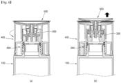
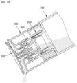
- FIGS. 6 to 8 illustrate exemplary operations of the content container according to the embodiment of the present invention.
- FIG. 7(a) is a cross-sectional view of the content container 1000 when the cover part 500 is in the first position
- FIG. 7(b) is a cross-sectional view of the content container 1000 when the cover part 500 is in the second position.
- FIG. 8(a) is a perspective view of the content container 1000 when the cover part 500 is in the first position, showing the interior of the rotating part 400
- FIG. 8(b) is a perspective view of the content container 1000 when the cover part 500 is in the second position, showing the interior of the rotating part 400.
- FIG. 9 illustrates the tilted state of the content container 1000 when the cover part 500 is in the second position.
- the lower portion of the container part 100 is omitted in FIGS. 7 to 9 .
- the lifting protrusion 320 when the user rotates the rotating part 400, the vertical groove 421 of the rotating part 400 rotates. At this time, the lifting protrusion 320 also rotates along with the vertical groove 421, and in this instance, the lifting protrusion 320 rotates together with the vertical groove 421 and the lifting part 300 rotates synchronously with the rotating part 400. In this instance, the lifting protrusion 320 moves along the guide groove 231 while rotating, so the lifting protrusion 320 is lifted inside the shoulder part 200.
- the cover part 500 coupled to the lifting part 300 is also lifted together with the lifting part 300, so that the cover part 500 is lifted between the first position where the cover part is in close contact with the rotating part 400 and the second position where the cover part is separated from the rotating part 400.
- the first blocking part 350 When the cover part 500 is in the first position, the first blocking part 350 is in close contact with the inside of the communication tube 210, and the second blocking part 520 is in close contact with the inside of the discharge tube 410, thereby blocking the movement of contents to the communication hole 311 and the discharge to the outside through the discharge hole 411.
- the cover part 500 ascends to the second position due to the rotation of the rotating part 400, the first blocking part 350 is separated from the communication tube 210, and the second blocking part 520 is separated from the discharge tube 410, thereby allowing the discharge to the outside.
- the sealing tube 330 is always in close contact with the inside of the sealing wall 220 and the discharge tube 410, thereby preventing the contents from leaking out and ensuring that the contents always move only within the sealing wall 220, the sealing tube 330, and the discharge tube 410.
- the rotation limitation protrusion 430 when the cover part 500 is in the first position, the rotation limitation protrusion 430 is positioned between the first limitation jaw 271 and the first retaining protrusion 281. In this case, since one side of the rotation limitation protrusion 430 is in contact with the first limitation jaw 271, movement toward the side of the first limitation jaw 271 is blocked, thereby limiting rotation of the rotating part 400 in the first direction.
- the rotation limitation protrusion 430 can pass over the first retaining protrusion 281.
- a force greater than a predetermined magnitude must be applied to the rotating part 400.
- the first retaining protrusion 281 maintains the position of the rotation limitation protrusion 430.
- the rotation limitation protrusion 430 moves toward the second retaining protrusion 281.
- the rotation limitation protrusion 430 can pass over the second retaining protrusion 282, but a force greater than a predetermined magnitude must be applied to the rotating part 400.
- the second retaining protrusion 282 limits the movement of the rotation limitation protrusion 430.
- the rotating part 400 rotates further in the second direction, so the cover part 500 moves to the second position.
- the rotation limitation protrusion 430 is positioned between the second limitation jaw 272 and the second retaining protrusion 282. Since not the one side but the other side of the rotation limitation protrusion 430 gets in contact with the second limitation jaw 272, movement toward the side of the second limitation jaw 272 is blocked, so rotation of the rotating part 400 in the second direction is limited.
Landscapes
- Engineering & Computer Science (AREA)
- Mechanical Engineering (AREA)
- Closures For Containers (AREA)
Abstract
Description
- The present disclosure relates to a content container.
- Cosmetics can be categorized into basic cosmetics, makeup cosmetics, hair care cosmetics, fragrances, medicinal cosmetics, etc., depending on the functions, and are distinguished into cream, powder, and liquid depending on the states and are stored in suitable containers.
- Among them, in case of containers storing liquid contents, there are liquid content containers in which liquid contents are naturally discharged to the outside through an opening by the force of gravity when a user tilts the container. The liquid content containers includes: a container part storing liquid contents; an opening part positioned at the upper portion of the container part to discharge the liquid contents to the outside; and a cover opening and closing the opening part.
- However, the conventional liquid containers that discharge contents by tilting the container have a disadvantage in that when the container is erected after tilted to discharge the contents, the liquid contents are pooled in the top of the opening part or flow down outwardly from the opening part, thus causing contamination of the container.
- Therefore, there is a need for a content container that can prevent the liquid contents from being pooled in the opening part and from flowing down outwardly from the opening part.
- Accordingly, the present invention has been made in view of the above-mentioned problems occurring in the related art, and it is an object of the present invention to provide a content container.
- The objects of the present invention are not limited to those mentioned above, and other objects not mentioned herein will be clearly understood by those skilled in the art from the following description.
- To accomplish the above-mentioned objects, according to the present invention, there is provided a content container including: a container part that accommodates contents and has a spout portion formed on the upper side thereof; a shoulder part that is coupled to the upper side of the container part and has a communication space through which the contents move inwardly; a lifting part that is coupled to the inner side of the shoulder part, moves vertically with respect to the shoulder part by rotation, and has at least one communication hole through which the contents move; a rotating part that is coupled to the outer side of the shoulder part, has a discharge hole formed in the upper side thereof for discharging the contents transferred from the communication hole, and rotates the lifting part while being rotated; and a cover part that is coupled to the upper side of the lifting part, and ascends and descends between a first position which seals the discharge hole while coming into close contact with the rotating part and a second position which opens the discharge hole while being separated from the rotating part, depending on the ascent and descent of the lifting part.
- Moreover, when a user tilts the content container in a state in which the cover part is moved in the second position, the contents passes through the discharge hole and is discharged into a space between the cover part and the rotating part.
- Furthermore, the lifting part comprises at least one lifting protrusion formed on the side. The shoulder part comprises a first guide part which is placed on the upper side of the spout portion and has at least one guide groove into which the lifting protrusion is inserted When the rotating part rotates, the lifting protrusion moves along the guide groove so that the lifting part is lifted at the same time with rotation.
- Additionally, the rotating part comprises a second guide part which is arranged on the outer side of the first guide part and has at least one vertical groove into which the lifting protrusion is inserted. When the rotating part rotates, the lifting protrusion moves along the vertical groove so that the rotating part and the lifting part rotate synchronously and the lifting part ascends and descends with respect to the rotating part.
- In addition, the shoulder part further comprises a communication tube, which is penetrated vertically to form a communication space therein and allows the lifting part to be placed on the upper side thereof, The lifting part further comprises a guide protrusion protruding downward from a docking part placed in the communication tube to a predetermined length. The communication hole is arranged on the outer side of the guide protrusion so that the movement of the contents to the communication hole is guided by the guide protrusion.
- Moreover, the lifting part further comprises a coupling protrusion protruding upward from the docking part and coupling with the cover part.
- Furthermore, the shoulder part further comprises a sealing wall positioned outward from the communication tube, and the lifting part further comprises a first sealing tube of a soft material extending downward from the periphery of the docking part to gradually increase the diameter downward, thereby getting in close contact with at least a portion of the inner side of the sealing wall.
- Additionally, the lifting part further comprises a first blocking part extending downward from the docking part outside the guide protrusion, getting in close contact with the inner surface of the communication tube when the cover part is in the first position, and being separated from the communication tube when the cover part is in the second position. The at least one communication hole is formed between the first sealing tube and the first blocking part.
- In addition, on the upper surface of the shoulder part, formed are: at least one limitation jaw getting in contact with at least one rotation limitation protrusion formed on the rotating part to limit the rotation radius of the rotating part; and at least one maintaining protrusion spaced apart from the limitation jaw and formed to maintain the arrangement of the rotation limitation protrusion in contact with the limitation jaw.
- Moreover, the rotating part further comprises a discharge tube arranged on the upper side of the lifting part, and penetrated vertically to form the discharge hole therein. The lifting part further comprises a second sealing tube of a soft material, extending upward from the periphery of the docking part placed on the shoulder part to gradually increase the diameter upward, thereby getting in close contact with at least a portion of the inner side of the discharge tube.
- Furthermore, the cover part further comprises a second blocking part extending downward from the upper surface, getting in close contact with the inner side of the discharge tube when the cover part is in the first position, and being separated from the discharge tube when the cover part is in the second position.
- Additionally, the upper surface of the rotating part is formed with a curved shape that the height and surface area increase outward.
- In addition, on the periphery of the rotating part, a rim part is formed to extend outward with a predetermined slope with respect to the upper surface of the rotating part, thereby preventing the contents from flowing down along the outer peripheral surface of the rotating part.
- Furthermore, the content container further includes a blocking plug coupled to the spout portion to block the inflow of contents into the shoulder part, and removed when initially used.
- According to an embodiment of the present invention, the content container is configured to discharge the contents by raising and lowering the cover part with a simple rotating manipulation, thereby preventing liquid contents from pooling in the opening and from flowing down outward from the opening part.
- Additionally, according to the present invention, when the cover part is raised, the shoulder part, the lifting part, and the rotating part which are the internal structure of the content container can be maintained in the close contact state with each other, thereby preventing leakage of contents from the content container.
- Furthermore, according to the present invention, the content container can naturally discharge the content to the outside due to the curved shape of the upper surface of the cover part.
- Moreover, according to the present invention, the content container includes the rim part with a predetermined slope formed on the circumference of the rotating part to prevent the contents from flowing down outward from the container, thereby providing a clean user experience.
- In addition, according to the present invention, the content container includes the guide protrusion protruding on the lower side of the lifting part to guide the contents introduced from the shoulder part to the lifting part to move into the communication hole, thereby creating a more natural fluid flow.
- A brief description of each drawing is provided for better understanding of the drawings referred to in the detailed description of the present invention.
-
FIG. 1 is a perspective view of a content container according to an embodiment of the present invention. -
FIG. 2 is an exploded perspective view of the content container according to the embodiment of the present invention. -
FIG. 3 is a cross-sectional view of the content container according to the embodiment of the present invention. -
FIG. 4 is a perspective view of a rotating part according to the embodiment of the present invention. -
FIG. 5 is a perspective view of a lifting part according to the embodiment of the present invention. -
FIGS. 6 to 8 illustrate exemplary operations of the content container according to the embodiment of the present invention. - Hereinafter, exemplary embodiments according to the present disclosure will be described in detail with reference to the contents disclosed in the accompanying drawings. In addition, a method of configuring and using an apparatus according to an embodiment of the present disclosure will be described in detail with reference to the contents disclosed in the accompanying drawings. Like reference numerals or symbols illustrated in the drawings designate parts or components that perform substantially the same functions. For convenience of description, the upward, downward, leftward, and rightward directions are based on the drawings, and the scope of the present disclosure is not necessarily limited in the corresponding directions.
- It will be understood that terms, such as "first" or "second" may be used in the specification to describe various components but are not restricted to the above terms. The terms may be used to discriminate one component from another component. For instance, the first component may be named as the second component, and on the contrary, the second component may be also named as the first component within the scope of the present disclosure. The term, "and/or", includes a combination of a plurality of related items or any one item among the plurality of related items.
- It will be further understood that the words or terms used in the present disclosure are used to describe specific embodiments of the present disclosure and there is no intent to limit the present disclosure. The singular form of the components may be understood into the plural form unless otherwise specifically stated in the context. It should be also understood that the terms of `include' or 'have' in the specification are used to mean that there are characteristics, numbers, steps, operations, components, parts, or combinations of the steps, operations, components and parts described in the specification and there is no intent to exclude existence or possibility of other characteristics, numbers, steps, operations, components, parts, or combinations of the steps, operations, components and parts.
- Throughout the specification, when a portion is connected to another portion, it may be directly connected to the other portion, or may be indirectly connected to the other portion with another configuration interposed therebetween. In addition, when a portion includes a component, it means that other components may be further included, rather than excluding other components unless otherwise stated.
-
FIG. 1 is a perspective view of a content container according to an embodiment of the present invention,FIG. 2 is an exploded perspective view of the content container according to the embodiment of the present invention,FIG. 3 is a cross-sectional view of the content container according to the embodiment of the present invention,FIG. 4 is a perspective view of a rotating part according to the embodiment of the present invention, andFIG. 5 is a perspective view of a lifting part according to the embodiment of the present invention. InFIG. 3 , the lower portion of the container part is omitted for convenience. - Referring to
FIGS. 1 to 5 , acontent container 1000 according to an embodiment of the present invention may include acontainer part 100; ashoulder part 200; alifting part 300; arotating part 400; and acover part 500. - The
container part 100 can accommodate contents. The contents may be cosmetics in liquid, gel, or powder type. For example, the contents may include lotion, milk lotion, moisture lotion, nutrient lotion, skin lotion, skin softener, skin toner, astringent, massage cream, nutrient cream, moisture cream, whitening essence, tone-up cream, sunscreen, sun milk, BB cream, base, foundation, CC cream, concealer, blusher, shading, eyeshadow, eyebrow product, eye cream, primer, etc. However, the contents are not limited thereto, and other formulations or other types of cosmetics, pharmaceuticals, or non-pharmaceutical products may also be included. - In an embodiment, the
container part 100 may have aspout portion 110 formed on the upper side thereof. Thespout portion 110 is opened at the upper side, such that the contents may be discharged upward from thecontainer part 100 through thespout portion 110 or may be introduced into thecontainer part 100. For instance, theshoulder part 200 may be coupled to thespout portion 110, and the contents discharged upward through thespout portion 110 may be introduced into theshoulder part 200. A screw coupling portion for detachably coupling theshoulder part 200 may be formed on the outer peripheral surface of thespout portion 110. - The
shoulder part 200 may guide the lifting of the liftingpart 300, and control the discharge of contents to the outside. For example, theshoulder part 200 may be coupled to thespout portion 110 of thecontainer part 100, and a communication space may be provided to allow the contents to move inward. In a state in which thelifting part 300 is lowered, introduction of the contents from thecontainer part 100 to theshoulder part 200 is blocked. However, in a state in which thelifting part 300 is raised, introduction of the contents from thecontainer part 100 to theshoulder part 200 is allowed. - In an embodiment, the
shoulder part 200 may include: acommunication tube 210; a sealingwall 220; afirst guide part 230; and/or apressure part 240. - The
communication tube 210 may penetrate vertically to form an inward communication space and may be arranged on the upper side of thespout portion 110. Additionally, the liftingpart 300 may be placed on the upper side of thecommunication tube 210. In this case, the liftingpart 300 can adjust the discharge of the contents while getting contact with and being separated from the end of thecommunication tube 210. - The sealing
wall 220 is in close contact with the liftingpart 300, especially thefirst sealing tube 331, so that contents always move only within theshoulder part 200 and the liftingpart 300 inwardly without leaking to the outside. Moreover, even when the liftingpart 300 is raised, the contact between the sealingwall 220 and the liftingpart 300, especially thefirst sealing tube 331, can be maintained. For example, the sealingwall 220 may be placed on the upper side of thespout portion 110, specifically, on the upper side of thespout portion 110 and the outer side of thecommunication tube 210. - The
first guide part 230 can guide the lifting of the liftingpart 300. For this purpose, thefirst guide part 230 may have at least oneguide groove 231, and the liftingprotrusion 320 of the liftingpart 300 may be inserted into theguide groove 231. As the liftingprotrusion 320 moves along theguide groove 231, the liftingpart 300 can be raised at the same time with rotation. For example, thefirst guide part 230 may be positioned on the upper side of thespout portion 110, and more specifically, on the upper side of thespout portion 110 and on the the outer side of the communication tube 210 (and the sealing wall 220). - The
pressure part 240 protrudes downward from theshoulder part 200, and can pressurize thecontainer part 100 when theshoulder part 200 is coupled to thespout portion 110. Thus, the sealing between theshoulder part 200 and thecontainer part 100 is enhanced, and leakage of contents along the coupling area between thecontainer part 100 and theshoulder part 200 can be prevented. - In an embodiment, the
shoulder part 200 can be coupled to thespout portion 110 via acontainer coupling part 250, and can be rotatably coupled to therotating part 400 via arotation coupling part 260. For example, thecontainer coupling part 250 may be formed along the outer side of thespout portion 110 for coupling with thespout portion 110 via screw coupling, and therotation coupling part 260 may be positioned on the outer side of thecontainer coupling part 250 for coupling with therotating part 400 via snap-fit coupling. However, the coupling method of the present invention is not limited thereto, and various coupling methods such as screw coupling, snap-fit coupling, hook coupling, interlocking coupling, or dovetail coupling as disclosed may be applied depending on the embodiment. - In an embodiment, on the upper surface of the
shoulder part 200, especially between thecontainer coupling part 250 and therotation coupling part 260, at least onelimitation jaw 270 and at least one maintainingprotrusion 280 may be formed, wherein the at least one maintainingprotrusion 280 is in contact with at least onerotation limitation protrusion 430 formed on therotating part 400 and restricts the rotation radius of therotating part 400, and the at least one maintainingprotrusion 280 is spaced apart from thelimitation jaw 270 and maintains the arrangement of therotation limitation protrusion 430 when therotation limitation protrusion 430 is in contact with thelimitation jaw 270. - In an embodiment, when the user rotates the
rotating part 400 in a specific direction (specifically, a direction that causes therotation limitation protrusion 430 to move toward the limitation jaw 270) in the state in which therotation limitation protrusion 430 is in contact with thelimitation jaw 270, therotation limitation protrusion 430 and thelimitation jaw 270 can move together, thereby causing synchronous rotation of therotating part 400 and theshoulder part 200. When therotating part 400 and theshoulder part 200 rotate synchronously, the shoulder part 200 (and the liftingpart 300,rotating part 400, and coverpart 500 directly or indirectly coupled to the shoulder part 200) can be separated from or coupled to thecontainer part 100. - In an embodiment, the
rotation limitation protrusion 430 may pass over the maintainingprotrusion 280, but a force greater than a predetermined size may need to be applied to therotating part 400. That is, when a force smaller than a predetermined size is applied to therotating part 400, the maintainingprotrusion 280 can restrict the movement of therotation limitation protrusion 430. - In an embodiment, at least one of the maintaining
protrusions 280 is elastically deformed and moves downward during rotation of therotating part 400, thereby allowing rotation of therotating part 400 with less force applied. - In an embodiment, the
limitation jaw 270 may include: afirst limitation jaw 271; and asecond limitation jaw 272 spaced apart from thefirst limitation jaw 271 at a predetermined distance. Thefirst limitation jaw 271 is in contact with one side of therotation limitation protrusion 430, and blocks the movement of therotation limitation protrusion 430 towards thefirst limitation jaw 271 to limit the rotation of therotating part 400 in one direction. Additionally, thesecond limitation jaw 272 is in contact with the other side of therotation limitation protrusion 430, and blocks the movement of therotation limitation protrusion 430 towards thesecond limitation jaw 272 to limit the rotation of therotating part 400 in the other direction. - In an embodiment, when the user rotates the
rotating part 400 in the other direction in the state in which theshoulder part 200 is coupled to thecontainer part 100 and therotation limitation protrusion 430 is in contact with thesecond limitation jaw 272, therotating part 400 and theshoulder part 200 rotate synchronously and theshoulder part 200 can be separated from thecontainer part 100. Additionally, when the user rotates therotating part 400 in one direction in the state in which theshoulder part 200 is separated from thecontainer part 100 and therotation limitation protrusion 430 is in contact with thefirst limitation jaw 271, therotating part 400 and theshoulder part 200 rotate synchronously and theshoulder part 200 can be coupled to thecontainer part 100. - In an embodiment, the maintaining
protrusion 280 may include: a first maintainingprotrusion 281 spaced apart from thefirst limitation jaw 271 at a predetermined distance; and a second maintainingprotrusion 282 spaced apart from thesecond limitation jaw 272 at a predetermined distance. The first maintainingprotrusion 281 may be positioned on the other side of therotation limitation protrusion 430 when one side of therotation limitation protrusion 430 is in contact with thefirst limitation jaw 271, thereby maintaining the position of therotation limitation protrusion 430. The second maintainingprotrusion 282 may be positioned on one side of therotation limitation protrusion 430 when the other side of therotation limitation protrusion 430 is in contact with thesecond limitation jaw 272, thereby maintaining the position of therotation limitation protrusion 430. - In an embodiment, the first maintaining
protrusion 281 may be elastically deformed and move downward during rotation of therotating part 400, but the second maintainingprotrusion 282 is not elastically deformed during rotation of therotating part 400. This is to differentiate the force to be applied to therotating part 400 to lift thecover part 500 from the first position to the second position (i.e., the force required for therotation limitation protrusion 430 to pass over the first maintaining protrusion 281) and the force to be applied to therotating part 400 to separate theshoulder part 200 from the container part 100 (i.e., the force required for therotation limitation protrusion 430 to pass over the second maintaining protrusion 282) so that the user can intuitively percept the degree of manipulation of therotating part 400. - The lifting
part 300 can ascend and regulate whether the contents are discharged to the outside. For example, the liftingpart 300 can be coupled to the inner side of theshoulder part 200 and ascend with respect to theshoulder part 200 while rotating due to the rotation of therotating part 400. - In an embodiment, the lifting
part 300 may include adocking part 310, a liftingprotrusion 320, a sealingtube 330, aguide protrusion 340, afirst blocking part 350, and/or acoupling protrusion 360. - The
docking part 310 may be placed on the upper side of thecommunication tube 210 of theshoulder part 200. When thedocking part 310 is placed on thecommunication tube 210, the discharge of contents may be blocked, and when thedocking part 310 is separated from thecommunication tube 210, the discharge of contents may be permitted. - The
docking part 310 may have at least onecommunication hole 311 formed to allow movement of contents. Thus, the contents transferred from thecontainer part 100 to the liftingpart 300 via thecommunication tube 210 and/orspout portion 110 can be discharged upward over the liftingpart 300 through thecommunication hole 311. - The lifting
protrusion 320 may protrude on the side of the liftingpart 300. The liftingprotrusion 320 may be inserted into aguide groove 231 formed in thefirst guide part 230 of theshoulder part 200 and/or avertical groove 421 formed in thesecond guide part 420 of therotating part 400. This is to synchronize the rotation of the liftingpart 300 with therotating part 400 during rotation of therotating part 400 and to lift the liftingpart 300 with respect to theshoulder part 200 when the liftingpart 300 rotates. For example, the liftingprotrusion 320 may protrude outward from thedocking part 310. - The sealing
tube 330 can be in close contact with the shoulder part 200 (especially, the sealing wall 220) and/or the rotating part 400 (especially, the discharge tube 410), such that the contents always move only inside theshoulder part 200, the liftingpart 300, and therotating part 400, thereby preventing leakage to the outside. In this case, since at least a portion of the sealingtube 330 may be formed of a soft material capable of being elastically deformed, the sealingtube 330 can maintain the contact state with the sealingwall 220 and/or thedischarge tube 410 despite the lifting of the liftingpart 300. For instance, at least a portion of the sealingtube 330 may be formed of polyethylene (PE) material, but is not limited thereto, and various resilient materials may be applied. - In an embodiment, the sealing
tube 330 may include: afirst sealing tube 331 extending downward from the perimeter of thedocking part 310; and asecond sealing tube 332. Thefirst sealing tube 331 may be in close contact with at least a portion of the inner side of the sealingwall 220, and since the diameter increases toward the bottom, the contact with the sealingwall 220 can be achieved effectively. In addition, thesecond sealing tube 332 may be in close contact with at least a portion of the inner side of thedischarge tube 410, and since the diameter increases toward the top, the contact with thedischarge tube 410 can be achieved effectively. - The
guide protrusion 340 may protrude downward from thedocking part 310. In this case, thecommunication hole 311 may be arranged on the outer side of theguide protrusion 340, and the movement of the contents to thecommunication hole 311 may be guided by theguide protrusion 340. That is, the contents passing through thecommunication tube 210 may be distributed towards thecommunication hole 311 while colliding with theguide protrusion 340, thereby ensuring smooth movement of the contents and natural fluid flow. - In an embodiment, to be positioned inside the
communication tube 210 even at maximum lifting of the liftingpart 300, theguide protrusion 340 may protrude a predetermined length from thedocking part 310. Thus, regardless of the lifting of the liftingpart 300, theguide protrusion 340 can always guide the movement of the contents to thecommunication hole 311. - The
first blocking part 350 may block the movement of contents from theshoulder part 200 to the liftingpart 300 during descent of the lifting part 300 (i.e., when thecover part 500 is in the first position), but allow movement of the contents from theshoulder part 200 to the liftingpart 300 during ascent of the lifting part 300 (i.e., when thecover part 500 is in the second position). For this purpose, for example, thefirst blocking part 350 may extend downward from the outer side of theguide protrusion 340 to thedocking part 310, and is in close contact with the inner side of thecommunication tube 210 during descent (i.e., when thecover part 500 is in the first position), but is separated from thecommunication tube 210 during ascent (i.e., when thecover part 500 is in the second position). - In an embodiment, at least one
communication hole 311 may be formed between the sealingtube 330 and thefirst blocking part 350. As a result, in the state in which thedocking part 310 is placed in thecommunication tube 210, the contents may not flow into thecommunication hole 311 due to thefirst blocking part 350, but when thedocking part 310 is separated from thecommunication tube 210, the contents may flow into thecommunication hole 311. - The
coupling protrusion 360 may protrude upward from thedocking part 310, and can couple with the cover part 500 (especially, the coupling tube 510). For example, thecoupling protrusion 360 may have at least one fitting protrusion formed on the outer peripheral surface thereof, and the liftingpart 300 and thecover part 500 can be coupled when thecoupling protrusion 360 is coupled to the inner side of thecoupling tube 510. However, the coupling protrusion is not limited thereto, and various coupling structures as known in the art may be applied to the coupling between the liftingpart 300 and thecover part 500. - The
rotating part 400 is coupled to the outer side of theshoulder part 200, and can rotate the liftingpart 300 by being rotated. So, the liftingpart 300 is lifted from the inner side of theshoulder part 200. Additionally, therotating part 400 may have adischarge hole 411 formed on the upper side to discharge the contents delivered from thecommunication hole 311. - In an embodiment, the
rotating part 400 may include: adischarge tube 410, asecond guide part 420, and/or arotation limitation protrusion 430. - The
discharge tube 410 may be positioned on the upper side of the liftingpart 300, and may be penetrated vertically to form adischarge hole 411 therein. The contents introduced into the liftingpart 300 can be discharged to the outside through thedischarge tube 410. - In an embodiment, the
discharge tube 410 may be in close contact with thesecond sealing tube 332 of the liftingpart 300, so that the contents always move only within the liftingpart 300 and therotating part 400, thereby preventing leakage to the outside. Additionally, even during lifting of the liftingpart 300, the close contact between thedischarge tube 410 and thesecond sealing tube 332 can be maintained. - The
second guide part 420 can synchronize the rotation of the liftingpart 300 with the rotation of therotating part 400 when therotating part 400 rotates. For this purpose, at least onevertical groove 421 may be formed in thesecond guide part 420, and the liftingprotrusion 320 of the liftingpart 300 may be inserted into thevertical groove 421. When therotating part 400 rotates, the liftingprotrusion 320 can rotate synchronously with thevertical groove 421, thereby allowing the liftingprotrusion 320 to lift along thevertical groove 421. For example, thesecond guide part 420 may extend downward from the upper surface of therotating part 400 to be positioned on the outer side of thefirst guide part 230, but is not limited thereto. Thesecond guide part 420 may also be positioned on thefirst guide part 230. - The
rotation limitation protrusion 430 may protrude, for example, outward and/or downward from one side of thesecond guide part 420. Therotation limitation protrusion 430 can come into contact with thelimitation jaw 270 of theshoulder part 200 to limit the rotation radius of therotating part 400, and can come into contact with the retainingprotrusion 280 to maintain the arrangement. - In an embodiment, the upper surface of the
rotating part 400 may be formed with a curved shape that the height and surface area increase outward. Accordingly, the contents discharged through thedischarge tube 410 can smoothly flow outward along the curved surface of the upper surface of therotating part 400. - In an embodiment, a
rim part 440 may be formed around the periphery of the upper surface of therotating part 400. Therim part 440 may extend outward from the periphery of the upper surface of therotating part 400 and may be formed with a predetermined slope in the upward direction. Additionally, according to an embodiment, at least one stepped jaw may be further formed on the inner side of therim part 440. Therim part 440 can prevent the contents from flowing down along the outer peripheral surface of therotating part 400 during the discharge process. For example, while the contents move along the upper surface of therotating part 400 and are discharged outward, when the user changes the tilted angle of thecontent container 1000 to interrupt the discharge of the contents, therim part 400 protruding upward and outward prevent the contents from being stained on the outer surface of thecontent container 1000, thereby providing a neat user experience. - The
cover part 500 can be coupled to the upper surface of the liftingpart 300, and can ascend and descend between the first position where the cover part seals thedischarge hole 411 while coming into close contact with therotating part 400 and the second position where the cover part opens thedischarge hole 411 while being separated from therotating part 400 depending on the ascent and descent of the liftingpart 300. When the user tilts thecontent container 1000 in the state in which thelifting part 300 moves to the second position, the contents can be discharged through thedischarge hole 411 into the space between thecover part 500 and therotating part 400. - In an embodiment, the
cover part 500 may include acoupling tube 510, and/or asecond blocking part 520. - The
coupling tube 510 protrudes downward from thecover part 500, and have a passage for inserting thecoupling protrusion 360 inwardly. In this case, thecoupling protrusion 360 may have at least one recess formed on the inner side thereof. As thecoupling protrusion 360 is inserted into thecoupling tube 510, the liftingpart 300 can be coupled with thecover part 500. However, the coupling tube is not limited thereto, and various coupling structures may be applied to the coupling of the liftingpart 300 and thecover part 500. - The
second blocking part 520 may block the discharge of contents from thedischarge tube 410 when thecover part 500 is in the first position, but allow the discharge of contents when thecover part 500 is in the second position. For this purpose, for example, thesecond blocking part 520 may extend downward from the upper surface of thecover part 500 on the outer side of thecoupling tube 510. When thecover part 500 is in the first position, the second blocking part may be in close contact with the inner surface of thedischarge tube 410, but when thecover part 500 is in the second position, it may be separated from thedischarge tube 410. - In an embodiment, the bottom surface of the
cover part 500 may be shaped to correspond to the top surface of therotating part 400, thereby enhancing the sealing performance. - According to an embodiment, the
content container 1000 may further include a blockingplug 600 which is coupled to thespout portion 110 to block the inflow of contents into theshoulder part 200, and is removed when initially used. - In an embodiment, at the time of the initial use of the
content container 1000, the user rotates therotating part 400 and makes therotation limitation protrusion 430 be in contact with the limitation jaw 270 (especially, the second limitation jaw 272), then continuously rotates therotating part 400 in the same direction to separate theshoulder part 200 from thecontainer part 100, and then, removes the blockingplug 600 from thespout portion 110. The user can then recouple theshoulder part 200 to thecontainer part 100 from which the blockingplug 600 has been removed, and use thecontent container 1000. -
FIGS. 6 to 8 illustrate exemplary operations of the content container according to the embodiment of the present invention. Specifically,FIG. 7(a) is a cross-sectional view of thecontent container 1000 when thecover part 500 is in the first position, andFIG. 7(b) is a cross-sectional view of thecontent container 1000 when thecover part 500 is in the second position. Additionally, FIG. 8(a) is a perspective view of thecontent container 1000 when thecover part 500 is in the first position, showing the interior of therotating part 400, and FIG. 8(b) is a perspective view of thecontent container 1000 when thecover part 500 is in the second position, showing the interior of therotating part 400. Furthermore, FIG. 9 illustrates the tilted state of thecontent container 1000 when thecover part 500 is in the second position. For convenience, the lower portion of thecontainer part 100 is omitted inFIGS. 7 to 9 . - Referring to
FIG. 7 , when the user rotates therotating part 400, thevertical groove 421 of therotating part 400 rotates. At this time, the liftingprotrusion 320 also rotates along with thevertical groove 421, and in this instance, the liftingprotrusion 320 rotates together with thevertical groove 421 and the liftingpart 300 rotates synchronously with therotating part 400. In this instance, the liftingprotrusion 320 moves along theguide groove 231 while rotating, so the liftingprotrusion 320 is lifted inside theshoulder part 200. When the liftingpart 300 is lifted, thecover part 500 coupled to the liftingpart 300 is also lifted together with the liftingpart 300, so that thecover part 500 is lifted between the first position where the cover part is in close contact with therotating part 400 and the second position where the cover part is separated from therotating part 400. - When the
cover part 500 is in the first position, thefirst blocking part 350 is in close contact with the inside of thecommunication tube 210, and thesecond blocking part 520 is in close contact with the inside of thedischarge tube 410, thereby blocking the movement of contents to thecommunication hole 311 and the discharge to the outside through thedischarge hole 411. When thecover part 500 ascends to the second position due to the rotation of therotating part 400, thefirst blocking part 350 is separated from thecommunication tube 210, and thesecond blocking part 520 is separated from thedischarge tube 410, thereby allowing the discharge to the outside. Regardless of the lifting of thecover part 500, the sealingtube 330 is always in close contact with the inside of the sealingwall 220 and thedischarge tube 410, thereby preventing the contents from leaking out and ensuring that the contents always move only within the sealingwall 220, the sealingtube 330, and thedischarge tube 410. - Referring to
FIG. 8 , when thecover part 500 is in the first position, therotation limitation protrusion 430 is positioned between thefirst limitation jaw 271 and thefirst retaining protrusion 281. In this case, since one side of therotation limitation protrusion 430 is in contact with thefirst limitation jaw 271, movement toward the side of thefirst limitation jaw 271 is blocked, thereby limiting rotation of therotating part 400 in the first direction. When therotating part 400 is rotated in a direction different from the first direction, therotation limitation protrusion 430 can pass over thefirst retaining protrusion 281. However, a force greater than a predetermined magnitude must be applied to therotating part 400. When a force less than the predetermined magnitude is applied to therotating part 400, thefirst retaining protrusion 281 maintains the position of therotation limitation protrusion 430. - Subsequently, when the user continuously rotates the
rotating part 400 in the second direction, therotation limitation protrusion 430 moves toward thesecond retaining protrusion 281. At this point, when the user continuously rotates therotating part 400, therotation limitation protrusion 430 can pass over thesecond retaining protrusion 282, but a force greater than a predetermined magnitude must be applied to therotating part 400. When a force less than the predetermined magnitude is applied to therotating part 400, thesecond retaining protrusion 282 limits the movement of therotation limitation protrusion 430. As the force greater than the predetermined magnitude is applied, therotating part 400 rotates further in the second direction, so thecover part 500 moves to the second position. Then, therotation limitation protrusion 430 is positioned between thesecond limitation jaw 272 and thesecond retaining protrusion 282. Since not the one side but the other side of therotation limitation protrusion 430 gets in contact with thesecond limitation jaw 272, movement toward the side of thesecond limitation jaw 272 is blocked, so rotation of therotating part 400 in the second direction is limited. - Additionally, although not shown in
FIG. 8 , when the user further rotates therotating part 400 in the second direction, therotation limitation protrusion 430 and thesecond limitation jaw 272 move together, and therotating part 400 and theshoulder part 200 rotate synchronously, such that theshoulder part 200, the liftingpart 300, therotating part 400, and thecover part 500 are separated from thecontainer part 100. - Referring to FIG. 9, in the state in which the
cover part 500 is moved in the second position, when the user tilts thecontent container 1000, the contents are discharged externally through thecommunication tube 210, thecommunication hole 311, and thedischarge tube 410. At this point, theguide protrusion 340 of the liftingpart 300 guides the flow of contents into thecommunication hole 311. - As described above, the optimal embodiments has been disclosed in the drawings and the specification. Specific terms have been used herein for descriptive purposes, not for purposes of limitation of meanings or to limit the scope of the invention as set forth in the claims. Therefore, it would be understood by those skilled in the art that various modifications and equivalent embodiments are possible from the present disclosure. Accordingly, the true scope of protection of the present disclosure should be determined by the technical concept of the attached claims.
Claims (14)
- A content container comprising:a container part that accommodates contents and has a spout portion formed on the upper side thereof;a shoulder part that is coupled to the upper side of the container part and has a communication space through which the contents move inwardly;a lifting part that is coupled to the inner side of the shoulder part, moves vertically with respect to the shoulder part by rotation, and has at least one communication hole through which the contents move;a rotating part that is coupled to the outer side of the shoulder part, has a discharge hole formed in the upper side thereof for discharging the contents transferred from the communication hole, and rotates the lifting part while being rotated; anda cover part that is coupled to the upper side of the lifting part, and ascends and descends between a first position which seals the discharge hole while coming into close contact with the rotating part and a second position which opens the discharge hole while being separated from the rotating part, depending on the ascent and descent of the lifting part.
- The content container according to claim 1, wherein when a user tilts the content container in a state in which the cover part is moved in the second position, the contents passes through the discharge hole and is discharged into a space between the cover part and the rotating part.
- The content container according to claim 1, wherein the lifting part comprises at least one lifting protrusion formed on the side,wherein the shoulder part comprises a first guide part which is placed on the upper side of the spout portion and has at least one guide groove into which the lifting protrusion is inserted, andwherein when the rotating part rotates, the lifting protrusion moves along the guide groove so that the lifting part is lifted at the same time with rotation.
- The content container according to claim 3, wherein the rotating part comprises a second guide part which is arranged on the outer side of the first guide part and has at least one vertical groove into which the lifting protrusion is inserted, and
wherein when the rotating part rotates, the lifting protrusion moves along the vertical groove so that the rotating part and the lifting part rotate synchronously and the lifting part ascends and descends with respect to the rotating part. - The content container according to claim 1, wherein the shoulder part further comprises a communication tube, which is penetrated vertically to form a communication space therein and allows the lifting part to be placed on the upper side thereof, andwherein the lifting part further comprises a guide protrusion protruding downward from a docking part placed in the communication tube to a predetermined length, andwherein the communication hole is arranged on the outer side of the guide protrusion so that the movement of the contents to the communication hole is guided by the guide protrusion.
- The content container according to claim 5, wherein the lifting part further comprises a coupling protrusion protruding upward from the docking part and coupling with the cover part.
- The content container according to claim 5, wherein the shoulder part further comprises a sealing wall positioned outward from the communication tube, and
wherein the lifting part further comprises a first sealing tube of a soft material extending downward from the periphery of the docking part to gradually increase the diameter downward, thereby getting in close contact with at least a portion of the inner side of the sealing wall. - The content container according to claim 7, wherein the lifting part further comprises a first blocking part extending downward from the docking part outside the guide protrusion, getting in close contact with the inner surface of the communication tube when the cover part is in the first position, and being separated from the communication tube when the cover part is in the second position, and
wherein the at least one communication hole is formed between the first sealing tube and the first blocking part. - The content container according to claim 1, wherein on the upper surface of the shoulder part, formed are: at least one limitation jaw getting in contact with at least one rotation limitation protrusion formed on the rotating part to limit the rotation radius of the rotating part; and
at least one maintaining protrusion spaced apart from the limitation jaw and formed to maintain the arrangement of the rotation limitation protrusion in contact with the limitation jaw. - The content container according to claim 1, wherein the rotating part further comprises a discharge tube arranged on the upper side of the lifting part, and penetrated vertically to form the discharge hole therein, and
wherein the lifting part further comprises a second sealing tube of a soft material, extending upward from the periphery of the docking part placed on the shoulder part to gradually increase the diameter upward, thereby getting in close contact with at least a portion of the inner side of the discharge tube. - The content container according to claim 10, wherein the cover part further comprises a second blocking part extending downward from the upper surface, getting in close contact with the inner side of the discharge tube when the cover part is in the first position, and being separated from the discharge tube when the cover part is in the second position.
- The content container according to claim 1, wherein the upper surface of the rotating part is formed with a curved shape that the height and surface area increase outward.
- The content container according to claim 12, wherein on the periphery of the rotating part, a rim part is formed to extend outward with a predetermined slope with respect to the upper surface of the rotating part, thereby preventing the contents from flowing down along the outer peripheral surface of the rotating part.
- The content container according to claim 1, further comprising:
a blocking plug coupled to the spout portion to block the inflow of contents into the shoulder part, and removed when initially used.
Applications Claiming Priority (2)
| Application Number | Priority Date | Filing Date | Title |
|---|---|---|---|
| KR1020210150184A KR102719691B1 (en) | 2021-11-04 | 2021-11-04 | Container |
| PCT/KR2022/015367 WO2023080461A1 (en) | 2021-11-04 | 2022-10-12 | Contents container |
Publications (2)
| Publication Number | Publication Date |
|---|---|
| EP4428053A1 true EP4428053A1 (en) | 2024-09-11 |
| EP4428053A4 EP4428053A4 (en) | 2025-11-19 |
Family
ID=86241325
Family Applications (1)
| Application Number | Title | Priority Date | Filing Date |
|---|---|---|---|
| EP22890196.3A Pending EP4428053A4 (en) | 2021-11-04 | 2022-10-12 | CONTENTS CONTAINER |
Country Status (6)
| Country | Link |
|---|---|
| US (1) | US12232591B2 (en) |
| EP (1) | EP4428053A4 (en) |
| JP (1) | JP7698798B2 (en) |
| KR (1) | KR102719691B1 (en) |
| CN (1) | CN118139792A (en) |
| WO (1) | WO2023080461A1 (en) |
Families Citing this family (1)
| Publication number | Priority date | Publication date | Assignee | Title |
|---|---|---|---|---|
| WO2025257512A1 (en) | 2024-06-13 | 2025-12-18 | Medicos Chassal | Rechargeable multidose applicator |
Family Cites Families (19)
| Publication number | Priority date | Publication date | Assignee | Title |
|---|---|---|---|---|
| JPS54168258U (en) * | 1978-05-17 | 1979-11-27 | ||
| JPH0547103Y2 (en) * | 1987-03-26 | 1993-12-10 | ||
| FR2644432B2 (en) * | 1988-05-11 | 1991-06-14 | Morel Simone | ROTATING ENVELOPE CAPSULE FOR VIALS AND SIMILAR CONTAINERS |
| JP3605431B2 (en) * | 1995-03-03 | 2004-12-22 | エム・エフ・ヴィ株式会社 | Liquid container spout device |
| FR2777546B1 (en) * | 1998-04-21 | 2000-05-12 | Oreal | METERING TIP |
| USH2044H1 (en) * | 1998-11-02 | 2002-09-03 | Mcneil-Ppc, Inc. | Container with retaining member |
| DE202007001733U1 (en) | 2007-02-01 | 2007-07-12 | Mauer Ag | Central rotary closure |
| FR2945518B1 (en) * | 2009-05-18 | 2011-05-27 | Maitrise & Innovation | ANTI-DROP CAP WITH MOBILE CAP REMOVAL ELASTICALLY |
| KR101192211B1 (en) * | 2010-09-17 | 2012-10-17 | (주)연우 | Turning type Cosmetics Tube with Brush |
| KR101279910B1 (en) * | 2011-04-12 | 2013-07-05 | (주)에스엔피월드 | Discharge controller apparatus of fluid-material having rotation control stopper structure and cosmetic container having the same |
| KR101335570B1 (en) * | 2012-03-12 | 2013-12-02 | (주)연우 | Tube type cosmetic case |
| CN105916778B (en) | 2013-11-14 | 2018-08-07 | 阿帕达弗赖翁有限公司 | Distribution capping and the container covered with such distribution |
| KR102669851B1 (en) * | 2015-08-03 | 2024-05-28 | 가부시키가이샤 코세 | Sealing structure of container outlet |
| EP3162450A1 (en) * | 2015-11-02 | 2017-05-03 | Albea Thomaston Inc. | Dispensing device for dispensing a viscous or liquid product from a reservoir, and a receptacle comprising such a dispensing device |
| CH711731A1 (en) * | 2015-11-06 | 2017-05-15 | Hoffmann Neopac Ag | Locking system and container with locking system. |
| JP6679168B2 (en) | 2016-04-28 | 2020-04-15 | 株式会社吉野工業所 | Fixed volume dispensing container |
| KR101923180B1 (en) * | 2017-02-02 | 2018-11-29 | 주식회사 엘지생활건강 | Cosmetic vessel |
| KR101802133B1 (en) * | 2017-08-22 | 2017-11-28 | (주)연우 | Container for Discharging liquid type contents |
| KR102128583B1 (en) * | 2020-01-03 | 2020-07-08 | (주)연우 | Discharging container |
-
2021
- 2021-11-04 KR KR1020210150184A patent/KR102719691B1/en active Active
-
2022
- 2022-10-12 EP EP22890196.3A patent/EP4428053A4/en active Pending
- 2022-10-12 US US18/699,149 patent/US12232591B2/en active Active
- 2022-10-12 JP JP2024520002A patent/JP7698798B2/en active Active
- 2022-10-12 CN CN202280070715.7A patent/CN118139792A/en active Pending
- 2022-10-12 WO PCT/KR2022/015367 patent/WO2023080461A1/en not_active Ceased
Also Published As
| Publication number | Publication date |
|---|---|
| US20240389733A1 (en) | 2024-11-28 |
| JP2024533832A (en) | 2024-09-12 |
| WO2023080461A1 (en) | 2023-05-11 |
| CN118139792A (en) | 2024-06-04 |
| KR20230064727A (en) | 2023-05-11 |
| JP7698798B2 (en) | 2025-06-25 |
| EP4428053A4 (en) | 2025-11-19 |
| KR102719691B1 (en) | 2024-10-23 |
| US12232591B2 (en) | 2025-02-25 |
Similar Documents
| Publication | Publication Date | Title |
|---|---|---|
| EP3206527B1 (en) | Rotary-push type cosmetic container | |
| US5897263A (en) | Cosmetic dispensing package | |
| KR101333044B1 (en) | Compact case | |
| KR101619957B1 (en) | Cosmetic vessel having mixed two-type materials | |
| KR200496167Y1 (en) | Container | |
| JP2019535402A (en) | Rotating open / close type cosmetic container | |
| US12232591B2 (en) | Contents container | |
| EP3735856A1 (en) | Dropping pipette-type cosmetic container comprising pressing button having adjustable descending distance | |
| KR102619824B1 (en) | Container | |
| KR102265177B1 (en) | A spuit-typed cosmetic container | |
| KR102104248B1 (en) | Rotary opening and closing type cosmetic container | |
| KR101802133B1 (en) | Container for Discharging liquid type contents | |
| EP4487963A1 (en) | Contents container of which head part is raised and lowered by rotation | |
| KR102643868B1 (en) | Container | |
| KR101807294B1 (en) | Vessel with a dual applicator | |
| KR102693651B1 (en) | Container | |
| KR200460286Y1 (en) | Vessel for powder cosmetic | |
| KR102121998B1 (en) | cosmetic vessel | |
| KR102325090B1 (en) | Contianer for discharging powder | |
| CN212165191U (en) | Cosmetic product package | |
| KR20240042941A (en) | Container | |
| JP7781296B2 (en) | contents container | |
| KR102911503B1 (en) | Stick content container | |
| KR102349730B1 (en) | Cosmetic container | |
| KR102725287B1 (en) | Outer cap rotating openable cosmetic container |
Legal Events
| Date | Code | Title | Description |
|---|---|---|---|
| STAA | Information on the status of an ep patent application or granted ep patent |
Free format text: STATUS: THE INTERNATIONAL PUBLICATION HAS BEEN MADE |
|
| PUAI | Public reference made under article 153(3) epc to a published international application that has entered the european phase |
Free format text: ORIGINAL CODE: 0009012 |
|
| STAA | Information on the status of an ep patent application or granted ep patent |
Free format text: STATUS: REQUEST FOR EXAMINATION WAS MADE |
|
| 17P | Request for examination filed |
Effective date: 20240328 |
|
| AK | Designated contracting states |
Kind code of ref document: A1 Designated state(s): AL AT BE BG CH CY CZ DE DK EE ES FI FR GB GR HR HU IE IS IT LI LT LU LV MC ME MK MT NL NO PL PT RO RS SE SI SK SM TR |
|
| DAV | Request for validation of the european patent (deleted) | ||
| DAX | Request for extension of the european patent (deleted) | ||
| A4 | Supplementary search report drawn up and despatched |
Effective date: 20251017 |
|
| RIC1 | Information provided on ipc code assigned before grant |
Ipc: B65D 47/20 20060101AFI20251013BHEP Ipc: B65D 47/24 20060101ALI20251013BHEP Ipc: B65D 25/44 20060101ALI20251013BHEP Ipc: A45D 34/04 20060101ALI20251013BHEP Ipc: A45D 34/00 20060101ALI20251013BHEP |