EP4428024A1 - Leaning vehicle - Google Patents
Leaning vehicle Download PDFInfo
- Publication number
- EP4428024A1 EP4428024A1 EP24156292.5A EP24156292A EP4428024A1 EP 4428024 A1 EP4428024 A1 EP 4428024A1 EP 24156292 A EP24156292 A EP 24156292A EP 4428024 A1 EP4428024 A1 EP 4428024A1
- Authority
- EP
- European Patent Office
- Prior art keywords
- vehicle
- actuator
- body frame
- vehicle body
- main switch
- Prior art date
- Legal status (The legal status is an assumption and is not a legal conclusion. Google has not performed a legal analysis and makes no representation as to the accuracy of the status listed.)
- Granted
Links
Images




Classifications
-
- B—PERFORMING OPERATIONS; TRANSPORTING
- B62—LAND VEHICLES FOR TRAVELLING OTHERWISE THAN ON RAILS
- B62K—CYCLES; CYCLE FRAMES; CYCLE STEERING DEVICES; RIDER-OPERATED TERMINAL CONTROLS SPECIALLY ADAPTED FOR CYCLES; CYCLE AXLE SUSPENSIONS; CYCLE SIDECARS, FORECARS, OR THE LIKE
- B62K5/00—Cycles with handlebars, equipped with three or more main road wheels
- B62K5/08—Cycles with handlebars, equipped with three or more main road wheels with steering devices acting on two or more wheels
-
- B—PERFORMING OPERATIONS; TRANSPORTING
- B62—LAND VEHICLES FOR TRAVELLING OTHERWISE THAN ON RAILS
- B62K—CYCLES; CYCLE FRAMES; CYCLE STEERING DEVICES; RIDER-OPERATED TERMINAL CONTROLS SPECIALLY ADAPTED FOR CYCLES; CYCLE AXLE SUSPENSIONS; CYCLE SIDECARS, FORECARS, OR THE LIKE
- B62K5/00—Cycles with handlebars, equipped with three or more main road wheels
- B62K5/10—Cycles with handlebars, equipped with three or more main road wheels with means for inwardly inclining the vehicle body on bends
-
- B—PERFORMING OPERATIONS; TRANSPORTING
- B62—LAND VEHICLES FOR TRAVELLING OTHERWISE THAN ON RAILS
- B62K—CYCLES; CYCLE FRAMES; CYCLE STEERING DEVICES; RIDER-OPERATED TERMINAL CONTROLS SPECIALLY ADAPTED FOR CYCLES; CYCLE AXLE SUSPENSIONS; CYCLE SIDECARS, FORECARS, OR THE LIKE
- B62K5/00—Cycles with handlebars, equipped with three or more main road wheels
- B62K5/02—Tricycles
- B62K5/027—Motorcycles with three wheels
-
- B—PERFORMING OPERATIONS; TRANSPORTING
- B62—LAND VEHICLES FOR TRAVELLING OTHERWISE THAN ON RAILS
- B62K—CYCLES; CYCLE FRAMES; CYCLE STEERING DEVICES; RIDER-OPERATED TERMINAL CONTROLS SPECIALLY ADAPTED FOR CYCLES; CYCLE AXLE SUSPENSIONS; CYCLE SIDECARS, FORECARS, OR THE LIKE
- B62K5/00—Cycles with handlebars, equipped with three or more main road wheels
- B62K5/02—Tricycles
- B62K5/05—Tricycles characterised by a single rear wheel
Definitions
- the present invention relates to a leaning vehicle having a left wheel and a right wheel, wherein the leaning vehicle tilts when turning left and right.
- a leaning vehicle has been known in the art that includes a vehicle body frame capable of tilting when turning left and right, a left wheel and a right wheel supporting the vehicle body frame, and a link mechanism that links together the vehicle body frame, the left wheel and the right wheel.
- the vehicle body frame, the left wheel and the right wheel are linked to the link mechanism so that they are rotatable around an axis extending in the vehicle front-rear direction.
- the leaning vehicle includes an actuator that applies a torque around an axis extending in the vehicle front-rear direction to the vehicle body frame.
- the actuator can be controlled to keep the vehicle body frame standing by itself.
- standing assist keeping the vehicle body frame standing by itself by using the actuator will be referred to as standing assist.
- the rider may push the leaning vehicle to a parking location, for example, after the main switch is turned OFF.
- the vehicle body frame may be tilted to turn the leaning vehicle.
- the actuator continues to generate torque, it becomes difficult to turn the leaning vehicle while pushing it, and it is no longer possible to smoothly move the leaning vehicle.
- the present invention has been made in view of the above, and an object thereof is to provide a leaning vehicle, with which standing assist can be provided, there is little burden on the rider after the main switch is turned OFF, and it is easy for the rider to move the leaning vehicle.
- said object is solved by a leaning vehicle having the features of the independent claim 1. Preferred embodiments are laid down in the dependent claims.
- a leaning vehicle disclosed herein includes: a vehicle body frame including a head pipe; a left wheel arranged leftward relative to the head pipe; a right wheel arranged rightward relative to the head pipe; a left wheel support member that is configured to support the left wheel; a right wheel support member that is arranged rightward of the left wheel support member and is configured to support the right wheel; a link member extending leftward and rightward of the vehicle body frame; a central link shaft extending in a vehicle front-rear direction that rotatably links the vehicle body frame to the link member; a left link shaft extending in the vehicle front-rear direction that rotatably links the left wheel support member to the link member; a right link shaft extending in the vehicle front-rear direction that rotatably links the right wheel support member to the link member; an actuator that is configured to apply a torque around the central link shaft to the vehicle body frame; a control device that is configured to control the actuator; and a main switch that is operated by a rider.
- the control device includes: a standing assist control section that is configured to execute standing assist for keeping the vehicle body frame standing by itself by controlling the actuator; and a standing assist continuation section that is configured to continue the control of the actuator until a predetermined amount of time elapses when the main switch is turned OFF during execution of the standing assist, and that is configured to terminate the control of the actuator when the predetermined amount of time elapses.
- the torque of the actuator does not disappear immediately but remains until the predetermined amount of time elapses. Therefore, the rider does not need to support the vehicle body frame from the moment the main switch is turned OFF. Thus, it is possible to reduce the burden on the rider.
- the rider since the torque of the actuator disappears when the predetermined amount of time elapses after the main switch is turned OFF, the rider can turn the leaning vehicle while pushing the leaning vehicle. Thus, the rider can easily move the leaning vehicle to a parking location, etc., after the predetermined amount of time elapses.
- the standing assist continuation section may be configured to gradually decrease the torque output by the actuator until the predetermined amount of time elapses when the main switch is turned OFF during execution of the standing assist.
- the leaning vehicle may include a notification device that is configured to give a notification to the rider until the predetermined amount of time elapses when the main switch is turned OFF during execution of the standing assist.
- the rider can easily know that the torque of the actuator remains after the main switch is turned OFF.
- the rider can prepare for the disappearance of the torque of the actuator.
- the predetermined amount of time it may be 0.3 to 1 second, for example.
- the leaning vehicle may include: a steering shaft supported by the head pipe; and a steering handle fixed to the steering shaft.
- the left wheel and the right wheel may be a left front wheel and a right front wheel, respectively, arranged forward of the steering handle.
- the leaning vehicle may include: a seat supported by the vehicle body frame; and a footrest supported by the vehicle body frame, arranged downward of the seat, and supporting feet of the rider seated on the seat.
- the present invention it is possible to provide a leaning vehicle, with which standing assist can be provided, there is little burden on the rider after the main switch is turned OFF, and it is easy for the rider to move the leaning vehicle.
- FIG. 1 is a left side view of a leaning vehicle 1 according to the present embodiment.
- FIG. 2 is a left side view of a part of the leaning vehicle 1.
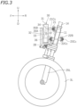
- FIG. 3 is a left side view of a part of the leaning vehicle 1.
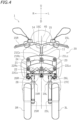
- FIG. 4 is a front view of a part of the leaning vehicle 1.
- FIG. 5 is a plan view of a part of the leaning vehicle 1.
- front, rear, left, right, up and down refer to these directions as seen from a virtual rider seated on a seat 5 while the leaning vehicle 1 is standing upright (standing upright as used herein refers to a state where a vehicle body frame 10 to be described below is standing upright) on a horizontal surface with no rider and no load thereon, unless specified otherwise.
- the vehicle up-down direction coincides with the vertical direction.
- the vehicle front-rear direction is orthogonal to the vehicle up-down direction.
- the vehicle left-right direction is orthogonal to the vehicle front-rear direction and the vehicle up-down direction.
- the leaning vehicle 1 includes the vehicle body frame 10 , a link mechanism 20 , a left front wheel 3L , a right front wheel 3R (see FIG. 4 ), a rear wheel 4 , a power unit 2 , the seat 5 and a storage box 16 .
- the leaning vehicle 1 is a three-wheel vehicle with two front wheels 3L , 3R and one rear wheel 4 .
- the vehicle body frame 10 includes a head pipe 11 , a down frame 12 extending rearward and downward from the head pipe 11 , and a seat frame 13 extending rearward from the down frame 12 .
- the seat 5 is supported by the vehicle body frame 10.
- the seat 5 is supported by the seat frame 13.
- the storage box 16 is arranged downward of the seat 5 , and supported by the seat frame 13.
- a steering shaft 14 is rotatably supported by the head pipe 11.
- a steering handle 15 is fixed to the steering shaft 14.
- the leaning vehicle 1 is a scooter.
- the leaning vehicle 1 includes a low footrest 7.
- the footrest 7 is supported by the vehicle body frame 10.
- the footrest 7 is supported by the down frame 12 (see FIG. 2 ).
- the footrest 7 is arranged downward of the seat 5.
- the footrest 7 is a platform for supporting the feet of the rider seated on the seat 5.
- the link mechanism 20 is a parallelogram link-type link mechanism.
- the link mechanism 20 is arranged upward relative to the left front wheel 3L and the right front wheel 3R.
- the link mechanism 20 includes an upper arm 21 , a lower arm 22 , a left arm 23 and a right arm 24.
- the upper arm 21 and the lower arm 22 extend leftward and rightward.
- the upper arm 21 and the lower arm 22 are examples of link members extending leftward and rightward of the vehicle body frame 10.
- the lower arm 22 is arranged downward of the upper arm 21.
- the upper arm 21 and the lower arm 22 are arranged forward of the head pipe 11 (see FIG. 2 ).
- the upper arm 21 is rotatably linked to the head pipe 11 by a first central link shaft 21Cc extending in the vehicle front-rear direction.
- the lower arm 22 is rotatably linked to the head pipe 11 by a second central link shaft 22Cc extending in the vehicle front-rear direction.
- another lower arm 22B is arranged rearward of the head pipe 11.
- the lower arm 22B extends leftward and rightward.
- the lower arm 22B is arranged downward of the upper arm 21.
- the lower arm 22B is rotatably linked to the head pipe 11 by a third central link shaft 23Cc (see FIG. 3 ) extending in the vehicle front-rear direction.
- another upper arm (not shown) may be arranged rearward of the head pipe 11 , and this upper arm may be rotatably linked to the head pipe 11 by another central link shaft (not shown) extending in the vehicle front-rear direction.
- the other upper arm and the other lower arm 22B arranged rearward of the head pipe 11 are optional.
- the left arm 23 and the right arm 24 extend upward and downward.
- the left arm 23 is arranged leftward of the head pipe 11 and the right arm 24 is arranged rightward of the head pipe 11.
- the right arm 24 is arranged rightward of the left arm 23.
- the left arm 23 and the right arm 24 are arranged rearward of the upper arm 21 and the lower arm 22.
- the left arm 23 and the right arm 24 are arranged forward of the lower arm 22B.
- the left arm 23 and the right arm 24 are rotatably linked to the upper arm 21 , the lower arm 22 and the lower arm 22B.
- the upper end portion of the left arm 23 is rotatably linked to the left end portion of the upper arm 21 by a first left link shaft 21Lc extending in the vehicle front-rear direction.
- the lower end portion of the left arm 23 is rotatably linked to the left end portion of the lower arm 22 by a second left link shaft 22Lc extending in the vehicle front-rear direction.
- the lower end of the left arm 23 is rotatably linked to the left end portion of the lower arm 22B by a third left link shaft (not shown) extending in the vehicle front-rear direction.
- the upper end portion of the right arm 24 is rotatably linked to the right end portion of the upper arm 21 by the first right link shaft 21 Rc extending in the vehicle front-rear direction.
- the lower end portion of the right arm 24 is rotatably linked to the right end portion of the lower arm 22 by the second right link shaft 22Rc extending in the vehicle front-rear direction.
- the lower end portion of the right arm 24 is rotatably linked to the right end portion of the lower arm 22B by a third right link shaft (not shown) extending in the vehicle front-rear direction.
- the leaning vehicle 1 includes, as front suspensions, a left suspension 25L and a right suspension 25R.
- the left suspension 25L and the right suspension 25R are telescopic suspensions.
- the upper end portion of the left suspension 25L and the upper end portion of the right suspension 25R are connected to the link mechanism 20.
- the lower end portion of the left suspension 25L is connected to the left front wheel 3L
- the lower portion of the right suspension 25R is connected to the right front wheel 3R.
- the upper end portion of the left suspension 25L is connected to the lower end portion of the left arm 23 via a left bracket 26L.
- the upper end portion of the left suspension 25L is connected to the left arm 23 so as to be rotatable in the left-right direction of the vehicle body frame 10.
- the upper end portion of the right suspension 25R is connected to the lower end portion of the right arm 24 via a right bracket 26R.
- the upper end portion of the right suspension 25R is connected to the right arm 24 so as to be rotatable in the left-right direction of the vehicle body frame 10.
- the left suspension 25L , the left bracket 26L and the left arm 23 together form a left wheel support member 19L that supports the left front wheel 3L.
- the right suspension 25R , the right bracket 26R and the right arm 24 together form a right wheel support member 19R that supports the right front wheel 3R.
- a center plate 27C is fixed to the lower end portion of the steering shaft 14. As shown in FIG. 5 , the center plate 27C extends forward from the steering shaft 14. A left plate 27L is fixed to the left bracket 26L. A right plate 27R is fixed to the right bracket 26R. The left plate 27L , the center plate 27C and the right plate 27R are linked to a tie rod 28 so as to be rotatable left and right.
- the steering shaft 14 is linked to the left arm 23 and the right arm 24 via the center plate 27C , the tie rod 28 , the left plate 27L and the right plate 27R.
- the leaning vehicle 1 includes a roll angle control device 30 that controls the roll angle.
- the roll angle as used herein is the tilt angle ⁇ (see FIG. 6 ) of the vehicle body frame 10 from the vertical line.
- the roll angle ⁇ is equal to the angle between the axis of the head pipe 11 and the vertical line as viewed in the vehicle front view.
- the roll angle control device 30 controls the roll angle of the vehicle body frame 10 by adjusting the rotation of the upper arm 21 and the lower arm 22 relative to the vehicle body frame 10.
- the roll angle control device 30 is configured to apply a torque to at least one of the upper arm 21 and the lower arm 22.
- the roll angle control device 30 is connected to at least one of the upper arm 21 and lower arm 22 , and to the vehicle body frame 10. In the present embodiment, the roll angle control device 30 is connected to the upper arm 21 and the head pipe 11. Note however that there is no particular limitation thereto, and the roll angle control device 30 may be connected to the lower arm 22 and the head pipe 11.
- the roll angle control device 30 includes a case 31 , a lean actuator 33 , a gear 35A and a gear 35B arranged inside the case 31 , and an actuator control device 36 arranged inside the case 31.
- the case 31 is supported by a support member 32 fixed to the head pipe 11.
- the lean actuator 33 is a power source that applies a torque around the first central link shaft 21Cc to the vehicle body frame 10.
- the lean actuator 33 may apply a torque directly or indirectly to the vehicle body frame 10.
- the lean actuator 33 applies a leftward or rightward torque to the upper arm 21 , thereby indirectly applying a rightward or leftward torque to the vehicle body frame 10.
- the lean actuator 33 is an electric motor. Note however that the lean actuator 33 is not limited to an electric motor as long as the lean actuator 33 can generate power.
- the lean actuator 33 is connected to the gear 35A , and the gear 35A is meshed with the gear 35B.
- the gear 35A and the gear 35B together form a decelerator.
- the gear 35B is fixed to an output shaft 34.
- the output shaft 34 is a rotating shaft driven by the lean actuator 33 and is connected to the upper arm 21.
- the torque of the lean actuator 33 is transmitted to the upper arm 21 via the gear 35A , the gear 35B and the output shaft 34.
- a torque around the first central link shaft 21Cc (see FIG. 4 ) is applied to the upper arm 21.
- the upper arm 21 is linked to the vehicle body frame 10 so as to be rotatable around the first central link shaft 21Cc , when a torque around the first central link shaft 21Cc is applied to the upper arm 21 , a torque around the first central link shaft 21 Cc is generated in the vehicle body frame 10.
- the leaning vehicle 1 includes an IMU (not shown).
- the actuator control device 36 is communicatively connected to the IMU via a wire harness (not shown).
- the actuator control device 36 is configured to receive a signal from the IMU and control the lean actuator 33.
- a power unit 2 is pivotally supported on the vehicle body frame 10.
- the power unit 2 is connected to the rear wheel 4 so that power can be transmitted therebetween.
- the power unit 2 generates driving force for traveling.
- the power unit 2 provides power to the rear wheel 4 .
- the power unit 2 may include an internal combustion engine or may include an electric motor.
- the power unit 2 includes an internal combustion engine (hereinafter referred to as an "engine").
- the leaning vehicle 1 includes left and right rear suspensions 50.
- the left rear suspension 50 is arranged leftward of the rear wheel 4 and the right rear suspension 50 is arranged rightward of the rear wheel 4.
- Each rear suspension 50 includes an upper support portion 51 pivotably supported on the vehicle body frame 10 and a lower support portion 52 pivotably supported on the rear wheel 4.
- the upper support portion 51 is pivotably supported on the seat frame 13 via a bracket 13B.
- the lower support portion 52 is pivotably supported on a bracket 4B mounted on the axle of the rear wheel 4.
- the leaning vehicle 1 includes a power source 41 that supplies power, a main switch 40 that is operated by the rider, an operation switch 43 , and electrical components including an actuator control device 36.
- the leaning vehicle 1 includes a battery and a generator that generates electricity from the power of a power unit 2.
- the power source 41 is composed of the battery and the generator.
- the main switch 40 is a switch that switches ON/OFF the power supply from the power source 41 to electrical components.
- the main switch 40 or the operation switch 43 may be mounted on the steering handle 15 , for example.
- the main switch 40 or the operation switch 43 may be arranged rightward of a left grip 15L or arranged leftward of a right grip 15R.
- the actuator control device 36 controls the lean actuator 33 to automatically keep the vehicle body frame 10 standing upright.
- the control by which the actuator control device 36 controls the lean actuator 33 keep the vehicle body frame 10 standing by itself will hereinafter be referred to as standing assist.
- the vehicle body frame 10 is subjected to a leftward force. As it is, the vehicle body frame 10 will lean leftward.
- the actuator control device 36 detects the tilt of the vehicle body frame 10 based on the signal from the IMU.
- the actuator control device 36 controls the lean actuator 33 to eliminate the tilt. Specifically, the actuator control device 36 controls the lean actuator 33 so that the roll angle of the vehicle body frame 10 becomes zero.
- the actuator control device 36 controls the lean actuator 33 so as to apply a rightward torque to the vehicle body frame 10.
- the actuator control device 36 controls the lean actuator 33 so as to apply a leftward torque to the vehicle body frame 10.
- the operation switch 43 is a switch that turns ON/OFF the standing assist.
- the vehicle body frame 10 is kept standing by itself even if the rider does not put their feet on the ground.
- the vehicle body frame 10 is kept standing by itself even if the rider places both feet on a footrest 7. If the operation switch 43 is turned ON while the main switch 40 is ON, the standing assist is started, and if the operation switch 43 is turned OFF while the main switch 40 is ON, the standing assist is terminated.
- the actuator control device 36 is a computer. As shown in FIG. 8 , the actuator control device 36 executes a computer program and as a result functions as a standing assist control section 37 , a standing assist continuation section 38 and a notification control section 39.
- the standing assist control section 37 controls the lean actuator 33 so that the vehicle body frame 10 stands by itself when the operation switch 43 is ON.
- the standing assist continuation section 38 continues to control the lean actuator 33 until a predetermined amount of time (hereinafter referred to as the continuation time) elapses, and when the continuation time elapses, the control of the lean actuator 33 is terminated.
- the continuation time a predetermined amount of time (hereinafter referred to as the continuation time) elapses, and when the continuation time elapses, the control of the lean actuator 33 is terminated.
- the continuation time a predetermined amount of time
- the continuation time elapses
- the standing assist continuation section 38 may keep the output torque T of the lean actuator 33 constant until the continuation time t0 elapses after the main switch 40 is turned OFF, as indicated by a solid line P1 in FIG. 9 .
- the symbol t in FIG. 9 represents the elapsed time from when the main switch 40 is turned OFF
- the symbol T represents the output torque of the lean actuator 33.
- the standing assist continuation section 38 may gradually decrease the output torque T of the lean actuator 33 until the continuation time t0 elapses from when the main switch 40 is turned OFF, as indicated by a broken line P2 , a single-dot chain line P3 or a double-dot chain line P4.
- the leaning vehicle 1 includes a speaker 45 and a display device 46.
- the notification control section 39 gives a notification to the rider until the continuation time elapses.
- the notification control section 39 outputs a sound from the speaker 45 and/or displays a predetermined image on the display device 46 until the continuation time elapses.
- the rider can easily know that the standing assist is continuing after the main switch 40 is turned OFF.
- the notification control section 39 , the speaker 45 and the display device 46 together form a notification device 49.
- the leaning vehicle 1 is configured as described above. With the leaning vehicle 1 according to the present embodiment, the following effects can be obtained.
- the leaning vehicle 1 is capable of providing standing assist, and the leaning vehicle 1 can stand by itself even if the rider does not support the leaning vehicle 1 with their feet on the ground.
- the main switch 40 is turned OFF while the rider places their feet on the footrest 7 , if the power supply to the actuator control device 36 and the lean actuator 33 is immediately stopped, the torque of the lean actuator 33 disappears suddenly and the vehicle body frame 10 tilts suddenly. In such a case, the rider must quickly put their feet on the ground to support the vehicle body frame 10. This places a burden on the rider.
- the leaning vehicle 1 when the rider turns OFF the main switch 40 during execution of the standing assist, the torque of the lean actuator 33 does not disappear immediately, but remains until a predetermined continuation time elapses. Therefore, the rider does not need to support the vehicle body frame 10 from the moment the rider turns OFF the main switch 40. Between the time when the main switch 40 is turned OFF and the time when the torque of the lean actuator 33 disappears, there is a time margin for preparing to support the vehicle body frame 10. Therefore, with the leaning vehicle 1 according to the present embodiment, the burden on the rider after the main switch 40 is turned OFF can be reduced.
- the torque of the lean actuator 33 disappears after the continuation time elapses after the main switch 40 is turned OFF. Thereafter, the rider can turn the leaning vehicle 1 while pushing the leaning vehicle 1. Thus, the rider can easily move the leaning vehicle 1 to a parking location, etc., without having to perform a complicated operation.
- the standing assist continuation section 38 of the actuator control device 36 may gradually decrease the torque of the lean actuator 33 until the continuation time elapses when the main switch 40 is turned OFF during execution of the standing assist (see lines P2 , P3 and P4 in FIG. 9 ).
- the torque of the lean actuator 33 it is possible to prevent the torque of the lean actuator 33 from disappearing rapidly before the continuation time elapses from when the rider turns OFF the main switch 40 .
- This can prevent the load of the vehicle body frame 10 from being suddenly placed against the rider after the main switch 40 is turned OFF, thus reducing the burden on the rider.
- the notification device 49 is provided for giving a notification to the rider until the continuation time elapses when the main switch 40 is turned OFF during execution of the standing assist.
- the notification device 49 notifies the rider by means of a sound from the speaker 45 or an image by the display device 46.
- the rider can easily know that the torque of the lean actuator 33 remains and that the torque of the lean actuator 33 will eventually disappear.
- the rider can prepare for the disappearance of the torque of the lean actuator 33.
- the leaning vehicle 1 in the embodiment described above is a scooter.
- the vehicle form of the leaning vehicle is not limited to a scooter.
- the notification device 49 may include an additional device for giving a notification to the rider, other than the speaker 45 for giving a notification by means of a sound and the display device 46 for giving a notification by means of an image.
- the notification device 49 may be optional.
Landscapes
- Engineering & Computer Science (AREA)
- Mechanical Engineering (AREA)
- Automatic Cycles, And Cycles In General (AREA)
- Vehicle Body Suspensions (AREA)
Abstract
Description
- The present invention relates to a leaning vehicle having a left wheel and a right wheel, wherein the leaning vehicle tilts when turning left and right.
- For example, as disclosed in
JP 2018 - 149 962 A - The leaning vehicle includes an actuator that applies a torque around an axis extending in the vehicle front-rear direction to the vehicle body frame. According to such a leaning vehicle, the actuator can be controlled to keep the vehicle body frame standing by itself. Hereinafter, keeping the vehicle body frame standing by itself by using the actuator will be referred to as standing assist. By providing standing assist when the vehicle is stopped, the vehicle body frame can be kept from leaning even if the rider does not put their feet on the ground.
- With a conventional leaning vehicle, turning OFF the main switch immediately stops the power supply to the actuator. The torque generated by the actuator to keep the vehicle body frame standing by itself disappears upon turning OFF the main switch. Therefore, the rider needs to support the vehicle body frame by themselves immediately upon turning OFF the main switch.
- One may consider continuing the control of the actuator even after the main switch is turned OFF in order to reduce the burden on the rider when the main switch is turned OFF. However, the rider may push the leaning vehicle to a parking location, for example, after the main switch is turned OFF. Then, the vehicle body frame may be tilted to turn the leaning vehicle. In this case, if the actuator continues to generate torque, it becomes difficult to turn the leaning vehicle while pushing it, and it is no longer possible to smoothly move the leaning vehicle.
- The present invention has been made in view of the above, and an object thereof is to provide a leaning vehicle, with which standing assist can be provided, there is little burden on the rider after the main switch is turned OFF, and it is easy for the rider to move the leaning vehicle. According to the present invention said object is solved by a leaning vehicle having the features of the
independent claim 1. Preferred embodiments are laid down in the dependent claims. - A leaning vehicle disclosed herein includes: a vehicle body frame including a head pipe; a left wheel arranged leftward relative to the head pipe; a right wheel arranged rightward relative to the head pipe; a left wheel support member that is configured to support the left wheel; a right wheel support member that is arranged rightward of the left wheel support member and is configured to support the right wheel; a link member extending leftward and rightward of the vehicle body frame; a central link shaft extending in a vehicle front-rear direction that rotatably links the vehicle body frame to the link member; a left link shaft extending in the vehicle front-rear direction that rotatably links the left wheel support member to the link member; a right link shaft extending in the vehicle front-rear direction that rotatably links the right wheel support member to the link member; an actuator that is configured to apply a torque around the central link shaft to the vehicle body frame; a control device that is configured to control the actuator; and a main switch that is operated by a rider. The control device includes: a standing assist control section that is configured to execute standing assist for keeping the vehicle body frame standing by itself by controlling the actuator; and a standing assist continuation section that is configured to continue the control of the actuator until a predetermined amount of time elapses when the main switch is turned OFF during execution of the standing assist, and that is configured to terminate the control of the actuator when the predetermined amount of time elapses.
- With the leaning vehicle described above, when the rider turns OFF the main switch during execution of the standing assist, the torque of the actuator does not disappear immediately but remains until the predetermined amount of time elapses. Therefore, the rider does not need to support the vehicle body frame from the moment the main switch is turned OFF. Thus, it is possible to reduce the burden on the rider. With the leaning vehicle described above, since the torque of the actuator disappears when the predetermined amount of time elapses after the main switch is turned OFF, the rider can turn the leaning vehicle while pushing the leaning vehicle. Thus, the rider can easily move the leaning vehicle to a parking location, etc., after the predetermined amount of time elapses.
- The standing assist continuation section may be configured to gradually decrease the torque output by the actuator until the predetermined amount of time elapses when the main switch is turned OFF during execution of the standing assist.
- Thus, it is possible to prevent the output torque of the actuator from disappearing rapidly before the predetermined amount of time elapses from when the rider turns OFF the main switch. This can prevent the load of the vehicle body frame from being suddenly placed against the rider after the main switch is turned OFF, thus reducing the burden on the rider.
- The leaning vehicle may include a notification device that is configured to give a notification to the rider until the predetermined amount of time elapses when the main switch is turned OFF during execution of the standing assist.
- Thus, the rider can easily know that the torque of the actuator remains after the main switch is turned OFF. The rider can prepare for the disappearance of the torque of the actuator.
- While there is no particular limitation on the predetermined amount of time, it may be 0.3 to 1 second, for example.
- The leaning vehicle may include: a steering shaft supported by the head pipe; and a steering handle fixed to the steering shaft. The left wheel and the right wheel may be a left front wheel and a right front wheel, respectively, arranged forward of the steering handle.
- The leaning vehicle may include: a seat supported by the vehicle body frame; and a footrest supported by the vehicle body frame, arranged downward of the seat, and supporting feet of the rider seated on the seat.
- With the present invention, it is possible to provide a leaning vehicle, with which standing assist can be provided, there is little burden on the rider after the main switch is turned OFF, and it is easy for the rider to move the leaning vehicle.
-
-
FIG. 1 is a left side view of a leaning vehicle according to one embodiment. -
FIG. 2 is a left side view of a part of the leaning vehicle. -
FIG. 3 is a left side view of a part of the leaning vehicle. -
FIG. 4 is a front view of a part of the leaning vehicle. -
FIG. 5 is a plan view of a part of the leaning vehicle. -
FIG. 6 is a front view of a part of the leaning vehicle with the vehicle body frame tilted leftward. -
FIG. 7 is an electric circuit diagram of a part of the leaning vehicle. -
FIG. 8 is a block diagram of a control system of the leaning vehicle. -
FIG. 9 is a graph showing the relationship between the time elapsed after the main switch is turned OFF and the output torque of the lean actuator. - One embodiment of a leaning vehicle will now be described with reference to the drawings.
FIG. 1 is a left side view of aleaning vehicle 1 according to the present embodiment.FIG. 2 is a left side view of a part of theleaning vehicle 1.FIG. 3 is a left side view of a part of theleaning vehicle 1.FIG. 4 is a front view of a part of theleaning vehicle 1.FIG. 5 is a plan view of a part of the leaningvehicle 1. - The terms front, rear, left, right, up and down, as used in the description below, refer to these directions as seen from a virtual rider seated on a
seat 5 while theleaning vehicle 1 is standing upright (standing upright as used herein refers to a state where avehicle body frame 10 to be described below is standing upright) on a horizontal surface with no rider and no load thereon, unless specified otherwise. The designations F, B, L, R, U and D, as used in the figures, refer to front, rear, left, right, up and down, respectively. The vehicle up-down direction coincides with the vertical direction. The vehicle front-rear direction is orthogonal to the vehicle up-down direction. The vehicle left-right direction is orthogonal to the vehicle front-rear direction and the vehicle up-down direction. - As shown in
FIG. 1 andFIG. 2 , theleaning vehicle 1 includes thevehicle body frame 10, alink mechanism 20, a leftfront wheel 3L, a rightfront wheel 3R (seeFIG. 4 ), arear wheel 4, apower unit 2, theseat 5 and astorage box 16. The leaningvehicle 1 is a three-wheel vehicle with twofront wheels rear wheel 4. - As shown in
FIG. 2 , thevehicle body frame 10 includes ahead pipe 11, adown frame 12 extending rearward and downward from thehead pipe 11, and aseat frame 13 extending rearward from thedown frame 12. Theseat 5 is supported by thevehicle body frame 10. Herein, theseat 5 is supported by theseat frame 13. Thestorage box 16 is arranged downward of theseat 5, and supported by theseat frame 13. As shown inFIG. 4 , asteering shaft 14 is rotatably supported by thehead pipe 11. Asteering handle 15 is fixed to thesteering shaft 14. - As shown in
FIG. 1 , the leaningvehicle 1 according to the present embodiment is a scooter. The leaningvehicle 1 includes a low footrest 7. The footrest 7 is supported by thevehicle body frame 10. Herein, the footrest 7 is supported by the down frame 12 (seeFIG. 2 ). The footrest 7 is arranged downward of theseat 5. The footrest 7 is a platform for supporting the feet of the rider seated on theseat 5. - As shown in
FIG. 4 , thelink mechanism 20 is a parallelogram link-type link mechanism. Thelink mechanism 20 is arranged upward relative to theleft front wheel 3L and theright front wheel 3R. Thelink mechanism 20 includes anupper arm 21, alower arm 22, aleft arm 23 and aright arm 24. - The
upper arm 21 and thelower arm 22 extend leftward and rightward. Theupper arm 21 and thelower arm 22 are examples of link members extending leftward and rightward of thevehicle body frame 10. Thelower arm 22 is arranged downward of theupper arm 21. Theupper arm 21 and thelower arm 22 are arranged forward of the head pipe 11 (seeFIG. 2 ). Theupper arm 21 is rotatably linked to thehead pipe 11 by a first central link shaft 21Cc extending in the vehicle front-rear direction. Thelower arm 22 is rotatably linked to thehead pipe 11 by a second central link shaft 22Cc extending in the vehicle front-rear direction. - In the present embodiment, as shown in
FIG. 2 , anotherlower arm 22B is arranged rearward of thehead pipe 11. Thelower arm 22B extends leftward and rightward. Thelower arm 22B is arranged downward of theupper arm 21. Thelower arm 22B is rotatably linked to thehead pipe 11 by a third central link shaft 23Cc (seeFIG. 3 ) extending in the vehicle front-rear direction. Note that another upper arm (not shown) may be arranged rearward of thehead pipe 11, and this upper arm may be rotatably linked to thehead pipe 11 by another central link shaft (not shown) extending in the vehicle front-rear direction. Note however that the other upper arm and the otherlower arm 22B arranged rearward of thehead pipe 11 are optional. - As shown in
FIG. 4 , theleft arm 23 and theright arm 24 extend upward and downward. Theleft arm 23 is arranged leftward of thehead pipe 11 and theright arm 24 is arranged rightward of thehead pipe 11. Theright arm 24 is arranged rightward of theleft arm 23. Theleft arm 23 and theright arm 24 are arranged rearward of theupper arm 21 and thelower arm 22. Theleft arm 23 and theright arm 24 are arranged forward of thelower arm 22B. Theleft arm 23 and theright arm 24 are rotatably linked to theupper arm 21, thelower arm 22 and thelower arm 22B. - Specifically, the upper end portion of the
left arm 23 is rotatably linked to the left end portion of theupper arm 21 by a first left link shaft 21Lc extending in the vehicle front-rear direction. The lower end portion of theleft arm 23 is rotatably linked to the left end portion of thelower arm 22 by a second left link shaft 22Lc extending in the vehicle front-rear direction. The lower end of theleft arm 23 is rotatably linked to the left end portion of thelower arm 22B by a third left link shaft (not shown) extending in the vehicle front-rear direction. The upper end portion of theright arm 24 is rotatably linked to the right end portion of theupper arm 21 by the firstright link shaft 21 Rc extending in the vehicle front-rear direction. The lower end portion of theright arm 24 is rotatably linked to the right end portion of thelower arm 22 by the second right link shaft 22Rc extending in the vehicle front-rear direction. The lower end portion of theright arm 24 is rotatably linked to the right end portion of thelower arm 22B by a third right link shaft (not shown) extending in the vehicle front-rear direction. - The leaning
vehicle 1 includes, as front suspensions, aleft suspension 25L and aright suspension 25R. In the present embodiment, theleft suspension 25L and theright suspension 25R are telescopic suspensions. The upper end portion of theleft suspension 25L and the upper end portion of theright suspension 25R are connected to thelink mechanism 20. The lower end portion of theleft suspension 25L is connected to theleft front wheel 3L, and the lower portion of theright suspension 25R is connected to theright front wheel 3R. Specifically, the upper end portion of theleft suspension 25L is connected to the lower end portion of theleft arm 23 via aleft bracket 26L. The upper end portion of theleft suspension 25L is connected to theleft arm 23 so as to be rotatable in the left-right direction of thevehicle body frame 10. The upper end portion of theright suspension 25R is connected to the lower end portion of theright arm 24 via aright bracket 26R. The upper end portion of theright suspension 25R is connected to theright arm 24 so as to be rotatable in the left-right direction of thevehicle body frame 10. - The
left suspension 25L, theleft bracket 26L and theleft arm 23 together form a leftwheel support member 19L that supports theleft front wheel 3L. Theright suspension 25R, theright bracket 26R and theright arm 24 together form a rightwheel support member 19R that supports theright front wheel 3R. - A
center plate 27C is fixed to the lower end portion of the steeringshaft 14. As shown inFIG. 5 , thecenter plate 27C extends forward from the steeringshaft 14. Aleft plate 27L is fixed to theleft bracket 26L. Aright plate 27R is fixed to theright bracket 26R. Theleft plate 27L, thecenter plate 27C and theright plate 27R are linked to atie rod 28 so as to be rotatable left and right. The steeringshaft 14 is linked to theleft arm 23 and theright arm 24 via thecenter plate 27C, thetie rod 28, theleft plate 27L and theright plate 27R. - As shown in
FIG. 3 , the leaningvehicle 1 includes a rollangle control device 30 that controls the roll angle. Note that in the figures other thanFIG. 3 , the rollangle control device 30 is not shown. The roll angle as used herein is the tilt angle θ (seeFIG. 6 ) of thevehicle body frame 10 from the vertical line. Note that in the present embodiment, the roll angle θ is equal to the angle between the axis of thehead pipe 11 and the vertical line as viewed in the vehicle front view. The rollangle control device 30 controls the roll angle of thevehicle body frame 10 by adjusting the rotation of theupper arm 21 and thelower arm 22 relative to thevehicle body frame 10. The rollangle control device 30 is configured to apply a torque to at least one of theupper arm 21 and thelower arm 22. The rollangle control device 30 is connected to at least one of theupper arm 21 andlower arm 22, and to thevehicle body frame 10. In the present embodiment, the rollangle control device 30 is connected to theupper arm 21 and thehead pipe 11. Note however that there is no particular limitation thereto, and the rollangle control device 30 may be connected to thelower arm 22 and thehead pipe 11. - The roll
angle control device 30 includes acase 31, alean actuator 33, agear 35A and agear 35B arranged inside thecase 31, and anactuator control device 36 arranged inside thecase 31. Thecase 31 is supported by asupport member 32 fixed to thehead pipe 11. - The
lean actuator 33 is a power source that applies a torque around the first central link shaft 21Cc to thevehicle body frame 10. Thelean actuator 33 may apply a torque directly or indirectly to thevehicle body frame 10. In the present embodiment, thelean actuator 33 applies a leftward or rightward torque to theupper arm 21, thereby indirectly applying a rightward or leftward torque to thevehicle body frame 10. In the present embodiment, thelean actuator 33 is an electric motor. Note however that thelean actuator 33 is not limited to an electric motor as long as thelean actuator 33 can generate power. - The
lean actuator 33 is connected to thegear 35A, and thegear 35A is meshed with thegear 35B. Thegear 35A and thegear 35B together form a decelerator. Thegear 35B is fixed to anoutput shaft 34. Theoutput shaft 34 is a rotating shaft driven by thelean actuator 33 and is connected to theupper arm 21. The torque of thelean actuator 33 is transmitted to theupper arm 21 via thegear 35A, thegear 35B and theoutput shaft 34. When thelean actuator 33 is driven, a torque around the first central link shaft 21Cc (seeFIG. 4 ) is applied to theupper arm 21. Since theupper arm 21 is linked to thevehicle body frame 10 so as to be rotatable around the first central link shaft 21Cc, when a torque around the first central link shaft 21Cc is applied to theupper arm 21, a torque around the firstcentral link shaft 21 Cc is generated in thevehicle body frame 10. - The leaning
vehicle 1 includes an IMU (not shown). Theactuator control device 36 is communicatively connected to the IMU via a wire harness (not shown). Theactuator control device 36 is configured to receive a signal from the IMU and control thelean actuator 33. - As shown in
FIG. 2 , apower unit 2 is pivotally supported on thevehicle body frame 10. Thepower unit 2 is connected to therear wheel 4 so that power can be transmitted therebetween. Thepower unit 2 generates driving force for traveling. Thepower unit 2 provides power to therear wheel 4. Thepower unit 2 may include an internal combustion engine or may include an electric motor. In the present embodiment, thepower unit 2 includes an internal combustion engine (hereinafter referred to as an "engine"). - The leaning
vehicle 1 includes left and rightrear suspensions 50. The leftrear suspension 50 is arranged leftward of therear wheel 4 and the rightrear suspension 50 is arranged rightward of therear wheel 4. Eachrear suspension 50 includes anupper support portion 51 pivotably supported on thevehicle body frame 10 and alower support portion 52 pivotably supported on therear wheel 4. Herein, theupper support portion 51 is pivotably supported on theseat frame 13 via abracket 13B. Thelower support portion 52 is pivotably supported on abracket 4B mounted on the axle of therear wheel 4. - As shown in
FIG. 7 , the leaningvehicle 1 includes apower source 41 that supplies power, amain switch 40 that is operated by the rider, anoperation switch 43, and electrical components including anactuator control device 36. Although not shown in the figures, the leaningvehicle 1 includes a battery and a generator that generates electricity from the power of apower unit 2. Thepower source 41 is composed of the battery and the generator. Themain switch 40 is a switch that switches ON/OFF the power supply from thepower source 41 to electrical components. There is no particular limitation on the locations of themain switch 40 and theoperation switch 43. Themain switch 40 or theoperation switch 43 may be mounted on thesteering handle 15, for example. Themain switch 40 or theoperation switch 43 may be arranged rightward of aleft grip 15L or arranged leftward of aright grip 15R. - With the leaning
vehicle 1, theactuator control device 36 controls thelean actuator 33 to automatically keep thevehicle body frame 10 standing upright. The control by which theactuator control device 36 controls thelean actuator 33 keep thevehicle body frame 10 standing by itself will hereinafter be referred to as standing assist. - For example, when the rider seated on the
seat 5 applies their weight to the left, thevehicle body frame 10 is subjected to a leftward force. As it is, thevehicle body frame 10 will lean leftward. Theactuator control device 36 detects the tilt of thevehicle body frame 10 based on the signal from the IMU. When theactuator control device 36 detects the tilt of thevehicle body frame 10, theactuator control device 36 controls thelean actuator 33 to eliminate the tilt. Specifically, theactuator control device 36 controls thelean actuator 33 so that the roll angle of thevehicle body frame 10 becomes zero. When thevehicle body frame 10 leans leftward, theactuator control device 36 controls thelean actuator 33 so as to apply a rightward torque to thevehicle body frame 10. When thevehicle body frame 10 leans rightward, theactuator control device 36 controls thelean actuator 33 so as to apply a leftward torque to thevehicle body frame 10. - The
operation switch 43 is a switch that turns ON/OFF the standing assist. During execution of the standing assist, thevehicle body frame 10 is kept standing by itself even if the rider does not put their feet on the ground. During execution of the standing assist, thevehicle body frame 10 is kept standing by itself even if the rider places both feet on a footrest 7. If theoperation switch 43 is turned ON while themain switch 40 is ON, the standing assist is started, and if theoperation switch 43 is turned OFF while themain switch 40 is ON, the standing assist is terminated. - The
actuator control device 36 is a computer. As shown inFIG. 8 , theactuator control device 36 executes a computer program and as a result functions as a standingassist control section 37, a standingassist continuation section 38 and anotification control section 39. - The standing
assist control section 37 controls thelean actuator 33 so that thevehicle body frame 10 stands by itself when theoperation switch 43 is ON. - When the
main switch 40 is turned OFF during execution of the standing assist, the standing assistcontinuation section 38 continues to control thelean actuator 33 until a predetermined amount of time (hereinafter referred to as the continuation time) elapses, and when the continuation time elapses, the control of thelean actuator 33 is terminated. In other words, when themain switch 40 is turned OFF during execution of the standing assist, the standing assistcontinuation section 38 continues the standing assist until the continuation time elapses and terminates the standing assist when the continuation time elapses. While there is no particular limitation on the continuation time, it may be 0.3 to 1 second, for example. - There is no particular limitation on the method of controlling the
lean actuator 33 by the standing assistcontinuation section 38. For example, the standing assistcontinuation section 38 may keep the output torque T of thelean actuator 33 constant until the continuation time t0 elapses after themain switch 40 is turned OFF, as indicated by a solid line P1 inFIG. 9 . Note that the symbol t inFIG. 9 represents the elapsed time from when themain switch 40 is turned OFF, and the symbol T represents the output torque of thelean actuator 33. The standingassist continuation section 38 may gradually decrease the output torque T of thelean actuator 33 until the continuation time t0 elapses from when themain switch 40 is turned OFF, as indicated by a broken line P2, a single-dot chain line P3 or a double-dot chain line P4. - As shown in
FIG. 8 , the leaningvehicle 1 includes aspeaker 45 and adisplay device 46. When themain switch 40 is turned OFF during execution of the standing assist, thenotification control section 39 gives a notification to the rider until the continuation time elapses. Here, when themain switch 40 is turned OFF during execution of the standing assist, thenotification control section 39 outputs a sound from thespeaker 45 and/or displays a predetermined image on thedisplay device 46 until the continuation time elapses. Thus, the rider can easily know that the standing assist is continuing after themain switch 40 is turned OFF. Note that thenotification control section 39, thespeaker 45 and thedisplay device 46 together form anotification device 49. - The leaning
vehicle 1 is configured as described above. With the leaningvehicle 1 according to the present embodiment, the following effects can be obtained. - The leaning
vehicle 1 is capable of providing standing assist, and the leaningvehicle 1 can stand by itself even if the rider does not support the leaningvehicle 1 with their feet on the ground. Here, when themain switch 40 is turned OFF while the rider places their feet on the footrest 7, if the power supply to theactuator control device 36 and thelean actuator 33 is immediately stopped, the torque of thelean actuator 33 disappears suddenly and thevehicle body frame 10 tilts suddenly. In such a case, the rider must quickly put their feet on the ground to support thevehicle body frame 10. This places a burden on the rider. - In order to reduce the burden on the rider when the
main switch 40 is turned OFF, one may consider continuing the standing assist until theoperation switch 43 is turned OFF even after themain switch 40 is turned OFF. However, the rider may wish to push the leaningvehicle 1 toward a parking location, etc., immediately after turning OFF themain switch 40. In such a case, if the rider forgets to turn OFF theoperation switch 43, the standing assist continues and the rider is not be able to turn thevehicle body frame 10. Without turning OFF theoperation switch 43, the leaningvehicle 1 cannot be easily moved. Therefore, the operation to turn OFF theoperation switch 43 is necessary. However, turning OFF theoperation switch 43 after turning OFF themain switch 40 is a complicated operation, which increases the operational burden on the rider. - In contrast, with the leaning
vehicle 1 according to the present embodiment, when the rider turns OFF themain switch 40 during execution of the standing assist, the torque of thelean actuator 33 does not disappear immediately, but remains until a predetermined continuation time elapses. Therefore, the rider does not need to support thevehicle body frame 10 from the moment the rider turns OFF themain switch 40. Between the time when themain switch 40 is turned OFF and the time when the torque of thelean actuator 33 disappears, there is a time margin for preparing to support thevehicle body frame 10. Therefore, with the leaningvehicle 1 according to the present embodiment, the burden on the rider after themain switch 40 is turned OFF can be reduced. With the leaningvehicle 1 according to the present embodiment, the torque of thelean actuator 33 disappears after the continuation time elapses after themain switch 40 is turned OFF. Thereafter, the rider can turn the leaningvehicle 1 while pushing the leaningvehicle 1. Thus, the rider can easily move the leaningvehicle 1 to a parking location, etc., without having to perform a complicated operation. - As described above, the standing assist
continuation section 38 of theactuator control device 36 may gradually decrease the torque of thelean actuator 33 until the continuation time elapses when themain switch 40 is turned OFF during execution of the standing assist (see lines P2, P3 and P4 inFIG. 9 ). Thus, it is possible to prevent the torque of thelean actuator 33 from disappearing rapidly before the continuation time elapses from when the rider turns OFF themain switch 40. This can prevent the load of thevehicle body frame 10 from being suddenly placed against the rider after themain switch 40 is turned OFF, thus reducing the burden on the rider. - According to the present embodiment, the
notification device 49 is provided for giving a notification to the rider until the continuation time elapses when themain switch 40 is turned OFF during execution of the standing assist. In the present embodiment, thenotification device 49 notifies the rider by means of a sound from thespeaker 45 or an image by thedisplay device 46. Thus, after the main switch is turned OFF, the rider can easily know that the torque of thelean actuator 33 remains and that the torque of thelean actuator 33 will eventually disappear. Thus, the rider can prepare for the disappearance of the torque of thelean actuator 33. - While an embodiment of the leaning vehicle has been described above, the embodiment is merely an example. Various other embodiments are possible.
- The leaning
vehicle 1 in the embodiment described above is a scooter. However, the vehicle form of the leaning vehicle is not limited to a scooter. - One of the
speaker 45 and thedisplay device 46 of thenotification device 49 may be absent. Thenotification device 49 may include an additional device for giving a notification to the rider, other than thespeaker 45 for giving a notification by means of a sound and thedisplay device 46 for giving a notification by means of an image. Thenotification device 49 may be optional. -
- 1
- Leaning vehicle,
- 2
- Power unit,
- 3L
- Left front wheel (left wheel),
- 3R
- Right front wheel (right wheel),
- 4
- Rear wheel,
- 5
- Seat,
- 7
- Footrest,
- 10
- Vehicle body frame,
- 11
- Head pipe,
- 12
- Down frame,
- 14
- Steering shaft,
- 15
- Steering handle,
- 16
- Storage box,
- 19L
- Left wheel support member,
- 19R
- Right wheel support member,
- 20
- Link mechanism,
- 21
- Upper arm (link member),
- 21Cc
- First central link shaft (central link shaft),
- 21Lc
- First left link shaft (left link shaft),
- 21Rc
- First right link shaft (right link shaft),
- 22
- Lower arm (link member),
- 23
- Left arm,
- 24
- Right arm,
- 25L
- Left suspension,
- 25R
- Right suspension,
- 26L
- Left bracket,
- 26R
- Right bracket,
- 27C
- Center plate,
- 27L
- Left plate,
- 27R
- Right plate,
- 28
- Tie rod,
- 30
- Roll angle control device,
- 31
- Case,
- 32
- Support member,
- 33
- Lean actuator (actuator),
- 34
- Output shaft,
- 35A
- First gear,
- 35B
- Second gear,
- 36
- Actuator control device (control device),
- 37
- Standing assist control section,
- 38
- Standing assist continuation section,
- 39
- Notification control section,
- 40
- Main switch,
- 41
- Power soruce,
- 43
- Operation switch,
- 45
- Speaker,
- 46
- Display device,
- 49
- Notification device,
- 50
- Left and right rear suspensions,
- 51
- Upper support portion,
- 52
- Lower support portion.
Claims (6)
- A leaning vehicle (1) comprising:a vehicle body frame (10) including a head pipe (11);a left wheel (3L) arranged leftward relative to the head pipe (11);a right wheel (3R) arranged rightward relative to the head pipe (11);a left wheel support member (19L) that is configured to support the left wheel (3L);a right wheel support member (19R) that is arranged rightward of the left wheel support member (19L) and is configured to support the right wheel (3R);a link member (21) extending leftward and rightward of the vehicle body frame (10);a central link shaft (21Cc) extending in a vehicle front-rear direction that rotatably links the vehicle body frame (10) to the link member (21);a left link shaft (21Lc) extending in the vehicle front-rear direction that rotatably links the left wheel support member (19L) to the link member (21);a right link shaft (21Rc) extending in the vehicle front-rear direction that rotatably links the right wheel support member (19R) to the link member (21);an actuator (33) that is configured to apply a torque around the central link shaft (21Cc) to the vehicle body frame (10);a control device (36) that is configured to control the actuator (33); anda main switch (40) that is operated by a rider,wherein the control device (36) includes:a standing assist control section (37) that is configured to execute standing assist for keeping the vehicle body frame (10) standing by itself by controlling the actuator (33); anda standing assist continuation section (38) that is configured to continue the control of the actuator (33) until a predetermined amount of time elapses when the main switch (40) is turned OFF during execution of the standing assist, and that is configured to terminate the control of the actuator (33) when the predetermined amount of time elapses.
- A leaning vehicle (1) according to claim 1, wherein the standing assist continuation section (38) is configured to gradually decrease the torque output by the actuator (33) until the predetermined amount of time elapses when the main switch (40) is turned OFF during execution of the standing assist.
- A leaning vehicle (1) according to claim 1 or 2, comprising a notification device (49) that is configured to give a notification to the rider until the predetermined amount of time elapses when the main switch (40) is turned OFF during execution of the standing assist.
- A leaning vehicle (1) according to any one of claims 1 to 3, wherein the predetermined amount of time is 0.3 to 1 second.
- A leaning vehicle (1) according to any one of claims 1 to 4, comprising:a steering shaft (14) supported by the head pipe (11); anda steering handle (15) fixed to the steering shaft (14),wherein the left wheel (3L) and the right wheel (3R) are a left front wheel and a right front wheel, respectively, arranged forward of the steering handle (15).
- A leaning vehicle (1) according to any one of claims 1 to 5, comprising:a seat (5) supported by the vehicle body frame (10); anda footrest (7) supported by the vehicle body frame (10), arranged downward of the seat (5), and supporting feet of the rider seated on the seat (5).
Applications Claiming Priority (1)
| Application Number | Priority Date | Filing Date | Title |
|---|---|---|---|
| JP2023034650A JP2024126340A (en) | 2023-03-07 | 2023-03-07 | Lean Vehicle |
Publications (2)
| Publication Number | Publication Date |
|---|---|
| EP4428024A1 true EP4428024A1 (en) | 2024-09-11 |
| EP4428024B1 EP4428024B1 (en) | 2025-04-02 |
Family
ID=89854643
Family Applications (1)
| Application Number | Title | Priority Date | Filing Date |
|---|---|---|---|
| EP24156292.5A Active EP4428024B1 (en) | 2023-03-07 | 2024-02-07 | Leaning vehicle |
Country Status (3)
| Country | Link |
|---|---|
| EP (1) | EP4428024B1 (en) |
| JP (1) | JP2024126340A (en) |
| TW (1) | TWI883679B (en) |
Citations (3)
| Publication number | Priority date | Publication date | Assignee | Title |
|---|---|---|---|---|
| WO2011161856A1 (en) * | 2010-06-25 | 2011-12-29 | 株式会社エクォス・リサーチ | Vehicle |
| JP2018149962A (en) | 2017-03-14 | 2018-09-27 | ヤマハ発動機株式会社 | Lean vehicle and roll angle control method |
| JP2019196108A (en) * | 2018-05-10 | 2019-11-14 | 株式会社デンソーテン | Vehicle control device and vehicle control method |
Family Cites Families (1)
| Publication number | Priority date | Publication date | Assignee | Title |
|---|---|---|---|---|
| MX2015017597A (en) * | 2013-07-01 | 2016-04-15 | Yamaha Motor Co Ltd | Vehicle. |
-
2023
- 2023-03-07 JP JP2023034650A patent/JP2024126340A/en active Pending
- 2023-12-01 TW TW112146827A patent/TWI883679B/en active
-
2024
- 2024-02-07 EP EP24156292.5A patent/EP4428024B1/en active Active
Patent Citations (3)
| Publication number | Priority date | Publication date | Assignee | Title |
|---|---|---|---|---|
| WO2011161856A1 (en) * | 2010-06-25 | 2011-12-29 | 株式会社エクォス・リサーチ | Vehicle |
| JP2018149962A (en) | 2017-03-14 | 2018-09-27 | ヤマハ発動機株式会社 | Lean vehicle and roll angle control method |
| JP2019196108A (en) * | 2018-05-10 | 2019-11-14 | 株式会社デンソーテン | Vehicle control device and vehicle control method |
Also Published As
| Publication number | Publication date |
|---|---|
| JP2024126340A (en) | 2024-09-20 |
| TWI883679B (en) | 2025-05-11 |
| TW202436159A (en) | 2024-09-16 |
| EP4428024B1 (en) | 2025-04-02 |
Similar Documents
| Publication | Publication Date | Title |
|---|---|---|
| US7975786B2 (en) | Electric ground working vehicle | |
| NL2022119B1 (en) | Self-balancing tilting vehicle with an electric tilting member | |
| JP5478739B2 (en) | Regenerative control system for electric vehicles | |
| WO2010061498A1 (en) | Mobile body and control method therefor | |
| EP2331384A1 (en) | Methods and apparatus for moving a vehicle up or down a sloped surface | |
| JPWO2013051195A1 (en) | Electric vehicle | |
| US12043330B2 (en) | Self-balancing tilting vehicle with tilting priority | |
| JP4894589B2 (en) | vehicle | |
| EP4428024B1 (en) | Leaning vehicle | |
| EP4450375A1 (en) | Leaning vehicle | |
| JP7420699B2 (en) | vehicle | |
| JP2002337780A (en) | Foldable body structure for saddle type vehicles | |
| EP4414255A1 (en) | Leaning vehicle | |
| JP7549023B2 (en) | vehicle | |
| JP2000126242A (en) | Electric wheelchair | |
| JP4470580B2 (en) | Electric wheelchair | |
| JP2009131471A (en) | Wheelchair-driven electric unit and wheelchair mounting jig | |
| JP2026044033A (en) | Electric vehicle and its automatic control device | |
| JP3543514B2 (en) | Electric wheelchair | |
| JP2011042200A (en) | Coaxial parallel two-wheel vehicle | |
| JP2023149365A (en) | motorcycle | |
| JP2025119884A (en) | Control device for small electric vehicles | |
| JP2022095323A (en) | Work vehicle | |
| JP2019142343A (en) | Electric drive vehicle | |
| JP2007106246A (en) | Small vehicle |
Legal Events
| Date | Code | Title | Description |
|---|---|---|---|
| PUAI | Public reference made under article 153(3) epc to a published international application that has entered the european phase |
Free format text: ORIGINAL CODE: 0009012 |
|
| STAA | Information on the status of an ep patent application or granted ep patent |
Free format text: STATUS: THE APPLICATION HAS BEEN PUBLISHED |
|
| AK | Designated contracting states |
Kind code of ref document: A1 Designated state(s): AL AT BE BG CH CY CZ DE DK EE ES FI FR GB GR HR HU IE IS IT LI LT LU LV MC ME MK MT NL NO PL PT RO RS SE SI SK SM TR |
|
| STAA | Information on the status of an ep patent application or granted ep patent |
Free format text: STATUS: REQUEST FOR EXAMINATION WAS MADE |
|
| 17P | Request for examination filed |
Effective date: 20240919 |
|
| RBV | Designated contracting states (corrected) |
Designated state(s): AL AT BE BG CH CY CZ DE DK EE ES FI FR GB GR HR HU IE IS IT LI LT LU LV MC ME MK MT NL NO PL PT RO RS SE SI SK SM TR |
|
| GRAP | Despatch of communication of intention to grant a patent |
Free format text: ORIGINAL CODE: EPIDOSNIGR1 |
|
| STAA | Information on the status of an ep patent application or granted ep patent |
Free format text: STATUS: GRANT OF PATENT IS INTENDED |
|
| RIC1 | Information provided on ipc code assigned before grant |
Ipc: B62K 5/05 20130101ALN20241108BHEP Ipc: B62K 5/027 20130101ALN20241108BHEP Ipc: B62K 5/10 20130101ALI20241108BHEP Ipc: B62K 5/08 20060101AFI20241108BHEP |
|
| INTG | Intention to grant announced |
Effective date: 20241206 |
|
| P01 | Opt-out of the competence of the unified patent court (upc) registered |
Free format text: CASE NUMBER: APP_64554/2024 Effective date: 20241205 |
|
| GRAS | Grant fee paid |
Free format text: ORIGINAL CODE: EPIDOSNIGR3 |
|
| GRAA | (expected) grant |
Free format text: ORIGINAL CODE: 0009210 |
|
| STAA | Information on the status of an ep patent application or granted ep patent |
Free format text: STATUS: THE PATENT HAS BEEN GRANTED |
|
| AK | Designated contracting states |
Kind code of ref document: B1 Designated state(s): AL AT BE BG CH CY CZ DE DK EE ES FI FR GB GR HR HU IE IS IT LI LT LU LV MC ME MK MT NL NO PL PT RO RS SE SI SK SM TR |
|
| REG | Reference to a national code |
Ref country code: GB Ref legal event code: FG4D |
|
| REG | Reference to a national code |
Ref country code: CH Ref legal event code: EP |
|
| REG | Reference to a national code |
Ref country code: DE Ref legal event code: R096 Ref document number: 602024000043 Country of ref document: DE |
|
| REG | Reference to a national code |
Ref country code: IE Ref legal event code: FG4D |
|
| REG | Reference to a national code |
Ref country code: NL Ref legal event code: MP Effective date: 20250402 |
|
| PG25 | Lapsed in a contracting state [announced via postgrant information from national office to epo] |
Ref country code: NL Free format text: LAPSE BECAUSE OF FAILURE TO SUBMIT A TRANSLATION OF THE DESCRIPTION OR TO PAY THE FEE WITHIN THE PRESCRIBED TIME-LIMIT Effective date: 20250402 |
|
| REG | Reference to a national code |
Ref country code: AT Ref legal event code: MK05 Ref document number: 1781068 Country of ref document: AT Kind code of ref document: T Effective date: 20250402 |
|
| PG25 | Lapsed in a contracting state [announced via postgrant information from national office to epo] |
Ref country code: FI Free format text: LAPSE BECAUSE OF FAILURE TO SUBMIT A TRANSLATION OF THE DESCRIPTION OR TO PAY THE FEE WITHIN THE PRESCRIBED TIME-LIMIT Effective date: 20250402 Ref country code: ES Free format text: LAPSE BECAUSE OF FAILURE TO SUBMIT A TRANSLATION OF THE DESCRIPTION OR TO PAY THE FEE WITHIN THE PRESCRIBED TIME-LIMIT Effective date: 20250402 Ref country code: PT Free format text: LAPSE BECAUSE OF FAILURE TO SUBMIT A TRANSLATION OF THE DESCRIPTION OR TO PAY THE FEE WITHIN THE PRESCRIBED TIME-LIMIT Effective date: 20250804 |
|
| REG | Reference to a national code |
Ref country code: LT Ref legal event code: MG9D |
|
| PG25 | Lapsed in a contracting state [announced via postgrant information from national office to epo] |
Ref country code: NO Free format text: LAPSE BECAUSE OF FAILURE TO SUBMIT A TRANSLATION OF THE DESCRIPTION OR TO PAY THE FEE WITHIN THE PRESCRIBED TIME-LIMIT Effective date: 20250702 Ref country code: GR Free format text: LAPSE BECAUSE OF FAILURE TO SUBMIT A TRANSLATION OF THE DESCRIPTION OR TO PAY THE FEE WITHIN THE PRESCRIBED TIME-LIMIT Effective date: 20250703 |
|
| PG25 | Lapsed in a contracting state [announced via postgrant information from national office to epo] |
Ref country code: PL Free format text: LAPSE BECAUSE OF FAILURE TO SUBMIT A TRANSLATION OF THE DESCRIPTION OR TO PAY THE FEE WITHIN THE PRESCRIBED TIME-LIMIT Effective date: 20250402 |
|
| PG25 | Lapsed in a contracting state [announced via postgrant information from national office to epo] |
Ref country code: BG Free format text: LAPSE BECAUSE OF FAILURE TO SUBMIT A TRANSLATION OF THE DESCRIPTION OR TO PAY THE FEE WITHIN THE PRESCRIBED TIME-LIMIT Effective date: 20250402 |
|
| PG25 | Lapsed in a contracting state [announced via postgrant information from national office to epo] |
Ref country code: HR Free format text: LAPSE BECAUSE OF FAILURE TO SUBMIT A TRANSLATION OF THE DESCRIPTION OR TO PAY THE FEE WITHIN THE PRESCRIBED TIME-LIMIT Effective date: 20250402 |
|
| PG25 | Lapsed in a contracting state [announced via postgrant information from national office to epo] |
Ref country code: AT Free format text: LAPSE BECAUSE OF FAILURE TO SUBMIT A TRANSLATION OF THE DESCRIPTION OR TO PAY THE FEE WITHIN THE PRESCRIBED TIME-LIMIT Effective date: 20250402 |
|
| PG25 | Lapsed in a contracting state [announced via postgrant information from national office to epo] |
Ref country code: RS Free format text: LAPSE BECAUSE OF FAILURE TO SUBMIT A TRANSLATION OF THE DESCRIPTION OR TO PAY THE FEE WITHIN THE PRESCRIBED TIME-LIMIT Effective date: 20250702 |
|
| PG25 | Lapsed in a contracting state [announced via postgrant information from national office to epo] |
Ref country code: IS Free format text: LAPSE BECAUSE OF FAILURE TO SUBMIT A TRANSLATION OF THE DESCRIPTION OR TO PAY THE FEE WITHIN THE PRESCRIBED TIME-LIMIT Effective date: 20250802 |
|
| PG25 | Lapsed in a contracting state [announced via postgrant information from national office to epo] |
Ref country code: LV Free format text: LAPSE BECAUSE OF FAILURE TO SUBMIT A TRANSLATION OF THE DESCRIPTION OR TO PAY THE FEE WITHIN THE PRESCRIBED TIME-LIMIT Effective date: 20250402 |
|
| REG | Reference to a national code |
Ref country code: DE Ref legal event code: R097 Ref document number: 602024000043 Country of ref document: DE |
|
| PG25 | Lapsed in a contracting state [announced via postgrant information from national office to epo] |
Ref country code: DK Free format text: LAPSE BECAUSE OF FAILURE TO SUBMIT A TRANSLATION OF THE DESCRIPTION OR TO PAY THE FEE WITHIN THE PRESCRIBED TIME-LIMIT Effective date: 20250402 Ref country code: SM Free format text: LAPSE BECAUSE OF FAILURE TO SUBMIT A TRANSLATION OF THE DESCRIPTION OR TO PAY THE FEE WITHIN THE PRESCRIBED TIME-LIMIT Effective date: 20250402 |
|
| PG25 | Lapsed in a contracting state [announced via postgrant information from national office to epo] |
Ref country code: CZ Free format text: LAPSE BECAUSE OF FAILURE TO SUBMIT A TRANSLATION OF THE DESCRIPTION OR TO PAY THE FEE WITHIN THE PRESCRIBED TIME-LIMIT Effective date: 20250402 |
|
| PG25 | Lapsed in a contracting state [announced via postgrant information from national office to epo] |
Ref country code: EE Free format text: LAPSE BECAUSE OF FAILURE TO SUBMIT A TRANSLATION OF THE DESCRIPTION OR TO PAY THE FEE WITHIN THE PRESCRIBED TIME-LIMIT Effective date: 20250402 |
|
| PG25 | Lapsed in a contracting state [announced via postgrant information from national office to epo] |
Ref country code: SK Free format text: LAPSE BECAUSE OF FAILURE TO SUBMIT A TRANSLATION OF THE DESCRIPTION OR TO PAY THE FEE WITHIN THE PRESCRIBED TIME-LIMIT Effective date: 20250402 |
|
| PLBE | No opposition filed within time limit |
Free format text: ORIGINAL CODE: 0009261 |
|
| STAA | Information on the status of an ep patent application or granted ep patent |
Free format text: STATUS: NO OPPOSITION FILED WITHIN TIME LIMIT |
|
| REG | Reference to a national code |
Ref country code: CH Ref legal event code: L10 Free format text: ST27 STATUS EVENT CODE: U-0-0-L10-L00 (AS PROVIDED BY THE NATIONAL OFFICE) Effective date: 20260211 |
|
| 26N | No opposition filed |
Effective date: 20260105 |
|
| PGFP | Annual fee paid to national office [announced via postgrant information from national office to epo] |
Ref country code: DE Payment date: 20260218 Year of fee payment: 3 |
|
| PGFP | Annual fee paid to national office [announced via postgrant information from national office to epo] |
Ref country code: IT Payment date: 20260228 Year of fee payment: 3 |
|
| PGFP | Annual fee paid to national office [announced via postgrant information from national office to epo] |
Ref country code: FR Payment date: 20260219 Year of fee payment: 3 |