EP4427963A1 - Thermal management system - Google Patents
Thermal management system Download PDFInfo
- Publication number
- EP4427963A1 EP4427963A1 EP24158267.5A EP24158267A EP4427963A1 EP 4427963 A1 EP4427963 A1 EP 4427963A1 EP 24158267 A EP24158267 A EP 24158267A EP 4427963 A1 EP4427963 A1 EP 4427963A1
- Authority
- EP
- European Patent Office
- Prior art keywords
- flow path
- thermal management
- circuit
- management system
- heat
- Prior art date
- Legal status (The legal status is an assumption and is not a legal conclusion. Google has not performed a legal analysis and makes no representation as to the accuracy of the status listed.)
- Pending
Links
Images








Classifications
-
- F—MECHANICAL ENGINEERING; LIGHTING; HEATING; WEAPONS; BLASTING
- F01—MACHINES OR ENGINES IN GENERAL; ENGINE PLANTS IN GENERAL; STEAM ENGINES
- F01P—COOLING OF MACHINES OR ENGINES IN GENERAL; COOLING OF INTERNAL-COMBUSTION ENGINES
- F01P7/00—Controlling of coolant flow
- F01P7/14—Controlling of coolant flow the coolant being liquid
- F01P7/16—Controlling of coolant flow the coolant being liquid by thermostatic control
- F01P7/165—Controlling of coolant flow the coolant being liquid by thermostatic control characterised by systems with two or more loops
-
- B—PERFORMING OPERATIONS; TRANSPORTING
- B60—VEHICLES IN GENERAL
- B60H—ARRANGEMENTS OF HEATING, COOLING, VENTILATING OR OTHER AIR-TREATING DEVICES SPECIALLY ADAPTED FOR PASSENGER OR GOODS SPACES OF VEHICLES
- B60H1/00—Heating, cooling or ventilating devices
- B60H1/00642—Control systems or circuits; Control members or indication devices for heating, cooling or ventilating devices
- B60H1/00814—Control systems or circuits characterised by their output, for controlling particular components of the heating, cooling or ventilating installation
- B60H1/00878—Control systems or circuits characterised by their output, for controlling particular components of the heating, cooling or ventilating installation the components being temperature regulating devices
- B60H1/00885—Controlling the flow of heating or cooling liquid, e.g. valves or pumps
-
- B—PERFORMING OPERATIONS; TRANSPORTING
- B60—VEHICLES IN GENERAL
- B60L—PROPULSION OF ELECTRICALLY-PROPELLED VEHICLES; SUPPLYING ELECTRIC POWER FOR AUXILIARY EQUIPMENT OF ELECTRICALLY-PROPELLED VEHICLES; ELECTRODYNAMIC BRAKE SYSTEMS FOR VEHICLES IN GENERAL; MAGNETIC SUSPENSION OR LEVITATION FOR VEHICLES; MONITORING OPERATING VARIABLES OF ELECTRICALLY-PROPELLED VEHICLES; ELECTRIC SAFETY DEVICES FOR ELECTRICALLY-PROPELLED VEHICLES
- B60L58/00—Methods or circuit arrangements for monitoring or controlling batteries or fuel cells, specially adapted for electric vehicles
- B60L58/10—Methods or circuit arrangements for monitoring or controlling batteries or fuel cells, specially adapted for electric vehicles for monitoring or controlling batteries
- B60L58/24—Methods or circuit arrangements for monitoring or controlling batteries or fuel cells, specially adapted for electric vehicles for monitoring or controlling batteries for controlling the temperature of batteries
- B60L58/26—Methods or circuit arrangements for monitoring or controlling batteries or fuel cells, specially adapted for electric vehicles for monitoring or controlling batteries for controlling the temperature of batteries by cooling
-
- B—PERFORMING OPERATIONS; TRANSPORTING
- B60—VEHICLES IN GENERAL
- B60H—ARRANGEMENTS OF HEATING, COOLING, VENTILATING OR OTHER AIR-TREATING DEVICES SPECIALLY ADAPTED FOR PASSENGER OR GOODS SPACES OF VEHICLES
- B60H1/00—Heating, cooling or ventilating devices
- B60H1/00271—HVAC devices specially adapted for particular vehicle parts or components and being connected to the vehicle HVAC unit
- B60H1/00278—HVAC devices specially adapted for particular vehicle parts or components and being connected to the vehicle HVAC unit for the battery
-
- B—PERFORMING OPERATIONS; TRANSPORTING
- B60—VEHICLES IN GENERAL
- B60H—ARRANGEMENTS OF HEATING, COOLING, VENTILATING OR OTHER AIR-TREATING DEVICES SPECIALLY ADAPTED FOR PASSENGER OR GOODS SPACES OF VEHICLES
- B60H1/00—Heating, cooling or ventilating devices
- B60H1/00357—Air-conditioning arrangements specially adapted for particular vehicles
- B60H1/00385—Air-conditioning arrangements specially adapted for particular vehicles for vehicles having an electrical drive, e.g. hybrid or fuel cell
- B60H1/00392—Air-conditioning arrangements specially adapted for particular vehicles for vehicles having an electrical drive, e.g. hybrid or fuel cell for electric vehicles having only electric drive means
-
- B—PERFORMING OPERATIONS; TRANSPORTING
- B60—VEHICLES IN GENERAL
- B60H—ARRANGEMENTS OF HEATING, COOLING, VENTILATING OR OTHER AIR-TREATING DEVICES SPECIALLY ADAPTED FOR PASSENGER OR GOODS SPACES OF VEHICLES
- B60H1/00—Heating, cooling or ventilating devices
- B60H1/02—Heating, cooling or ventilating devices the heat being derived from the propulsion plant
- B60H1/14—Heating, cooling or ventilating devices the heat being derived from the propulsion plant other than from cooling liquid of the plant
- B60H1/143—Heating, cooling or ventilating devices the heat being derived from the propulsion plant other than from cooling liquid of the plant the heat being derived from cooling an electric component, e.g. electric motors, electric circuits, fuel cells or batteries
-
- B—PERFORMING OPERATIONS; TRANSPORTING
- B60—VEHICLES IN GENERAL
- B60K—ARRANGEMENT OR MOUNTING OF PROPULSION UNITS OR OF TRANSMISSIONS IN VEHICLES; ARRANGEMENT OR MOUNTING OF PLURAL DIVERSE PRIME-MOVERS IN VEHICLES; AUXILIARY DRIVES FOR VEHICLES; INSTRUMENTATION OR DASHBOARDS FOR VEHICLES; ARRANGEMENTS IN CONNECTION WITH COOLING, AIR INTAKE, GAS EXHAUST OR FUEL SUPPLY OF PROPULSION UNITS IN VEHICLES
- B60K1/00—Arrangement or mounting of electrical propulsion units
-
- B—PERFORMING OPERATIONS; TRANSPORTING
- B60—VEHICLES IN GENERAL
- B60K—ARRANGEMENT OR MOUNTING OF PROPULSION UNITS OR OF TRANSMISSIONS IN VEHICLES; ARRANGEMENT OR MOUNTING OF PLURAL DIVERSE PRIME-MOVERS IN VEHICLES; AUXILIARY DRIVES FOR VEHICLES; INSTRUMENTATION OR DASHBOARDS FOR VEHICLES; ARRANGEMENTS IN CONNECTION WITH COOLING, AIR INTAKE, GAS EXHAUST OR FUEL SUPPLY OF PROPULSION UNITS IN VEHICLES
- B60K11/00—Arrangement in connection with cooling of propulsion units
- B60K11/02—Arrangement in connection with cooling of propulsion units with liquid cooling
-
- B—PERFORMING OPERATIONS; TRANSPORTING
- B60—VEHICLES IN GENERAL
- B60L—PROPULSION OF ELECTRICALLY-PROPELLED VEHICLES; SUPPLYING ELECTRIC POWER FOR AUXILIARY EQUIPMENT OF ELECTRICALLY-PROPELLED VEHICLES; ELECTRODYNAMIC BRAKE SYSTEMS FOR VEHICLES IN GENERAL; MAGNETIC SUSPENSION OR LEVITATION FOR VEHICLES; MONITORING OPERATING VARIABLES OF ELECTRICALLY-PROPELLED VEHICLES; ELECTRIC SAFETY DEVICES FOR ELECTRICALLY-PROPELLED VEHICLES
- B60L50/00—Electric propulsion with power supplied within the vehicle
- B60L50/50—Electric propulsion with power supplied within the vehicle using propulsion power supplied by batteries or fuel cells
- B60L50/53—Electric propulsion with power supplied within the vehicle using propulsion power supplied by batteries or fuel cells in combination with an external power supply, e.g. from overhead contact lines
-
- B—PERFORMING OPERATIONS; TRANSPORTING
- B60—VEHICLES IN GENERAL
- B60L—PROPULSION OF ELECTRICALLY-PROPELLED VEHICLES; SUPPLYING ELECTRIC POWER FOR AUXILIARY EQUIPMENT OF ELECTRICALLY-PROPELLED VEHICLES; ELECTRODYNAMIC BRAKE SYSTEMS FOR VEHICLES IN GENERAL; MAGNETIC SUSPENSION OR LEVITATION FOR VEHICLES; MONITORING OPERATING VARIABLES OF ELECTRICALLY-PROPELLED VEHICLES; ELECTRIC SAFETY DEVICES FOR ELECTRICALLY-PROPELLED VEHICLES
- B60L58/00—Methods or circuit arrangements for monitoring or controlling batteries or fuel cells, specially adapted for electric vehicles
- B60L58/10—Methods or circuit arrangements for monitoring or controlling batteries or fuel cells, specially adapted for electric vehicles for monitoring or controlling batteries
- B60L58/24—Methods or circuit arrangements for monitoring or controlling batteries or fuel cells, specially adapted for electric vehicles for monitoring or controlling batteries for controlling the temperature of batteries
- B60L58/27—Methods or circuit arrangements for monitoring or controlling batteries or fuel cells, specially adapted for electric vehicles for monitoring or controlling batteries for controlling the temperature of batteries by heating
-
- F—MECHANICAL ENGINEERING; LIGHTING; HEATING; WEAPONS; BLASTING
- F01—MACHINES OR ENGINES IN GENERAL; ENGINE PLANTS IN GENERAL; STEAM ENGINES
- F01P—COOLING OF MACHINES OR ENGINES IN GENERAL; COOLING OF INTERNAL-COMBUSTION ENGINES
- F01P7/00—Controlling of coolant flow
- F01P7/14—Controlling of coolant flow the coolant being liquid
- F01P7/16—Controlling of coolant flow the coolant being liquid by thermostatic control
- F01P7/167—Controlling of coolant flow the coolant being liquid by thermostatic control by adjusting the pre-set temperature according to engine parameters, e.g. engine load, engine speed
-
- H—ELECTRICITY
- H01—ELECTRIC ELEMENTS
- H01M—PROCESSES OR MEANS, e.g. BATTERIES, FOR THE DIRECT CONVERSION OF CHEMICAL ENERGY INTO ELECTRICAL ENERGY
- H01M10/00—Secondary cells; Manufacture thereof
- H01M10/60—Heating or cooling; Temperature control
- H01M10/61—Types of temperature control
- H01M10/613—Cooling or keeping cold
-
- H—ELECTRICITY
- H01—ELECTRIC ELEMENTS
- H01M—PROCESSES OR MEANS, e.g. BATTERIES, FOR THE DIRECT CONVERSION OF CHEMICAL ENERGY INTO ELECTRICAL ENERGY
- H01M10/00—Secondary cells; Manufacture thereof
- H01M10/60—Heating or cooling; Temperature control
- H01M10/62—Heating or cooling; Temperature control specially adapted for specific applications
- H01M10/625—Vehicles
-
- H—ELECTRICITY
- H01—ELECTRIC ELEMENTS
- H01M—PROCESSES OR MEANS, e.g. BATTERIES, FOR THE DIRECT CONVERSION OF CHEMICAL ENERGY INTO ELECTRICAL ENERGY
- H01M10/00—Secondary cells; Manufacture thereof
- H01M10/60—Heating or cooling; Temperature control
- H01M10/63—Control systems
- H01M10/633—Control systems characterised by algorithms, flow charts, software details or the like
-
- H—ELECTRICITY
- H01—ELECTRIC ELEMENTS
- H01M—PROCESSES OR MEANS, e.g. BATTERIES, FOR THE DIRECT CONVERSION OF CHEMICAL ENERGY INTO ELECTRICAL ENERGY
- H01M10/00—Secondary cells; Manufacture thereof
- H01M10/60—Heating or cooling; Temperature control
- H01M10/65—Means for temperature control structurally associated with the cells
- H01M10/656—Means for temperature control structurally associated with the cells characterised by the type of heat-exchange fluid
- H01M10/6567—Liquids
- H01M10/6568—Liquids characterised by flow circuits, e.g. loops, located externally to the cells or cell casings
-
- H—ELECTRICITY
- H01—ELECTRIC ELEMENTS
- H01M—PROCESSES OR MEANS, e.g. BATTERIES, FOR THE DIRECT CONVERSION OF CHEMICAL ENERGY INTO ELECTRICAL ENERGY
- H01M10/00—Secondary cells; Manufacture thereof
- H01M10/60—Heating or cooling; Temperature control
- H01M10/66—Heat-exchange relationships between the cells and other systems, e.g. central heating systems or fuel cells
- H01M10/663—Heat-exchange relationships between the cells and other systems, e.g. central heating systems or fuel cells the system being an air-conditioner or an engine
-
- B—PERFORMING OPERATIONS; TRANSPORTING
- B60—VEHICLES IN GENERAL
- B60K—ARRANGEMENT OR MOUNTING OF PROPULSION UNITS OR OF TRANSMISSIONS IN VEHICLES; ARRANGEMENT OR MOUNTING OF PLURAL DIVERSE PRIME-MOVERS IN VEHICLES; AUXILIARY DRIVES FOR VEHICLES; INSTRUMENTATION OR DASHBOARDS FOR VEHICLES; ARRANGEMENTS IN CONNECTION WITH COOLING, AIR INTAKE, GAS EXHAUST OR FUEL SUPPLY OF PROPULSION UNITS IN VEHICLES
- B60K1/00—Arrangement or mounting of electrical propulsion units
- B60K2001/003—Arrangement or mounting of electrical propulsion units with means for cooling the electrical propulsion units
- B60K2001/005—Arrangement or mounting of electrical propulsion units with means for cooling the electrical propulsion units the electric storage means
-
- B—PERFORMING OPERATIONS; TRANSPORTING
- B60—VEHICLES IN GENERAL
- B60K—ARRANGEMENT OR MOUNTING OF PROPULSION UNITS OR OF TRANSMISSIONS IN VEHICLES; ARRANGEMENT OR MOUNTING OF PLURAL DIVERSE PRIME-MOVERS IN VEHICLES; AUXILIARY DRIVES FOR VEHICLES; INSTRUMENTATION OR DASHBOARDS FOR VEHICLES; ARRANGEMENTS IN CONNECTION WITH COOLING, AIR INTAKE, GAS EXHAUST OR FUEL SUPPLY OF PROPULSION UNITS IN VEHICLES
- B60K1/00—Arrangement or mounting of electrical propulsion units
- B60K2001/003—Arrangement or mounting of electrical propulsion units with means for cooling the electrical propulsion units
- B60K2001/006—Arrangement or mounting of electrical propulsion units with means for cooling the electrical propulsion units the electric motors
-
- B—PERFORMING OPERATIONS; TRANSPORTING
- B60—VEHICLES IN GENERAL
- B60K—ARRANGEMENT OR MOUNTING OF PROPULSION UNITS OR OF TRANSMISSIONS IN VEHICLES; ARRANGEMENT OR MOUNTING OF PLURAL DIVERSE PRIME-MOVERS IN VEHICLES; AUXILIARY DRIVES FOR VEHICLES; INSTRUMENTATION OR DASHBOARDS FOR VEHICLES; ARRANGEMENTS IN CONNECTION WITH COOLING, AIR INTAKE, GAS EXHAUST OR FUEL SUPPLY OF PROPULSION UNITS IN VEHICLES
- B60K1/00—Arrangement or mounting of electrical propulsion units
- B60K2001/008—Arrangement or mounting of electrical propulsion units with means for heating the electrical propulsion units
-
- B—PERFORMING OPERATIONS; TRANSPORTING
- B60—VEHICLES IN GENERAL
- B60L—PROPULSION OF ELECTRICALLY-PROPELLED VEHICLES; SUPPLYING ELECTRIC POWER FOR AUXILIARY EQUIPMENT OF ELECTRICALLY-PROPELLED VEHICLES; ELECTRODYNAMIC BRAKE SYSTEMS FOR VEHICLES IN GENERAL; MAGNETIC SUSPENSION OR LEVITATION FOR VEHICLES; MONITORING OPERATING VARIABLES OF ELECTRICALLY-PROPELLED VEHICLES; ELECTRIC SAFETY DEVICES FOR ELECTRICALLY-PROPELLED VEHICLES
- B60L2240/00—Control parameters of input or output; Target parameters
- B60L2240/40—Drive Train control parameters
- B60L2240/42—Drive Train control parameters related to electric machines
- B60L2240/425—Temperature
-
- B—PERFORMING OPERATIONS; TRANSPORTING
- B60—VEHICLES IN GENERAL
- B60L—PROPULSION OF ELECTRICALLY-PROPELLED VEHICLES; SUPPLYING ELECTRIC POWER FOR AUXILIARY EQUIPMENT OF ELECTRICALLY-PROPELLED VEHICLES; ELECTRODYNAMIC BRAKE SYSTEMS FOR VEHICLES IN GENERAL; MAGNETIC SUSPENSION OR LEVITATION FOR VEHICLES; MONITORING OPERATING VARIABLES OF ELECTRICALLY-PROPELLED VEHICLES; ELECTRIC SAFETY DEVICES FOR ELECTRICALLY-PROPELLED VEHICLES
- B60L2240/00—Control parameters of input or output; Target parameters
- B60L2240/40—Drive Train control parameters
- B60L2240/54—Drive Train control parameters related to batteries
- B60L2240/545—Temperature
-
- B—PERFORMING OPERATIONS; TRANSPORTING
- B60—VEHICLES IN GENERAL
- B60Y—INDEXING SCHEME RELATING TO ASPECTS CROSS-CUTTING VEHICLE TECHNOLOGY
- B60Y2200/00—Type of vehicle
- B60Y2200/90—Vehicles comprising electric prime movers
- B60Y2200/91—Electric vehicles
-
- F—MECHANICAL ENGINEERING; LIGHTING; HEATING; WEAPONS; BLASTING
- F01—MACHINES OR ENGINES IN GENERAL; ENGINE PLANTS IN GENERAL; STEAM ENGINES
- F01P—COOLING OF MACHINES OR ENGINES IN GENERAL; COOLING OF INTERNAL-COMBUSTION ENGINES
- F01P2050/00—Applications
- F01P2050/22—Motor-cars
-
- F—MECHANICAL ENGINEERING; LIGHTING; HEATING; WEAPONS; BLASTING
- F01—MACHINES OR ENGINES IN GENERAL; ENGINE PLANTS IN GENERAL; STEAM ENGINES
- F01P—COOLING OF MACHINES OR ENGINES IN GENERAL; COOLING OF INTERNAL-COMBUSTION ENGINES
- F01P2060/00—Cooling circuits using auxiliaries
- F01P2060/18—Heater
-
- H—ELECTRICITY
- H01—ELECTRIC ELEMENTS
- H01M—PROCESSES OR MEANS, e.g. BATTERIES, FOR THE DIRECT CONVERSION OF CHEMICAL ENERGY INTO ELECTRICAL ENERGY
- H01M2220/00—Batteries for particular applications
- H01M2220/20—Batteries in motive systems, e.g. vehicle, ship, plane
Definitions
- the present disclosure relates to thermal management systems.
- JP 2010-272395 A discloses an electrified vehicle.
- the electrified vehicle includes an energy storage device (battery), an inverter, and a motor.
- the energy storage device is connected to the inverter.
- the motor is connected to the inverter and generates a driving force for the electrified vehicle.
- the current of the energy storage device is controlled by controlling switching of the inverter. Heat is thus generated due to power loss in the internal resistance of the energy storage device.
- a thermal management system that is mounted on an electrical apparatus such as an electrified vehicle includes a plurality of flow paths through which a heat medium flows, an energy storage device, a drive device (motor and inverter), a radiator, a chiller device, and a switching device (e.g., a switching valve).
- the energy storage device, the drive device, the radiator, and the chiller device are provided in different flow paths.
- the switching device switches the connection state between the flow paths.
- the present disclosure provides a thermal management system that allows effective use of heat generated by a drive device of an electrical apparatus while reducing or eliminating the possibility of heat being taken from an energy storage device.
- the switching device is configured to switch a connection state between the first flow path, the second flow path, the third flow path, and the fourth flow path.
- the switching device is configured to cause a switching circuit formed.
- the switching circuit is a circuit in which the first flow path is disconnected from and independent of the second flow path, the third flow path, and the fourth flow path, the second flow path is connected to the third flow path and the fourth flow path, and the third flow path is connected to the fourth flow path.
- the first flow path is independent. This can reduce or eliminate the possibility of heat from the energy storage device being taken by the heat medium in the second flow path, the third flow path, and the fourth flow path. Moreover, heat generated by the drive device can be stored in the heat medium in the second flow path, the third flow path, and the fourth flow path. It is therefore possible to allow effective use of heat generated by the drive device of the electrical apparatus while reducing or eliminating the possibility of heat being taken from the energy storage device.
- the electrical apparatus may be an electrified vehicle.
- the switching device may be configured to cause the switching circuit formed when performing heating of the energy storage device by causing a current to flow through the energy storage device.
- the heating (self-heating) of the energy storage device is performed while the first flow path is disconnected from the second flow path, the third flow path, and the fourth flow path. This reduces or eliminates the possibility that heat generated by the energy storage device due to the self-heating may be transferred to the second flow path, the third flow path, and the fourth flow path via the heat medium. As a result, the possibility of heat being taken from the energy storage device during the heating can be reduced or eliminated. Therefore, the heating can be effectively performed.
- the energy storage device may be heated after a traction system of the electrified vehicle is activated.
- the energy storage device may be configured to be externally chargeable with charging power supplied from charging equipment external to the electrified vehicle.
- the energy storage device may be heated at start of being externally charged in such a manner that a temperature of the energy storage device becomes equal to or higher than a predetermined temperature.
- "at the start of the external charging” refers to when the charging power begins to be supplied to the energy storage device.
- the amount of heat that is dissipated from the radiator to the outside of the electrical apparatus is smaller than when the grille shutter is in an open state.
- the amount of heat that is dissipated from the radiator to the outside of the electrical apparatus can be reduced. Heat generated by the drive device can thus be effectively stored in the heat medium in the second flow path, the third flow path, and the fourth flow path.
- the thermal management system of the above aspect may further include a temperature sensor configured to detect a temperature related to a temperature of the drive device.
- the switching circuit may be formed when a detected value from the temperature sensor exceeds a reference value.
- the grille shutter may be switched from the closed state to the open state when the detected value from the temperature sensor exceeds a threshold higher than the reference value.
- the thermal management system of the above aspect may further include a heating circuit configured to exchange heat via the chiller device and to heat a vehicle cabin of the electrified vehicle.
- heat from the drive device may be supplied to the heating circuit via the chiller device as the heating circuit is driven with the switching circuit formed.
- heat from the drive device heat stored in the heat medium in the second flow path
- heat supplied to the heating circuit via the chiller device in response to a request.
- Such heat can thus be used to heat the vehicle cabin.
- the thermal management system of the above aspect may further include a first temperature sensor and a second temperature sensor.
- the first temperature sensor may be configured to detect a temperature of the energy storage device.
- the second temperature sensor may be configured to detect a temperature of the heat medium in the second flow path.
- the switching device may be configured to be switched in such a manner that the first flow path is connected to the second flow path when a detected value from the second temperature sensor exceeds a detected value from the first temperature sensor during the heating of the energy storage device with the switching circuit formed.
- the thermal management system of the above aspect may further include a control device.
- the control device may be configured to control the switching device to cause the switching circuit formed.
- the temperature of the heat medium in the second flow path is higher than the temperature of the energy storage device.
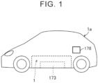
- FIG. 1 shows an electrified vehicle equipped with a thermal management system according to the present disclosure.
- an electrified vehicle 1a is a battery electric vehicle (BEV), and includes a battery 173 and an inlet 178.
- the battery 173 stores traction power for the electrified vehicle 1a.
- the battery 173 is configured to be charged externally with charging power supplied through the inlet 178 from charging equipment (not shown) external to the electrified vehicle 1a.
- the electrified vehicle 1a is an example of the "electrical apparatus" of the present disclosure.
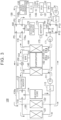
- FIG. 2 shows an example of the overall configuration of a thermal management system 1 according to the first embodiment of the present disclosure.
- the thermal management system 1 includes a thermal management circuit 100, an electronic control unit (ECU) 500, a human machine interface (HMI) 600, a start switch (ST-SW) 650, and a system main relay (SMR) 700.
- ECU electronice control unit
- HMI human machine interface
- ST-SW start switch
- SMR system main relay
- the thermal management circuit 100 is configured so that a heat medium flows therethrough.
- the thermal management circuit 100 includes a high temperature circuit 110, a radiator 120, a grille shutter 124, a low temperature circuit 130, a condenser 140, a refrigeration cycle 150, a chiller 160, a battery circuit 170, a five-way valve 180, and a five-way valve 190.
- the five-way valves 180, 190 are an example of the "switching device" of the present disclosure.
- the chiller 160 is an example of the "chiller device" of the present disclosure.
- the high temperature circuit 110 is an example of the "heater circuit" of the present disclosure, and includes a water pump (W/P) 111, an electric heater 112, a three-way valve 113, a heater core 114, and a reservoir tank (R/T) 115.
- W/P water pump
- R/T reservoir tank
- the radiator 120 is connected to (i.e., shared by) both the high temperature circuit 110 and the low temperature circuit 130.
- the radiator 120 includes a high temperature (HT) radiator 121 and a low temperature (LT) radiator 122 (see FIG. 3 ).
- the low temperature radiator 122 exchanges heat between the heat medium flowing in the low temperature circuit 130 and outside air.
- the low temperature radiator 122 is an example of the "radiator" of the present disclosure.
- the grille shutter 124 is mounted for the radiator 120.
- the grille shutter 124 is configured to open and close according to a command from the ECU 500, and is configured to adjust the amount of heat that is dissipated from the radiator 120 to the outside of the electrified vehicle 1a.
- the low temperature circuit 130 includes a water pump 131, a smart power unit (SPU) 132, a motor 133-1, a power control unit (PCU) 133-2, an oil cooler (O/C) 134, a buck-boost converter 135, a reservoir tank 136, and temperature sensors 137, 138.
- the PCU 133-2 includes a converter and an inverter.
- the motor 133-1 and the PCU 133-2 are also referred to as "transaxle 133.”
- the transaxle 133 is configured to be connected to the battery 173, and is configured to generate a driving force for the electrified vehicle 1a.
- the transaxle 133 is an example of the "drive device" of the present disclosure.
- the temperature sensor 137 may be an example of the "temperature sensor.”
- the temperature sensor 138 may be an example of the "temperature sensor,” and is also an example of the "second temperature sensor.”
- the condenser 140 is connected to both the high temperature circuit 110 and the refrigeration cycle 150.
- the refrigeration cycle 150 includes a compressor 151, an expansion valve 152, an evaporator 153, an evaporative pressure regulator (EPR) 154, and an expansion valve 155.
- EPR evaporative pressure regulator
- the chiller 160 is connected to both the refrigeration cycle 150 and the battery circuit 170.
- the chiller 160 exchanges heat between the heat medium flowing in the battery circuit 170 and the heat medium circulating in the refrigeration cycle 150.
- the battery circuit 170 includes a water pump 171, an electric heater 172, a battery 173, a bypass path 174, and a temperature sensor 175.
- the battery 173 is an example of the "energy storage device” of the present disclosure.
- the temperature sensor 175 is an example of the "first temperature sensor” of the present disclosure.
- Each of the five-way valves 180, 190 is connected to the low temperature circuit 130 and the battery circuit 170.
- the configuration of the thermal management circuit 100 will be described in detail later with reference to FIG. 3 .
- the ECU 500 controls the thermal management circuit 100.
- the ECU 500 includes a processor 501, a memory 502, a storage 503, and an interface 504.
- the processor 501 is, for example, a central processing unit (CPU).
- the memory 502 is, for example, a random access memory (RAM).
- the storage 503 is a rewritable nonvolatile memory such as a hard disk drive (HDD) or a solid state drive (SSD).
- the storage 503 stores system programs including an operating system (OS), and control programs including computer-readable codes that are necessary for control calculations.
- the processor 501 implements various processes by reading the system programs and the control programs, loading them into the memory 502, and executing them.
- the interface 504 allows communication between the ECU 500 and components of the thermal management circuit 100.
- the ECU 500 generates control commands based on sensor values acquired from various sensors (e.g., battery temperature sensor 175) included in the thermal management circuit 100, user operations received by the HMI 600 or the start switch 650, etc.
- the ECU 500 outputs the generated control commands to various circuits (various devices) of the electrified vehicle 1a such as the thermal management circuit 100.
- the ECU 500 is configured to control the current of the battery 173 (perform charge control or discharge control) by controlling switching of the inverter of the PCU 133-2.
- the ECU 500 thus controls heat that is generated due to power loss in the internal resistance of the battery 173.
- the ECU 500 can perform a heating control for increasing the temperature of the battery 173 (perform heating of the battery 173) by causing a current to flow through the battery 173 (by charging or discharging) (self-heating of the battery 173).
- the ECU 500 performs the heating control after a traction system (described later) of the electrified vehicle 1a is activated.
- the ECU 500 is also configured to control the five-way valves 180, 190, control on and off of the SMR 700, and perform an external charging control for controlling external charging.
- the HMI 600 receives user operations for controlling the thermal management system 1.
- the user operations include a heating request operation for heating the vehicle cabin of the electrified vehicle 1a. Heating the vehicle cabin also includes pre-heating that starts at the time scheduled by a user.
- the HMI 600 outputs signals indicating user operations to the ECU 500.
- the SMR 700 is located between the transaxle 133 (specifically, the PCU 133-2) and the battery 173.
- the start switch 650 is operated by the user to activate the traction system of the electrified vehicle 1a.
- the traction system is composed of the transaxle 133, the battery 173, and the SMR 700.
- the ECU 500 turns on the SMR 700 (switches the SMR 700 from the open state to the closed state).
- the transaxle 133 is thus connected to the battery 173 via the SMR 700.
- the traction system is activated.
- activating the traction system is equivalent to turning on the SMR 700.
- FIG. 3 shows an example of the configuration of the thermal management circuit 100 according to the first embodiment.
- the high temperature circuit 110 is formed so that it can exchange heat with the heat medium in a flow path 130b via the condenser 140, the refrigeration cycle 150, the chiller 160, and the five-way valves 180, 190, and is configured to heat the vehicle cabin of the electrified vehicle 1a.
- the heat medium usually hot water
- the heat medium circulating in the high temperature circuit 110 flows through either or both of a first path and a second path.
- the first path is a path of "water pump 111 - condenser 140 - electric heater 112 - three-way valve 113 - heater core 114 - reservoir tank 115 - water pump 111.”
- the second path is a path of "water pump 111 - condenser 140 - electric heater 112 - three-way valve 113 - high temperature radiator 121 - reservoir tank 115 - water pump 111.”
- the heat medium (coolant) circulating in the low temperature circuit 130 flows through the following path: "water pump 131 - SPU 132 - PCU 133-2 (transaxle 133) - oil cooler 134 - buck-boost converter 135 - five-way valve 180 - low temperature radiator 122 - five-way valve 190 - reservoir tank 136 - water pump 131.”
- the water pump 131 circulates the heat medium in the low temperature circuit 130 according to a control command from the ECU 500.
- the SPU 132 controls charge and discharge of the battery 173 according to a control command from the ECU 500.
- the PCU 133-2 converts direct current (DC) power supplied from the battery 173 to alternating current (AC) power to supply the AC power to the motor 133-1 according to a control command from the ECU 500.
- the oil cooler 134 circulates lubricating oil for the motor 133-1 by using an electrical oil pump (EOP) (not shown). The oil cooler 134 cools the motor 133-1 (transaxle 133) through heat exchange between the heat medium circulating in the low temperature circuit 130 and the lubricating oil for the motor 133-1.
- EOP electrical oil pump
- the temperature sensor 137 detects the temperature of the transaxle 133 (specifically, the PCU 133-2).
- the temperature sensor 138 is located downstream of the transaxle 133 in the flow path 130b (described later), and detects the temperature of the heat medium in the flow path 130b.
- the SPU 132, the PCU 133-2, the oil cooler 134, and the buck-boost converter 135 are cooled by the heat medium circulating in the low temperature circuit 130.
- the reservoir tank 136 stores part of the heat medium flowing in the low temperature circuit 130 to maintain the pressure and amount of heat medium in the low temperature circuit 130.
- Each of the five-way valves 180, 190 switches the path of the heat medium in the low temperature circuit 130 and the battery circuit 170 according to a control command from the ECU 500.
- the low temperature radiator 122 is disposed near the high temperature radiator 121, and exchanges heat with the high temperature radiator 121.
- the first path is a path of "compressor 151 - condenser 140 - expansion valve 152 - evaporator 153 - EPR 154 - compressor 151.”
- the second path is a path of "compressor 151 - condenser 140 - expansion valve 155 - chiller 160 - compressor 151.”
- the heat medium (coolant) circulating in the battery circuit 170 flows through either or both of a first path and a second path.
- the first path is a path of "water pump 171 - chiller 160 - five-way valve 180 - electric heater 172 - battery 173 - five-way valve 190 - water pump 171.”
- the second path is a path of "water pump 171 - chiller 160 - five-way valve 180 - bypass path 174 - five-way valve 190 - water pump 171.”
- the water pump 171 circulates the heat medium in the battery circuit 170 according to a control command from the ECU 500.
- the chiller 160 cools the heat medium circulating in the battery circuit 170 through heat exchange between the heat medium circulating in the refrigeration cycle 150 and the heat medium circulating in the battery circuit 170.
- the electric heater 172 heats the heat medium according to a control command from the ECU 500.
- the battery 173 may be heated with the electric heater 172 or may be cooled with the chiller 160.
- the bypass path 174 is provided to allow the heat medium to bypass the electric heater 172 and the battery 173. When the heat medium flows through the bypass path 174, a change in temperature of the heat medium associated with heat absorption and heat dissipation between the heat medium and the battery 173 can be reduced.
- the temperature sensor 175 detects the temperature of the battery 173.
- the five-way valve 180 includes ports P1 to P5.
- the port P1 is an inlet port into which the heat medium flows from the chiller 160.
- the port P2 is an outlet port from which the heat medium flows toward the electric heater 172 and the battery 173 of the battery circuit 170.
- the port P3 is an inlet port into which the heat medium flows from the SPU 132, the PCU 133-2, the oil cooler 134, and the buck-boost converter 135 of the low temperature circuit 130.
- the port P4 is an outlet port from which the heat medium flows toward the bypass path 174 of the battery circuit 170.
- the port P5 is an outlet port from which the heat medium flows toward the low temperature radiator 122.
- the five-way valve 190 includes ports P11 to P15.
- the port P11 is an outlet port from which the heat medium flows toward the chiller 160.
- the port P12 is an inlet port into which the heat medium flows from the electric heater 172 and the battery 173 of the battery circuit 170.
- the port P13 is an outlet port from which the heat medium flows toward the SPU 132, the PCU 133-2, the oil cooler 134, and the buck-boost converter 135 of the low temperature circuit 130.
- the port P14 is an inlet port into which the heat medium flows from the bypass path 174 of the battery circuit 170.
- the port P15 is an inlet port into which the heat medium flows from the low temperature radiator 122.
- the five-way valves 180, 190 are configured to switch the connection state between a flow path 130a, the flow path 130b, a flow path 170a, and a flow path 170b (all of which will be described below) according to a command from the ECU 500.
- the battery 173 is provided in the flow path 170b of the battery circuit 170.
- the battery 173 exchanges heat with the heat medium in the flow path 170b.
- the flow path 170b is in thermal contact with the battery 173.
- the flow path 170b is a flow path connecting the port P2 of the five-way valve 180 and the port P12 of the five-way valve 190.
- the heat medium can flow through the flow path 170b.
- the flow path 170b is an example of the "first flow path" of the present disclosure.
- the low temperature radiator 122 is provided in the flow path 130a of the low temperature circuit 130.
- the flow path 130a is a flow path connecting the port P5 of the five-way valve 180 and the port P15 of the five-way valve 190.
- the heat medium can flow through the flow path 130a.
- the flow path 130a is an example of the "third flow path" of the present disclosure.
- the water pump 131, the SPU 132, the PCU 133-2 (transaxle 133), the oil cooler 134, the buck-boost converter 135, and the reservoir tank 136 are provided in the flow path 130b of the low temperature circuit 130.
- the PCU 133-2 (transaxle 133) etc. exchange heat with the heat medium in the flow path 130b.
- the flow path 130b is in thermal contact with the SPU 132, the PCU 133-2 (transaxle 133), the oil cooler 134, and the buck-boost converter 135.
- the flow path 130b is a flow path connecting the port P3 of the five-way valve 180 and the port P13 of the five-way valve 190.
- the heat medium can flow through the flow path 130b.
- the flow path 130b is an example of the "second flow path" of the present disclosure.
- the chiller 160 is provided in the flow path 170a of the battery circuit 170.
- the flow path 170a is a flow path connecting the port P1 of the five-way valve 180 and the port P11 of the five-way valve 190.
- the heat medium can flow through the flow path 170a.
- the flow path 170a is an example of the "fourth flow path" of the present disclosure.
- FIG. 4 is a conceptual diagram showing an overview of a predetermined communication pattern (hereinafter sometimes referred to as "reference communication pattern") of the thermal management circuit 100 that is formed by controlling the five-way valves 180, 190.
- the reference communication pattern is an example of the "switching circuit" of the present disclosure.
- the electrified vehicle 1a Since the electrified vehicle 1a is not equipped with an engine, it is not possible to use engine waste heat to heat components of the electrified vehicle 1a that are to be heated. Therefore, it is sometimes important to effectively use the heat generated by the transaxle 133. Moreover, when the heat generated by the battery 173 is transferred to components such as the radiator 120 via the heat medium during the heating control of the battery 173 performed by the ECU 500, the heat may be taken from the battery 173 and the heating control may not be effectively performed. It is therefore desired to efficiently perform the heating control of the battery 173.
- the ECU 500 controls the five-way valves 180, 190 to cause the reference communication pattern formed ( FIG. 4 ).
- the five-way valve 180 forms a path connecting the ports P1, P5 and a path connecting the ports P3, P4.
- the five-way valve 190 forms a path connecting the ports P11, P14 and a path connecting the ports P13, P15.
- the flow path 170b is disconnected from and independent of the bypass path 174 and the flow paths 130a, 130b, and 170a.
- the flow path 130b is connected to the bypass path 174, the flow path 130a, and the flow path 170a.
- the flow path 130a is connected to the flow path 170a.
- the ECU 500 preferably controls the grille shutter 124 to the closed state when the reference communication pattern is formed.
- the amount of heat that is dissipated from the low temperature radiator 122 to the outside of the electrified vehicle 1a is smaller than when the grille shutter 124 is in the open state.
- the amount of heat that is dissipated from the low temperature radiator 122 to the outside of the electrified vehicle 1a can be reduced.
- the heat generated by the transaxle 133 (PCU 133-2) can thus be effectively stored in the heat medium in the flow path 130a, the flow path 130b, and the flow path 170a.
- the ECU 500 may switch the grille shutter 124 from the closed state to the open state when the value of the temperature related to the temperature of the transaxle 133 (e.g., the detected value from the temperature sensor 137 or the detected value from the temperature sensor 138) becomes higher than a predetermined threshold.
- the threshold is experimentally determined in advance as a value that is higher than a reference value that will be described later and as such a value that the transaxle 133 is protected from overheating when the above value of the temperature is less than the threshold.
- FIG. 5 is a flowchart illustrating a process that is performed by the ECU 500 according to the first embodiment.
- step is abbreviated as "S.”
- the ECU 500 starts driving the electrified vehicle 1a (activates the traction system) (S10). Specifically, the ECU 500 turns on the SMR 700 in response to an operation (pressing) of the start switch 650.
- the ECU 500 determines whether the temperature of the battery 173 detected by the temperature sensor 175 is lower than a predetermined reference temperature (e.g., 10°C) (S15). When the temperature of the battery 173 is equal to or higher than the reference temperature (No in S15), the process ends. When the temperature of the battery 173 is lower than the reference temperature (Yes in S15), the process proceeds to step S20.
- a predetermined reference temperature e.g. 10°C
- the ECU 500 starts the heating control by performing charge control or discharge control of the battery 173 (S20).
- the ECU 500 controls the five-way valves 180, 190 so that the thermal management circuit 100 has the reference communication pattern ( FIG. 4 ) (S25), and controls the grille shutter 124 to the closed state (S30).
- the ECU 500 may perform S20, S25, and S30 simultaneously.
- the ECU 500 determines whether the value TV of the temperature related to the temperature of the transaxle 133 is higher than a threshold TH (S35). When the value TV is equal to or less than the threshold TH (No in S35), the ECU 500 controls the grille shutter 124 to the closed state (S40). When the grille shutter 124 is in the closed state immediately before S40, the grille shutter 124 is kept in the closed state. When the value TV is higher than the threshold TH (Yes in S35), the ECU 500 controls the grille shutter 124 to the open state (S45). When the grille shutter 124 is in the closed state immediately before S45, the grille shutter 124 is switched from the closed state to the open state.
- a threshold TH S35
- the ECU 500 determines whether the temperature of the battery 173 detected by the temperature sensor 175 exceeds the reference temperature (S50). When the temperature of the battery 173 is equal to or lower than the reference temperature (No in S50), the process returns to S35. When the temperature of the battery 173 exceeds the reference temperature (Yes in S50), the heating control of the battery 173 by the ECU 500 ends, and the process proceeds to S60.
- the ECU 500 controls the five-way valves 180, 190 to change the communication pattern of the thermal management circuit 100 from the reference communication pattern ( FIG. 4 ) to a different communication pattern (e.g., a communication pattern suitable for traveling of the electrified vehicle 1a) (S60). The process then ends.
- the first embodiment it is possible to allow effective use of heat generated by the transaxle 133 while reducing or eliminating the possibility of heat being taken from the battery 173 during the heating control.
- the ECU 500 supplies heat from the transaxle 133 to the high temperature circuit 110 via the chiller 160 by driving the high temperature circuit 110 (specifically, the water pump 111 and optionally the electric heater 112) with the reference communication pattern formed.
- the heat from the transaxle 133 (heat stored in the heat medium in the flow path 130b) is supplied to the heater core 114 via the chiller 160, the refrigeration cycle 150, and the condenser 140 in response to a heating request.
- the heat from the electric heater 112 but also the heat from the transaxle 133 can thus be used to heat the vehicle cabin.
- the amount of heat that needs to be generated by the electric heater 112 to heat the vehicle cabin can be reduced (burden on the electric heater 112 can be reduced).
- FIG. 6 is a flowchart illustrating a process that is performed by the ECU 500 according a first modification of the first embodiment. This flowchart is different from the flowchart of the first embodiment ( FIG. 5 ) in that S37, S42, and S47 are performed instead of S35, S40, and S45, respectively.
- the ECU 500 determines whether a heating request operation has been performed (whether there is a heating request). When there is a heating request (Yes in S37), the ECU 500 drives a heating circuit (S42). When there is no heating request (No in S37), the ECU 500 does not drive the heating circuit (S47). For example, S47 is a step of stopping the heating circuit when a request is made to stop the heating while the heating circuit is being driven. After S42 or S47, the process proceeds to S50.
- the heat from the transaxle 133 can be stored in the heat medium in the flow path 130b, and the stored heat can be used to heat the vehicle cabin.
- the ECU 500 may control (switch) the five-way valves 180, 190 so that the flow path 170b is connected to the flow path 130b.
- the temperature of the heat medium in the flow path 130b is higher than the temperature of the battery 173.
- the five-way valves 180, 190 are controlled as described above, the heat stored in the heat medium in the flow path 130b is transferred to the battery 173.
- the battery 173 is thus heated by the heat stored in the heat medium in the flow path 170b (heat derived from the transaxle 133) in addition to the heat generated due to the internal resistance of the battery 173 during the heating control of the battery 173. As a result, heating of the battery 173 can further be facilitated.
- FIG. 7 is a flowchart illustrating a process that is performed by the ECU 500 according a second modification of the first embodiment. This flowchart is different from the flowchart of the first embodiment ( FIG. 5 ) in that S39, S44, and S49 are performed instead of S35, S40, and S45, respectively.
- the ECU 500 determines whether the detected value TV1 from the temperature sensor 138 is higher than the detected value TV2 from the temperature sensor 175 (S39).
- the ECU 500 controls the five-way valves 180, 190 so that the thermal management circuit 100 has the reference communication pattern (S44).
- the ECU 500 controls the five-way valves 180, 190 so that the flow path 170b is connected to the flow path 130b (S49).
- the ECU 500 switches the five-way valves 180, 190 so that the communication pattern of the thermal management circuit 100 changes from the reference communication pattern to a communication pattern (not shown) in which the flow path 170b and the flow path 130b are connected. After S44 or S49, the process proceeds to S50.
- heating of the battery 173 can be facilitated during the heating control of the battery 173.
- FIG. 8 illustrates another example of the reference communication pattern of the thermal management circuit 100.
- the reference communication pattern is not limited to the pattern shown in FIG. 4 and may be a different pattern as shown in FIG. 8 as long as the flow path 170b is disconnected from and independent of the bypass path 174 and the flow paths 130a, 130b, and 170a, the flow path 130b is connected to the flow paths 130a, 170a, and the flow path 130a is connected to the flow path 170a.
- the configuration using the five-way valves 180, 190 is described in the first embodiment.
- the configuration of the switching device according to the present disclosure is not limited to this.
- the configuration in which the switching device according to the present disclosure is a ten-way valve 280 will be described in a second embodiment.
- FIG. 9 shows an example of the overall configuration of a thermal management system 2 according to the second embodiment of the present disclosure.
- the thermal management system 2 is different from the thermal management system 1 according to the first embodiment (see FIG. 1 ) in that the thermal management system 2 includes a thermal management circuit 200 instead of the thermal management circuit 100 and includes an ECU 510 instead of the ECU 500.
- the thermal management circuit 200 includes a chiller circuit 210, a chiller 220, a radiator circuit 230, a refrigeration cycle 240, a condenser 250, a drive unit circuit 260, a battery circuit 270, and a ten-way valve 280.
- the ten-way valve 280 is an example of the "switching device" of the present disclosure.
- the chiller circuit 210 includes a water pump (W/P) 211.
- the chiller 220 is connected to (shared by) both the chiller circuit 210 and the refrigeration cycle 240.
- the chiller 220 is an example of the "chiller device" of the present disclosure.
- the radiator circuit 230 includes a radiator 231 and a grille shutter 234.
- the refrigeration cycle 240 includes a compressor 241, an electromagnetic valve 242 (see FIG. 10 ), electromagnetic valves 244A, 244B, 245, and 246 (see FIG. 10 ), an evaporator 247, a check valve 248, and an accumulator 249.
- the condenser 250 includes a water-cooled condenser 251 and an air-cooled condenser 252 (see FIG. 10 ), and the water-cooled condenser 251 is connected to both the refrigeration cycle 240 and the radiator circuit 230.
- the chiller 220, the compressor 241, the accumulator 249, and the condenser 250 form an example of the "heating circuit" of the present disclosure.
- the drive unit circuit 260 includes a water pump 261, an SPU 262, a transaxle 263 (motor 263-1 and PCU 263-2), an oil cooler 264, a reservoir tank 265, and temperature sensors 266, 267.
- the transaxle 263 is an example of the "drive device” of the present disclosure.
- the transaxle 263, a battery 272, and the SMR 700 form an example of the "traction system" of the present disclosure.
- the battery circuit 270 includes advanced driver-assistance systems (ADAS) 271, the battery 272, and a temperature sensor 273.
- ADAS advanced driver-assistance systems
- the battery 272 is an example of the "energy storage device” of the present disclosure.
- the temperature sensor 273 is an example of the "first temperature sensor” of the present disclosure.
- the ten-way valve 280 includes ports P20 to P29 (see FIGS. 10 to 11B ), and is connected to the chiller circuit 210, the radiator circuit 230, the drive unit circuit 260, and the battery circuit 270.
- the ECU 510 controls the thermal management circuit 200.
- the ECU 510 includes a processor 511, a memory 512, a storage 513, and an interface 514.
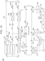
- FIG. 10 shows an example of the configuration of the thermal management circuit 200 according to the second embodiment.
- a heat medium circulating in the chiller circuit 210 flows through the following path: "ten-way valve 280 (port P23) - water pump 211 - chiller 220 - ten-way valve 280 (port P25)."
- the water pump 211 circulates the heat medium in the chiller circuit 210 according to a control command from the ECU 510.
- the chiller 220 exchanges heat between the heat medium circulating in the chiller circuit 210 and the heat medium circulating in the refrigeration cycle 240.
- the ten-way valve 280 switches the path to which the chiller circuit 210 is connected according to a control command from the ECU 510. The switching of the path by the ten-way valve 280 will be discussed in detail later.
- the heat medium that can flow through the radiator circuit 230 can flow through the following path: ten-way valve 280 (port P29) - ten-way valve 280 (port P27).
- the heat medium can also flow through the following path: ten-way valve 280 (port P26) - water-cooled condenser 251 - radiator 231 - ten-way valve 280 (port P27).
- the radiator 231 exchanges heat between the heat medium and the air outside the electrified vehicle 1a.
- the grille shutter 234 is mounted for the radiator 231.
- the first path is a path of "compressor 241 - electromagnetic valve 244A - air-cooled condenser 252 - check valve 248 - electromagnetic valve (expansion valve) 245 - evaporator 247 - accumulator 249 - compressor 241.”
- the second path is a path of "compressor 241 - electromagnetic valve 244A - air-cooled condenser 252 - check valve 248 - electromagnetic valve (expansion valve) 246 - chiller 220 - accumulator 249 - compressor 241.”
- the third path is a path of "compressor 241 - electromagnetic valve 244B - water-cooled condenser 251 - electromagnetic valve (expansion valve) 245 - evaporator 247 - accumulator 249 - compressor 241.”
- the fourth path is
- the compressor 241 compresses the gas-phase refrigerant circulating in the refrigeration cycle 240 according to a control command from the ECU 510.
- the electromagnetic valve 242 is connected in parallel with the compressor 241, and adjusts the amount of gas-phase refrigerant flowing into the compressor 241 according to a control command from the ECU 510.
- the electromagnetic valves 244 (244A, 244B) selectively allow the gas-phase refrigerant discharged from the compressor 241 to flow into either the water-cooled condenser 251 or the air-cooled condenser 252 according to a control command from the ECU 510.
- the electromagnetic valve 245 restricts the flow of the liquid-phase refrigerant into the evaporator 247 according to a control command from the ECU 510.
- the electromagnetic valve 246 restricts the flow of the liquid-phase refrigerant into the chiller 220 according to a control command from the ECU 510.
- the electromagnetic valves 245, 246 also have a function to expand the liquid-phase refrigerant.
- the accumulator 249 removes the liquid-phase refrigerant from the refrigerant in a gas-liquid mixed state. The accumulator 249 thus reduces or eliminates the possibility that the liquid-phase refrigerant may be sucked into the compressor 241 when the refrigerant is not completely evaporated by the evaporator 247.
- the heat medium (coolant) circulating in the drive unit circuit 260 flows through the following path: "ten-way valve 280 (port P28) - reservoir tank 265 - water pump 261 - SPU 262 - PCU 263-2 (transaxle 263) - oil cooler 264 - ten-way valve 280 (port P22)."
- the water pump 261 circulates the heat medium in the drive unit circuit 260 according to a control command from the ECU 510.
- the SPU 262 controls charge and discharge of the battery 272 according to a control command from the ECU 510.
- the PCU 263-2 converts DC power supplied from the battery 272 to AC power to supply the AC power to the motor 263-1 of the transaxle 263 according to a control command from the ECU 510.
- the oil cooler 264 cools the transaxle 263 through heat exchange between the heat medium circulating in the drive unit circuit 260 and lubricating oil for the motor 263-1.
- Heat exchange may be performed between heat generated by supplying power to a stator without rotating a rotor of the motor 263-1 and the heat medium circulating in the drive unit circuit 260.
- the SPU 262, the PCU 263-2, and the oil cooler 264 are cooled by the heat medium circulating in the drive unit circuit 260.
- the reservoir tank 265 stores part of the heat medium circulating in the drive unit circuit 260 (heat medium that has overflowed due to a pressure increase) to maintain the pressure and amount of heat medium in the drive unit circuit 260.
- the temperature sensor 266 may be an example of the "temperature sensor” of the present disclosure, and detects the temperature of the transaxle 263.
- the temperature sensor 267 is an example of the “temperature sensor” or “second temperature sensor” of the present disclosure, and detects the temperature of the heat medium in a flow path 260a (described later).
- the temperature detected by the temperature sensor 266 or the temperature detected by the temperature sensor 267 is the temperature related to the temperature of the transaxle 263.
- the heat medium (coolant) circulating in the battery circuit 270 flows through the following path: "ten-way valve 280 (port P21) - ADAS 271 - battery 272 - ten-way valve 280 (port P24)."
- the heat medium can also flow through the following path: ten-way valve 280 (port P21) - ADAS 271 - ten-way valve 280 (port P20).
- the ADAS 271 includes auto speed limiter (ASL) and lane keeping assist (LKA).
- ASL auto speed limiter
- LKA lane keeping assist
- the battery 272 supplies traction power to the motor 263-1.
- the temperature sensor 273 detects the temperature of the battery 272.
- the chiller 220 is provided in a flow path 210a (see FIGS. 11A and 11B ) of the chiller circuit 210.
- the flow path 210a is a flow path connecting the ports P23, P25 of the ten-way valve 280.
- the flow path 210a is an example of the "fourth flow path" of the present disclosure.
- the radiator 231 is provided in a flow path 230a (see FIGS. 11A and 11B ) of the radiator circuit 230.
- the flow path 230a connects the radiator 231 and the ten-way valve 280.
- the flow path 230a is in parallel with a bypass flow path 282a.
- the heat medium flows through the bypass flow path 282a, the heat medium does not flow through the radiator 231 (flow path 230a).
- the heat medium flows through the radiator 231 (flow path 230a)
- the heat medium does not flow through the bypass flow path 282a.
- the flow path 230a is an example of the "third flow path" of the present disclosure.
- the water pump 261, the SPU 262, the PCU 263-2, the oil cooler 264, and the reservoir tank 265 are provided in a flow path 260a (see FIGS. 11A and 11B ) of the drive unit circuit 260.
- the PCU 263-2 (transaxle 263) etc. exchange heat with the heat medium in the flow path 260a.
- the flow path 260a is in thermal contact with the PCU 263-2 etc.
- the flow path 260a is a flow path connecting the ports P22, P28 of the ten-way valve 280.
- the flow path 260a is an example of the "second flow path" of the present disclosure.
- the battery 272 is provided in a flow path 270a (see FIGS. 11A and 11B ) of the battery circuit 270.
- the flow path 270a is a flow path connecting the ports P24, P21 of the ten-way valve 280, and is in parallel with a bypass flow path 282b.
- the battery 272 exchanges heat with the heat medium in the flow path 270a.
- the flow path 270a is in thermal contact with the battery 272.
- the flow path 270a is an example of the "first flow path" of the present disclosure.
- the bypass flow path 282b is a flow path connecting the ports P21, P20 of the ten-way valve 280.
- FIGS. 11A, 11B and FIGS. 12A, 12B are conceptual diagrams showing an overview of an initial communication pattern and a reference communication pattern that are formed by the ten-way valve 280, respectively.
- the ECU 510 starts the heating control and controls the ten-way valve 280 to cause the initial communication pattern formed ( FIGS. 11A and 11B ).
- the following paths are formed in the initial communication pattern: a path connecting the ports P21, P20, a path connecting the ports P23, P25, a path connecting the ports P27, P29, and a path connecting the ports P22, P28.
- the flow path 210a is a flow path connecting the port P23 to the port P25.
- the flow path 230a is a flow path connecting the port P26 to the port P27.
- the flow path 260a is a flow path connecting the port P22 to the port P28.
- the flow path 270a is a flow path connecting the port P21 to the port P24.
- the heat medium can flow through each of the flow paths 210a, 230a, 260a, and 270a.
- the flow paths 230a, 270a are independent, and the flow paths 210a, 260a are connected.
- the battery 272 is disconnected from and independent of the radiator 231, the chiller 220, and the PCU 263-2 (transaxle 263), the radiator 231 is disconnected from and independent of the chiller 220 and the PCU 263-2, and the chiller 220 is connected to the PCU 263-2.
- This configuration can reduce or eliminate the possibility that heat from the battery 272 may be transferred to the radiator 231 via the heat medium and dissipated from the radiator 231 to the outside of the electrified vehicle 1a during the heating control.
- This configuration can also reduce or eliminate the possibility that heat from the transaxle 263 may be transferred to the radiator 231 via the heat medium and dissipated from the radiator 231. As a result, the heat from the transaxle 263 can be effectively stored in the heat medium in the flow path 260a.
- the ECU 510 controls the ten-way valve 280 to cause the reference communication pattern formed ( FIGS. 12A and 12B ). That is, the ECU 510 switches the communication pattern of the thermal management circuit 200 from the initial communication pattern to the reference communication pattern.
- the reference value is experimentally determined in advance as appropriate in order to protect the transaxle 263 from overheating. The reference value is lower than the threshold described above.
- the heat from the transaxle 263 is transferred to the radiator 231 via the heat medium and is dissipated to the outside of the electrified vehicle 1a. Overheating of the transaxle 263 can thus be avoided.
- FIG. 13 is a flowchart illustrating a control method of the thermal management system 2. Referring to FIG. 13 , this flowchart is different from the flowchart of the first embodiment ( FIG. 6 ) in that S22A and S23 are added and S25A is performed instead of S25. This flowchart is otherwise basically the same as the flowchart of the first embodiment.
- the ECU 510 controls the ten-way valve 280 so that the thermal management circuit 200 has the initial communication pattern ( FIGS. 11A and 11B ) (S22A).
- the ECU 510 determines whether the value MV of the temperature related to the temperature of the transaxle 263 is higher than a reference value RV (S23). When the value MV is equal to or lower than the reference value RV (No in S23), the process returns to S22A. When the value MV is higher than the reference value RV (Yes in S23), the ECU 510 controls the ten-way valve 280 so that the thermal management circuit 200 has the reference communication pattern ( FIGS. 12A and 12B ) (S25A). The process then proceeds to S30.
- the ECU 510 may control the ten-way valve 280 so that the flow path 270a is connected to the flow path 260a.
- a third embodiment uses two six-way valves.
- the same components as those of the second embodiment are denoted by the same signs as those of the second embodiment, and description thereof will not be repeated.
- the thermal management circuit 300 includes the chiller circuit 210, the chiller 220, the radiator circuit 230, the refrigeration cycle 240, the condenser 250, the drive unit circuit 260, the battery circuit 270, a six-way valve 380, and a six-way valve 390.
- the six-way valves 380, 390 are an example of the "switching device" of the present disclosure.
- the chiller 220 is provided in a flow path 210b of the chiller circuit 210.
- the flow path 210b connects the chiller circuit 210 and each of the six-way valves 380, 390.
- the flow path 210b is an example of the "fourth flow path" of the present disclosure.
- the radiator 231 is provided in a flow path 230b.
- the flow path 230b connects the radiator 231 and the six-way valve 390.
- the flow path 230b is an example of the "third flow path" of the present disclosure.
- the water pump 261, the SPU 262, the transaxle 263, the oil cooler 264, and the reservoir tank 265 are provided in a flow path 260b of the drive unit circuit 260.
- the flow path 260b connects the drive unit circuit 260 and each of the six-way valves 380, 390.
- the flow path 260b is in thermal contact with the SPU 262, the transaxle 263, the oil cooler 264, etc.
- the transaxle 263 etc. thus exchange heat with the heat medium in the flow path 260b.
- the flow path 260b is an example of the "second flow path" of the present disclosure.
- the battery 272 is provided in a flow path 270b of the battery circuit 270.
- the flow path 270b connects the battery circuit 270 and the six-way valve 380.
- the flow path 270b is in thermal contact with the battery 272.
- the battery 272 thus exchanges heat with the heat medium in the flow path 270b.
- the flow path 270b is an example of the "first flow path" of the present disclosure.
- the ECU 520 controls the thermal management circuit 300.
- the ECU 520 includes a processor 521, a memory 522, a storage 523, and an interface 524.
- FIG. 15 shows an example of the configuration of the thermal management circuit 300 according to the third embodiment.
- the six-way valve 380 includes ports P31 to P36.
- the six-way valve 390 includes ports P41 to P46.
- the six-way valve 380 is connected to the six-way valve 390. Specifically, the port P35 of the six-way valve 380 and the port P45 of the six-way valve 390 are connected by a flow path 5. The port P36 of the six-way valve 380 and the port P46 of the six-way valve 390 are connected by a flow path 6.
- a heat medium circulating in the chiller circuit 210 flows through the following path: "six-way valve 380 (port P33) - water pump 211 - chiller 220 - six-way valve 390 (port P43)."
- the heat medium circulating in the radiator circuit 230 flows through the following path: "six-way valve 390 (port P41) - radiator 231 - six-way valve 390 (port P44)."
- the heat medium (coolant) circulating in the drive unit circuit 260 flows through the following path: "six-way valve 390 (port P42) - reservoir tank 265 - water pump 261 - SPU 262 - PCU 263-2 - oil cooler 264 - water-cooled condenser 251 - six-way valve 380 (port P32)."
- the heat medium (coolant) circulating in the battery circuit 270 flows through the following path: "six-way valve 380 (port P31) - ADAS 271 - battery 272 - six-way valve 380 (port P34)."
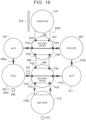
- FIG. 16 is a conceptual diagram showing an overview of an initial communication pattern of the thermal management circuit 300 that is formed by controlling the six-way valves 380, 390.
- the six-way valve 380 forms a path connecting the ports P32, P33, a path connecting the ports P35, P36 (flow path 290), and a path connecting the ports P31, P34 (flow path 270b).
- the six-way valve 390 forms a path connecting the ports P42, P43, a path connecting the ports P45, P46 (flow path 290), and a path connecting the ports P41, P44 (flow path 230b).
- heat from the transaxle 263 can be effectively stored in the heat medium in the flow paths 210b, 260b, as in the second embodiment.
- FIG. 17 is a conceptual diagram showing an overview of a reference communication pattern of the thermal management circuit 300 that is formed by controlling the six-way valves 380, 390.
- the ECU 520 controls the six-way valves 380, 390 to cause the reference communication pattern formed (switch the communication pattern from the initial communication pattern to the reference communication pattern).
- the flow path 270b is disconnected from and independent of the flow paths 210b, 230b, and 260b
- the flow path 260b is connected to the flow paths 210b, 230b
- the flow path 230b is connected to the flow path 210b. Overheating of the transaxle 263 can thus be avoided as in the second embodiment.
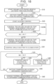
- FIG. 18 is a flowchart illustrating a control method of the thermal management system 3. Referring to FIG. 18 , this flowchart is different from the flowchart of the second embodiment ( FIG. 13 ) in that S22B and S25B are performed instead of S22A and S25A, respectively. This flowchart is otherwise the same as the flowchart of the second embodiment.
- the ECU 520 controls the six-way valves 380, 390 so that the thermal management circuit 300 has the initial communication pattern ( FIG. 16 ) (S22B). Thereafter, when the value MV exceeds the reference value RV (Yes in S23), the ECU 520 controls the six-way valves 380, 390 so that the thermal management circuit 300 has the reference communication pattern ( FIG. 17 ) (S25B).
- the ECU 520 may cause the reference communication pattern formed instead of the initial communication pattern when the traction system is activated (at the start of the heating control).
- the ECU 520 may supply heat from the transaxle 263 to the heating circuit via the chiller 220 by driving the heating circuit with the reference communication pattern formed.
- the ECU 520 may control the six-way valves 380, 390 so that the flow path 270b is connected to the flow path 260b.
- FIGS. 19 , 20 , and 21 illustrates other examples of the reference communication pattern of the thermal management circuit 300.
- the reference communication pattern is not limited to the pattern shown in FIG. 17 and may be the pattern shown in FIGS. 19 , 20 , or 21 as long as the flow path 270b is disconnected from and independent of the flow paths 210b, 230b, and 260b, the flow path 260b is connected to the flow paths 210b, 230b, and the flow path 230b is connected to the flow path 210b.
- the first to third embodiments illustrate an example in which the heating control of the battery is performed at the start of driving of the electrified vehicle 1a (when the traction system is activated).
- the present disclosure is not limited to this.
- FIG. 22 is a flowchart illustrating a process that is performed by the ECU according a modification.
- the ECU may perform the heating control so that the temperature of the battery 173 becomes equal to or higher than a predetermined reference temperature at the start of external charging (see S62 in FIG. 22 ).
- a predetermined reference temperature at the start of external charging.
- step S11 when the ECU detects that a charging plug of charging equipment is plugged in (inserted) into the inlet 178, the process proceeds to step S15.
- the process proceeds to step S62.
- step S62 the ECU starts external charging control
- FIG. 22 illustrates an example in which plugging in triggers the battery heating control.
- the battery heating control may be started before plugging in.
- the battery heating control may be started a predetermined time (e.g., 10 minutes) before the scheduled start time of external charging (scheduled start time of supplying charging power).
- the above control is representatively applied to the first embodiment.
- the above control may be applied to the second or third embodiment.
- the first to third embodiments illustrate an example in which the thermal management system is mounted on an electrified vehicle.
- the thermal management system may be mounted on an electrical apparatus different from an electrified vehicle (e.g., a stationary energy storage device).
- the first embodiment illustrates an example in which the thermal management circuit 100 includes the high temperature circuit 110.
- the thermal management circuit 100 may not include the high temperature circuit 110.
- the second embodiment illustrates an example in which the thermal management circuit 200 includes the ten-way valve 280.
- the thermal management circuit 100 may include the ten-way valve 280 (see FIG. 23 ).
- the third embodiment illustrates an example in which the thermal management circuit 300 includes the six-way valves 380, 390.
- the thermal management circuit 100 may include the six-way valves 380, 390 (see FIG. 24 ).
- the first to third embodiments illustrate an example in which the battery heating control is performed at the start of driving of the electrified vehicle 1a (when the traction system is activated).
- the heating control need not necessarily be performed at the start of driving of the electrified vehicle 1a (when the traction system is activated).
- the heating control may be performed when the battery temperature falls below a reference temperature.
- the ECU may acquire the detected value of the battery temperature at predetermined intervals (e.g., every hour).
- the electrified vehicle 1a may be a hybrid electric vehicle (HEV), a plug-in hybrid electric vehicle (PHEV), or a fuel cell electric vehicle (FCEV).
- HEV hybrid electric vehicle
- PHEV plug-in hybrid electric vehicle
- FCEV fuel cell electric vehicle
- the thermal management system according to the present disclosure is not limited to vehicle applications.
- FIG. 25 illustrates the battery heating control in detail.
- the PCU 133-2 includes a converter 810 and an inverter 820.
- the battery 173 is connected to the converter 810 via a system main relay (SMR) 700.
- the converter 810 is connected to the inverter 820.
- the inverter 820 is connected to the motor 133-1.
- a discharge circuit 840 including a switch and a resistive element is connected to the battery 173.
- a smoothing capacitor 850 is provided between the battery 173 and the converter 810.
- a discharge circuit 860 includes a switch and a resistive element, and is connected in parallel with the smoothing capacitor 850.
- FIG. 25 is representatively illustrated based on the configuration of the first embodiment. However, the same configuration may be applied to any of the second and third embodiments and their modifications.
- the heating control of the battery 173 may include, for example, a control for electrically disconnecting the SMR 700 and turning on the switch of the discharge circuit 840. In this case, a current flows through a closed circuit formed by the battery 173 and the discharge circuit 840.
- the heating control of the battery 173 may include a control for turning off the switch of the discharge circuit 840 and turning on the SMR 700 and the switch of the discharge circuit 860. In this case, a current flows through a closed circuit formed by the battery 173, the SMR 700, and the discharge circuit 860.
- the heating control of the battery 173 may include a control for turning on the SMR 700 and turning off the switches of the discharge circuits 840, 860 to cause a current adjusted so that no torque is generated in the motor 133-1 to flow.
Landscapes
- Engineering & Computer Science (AREA)
- Mechanical Engineering (AREA)
- Chemical & Material Sciences (AREA)
- Combustion & Propulsion (AREA)
- Transportation (AREA)
- Physics & Mathematics (AREA)
- Thermal Sciences (AREA)
- General Chemical & Material Sciences (AREA)
- Manufacturing & Machinery (AREA)
- Chemical Kinetics & Catalysis (AREA)
- Electrochemistry (AREA)
- Sustainable Energy (AREA)
- Sustainable Development (AREA)
- Life Sciences & Earth Sciences (AREA)
- Power Engineering (AREA)
- General Engineering & Computer Science (AREA)
- Automation & Control Theory (AREA)
- Electric Propulsion And Braking For Vehicles (AREA)
- Air-Conditioning For Vehicles (AREA)
- Secondary Cells (AREA)
Abstract
Description
- The present disclosure relates to thermal management systems.
-
Japanese Unexamined Patent Application Publication No. 2010-272395 JP 2010-272395 A - A thermal management system that is mounted on an electrical apparatus such as an electrified vehicle includes a plurality of flow paths through which a heat medium flows, an energy storage device, a drive device (motor and inverter), a radiator, a chiller device, and a switching device (e.g., a switching valve). The energy storage device, the drive device, the radiator, and the chiller device are provided in different flow paths. The switching device switches the connection state between the flow paths.
- If the switching device is not switched properly, heat from the energy storage device may be taken by the heat medium in a different flow path. In addition, in an electrified vehicle, it is important to effectively use heat generated by the drive device.
- The present disclosure provides a thermal management system that allows effective use of heat generated by a drive device of an electrical apparatus while reducing or eliminating the possibility of heat being taken from an energy storage device.
- A thermal management system according to an aspect of the present disclosure is mounted on an electrical apparatus. The thermal management system includes: a first flow path, a second flow path, a third flow path, and a fourth flow path; an energy storage device; a drive device; a radiator; a chiller device, and a switching device. Each of the first, second, third, and fourth flow paths is configured to allow a heat medium to flow therethrough. The energy storage device is configured to exchange heat with the heat medium. The drive device is configured to exchange heat with the heat medium in the second flow path and generate a driving force. The radiator is located in the third flow path. The chiller device is located in the fourth flow path. The switching device is configured to switch a connection state between the first flow path, the second flow path, the third flow path, and the fourth flow path. The switching device is configured to cause a switching circuit formed. The switching circuit is a circuit in which the first flow path is disconnected from and independent of the second flow path, the third flow path, and the fourth flow path, the second flow path is connected to the third flow path and the fourth flow path, and the third flow path is connected to the fourth flow path.
- With the above configuration, the first flow path is independent. This can reduce or eliminate the possibility of heat from the energy storage device being taken by the heat medium in the second flow path, the third flow path, and the fourth flow path. Moreover, heat generated by the drive device can be stored in the heat medium in the second flow path, the third flow path, and the fourth flow path. It is therefore possible to allow effective use of heat generated by the drive device of the electrical apparatus while reducing or eliminating the possibility of heat being taken from the energy storage device.
- In the thermal management system of the above aspect, the electrical apparatus may be an electrified vehicle.
In the thermal management system of the above aspect, the switching device may be configured to cause the switching circuit formed when performing heating of the energy storage device by causing a current to flow through the energy storage device. - With the above configuration, the heating (self-heating) of the energy storage device is performed while the first flow path is disconnected from the second flow path, the third flow path, and the fourth flow path. This reduces or eliminates the possibility that heat generated by the energy storage device due to the self-heating may be transferred to the second flow path, the third flow path, and the fourth flow path via the heat medium. As a result, the possibility of heat being taken from the energy storage device during the heating can be reduced or eliminated. Therefore, the heating can be effectively performed.
- In the thermal management system of the above aspect, the energy storage device may be heated after a traction system of the electrified vehicle is activated.
In the thermal management system of the above aspect, the energy storage device may be configured to be externally chargeable with charging power supplied from charging equipment external to the electrified vehicle. The energy storage device may be heated at start of being externally charged in such a manner that a temperature of the energy storage device becomes equal to or higher than a predetermined temperature. As used herein, "at the start of the external charging" refers to when the charging power begins to be supplied to the energy storage device. - The thermal management system of the above aspect may further include a grille shutter. The grille shutter may be configured to open and close and to adjust an amount of heat that is dissipated from the radiator to outside of the electrified vehicle. The grille shutter may be in a closed state when the switching circuit is formed.
- When the grille shutter is in the closed state, the amount of heat that is dissipated from the radiator to the outside of the electrical apparatus is smaller than when the grille shutter is in an open state. With the above configuration, the amount of heat that is dissipated from the radiator to the outside of the electrical apparatus can be reduced. Heat generated by the drive device can thus be effectively stored in the heat medium in the second flow path, the third flow path, and the fourth flow path.
- The thermal management system of the above aspect may further include a temperature sensor configured to detect a temperature related to a temperature of the drive device. The switching circuit may be formed when a detected value from the temperature sensor exceeds a reference value.
- With the above configuration, heat from the drive device is dissipated through the radiator. Overheating of the drive device can thus be avoided.
- In the thermal management system of the above aspect, the grille shutter may be switched from the closed state to the open state when the detected value from the temperature sensor exceeds a threshold higher than the reference value.
- With the above configuration, dissipation of heat from the drive device or the heat medium in the second flow path to the outside of the electrical apparatus via the radiator is further facilitated. Overheating of the drive device or the heat medium in the second flow path can thus be effectively avoided.
- The thermal management system of the above aspect may further include a heating circuit configured to exchange heat via the chiller device and to heat a vehicle cabin of the electrified vehicle. When heating of the vehicle cabin is requested, heat from the drive device may be supplied to the heating circuit via the chiller device as the heating circuit is driven with the switching circuit formed.
- With the above configuration, heat from the drive device (heat stored in the heat medium in the second flow path) is supplied to the heating circuit via the chiller device in response to a request. Such heat can thus be used to heat the vehicle cabin.
- The thermal management system of the above aspect may further include a first temperature sensor and a second temperature sensor. The first temperature sensor may be configured to detect a temperature of the energy storage device. The second temperature sensor may be configured to detect a temperature of the heat medium in the second flow path. The switching device may be configured to be switched in such a manner that the first flow path is connected to the second flow path when a detected value from the second temperature sensor exceeds a detected value from the first temperature sensor during the heating of the energy storage device with the switching circuit formed.
- The thermal management system of the above aspect may further include a control device. The control device may be configured to control the switching device to cause the switching circuit formed.
- After the detected value from the second temperature sensor exceeds the detected value from the first temperature sensor, the temperature of the heat medium in the second flow path is higher than the temperature of the energy storage device. With the above configuration, heat stored in the heat medium in the second flow path is transferred to the energy storage device, so that the energy storage device is heated. As a result, the heating of the energy storage device can further be facilitated.
- According to the present disclosure, it is possible to allow effective use of heat generated by the drive device of the electrical apparatus while reducing or eliminating the possibility of heat being taken from the energy storage device.
- Features, advantages, and technical and industrial significance of exemplary embodiments of the invention will be described below with reference to the accompanying drawings, in which like signs denote like elements, and wherein:
-
FIG. 1 shows an electrified vehicle equipped with a thermal management system according to the present disclosure; -
FIG. 2 shows an example of the overall configuration of athermal management system 1 according to a first embodiment of the present disclosure; -
FIG. 3 shows an example of the configuration of a thermal management circuit according to the first embodiment; -
FIG. 4 is a conceptual diagram showing an overview of a reference communication pattern of the thermal management circuit that is formed by controlling two five-way valves; -
FIG. 5 is a flowchart illustrating a process that is performed by an electronic control unit (ECU) according to the first embodiment; -
FIG. 6 is a flowchart illustrating a process that is performed by the ECU according a first modification of the first embodiment; -
FIG. 7 is a flowchart illustrating a process that is performed by the ECU according a second modification of the first embodiment; -
FIG. 8 illustrates another example of the reference communication pattern of the thermal management circuit; -
FIG. 9 shows an example of the overall configuration of athermal management system 2 according to a second embodiment of the present disclosure; -
FIG. 10 shows an example of the configuration of a thermal management circuit according to the second embodiment; -
FIG. 11A is a conceptual diagram showing an overview of an initial communication pattern formed by a ten-way valve; -
FIG. 11B is a conceptual diagram showing an overview of the initial communication pattern formed by the ten-way valve; -
FIG. 12A is a conceptual diagram showing an overview of a reference communication pattern formed by the ten-way valve; -
FIG. 12B is a conceptual diagram showing an overview of the reference communication pattern formed by the ten-way valve; -
FIG. 13 is a flowchart illustrating a control method of thethermal management system 2; -
FIG. 14 shows an example of the overall configuration of athermal management system 3 according to a third embodiment; -
FIG. 15 shows an example of the configuration of a thermal management circuit according to the third embodiment; -
FIG. 16 is a conceptual diagram showing an overview of an initial communication pattern of the thermal management circuit that is formed by controlling two six-way valves; -
FIG. 17 is a conceptual diagram showing an overview of a reference communication pattern of the thermal management circuit that is formed by controlling the two six-way valves; -
FIG. 18 is a flowchart illustrating a control method of thethermal management system 3; -
FIG. 19 illustrates another example of the reference communication pattern of the thermal management circuit; -
FIG. 20 illustrates still another example of the reference communication pattern of the thermal management circuit; -
FIG. 21 illustrates yet another example of the reference communication pattern of the thermal management circuit; -
FIG. 22 is a flowchart illustrating a process that is performed by the ECU according a modification; -
FIG. 23 shows another example of the thermal management circuit; -
FIG. 24 shows still another example of the thermal management circuit; and -
FIG. 25 shows a circuit configuration including a battery, a converter, an inverter, and a motor. - Embodiments of the present disclosure will be described in detail below with reference to the drawings. The same or corresponding parts are denoted by the same signs throughout the drawings, and description thereof will not be repeated. The embodiments and modifications thereof may be combined as appropriate.
-
FIG. 1 shows an electrified vehicle equipped with a thermal management system according to the present disclosure. Referring toFIG. 1 , an electrifiedvehicle 1a is a battery electric vehicle (BEV), and includes abattery 173 and aninlet 178. Thebattery 173 stores traction power for the electrifiedvehicle 1a. Thebattery 173 is configured to be charged externally with charging power supplied through theinlet 178 from charging equipment (not shown) external to the electrifiedvehicle 1a. The electrifiedvehicle 1a is an example of the "electrical apparatus" of the present disclosure. -
FIG. 2 shows an example of the overall configuration of athermal management system 1 according to the first embodiment of the present disclosure. Thethermal management system 1 includes athermal management circuit 100, an electronic control unit (ECU) 500, a human machine interface (HMI) 600, a start switch (ST-SW) 650, and a system main relay (SMR) 700. - The
thermal management circuit 100 is configured so that a heat medium flows therethrough. Thethermal management circuit 100 includes ahigh temperature circuit 110, aradiator 120, agrille shutter 124, alow temperature circuit 130, acondenser 140, arefrigeration cycle 150, achiller 160, abattery circuit 170, a five-way valve 180, and a five-way valve 190. The five-way valves chiller 160 is an example of the "chiller device" of the present disclosure. - The
high temperature circuit 110 is an example of the "heater circuit" of the present disclosure, and includes a water pump (W/P) 111, anelectric heater 112, a three-way valve 113, aheater core 114, and a reservoir tank (R/T) 115. - The
radiator 120 is connected to (i.e., shared by) both thehigh temperature circuit 110 and thelow temperature circuit 130. Theradiator 120 includes a high temperature (HT)radiator 121 and a low temperature (LT) radiator 122 (seeFIG. 3 ). Thelow temperature radiator 122 exchanges heat between the heat medium flowing in thelow temperature circuit 130 and outside air. Thelow temperature radiator 122 is an example of the "radiator" of the present disclosure. Thegrille shutter 124 is mounted for theradiator 120. Thegrille shutter 124 is configured to open and close according to a command from theECU 500, and is configured to adjust the amount of heat that is dissipated from theradiator 120 to the outside of the electrifiedvehicle 1a. - The
low temperature circuit 130 includes awater pump 131, a smart power unit (SPU) 132, a motor 133-1, a power control unit (PCU) 133-2, an oil cooler (O/C) 134, a buck-boost converter 135, areservoir tank 136, andtemperature sensors transaxle 133." Thetransaxle 133 is configured to be connected to thebattery 173, and is configured to generate a driving force for the electrifiedvehicle 1a. Thetransaxle 133 is an example of the "drive device" of the present disclosure. Thetemperature sensor 137 may be an example of the "temperature sensor." Thetemperature sensor 138 may be an example of the "temperature sensor," and is also an example of the "second temperature sensor." - The
condenser 140 is connected to both thehigh temperature circuit 110 and therefrigeration cycle 150. - The
refrigeration cycle 150 includes acompressor 151, anexpansion valve 152, anevaporator 153, an evaporative pressure regulator (EPR) 154, and anexpansion valve 155. - The
chiller 160 is connected to both therefrigeration cycle 150 and thebattery circuit 170. Thechiller 160 exchanges heat between the heat medium flowing in thebattery circuit 170 and the heat medium circulating in therefrigeration cycle 150. - The
battery circuit 170 includes awater pump 171, anelectric heater 172, abattery 173, abypass path 174, and atemperature sensor 175. Thebattery 173 is an example of the "energy storage device" of the present disclosure. Thetemperature sensor 175 is an example of the "first temperature sensor" of the present disclosure. - Each of the five-
way valves low temperature circuit 130 and thebattery circuit 170. The configuration of thethermal management circuit 100 will be described in detail later with reference toFIG. 3 . - The
ECU 500 controls thethermal management circuit 100. TheECU 500 includes aprocessor 501, amemory 502, astorage 503, and aninterface 504. - The
processor 501 is, for example, a central processing unit (CPU). Thememory 502 is, for example, a random access memory (RAM). Thestorage 503 is a rewritable nonvolatile memory such as a hard disk drive (HDD) or a solid state drive (SSD). Thestorage 503 stores system programs including an operating system (OS), and control programs including computer-readable codes that are necessary for control calculations. Theprocessor 501 implements various processes by reading the system programs and the control programs, loading them into thememory 502, and executing them. Theinterface 504 allows communication between theECU 500 and components of thethermal management circuit 100. - The
ECU 500 generates control commands based on sensor values acquired from various sensors (e.g., battery temperature sensor 175) included in thethermal management circuit 100, user operations received by theHMI 600 or thestart switch 650, etc. TheECU 500 outputs the generated control commands to various circuits (various devices) of the electrifiedvehicle 1a such as thethermal management circuit 100. - The
ECU 500 is configured to control the current of the battery 173 (perform charge control or discharge control) by controlling switching of the inverter of the PCU 133-2. TheECU 500 thus controls heat that is generated due to power loss in the internal resistance of thebattery 173. As a result, theECU 500 can perform a heating control for increasing the temperature of the battery 173 (perform heating of the battery 173) by causing a current to flow through the battery 173 (by charging or discharging) (self-heating of the battery 173). For example, theECU 500 performs the heating control after a traction system (described later) of the electrifiedvehicle 1a is activated. TheECU 500 is also configured to control the five-way valves SMR 700, and perform an external charging control for controlling external charging. - The
HMI 600 receives user operations for controlling thethermal management system 1. The user operations include a heating request operation for heating the vehicle cabin of the electrifiedvehicle 1a. Heating the vehicle cabin also includes pre-heating that starts at the time scheduled by a user. TheHMI 600 outputs signals indicating user operations to theECU 500. - The
SMR 700 is located between the transaxle 133 (specifically, the PCU 133-2) and thebattery 173. - The
start switch 650 is operated by the user to activate the traction system of the electrifiedvehicle 1a. The traction system is composed of thetransaxle 133, thebattery 173, and theSMR 700. When thestart switch 650 is operated, theECU 500 turns on the SMR 700 (switches theSMR 700 from the open state to the closed state). Thetransaxle 133 is thus connected to thebattery 173 via theSMR 700. As a result, the traction system is activated. As described above, activating the traction system is equivalent to turning on theSMR 700. -
FIG. 3 shows an example of the configuration of thethermal management circuit 100 according to the first embodiment. Thehigh temperature circuit 110 is formed so that it can exchange heat with the heat medium in aflow path 130b via thecondenser 140, therefrigeration cycle 150, thechiller 160, and the five-way valves vehicle 1a. The heat medium (usually hot water) circulating in thehigh temperature circuit 110 flows through either or both of a first path and a second path. The first path is a path of "water pump 111 - condenser 140 - electric heater 112 - three-way valve 113 - heater core 114 - reservoir tank 115 -water pump 111." The second path is a path of "water pump 111 - condenser 140 - electric heater 112 - three-way valve 113 - high temperature radiator 121 - reservoir tank 115 -water pump 111." - The heat medium (coolant) circulating in the
low temperature circuit 130 flows through the following path: "water pump 131 - SPU 132 - PCU 133-2 (transaxle 133) - oil cooler 134 - buck-boost converter 135 - five-way valve 180 - low temperature radiator 122 - five-way valve 190 - reservoir tank 136 -water pump 131." - The
water pump 131 circulates the heat medium in thelow temperature circuit 130 according to a control command from theECU 500. TheSPU 132 controls charge and discharge of thebattery 173 according to a control command from theECU 500. The PCU 133-2 converts direct current (DC) power supplied from thebattery 173 to alternating current (AC) power to supply the AC power to the motor 133-1 according to a control command from theECU 500. Theoil cooler 134 circulates lubricating oil for the motor 133-1 by using an electrical oil pump (EOP) (not shown). Theoil cooler 134 cools the motor 133-1 (transaxle 133) through heat exchange between the heat medium circulating in thelow temperature circuit 130 and the lubricating oil for the motor 133-1. - The
temperature sensor 137 detects the temperature of the transaxle 133 (specifically, the PCU 133-2). Thetemperature sensor 138 is located downstream of thetransaxle 133 in theflow path 130b (described later), and detects the temperature of the heat medium in theflow path 130b. TheSPU 132, the PCU 133-2, theoil cooler 134, and the buck-boost converter 135 are cooled by the heat medium circulating in thelow temperature circuit 130. - The
reservoir tank 136 stores part of the heat medium flowing in thelow temperature circuit 130 to maintain the pressure and amount of heat medium in thelow temperature circuit 130. Each of the five-way valves low temperature circuit 130 and thebattery circuit 170 according to a control command from theECU 500. Thelow temperature radiator 122 is disposed near thehigh temperature radiator 121, and exchanges heat with thehigh temperature radiator 121. - The heat medium (gas-phase refrigerant or liquid-phase refrigerant) circulating in the
refrigeration cycle 150 flows through either or both of a first path and a second path. The first path is a path of "compressor 151 - condenser 140 - expansion valve 152 - evaporator 153 - EPR 154 -compressor 151." The second path is a path of "compressor 151 - condenser 140 - expansion valve 155 - chiller 160 -compressor 151." - The heat medium (coolant) circulating in the
battery circuit 170 flows through either or both of a first path and a second path. The first path is a path of "water pump 171 - chiller 160 - five-way valve 180 - electric heater 172 - battery 173 - five-way valve 190 -water pump 171." The second path is a path of "water pump 171 - chiller 160 - five-way valve 180 - bypass path 174 - five-way valve 190 -water pump 171." - The
water pump 171 circulates the heat medium in thebattery circuit 170 according to a control command from theECU 500. Thechiller 160 cools the heat medium circulating in thebattery circuit 170 through heat exchange between the heat medium circulating in therefrigeration cycle 150 and the heat medium circulating in thebattery circuit 170. Theelectric heater 172 heats the heat medium according to a control command from theECU 500. - The
battery 173 may be heated with theelectric heater 172 or may be cooled with thechiller 160. Thebypass path 174 is provided to allow the heat medium to bypass theelectric heater 172 and thebattery 173. When the heat medium flows through thebypass path 174, a change in temperature of the heat medium associated with heat absorption and heat dissipation between the heat medium and thebattery 173 can be reduced. Thetemperature sensor 175 detects the temperature of thebattery 173. - The five-
way valve 180 includes ports P1 to P5. The port P1 is an inlet port into which the heat medium flows from thechiller 160. The port P2 is an outlet port from which the heat medium flows toward theelectric heater 172 and thebattery 173 of thebattery circuit 170. The port P3 is an inlet port into which the heat medium flows from theSPU 132, the PCU 133-2, theoil cooler 134, and the buck-boost converter 135 of thelow temperature circuit 130. The port P4 is an outlet port from which the heat medium flows toward thebypass path 174 of thebattery circuit 170. The port P5 is an outlet port from which the heat medium flows toward thelow temperature radiator 122. - The five-
way valve 190 includes ports P11 to P15. The port P11 is an outlet port from which the heat medium flows toward thechiller 160. The port P12 is an inlet port into which the heat medium flows from theelectric heater 172 and thebattery 173 of thebattery circuit 170. The port P13 is an outlet port from which the heat medium flows toward theSPU 132, the PCU 133-2, theoil cooler 134, and the buck-boost converter 135 of thelow temperature circuit 130. The port P14 is an inlet port into which the heat medium flows from thebypass path 174 of thebattery circuit 170. The port P15 is an inlet port into which the heat medium flows from thelow temperature radiator 122. - The five-
way valves flow path 130a, theflow path 130b, aflow path 170a, and aflow path 170b (all of which will be described below) according to a command from theECU 500. - The
battery 173 is provided in theflow path 170b of thebattery circuit 170. Thebattery 173 exchanges heat with the heat medium in theflow path 170b. Theflow path 170b is in thermal contact with thebattery 173. Theflow path 170b is a flow path connecting the port P2 of the five-way valve 180 and the port P12 of the five-way valve 190. The heat medium can flow through theflow path 170b. Theflow path 170b is an example of the "first flow path" of the present disclosure. - The
low temperature radiator 122 is provided in theflow path 130a of thelow temperature circuit 130. Theflow path 130a is a flow path connecting the port P5 of the five-way valve 180 and the port P15 of the five-way valve 190. The heat medium can flow through theflow path 130a. Theflow path 130a is an example of the "third flow path" of the present disclosure. - The
water pump 131, theSPU 132, the PCU 133-2 (transaxle 133), theoil cooler 134, the buck-boost converter 135, and thereservoir tank 136 are provided in theflow path 130b of thelow temperature circuit 130. The PCU 133-2 (transaxle 133) etc. exchange heat with the heat medium in theflow path 130b. Theflow path 130b is in thermal contact with theSPU 132, the PCU 133-2 (transaxle 133), theoil cooler 134, and the buck-boost converter 135. Theflow path 130b is a flow path connecting the port P3 of the five-way valve 180 and the port P13 of the five-way valve 190. The heat medium can flow through theflow path 130b. Theflow path 130b is an example of the "second flow path" of the present disclosure. - The
chiller 160 is provided in theflow path 170a of thebattery circuit 170. Theflow path 170a is a flow path connecting the port P1 of the five-way valve 180 and the port P11 of the five-way valve 190. The heat medium can flow through theflow path 170a. Theflow path 170a is an example of the "fourth flow path" of the present disclosure. -
FIG. 4 is a conceptual diagram showing an overview of a predetermined communication pattern (hereinafter sometimes referred to as "reference communication pattern") of thethermal management circuit 100 that is formed by controlling the five-way valves - Since the electrified
vehicle 1a is not equipped with an engine, it is not possible to use engine waste heat to heat components of the electrifiedvehicle 1a that are to be heated. Therefore, it is sometimes important to effectively use the heat generated by thetransaxle 133. Moreover, when the heat generated by thebattery 173 is transferred to components such as theradiator 120 via the heat medium during the heating control of thebattery 173 performed by theECU 500, the heat may be taken from thebattery 173 and the heating control may not be effectively performed. It is therefore desired to efficiently perform the heating control of thebattery 173. - In the first embodiment, when performing the heating control of the
battery 173, theECU 500 controls the five-way valves FIG. 4 ). In the reference communication pattern, the five-way valve 180 forms a path connecting the ports P1, P5 and a path connecting the ports P3, P4. - In the reference communication pattern, the five-
way valve 190 forms a path connecting the ports P11, P14 and a path connecting the ports P13, P15. - As a result, the
flow path 170b is disconnected from and independent of thebypass path 174 and theflow paths flow path 130b is connected to thebypass path 174, theflow path 130a, and theflow path 170a. Theflow path 130a is connected to theflow path 170a. - In the reference communication pattern, the
flow path 170b is independent. This can reduce or eliminate the possibility that the heat generated by thebattery 173 due to the heating control of thebattery 173 may be taken by the heat medium in thebypass path 174, theflow path 130a, theflow path 130b, and theflow path 170a and dissipated from thelow temperature radiator 122. As a result, the heating control can be effectively performed. Furthermore, the heat generated by the transaxle 133 (PCU 133-2) can be stored in the heat medium in theflow path 130a, theflow path 130b, and theflow path 170a. Therefore, it is possible to allow effective use of heat generated by thetransaxle 133 while reducing or eliminating the possibility of heat being taken from thebattery 173. - The
ECU 500 preferably controls thegrille shutter 124 to the closed state when the reference communication pattern is formed. - When the
grille shutter 124 is in the closed state, the amount of heat that is dissipated from thelow temperature radiator 122 to the outside of the electrifiedvehicle 1a is smaller than when thegrille shutter 124 is in the open state. By controlling thegrille shutter 124 to the closed state as described above, the amount of heat that is dissipated from thelow temperature radiator 122 to the outside of the electrifiedvehicle 1a can be reduced. The heat generated by the transaxle 133 (PCU 133-2) can thus be effectively stored in the heat medium in theflow path 130a, theflow path 130b, and theflow path 170a. - The
ECU 500 may switch thegrille shutter 124 from the closed state to the open state when the value of the temperature related to the temperature of the transaxle 133 (e.g., the detected value from thetemperature sensor 137 or the detected value from the temperature sensor 138) becomes higher than a predetermined threshold. The threshold is experimentally determined in advance as a value that is higher than a reference value that will be described later and as such a value that thetransaxle 133 is protected from overheating when the above value of the temperature is less than the threshold. - As described above, when the
grille shutter 124 is switched to the open state, dissipation of heat from thetransaxle 133 to the outside of the electrifiedvehicle 1a via thelow temperature radiator 122 is facilitated. Overheating of thetransaxle 133 can thus be effectively avoided. -
FIG. 5 is a flowchart illustrating a process that is performed by theECU 500 according to the first embodiment. Hereinafter, the term "step" is abbreviated as "S." - Referring to
FIG. 5 , theECU 500 starts driving the electrifiedvehicle 1a (activates the traction system) (S10). Specifically, theECU 500 turns on theSMR 700 in response to an operation (pressing) of thestart switch 650. - The
ECU 500 determines whether the temperature of thebattery 173 detected by thetemperature sensor 175 is lower than a predetermined reference temperature (e.g., 10°C) (S15). When the temperature of thebattery 173 is equal to or higher than the reference temperature (No in S15), the process ends. When the temperature of thebattery 173 is lower than the reference temperature (Yes in S15), the process proceeds to step S20. - The
ECU 500 starts the heating control by performing charge control or discharge control of the battery 173 (S20). TheECU 500 controls the five-way valves thermal management circuit 100 has the reference communication pattern (FIG. 4 ) (S25), and controls thegrille shutter 124 to the closed state (S30). TheECU 500 may perform S20, S25, and S30 simultaneously. - The
ECU 500 determines whether the value TV of the temperature related to the temperature of thetransaxle 133 is higher than a threshold TH (S35). When the value TV is equal to or less than the threshold TH (No in S35), theECU 500 controls thegrille shutter 124 to the closed state (S40). When thegrille shutter 124 is in the closed state immediately before S40, thegrille shutter 124 is kept in the closed state. When the value TV is higher than the threshold TH (Yes in S35), theECU 500 controls thegrille shutter 124 to the open state (S45). When thegrille shutter 124 is in the closed state immediately before S45, thegrille shutter 124 is switched from the closed state to the open state. - The
ECU 500 determines whether the temperature of thebattery 173 detected by thetemperature sensor 175 exceeds the reference temperature (S50). When the temperature of thebattery 173 is equal to or lower than the reference temperature (No in S50), the process returns to S35. When the temperature of thebattery 173 exceeds the reference temperature (Yes in S50), the heating control of thebattery 173 by theECU 500 ends, and the process proceeds to S60. - The
ECU 500 controls the five-way valves thermal management circuit 100 from the reference communication pattern (FIG. 4 ) to a different communication pattern (e.g., a communication pattern suitable for traveling of the electrifiedvehicle 1a) (S60). The process then ends. - As described above, in the first embodiment, it is possible to allow effective use of heat generated by the
transaxle 133 while reducing or eliminating the possibility of heat being taken from thebattery 173 during the heating control. - Referring back to
FIGS. 3 and4 , the process that is performed by theECU 500 when heating of the vehicle cabin is requested (e.g., when the heating request operation described above is performed) will be described. In this case, theECU 500 supplies heat from thetransaxle 133 to thehigh temperature circuit 110 via thechiller 160 by driving the high temperature circuit 110 (specifically, thewater pump 111 and optionally the electric heater 112) with the reference communication pattern formed. - With this configuration, the heat from the transaxle 133 (heat stored in the heat medium in the
flow path 130b) is supplied to theheater core 114 via thechiller 160, therefrigeration cycle 150, and thecondenser 140 in response to a heating request. Not only the heat from theelectric heater 112 but also the heat from thetransaxle 133 can thus be used to heat the vehicle cabin. As a result, the amount of heat that needs to be generated by theelectric heater 112 to heat the vehicle cabin can be reduced (burden on theelectric heater 112 can be reduced). -
FIG. 6 is a flowchart illustrating a process that is performed by theECU 500 according a first modification of the first embodiment. This flowchart is different from the flowchart of the first embodiment (FIG. 5 ) in that S37, S42, and S47 are performed instead of S35, S40, and S45, respectively. - Referring to
FIG. 6 , in S37 after S30, theECU 500 determines whether a heating request operation has been performed (whether there is a heating request). When there is a heating request (Yes in S37), theECU 500 drives a heating circuit (S42). When there is no heating request (No in S37), theECU 500 does not drive the heating circuit (S47). For example, S47 is a step of stopping the heating circuit when a request is made to stop the heating while the heating circuit is being driven. After S42 or S47, the process proceeds to S50. - According to the first modification of the first embodiment, the heat from the
transaxle 133 can be stored in the heat medium in theflow path 130b, and the stored heat can be used to heat the vehicle cabin. - Referring back to
FIGS. 3 and4 , when the detected value from thetemperature sensor 138 exceeds the detected value from thetemperature sensor 175 during the heating control of thebattery 173 with the reference communication pattern formed, theECU 500 may control (switch) the five-way valves flow path 170b is connected to theflow path 130b. - After the detected value from the
temperature sensor 138 exceeds the detected value from thetemperature sensor 175, the temperature of the heat medium in theflow path 130b is higher than the temperature of thebattery 173. When the five-way valves flow path 130b is transferred to thebattery 173. Thebattery 173 is thus heated by the heat stored in the heat medium in theflow path 170b (heat derived from the transaxle 133) in addition to the heat generated due to the internal resistance of thebattery 173 during the heating control of thebattery 173. As a result, heating of thebattery 173 can further be facilitated. -
FIG. 7 is a flowchart illustrating a process that is performed by theECU 500 according a second modification of the first embodiment. This flowchart is different from the flowchart of the first embodiment (FIG. 5 ) in that S39, S44, and S49 are performed instead of S35, S40, and S45, respectively. - Referring to
FIG. 7 , after S30, theECU 500 determines whether the detected value TV1 from thetemperature sensor 138 is higher than the detected value TV2 from the temperature sensor 175 (S39). When the detectedvalue TV 1 is equal to or less than the detected value TV2 (No in S39), theECU 500 controls the five-way valves thermal management circuit 100 has the reference communication pattern (S44). When the detected value TV1 is higher than the detected value TV2 (Yes in S39), theECU 500 controls the five-way valves flow path 170b is connected to theflow path 130b (S49). For example, when the detected value TV1 exceeds the detected value TV2, theECU 500 switches the five-way valves thermal management circuit 100 changes from the reference communication pattern to a communication pattern (not shown) in which theflow path 170b and theflow path 130b are connected. After S44 or S49, the process proceeds to S50. - According to the second modification of the first embodiment, heating of the
battery 173 can be facilitated during the heating control of thebattery 173. -
FIG. 8 illustrates another example of the reference communication pattern of thethermal management circuit 100. Referring toFIG. 8 , the reference communication pattern is not limited to the pattern shown inFIG. 4 and may be a different pattern as shown inFIG. 8 as long as theflow path 170b is disconnected from and independent of thebypass path 174 and theflow paths flow path 130b is connected to theflow paths flow path 130a is connected to theflow path 170a. - The configuration using the five-
way valves way valve 280 will be described in a second embodiment. -
FIG. 9 shows an example of the overall configuration of athermal management system 2 according to the second embodiment of the present disclosure. Thethermal management system 2 is different from thethermal management system 1 according to the first embodiment (seeFIG. 1 ) in that thethermal management system 2 includes athermal management circuit 200 instead of thethermal management circuit 100 and includes anECU 510 instead of theECU 500. - The
thermal management circuit 200 includes achiller circuit 210, achiller 220, aradiator circuit 230, arefrigeration cycle 240, acondenser 250, adrive unit circuit 260, abattery circuit 270, and a ten-way valve 280. The ten-way valve 280 is an example of the "switching device" of the present disclosure. - The
chiller circuit 210 includes a water pump (W/P) 211. Thechiller 220 is connected to (shared by) both thechiller circuit 210 and therefrigeration cycle 240. Thechiller 220 is an example of the "chiller device" of the present disclosure. - The
radiator circuit 230 includes aradiator 231 and agrille shutter 234. Therefrigeration cycle 240 includes acompressor 241, an electromagnetic valve 242 (seeFIG. 10 ),electromagnetic valves FIG. 10 ), anevaporator 247, acheck valve 248, and anaccumulator 249. Thecondenser 250 includes a water-cooledcondenser 251 and an air-cooled condenser 252 (seeFIG. 10 ), and the water-cooledcondenser 251 is connected to both therefrigeration cycle 240 and theradiator circuit 230.
Thechiller 220, thecompressor 241, theaccumulator 249, and thecondenser 250 form an example of the "heating circuit" of the present disclosure. - The
drive unit circuit 260 includes awater pump 261, anSPU 262, a transaxle 263 (motor 263-1 and PCU 263-2), anoil cooler 264, areservoir tank 265, andtemperature sensors transaxle 263 is an example of the "drive device" of the present disclosure. Thetransaxle 263, abattery 272, and theSMR 700 form an example of the "traction system" of the present disclosure. - The
battery circuit 270 includes advanced driver-assistance systems (ADAS) 271, thebattery 272, and atemperature sensor 273. Thebattery 272 is an example of the "energy storage device" of the present disclosure. Thetemperature sensor 273 is an example of the "first temperature sensor" of the present disclosure. - The ten-
way valve 280 includes ports P20 to P29 (seeFIGS. 10 to 11B ), and is connected to thechiller circuit 210, theradiator circuit 230, thedrive unit circuit 260, and thebattery circuit 270. - The
ECU 510 controls thethermal management circuit 200. TheECU 510 includes aprocessor 511, amemory 512, astorage 513, and aninterface 514. -
FIG. 10 shows an example of the configuration of thethermal management circuit 200 according to the second embodiment. A heat medium circulating in thechiller circuit 210 flows through the following path: "ten-way valve 280 (port P23) - water pump 211 - chiller 220 - ten-way valve 280 (port P25)." - The
water pump 211 circulates the heat medium in thechiller circuit 210 according to a control command from theECU 510. Thechiller 220 exchanges heat between the heat medium circulating in thechiller circuit 210 and the heat medium circulating in therefrigeration cycle 240. The ten-way valve 280 switches the path to which thechiller circuit 210 is connected according to a control command from theECU 510. The switching of the path by the ten-way valve 280 will be discussed in detail later. - In the example shown in
FIG. 10 , the heat medium that can flow through theradiator circuit 230 can flow through the following path: ten-way valve 280 (port P29) - ten-way valve 280 (port P27). The heat medium can also flow through the following path: ten-way valve 280 (port P26) - water-cooled condenser 251 - radiator 231 - ten-way valve 280 (port P27). Theradiator 231 exchanges heat between the heat medium and the air outside the electrifiedvehicle 1a. Thegrille shutter 234 is mounted for theradiator 231. - The heat medium (gas-phase refrigerant or liquid-phase refrigerant) circulating in the
refrigeration cycle 240 flows through one of first to fourth paths. The first path is a path of "compressor 241 -electromagnetic valve 244A - air-cooled condenser 252 - check valve 248 - electromagnetic valve (expansion valve) 245 - evaporator 247 - accumulator 249 -compressor 241." The second path is a path of "compressor 241 -electromagnetic valve 244A - air-cooled condenser 252 - check valve 248 - electromagnetic valve (expansion valve) 246 - chiller 220 - accumulator 249 -compressor 241." The third path is a path of "compressor 241 -electromagnetic valve 244B - water-cooled condenser 251 - electromagnetic valve (expansion valve) 245 - evaporator 247 - accumulator 249 -compressor 241." The fourth path is a path of "compressor 241 -electromagnetic valve 244B - water-cooled condenser 251 - electromagnetic valve 246 - chiller 220 - accumulator 249 -compressor 241." - The
compressor 241 compresses the gas-phase refrigerant circulating in therefrigeration cycle 240 according to a control command from theECU 510. Theelectromagnetic valve 242 is connected in parallel with thecompressor 241, and adjusts the amount of gas-phase refrigerant flowing into thecompressor 241 according to a control command from theECU 510. The electromagnetic valves 244 (244A, 244B) selectively allow the gas-phase refrigerant discharged from thecompressor 241 to flow into either the water-cooledcondenser 251 or the air-cooledcondenser 252 according to a control command from theECU 510. The water-cooledcondenser 251 exchanges heat between the gas-phase refrigerant discharged from thecompressor 241 and the heat medium flowing in theradiator circuit 230. The air-cooledcondenser 252 exchanges heat with air introduced into the vehicle cabin to produce warm air. - The
electromagnetic valve 245 restricts the flow of the liquid-phase refrigerant into theevaporator 247 according to a control command from theECU 510. Theelectromagnetic valve 246 restricts the flow of the liquid-phase refrigerant into thechiller 220 according to a control command from theECU 510. Theelectromagnetic valves accumulator 249 removes the liquid-phase refrigerant from the refrigerant in a gas-liquid mixed state. Theaccumulator 249 thus reduces or eliminates the possibility that the liquid-phase refrigerant may be sucked into thecompressor 241 when the refrigerant is not completely evaporated by theevaporator 247. - The heat medium (coolant) circulating in the
drive unit circuit 260 flows through the following path: "ten-way valve 280 (port P28) - reservoir tank 265 - water pump 261 - SPU 262 - PCU 263-2 (transaxle 263) - oil cooler 264 - ten-way valve 280 (port P22)." - The
water pump 261 circulates the heat medium in thedrive unit circuit 260 according to a control command from theECU 510. TheSPU 262 controls charge and discharge of thebattery 272 according to a control command from theECU 510. The PCU 263-2 converts DC power supplied from thebattery 272 to AC power to supply the AC power to the motor 263-1 of thetransaxle 263 according to a control command from theECU 510. Theoil cooler 264 cools thetransaxle 263 through heat exchange between the heat medium circulating in thedrive unit circuit 260 and lubricating oil for the motor 263-1. Heat exchange may be performed between heat generated by supplying power to a stator without rotating a rotor of the motor 263-1 and the heat medium circulating in thedrive unit circuit 260. TheSPU 262, the PCU 263-2, and theoil cooler 264 are cooled by the heat medium circulating in thedrive unit circuit 260. - The
reservoir tank 265 stores part of the heat medium circulating in the drive unit circuit 260 (heat medium that has overflowed due to a pressure increase) to maintain the pressure and amount of heat medium in thedrive unit circuit 260. Thetemperature sensor 266 may be an example of the "temperature sensor" of the present disclosure, and detects the temperature of thetransaxle 263. Thetemperature sensor 267 is an example of the "temperature sensor" or "second temperature sensor" of the present disclosure, and detects the temperature of the heat medium in aflow path 260a (described later). The temperature detected by thetemperature sensor 266 or the temperature detected by thetemperature sensor 267 is the temperature related to the temperature of thetransaxle 263. - The heat medium (coolant) circulating in the
battery circuit 270 flows through the following path: "ten-way valve 280 (port P21) - ADAS 271 - battery 272 - ten-way valve 280 (port P24)." The heat medium can also flow through the following path: ten-way valve 280 (port P21) - ADAS 271 - ten-way valve 280 (port P20). - The
ADAS 271 includes auto speed limiter (ASL) and lane keeping assist (LKA). Thebattery 272 supplies traction power to the motor 263-1. Thetemperature sensor 273 detects the temperature of thebattery 272. - The
chiller 220 is provided in aflow path 210a (seeFIGS. 11A and 11B ) of thechiller circuit 210. Theflow path 210a is a flow path connecting the ports P23, P25 of the ten-way valve 280. Theflow path 210a is an example of the "fourth flow path" of the present disclosure. - The
radiator 231 is provided in aflow path 230a (seeFIGS. 11A and 11B ) of theradiator circuit 230. Theflow path 230a connects theradiator 231 and the ten-way valve 280. Theflow path 230a is in parallel with abypass flow path 282a. When the heat medium flows through thebypass flow path 282a, the heat medium does not flow through the radiator 231 (flowpath 230a). When the heat medium flows through the radiator 231 (flowpath 230a), the heat medium does not flow through thebypass flow path 282a. Theflow path 230a is an example of the "third flow path" of the present disclosure. - The
water pump 261, theSPU 262, the PCU 263-2, theoil cooler 264, and the reservoir tank 265 (only thewater pump 261 and the PCU 263-2 are representatively shown inFIGS. 11A and 11B ) are provided in aflow path 260a (seeFIGS. 11A and 11B ) of thedrive unit circuit 260. The PCU 263-2 (transaxle 263) etc. exchange heat with the heat medium in theflow path 260a. Theflow path 260a is in thermal contact with the PCU 263-2 etc. Theflow path 260a is a flow path connecting the ports P22, P28 of the ten-way valve 280. Theflow path 260a is an example of the "second flow path" of the present disclosure. - The
battery 272 is provided in aflow path 270a (seeFIGS. 11A and 11B ) of thebattery circuit 270. Theflow path 270a is a flow path connecting the ports P24, P21 of the ten-way valve 280, and is in parallel with abypass flow path 282b. Thebattery 272 exchanges heat with the heat medium in theflow path 270a. Theflow path 270a is in thermal contact with thebattery 272. Theflow path 270a is an example of the "first flow path" of the present disclosure. Thebypass flow path 282b is a flow path connecting the ports P21, P20 of the ten-way valve 280. -
FIGS. 11A, 11B andFIGS. 12A, 12B are conceptual diagrams showing an overview of an initial communication pattern and a reference communication pattern that are formed by the ten-way valve 280, respectively. When the traction system is activated, theECU 510 starts the heating control and controls the ten-way valve 280 to cause the initial communication pattern formed (FIGS. 11A and 11B ). - Referring to
FIGS. 11A and 11B , the following paths are formed in the initial communication pattern: a path connecting the ports P21, P20, a path connecting the ports P23, P25, a path connecting the ports P27, P29, and a path connecting the ports P22, P28. - The
flow path 210a is a flow path connecting the port P23 to the port P25. Theflow path 230a is a flow path connecting the port P26 to the port P27. Theflow path 260a is a flow path connecting the port P22 to the port P28. Theflow path 270a is a flow path connecting the port P21 to the port P24. The heat medium can flow through each of theflow paths - In the initial communication pattern, the
flow paths flow paths battery 272 is disconnected from and independent of theradiator 231, thechiller 220, and the PCU 263-2 (transaxle 263), theradiator 231 is disconnected from and independent of thechiller 220 and the PCU 263-2, and thechiller 220 is connected to the PCU 263-2. - This configuration can reduce or eliminate the possibility that heat from the
battery 272 may be transferred to theradiator 231 via the heat medium and dissipated from theradiator 231 to the outside of the electrifiedvehicle 1a during the heating control. This configuration can also reduce or eliminate the possibility that heat from thetransaxle 263 may be transferred to theradiator 231 via the heat medium and dissipated from theradiator 231. As a result, the heat from thetransaxle 263 can be effectively stored in the heat medium in theflow path 260a. - When the value of the temperature related to the temperature of the transaxle 263 (in this example, the detected value from the
temperature sensor 266 or the temperature sensor 267) exceeds a predetermined reference value after formation of the initial communication pattern, theECU 510 controls the ten-way valve 280 to cause the reference communication pattern formed (FIGS. 12A and 12B ). That is, theECU 510 switches the communication pattern of thethermal management circuit 200 from the initial communication pattern to the reference communication pattern. The reference value is experimentally determined in advance as appropriate in order to protect thetransaxle 263 from overheating. The reference value is lower than the threshold described above. - When the reference communication pattern is thus formed, the heat from the
transaxle 263 is transferred to theradiator 231 via the heat medium and is dissipated to the outside of the electrifiedvehicle 1a. Overheating of thetransaxle 263 can thus be avoided. -
FIG. 13 is a flowchart illustrating a control method of thethermal management system 2. Referring toFIG. 13 , this flowchart is different from the flowchart of the first embodiment (FIG. 6 ) in that S22A and S23 are added and S25A is performed instead of S25. This flowchart is otherwise basically the same as the flowchart of the first embodiment. - After S20, the
ECU 510 controls the ten-way valve 280 so that thethermal management circuit 200 has the initial communication pattern (FIGS. 11A and 11B ) (S22A). - The
ECU 510 determines whether the value MV of the temperature related to the temperature of thetransaxle 263 is higher than a reference value RV (S23). When the value MV is equal to or lower than the reference value RV (No in S23), the process returns to S22A. When the value MV is higher than the reference value RV (Yes in S23), theECU 510 controls the ten-way valve 280 so that thethermal management circuit 200 has the reference communication pattern (FIGS. 12A and 12B ) (S25A). The process then proceeds to S30. - Other configurations and effects of the second embodiment are the same as those of the first embodiment.
- The
ECU 510 may cause the reference communication pattern formed instead of the initial communication pattern when the traction system is activated (at the start of the heating control). - When heating of the vehicle cabin is requested, the
ECU 510 may supply heat from thetransaxle 263 to the heating circuit via thechiller 220 by driving the heating circuit with the reference communication pattern formed. - When the detected value from the
temperature sensor 267 exceeds the detected value from thetemperature sensor 273 during the heating control of thebattery 272 with the reference communication pattern formed, theECU 510 may control the ten-way valve 280 so that theflow path 270a is connected to theflow path 260a. - Unlike the second embodiment using the ten-
way valve 280, a third embodiment uses two six-way valves. The same components as those of the second embodiment are denoted by the same signs as those of the second embodiment, and description thereof will not be repeated. -
FIG. 14 shows an example of the overall configuration of athermal management system 3 according to the third embodiment. Thethermal management system 3 is different from thethermal management system 2 according to the second embodiment (seeFIG. 9 ) in that thethermal management system 3 includes athermal management circuit 300 instead of thethermal management circuit 200 and includes anECU 520 instead of theECU 510. - The
thermal management circuit 300 includes thechiller circuit 210, thechiller 220, theradiator circuit 230, therefrigeration cycle 240, thecondenser 250, thedrive unit circuit 260, thebattery circuit 270, a six-way valve 380, and a six-way valve 390. The six-way valves - The
chiller 220 is provided in aflow path 210b of thechiller circuit 210. Theflow path 210b connects thechiller circuit 210 and each of the six-way valves flow path 210b is an example of the "fourth flow path" of the present disclosure. - The
radiator 231 is provided in aflow path 230b. Theflow path 230b connects theradiator 231 and the six-way valve 390. Theflow path 230b is an example of the "third flow path" of the present disclosure. - The
water pump 261, theSPU 262, thetransaxle 263, theoil cooler 264, and thereservoir tank 265 are provided in aflow path 260b of thedrive unit circuit 260. Theflow path 260b connects thedrive unit circuit 260 and each of the six-way valves flow path 260b is in thermal contact with theSPU 262, thetransaxle 263, theoil cooler 264, etc. Thetransaxle 263 etc. thus exchange heat with the heat medium in theflow path 260b. Theflow path 260b is an example of the "second flow path" of the present disclosure. - The
battery 272 is provided in aflow path 270b of thebattery circuit 270. Theflow path 270b connects thebattery circuit 270 and the six-way valve 380. Theflow path 270b is in thermal contact with thebattery 272. Thebattery 272 thus exchanges heat with the heat medium in theflow path 270b. Theflow path 270b is an example of the "first flow path" of the present disclosure. - The
ECU 520 controls thethermal management circuit 300. TheECU 520 includes aprocessor 521, amemory 522, astorage 523, and aninterface 524. -
FIG. 15 shows an example of the configuration of thethermal management circuit 300 according to the third embodiment. As shown inFIG. 15 , the six-way valve 380 includes ports P31 to P36. The six-way valve 390 includes ports P41 to P46. - The six-
way valve 380 is connected to the six-way valve 390. Specifically, the port P35 of the six-way valve 380 and the port P45 of the six-way valve 390 are connected by aflow path 5. The port P36 of the six-way valve 380 and the port P46 of the six-way valve 390 are connected by aflow path 6. - A heat medium circulating in the
chiller circuit 210 flows through the following path: "six-way valve 380 (port P33) - water pump 211 - chiller 220 - six-way valve 390 (port P43)." - The heat medium circulating in the
radiator circuit 230 flows through the following path: "six-way valve 390 (port P41) - radiator 231 - six-way valve 390 (port P44)." - The heat medium (coolant) circulating in the
drive unit circuit 260 flows through the following path: "six-way valve 390 (port P42) - reservoir tank 265 - water pump 261 - SPU 262 - PCU 263-2 - oil cooler 264 - water-cooled condenser 251 - six-way valve 380 (port P32)." - The heat medium (coolant) circulating in the
battery circuit 270 flows through the following path: "six-way valve 380 (port P31) - ADAS 271 - battery 272 - six-way valve 380 (port P34)." -
FIG. 16 is a conceptual diagram showing an overview of an initial communication pattern of thethermal management circuit 300 that is formed by controlling the six-way valves - In the initial communication pattern shown in
FIG. 16 , the six-way valve 380 forms a path connecting the ports P32, P33, a path connecting the ports P35, P36 (flow path 290), and a path connecting the ports P31, P34 (flowpath 270b). - In addition, the six-
way valve 390 forms a path connecting the ports P42, P43, a path connecting the ports P45, P46 (flow path 290), and a path connecting the ports P41, P44 (flowpath 230b). - According to the initial communication pattern of the third embodiment, heat from the
transaxle 263 can be effectively stored in the heat medium in theflow paths -
FIG. 17 is a conceptual diagram showing an overview of a reference communication pattern of thethermal management circuit 300 that is formed by controlling the six-way valves FIG. 17 , when the value MV exceeds the reference value RV after formation of the initial communication pattern, theECU 520 controls the six-way valves flow path 270b is disconnected from and independent of theflow paths flow path 260b is connected to theflow paths flow path 230b is connected to theflow path 210b. Overheating of thetransaxle 263 can thus be avoided as in the second embodiment. -
FIG. 18 is a flowchart illustrating a control method of thethermal management system 3. Referring toFIG. 18 , this flowchart is different from the flowchart of the second embodiment (FIG. 13 ) in that S22B and S25B are performed instead of S22A and S25A, respectively. This flowchart is otherwise the same as the flowchart of the second embodiment. - After S20, the
ECU 520 controls the six-way valves thermal management circuit 300 has the initial communication pattern (FIG. 16 ) (S22B). Thereafter, when the value MV exceeds the reference value RV (Yes in S23), theECU 520 controls the six-way valves thermal management circuit 300 has the reference communication pattern (FIG. 17 ) (S25B). - Other configurations and effects of the third embodiment are the same as those of the second embodiment.
- The
ECU 520 may cause the reference communication pattern formed instead of the initial communication pattern when the traction system is activated (at the start of the heating control). - When heating of the vehicle cabin is requested, the
ECU 520 may supply heat from thetransaxle 263 to the heating circuit via thechiller 220 by driving the heating circuit with the reference communication pattern formed. - When the detected value from the
temperature sensor 267 exceeds the detected value from thetemperature sensor 273 during the heating control of thebattery 272 with the reference communication pattern formed, theECU 520 may control the six-way valves flow path 270b is connected to theflow path 260b. -
FIGS. 19 ,20 , and21 illustrates other examples of the reference communication pattern of thethermal management circuit 300. Referring toFIGS. 19 to 21 , the reference communication pattern is not limited to the pattern shown inFIG. 17 and may be the pattern shown inFIGS. 19 ,20 , or21 as long as theflow path 270b is disconnected from and independent of theflow paths flow path 260b is connected to theflow paths flow path 230b is connected to theflow path 210b. - The first to third embodiments illustrate an example in which the heating control of the battery is performed at the start of driving of the electrified
vehicle 1a (when the traction system is activated). However, the present disclosure is not limited to this. -
FIG. 22 is a flowchart illustrating a process that is performed by the ECU according a modification. Referring toFIG. 22 , the ECU may perform the heating control so that the temperature of thebattery 173 becomes equal to or higher than a predetermined reference temperature at the start of external charging (see S62 inFIG. 22 ). For example, in step S11, when the ECU detects that a charging plug of charging equipment is plugged in (inserted) into theinlet 178, the process proceeds to step S15. When it is determined in step S15 that the temperature of thebattery 173 is equal to or higher than the reference temperature or when it is determined in step S50 that the temperature of thebattery 173 exceeds the reference temperature, the process proceeds to step S62. In step S62, the ECU starts external charging controlFIG. 22 illustrates an example in which plugging in triggers the battery heating control. However, the battery heating control may be started before plugging in. For example, the battery heating control may be started a predetermined time (e.g., 10 minutes) before the scheduled start time of external charging (scheduled start time of supplying charging power). In this example, the above control is representatively applied to the first embodiment. However, the above control may be applied to the second or third embodiment. - The first to third embodiments illustrate an example in which the thermal management system is mounted on an electrified vehicle. However, the present disclosure is not limited to this. The thermal management system may be mounted on an electrical apparatus different from an electrified vehicle (e.g., a stationary energy storage device).
- The first embodiment illustrates an example in which the
thermal management circuit 100 includes thehigh temperature circuit 110. However, the present disclosure is not limited to this. Thethermal management circuit 100 may not include thehigh temperature circuit 110. - The second embodiment illustrates an example in which the
thermal management circuit 200 includes the ten-way valve 280. However, the present disclosure is not limited to this. Thethermal management circuit 100 may include the ten-way valve 280 (seeFIG. 23 ). - The third embodiment illustrates an example in which the
thermal management circuit 300 includes the six-way valves thermal management circuit 100 may include the six-way valves 380, 390 (seeFIG. 24 ). - The first to third embodiments illustrate an example in which the battery heating control is performed at the start of driving of the electrified
vehicle 1a (when the traction system is activated). However, the present disclosure is not limited to this. The heating control need not necessarily be performed at the start of driving of the electrifiedvehicle 1a (when the traction system is activated). For example, the heating control may be performed when the battery temperature falls below a reference temperature. In this case, the ECU may acquire the detected value of the battery temperature at predetermined intervals (e.g., every hour). - The electrified
vehicle 1a may be a hybrid electric vehicle (HEV), a plug-in hybrid electric vehicle (PHEV), or a fuel cell electric vehicle (FCEV). However, the thermal management system according to the present disclosure is not limited to vehicle applications. -
FIG. 25 illustrates the battery heating control in detail. Referring toFIG. 25 , the PCU 133-2 includes aconverter 810 and aninverter 820. Thebattery 173 is connected to theconverter 810 via a system main relay (SMR) 700. Theconverter 810 is connected to theinverter 820. Theinverter 820 is connected to the motor 133-1. Adischarge circuit 840 including a switch and a resistive element is connected to thebattery 173. A smoothingcapacitor 850 is provided between thebattery 173 and theconverter 810. Adischarge circuit 860 includes a switch and a resistive element, and is connected in parallel with the smoothingcapacitor 850.FIG. 25 is representatively illustrated based on the configuration of the first embodiment. However, the same configuration may be applied to any of the second and third embodiments and their modifications. - The heating control of the
battery 173 may include, for example, a control for electrically disconnecting theSMR 700 and turning on the switch of thedischarge circuit 840. In this case, a current flows through a closed circuit formed by thebattery 173 and thedischarge circuit 840. The heating control of thebattery 173 may include a control for turning off the switch of thedischarge circuit 840 and turning on theSMR 700 and the switch of thedischarge circuit 860. In this case, a current flows through a closed circuit formed by thebattery 173, theSMR 700, and thedischarge circuit 860. The heating control of thebattery 173 may include a control for turning on theSMR 700 and turning off the switches of thedischarge circuits - The embodiments disclosed herein should be construed as illustrative in all respects and not restrictive. The scope of the present disclosure is set forth in the claims rather than in the above description of the embodiments, and is intended to include all modifications within the meaning and scope equivalent to those of the claims.
Claims (11)
- A thermal management system (1, 2, 3) mounted on an electrical apparatus (1a), the thermal management system (1, 2, 3) comprising:a first flow path (170b, 270a, 270b), a second flow path (130b, 260a, 260b), a third flow path (130a, 230a, 230b), and a fourth flow path (170a, 210a, 210b), each configured to allow a heat medium to flow through;an energy storage device (173, 272) configured to exchange heat with the heat medium in the first flow path (170b, 270a, 270b);a drive device (133, 263) configured to exchange heat with the heat medium in the second flow path (130b, 260a, 260b) and generate a driving force;a radiator (122, 231) located in the third flow path (130a, 230a, 230b);a chiller device (160, 220) located in the fourth flow path (170a, 210a, 210b); anda switching device (180, 190, 280, 380, 390) configured to switch a connection state between the first flow path (170b, 270a, 270b), the second flow path (130b, 260a, 260b), the third flow path (130a, 230a, 230b), and the fourth flow path (170a, 210a, 210b), whereinthe switching device (180, 190, 280, 380, 390) is configured to cause a switching circuit formed, the switching circuit being a circuit in which the first flow path (170b, 270a, 270b) is disconnected from and independent of the second flow path (130b, 260a, 260b), the third flow path (130a, 230a, 230b), and the fourth flow path (170a, 210a, 210b), the second flow path (130b, 260a, 260b) is connected to the third flow path (130a, 230a, 230b) and the fourth flow path (170a, 210a, 210b), and the third flow path (130a, 230a, 230b) is connected to the fourth flow path (170a, 210a, 210b).
- The thermal management system (1, 2, 3) according to claim 1, wherein the electrical apparatus (1a) is an electrified vehicle.
- The thermal management system (1, 2, 3) according to claim 2, wherein the switching device (180, 190, 280, 380, 390) is configured to cause the switching circuit formed when performing heating of the energy storage device (173, 272) by causing a current to flow through the energy storage device (173, 272).
- The thermal management system (1, 2, 3) according to claim 3, wherein the energy storage device (173, 272) is heated after a traction system of the electrified vehicle is activated.
- The thermal management system (1, 2, 3) according to claim 3, wherein:the energy storage device (173, 272) is configured to be externally chargeable with charging power supplied from charging equipment external to the electrified vehicle; andthe energy storage device (173, 272) is heated at start of being externally charged in such a manner that a temperature of the energy storage device (173, 272) becomes equal to or higher than a predetermined temperature.
- The thermal management system (1, 2, 3) according to any one of claims 2 to 5, further comprising a grille shutter (124, 234) configured to open and close, and to adjust an amount of heat that is dissipated from the radiator (122, 231) to outside of the electrified vehicle, wherein the grille shutter (124, 234) is in a closed state when the switching circuit is formed.
- The thermal management system (1, 2, 3) according to claim 6, further comprising a temperature sensor (137, 138, 266, 267) configured to detect a temperature related to a temperature of the drive device (133, 263), wherein the switching circuit is formed when a detected value from the temperature sensor exceeds a reference value.
- The thermal management system (1, 2, 3) according to claim 7, wherein the grille shutter (124, 234) is switched from the closed state to an open state when the detected value from the temperature sensor (137, 138) exceeds a threshold higher than the reference value.
- The thermal management system (1, 2, 3) according to any of claims 2 to 8, further comprising a heating circuit configured to exchange heat via the chiller device (160, 220) and to heat a vehicle cabin of the electrified vehicle, wherein when heating of the vehicle cabin is requested, heat from the drive device (133, 263) is supplied to the heating circuit via the chiller device (160, 220) as the heating circuit is driven with the switching circuit formed.
- The thermal management system (1, 2, 3) according to claim 3 taken in combination with any of claims 1 to 9, further comprising:a first temperature sensor (175, 273) configured to detect a temperature of the energy storage device (173, 272); anda second temperature sensor (138, 267) configured to detect a temperature of the heat medium in the second flow path (130b, 260a, 260b), wherein the switching device (180, 190, 280, 380, 390) is configured to be switched in such a manner that the first flow path (170b, 270a, 270b) is connected to the second flow path (130b, 260a, 260b) when a detected value from the second temperature sensor (138, 267) exceeds a detected value from the first temperature sensor during the heating with the switching circuit formed.
- The thermal management system (1, 2, 3) according to any of claims 1 to 10, further comprising a control device (500, 510, 520), wherein the control device (500, 510, 520) is configured to control the switching device (180, 190, 280, 380, 390) to cause the switching circuit formed.
Applications Claiming Priority (1)
| Application Number | Priority Date | Filing Date | Title |
|---|---|---|---|
| JP2023036646A JP7790378B2 (en) | 2023-03-09 | 2023-03-09 | Thermal Management System |
Publications (1)
| Publication Number | Publication Date |
|---|---|
| EP4427963A1 true EP4427963A1 (en) | 2024-09-11 |
Family
ID=89984660
Family Applications (1)
| Application Number | Title | Priority Date | Filing Date |
|---|---|---|---|
| EP24158267.5A Pending EP4427963A1 (en) | 2023-03-09 | 2024-02-19 | Thermal management system |
Country Status (5)
| Country | Link |
|---|---|
| US (1) | US20240300291A1 (en) |
| EP (1) | EP4427963A1 (en) |
| JP (1) | JP7790378B2 (en) |
| KR (1) | KR102928624B1 (en) |
| CN (1) | CN118618137A (en) |
Families Citing this family (1)
| Publication number | Priority date | Publication date | Assignee | Title |
|---|---|---|---|---|
| KR20250084496A (en) * | 2023-12-04 | 2025-06-11 | 현대자동차주식회사 | Heat pump system for vehicle |
Citations (5)
| Publication number | Priority date | Publication date | Assignee | Title |
|---|---|---|---|---|
| JP2010272395A (en) | 2009-05-22 | 2010-12-02 | Nissan Motor Co Ltd | Motor control device for electric vehicle |
| US20140062228A1 (en) * | 2012-09-04 | 2014-03-06 | Neil Carpenter | Thermal management of electric motor in the event of failure of primary cooling system for powertrain on electric vehicle |
| US20200062106A1 (en) * | 2018-08-21 | 2020-02-27 | Nio Usa, Inc. | Thermal management system with two pumps and three loops |
| DE102021200902A1 (en) * | 2021-02-01 | 2022-08-04 | Volkswagen Aktiengesellschaft | Electrical system in a motor vehicle and method for heating battery cells of at least one high-voltage battery in an electrical system |
| US20230021779A1 (en) * | 2019-09-17 | 2023-01-26 | Ford Global Technologies, Llc | Thermal management system for electrified vehicle |
Family Cites Families (7)
| Publication number | Priority date | Publication date | Assignee | Title |
|---|---|---|---|---|
| JP6064753B2 (en) * | 2013-04-05 | 2017-01-25 | 株式会社デンソー | Thermal management system for vehicles |
| GB2529162B (en) | 2014-08-11 | 2017-11-08 | Jaguar Land Rover Ltd | A vehicle arrangement |
| JP6992615B2 (en) * | 2018-03-12 | 2022-02-04 | トヨタ自動車株式会社 | Vehicle temperature control device |
| DE102018212188A1 (en) | 2018-07-23 | 2020-01-23 | Continental Automotive Gmbh | Thermal management system for a vehicle |
| JP2021164368A (en) * | 2020-04-02 | 2021-10-11 | トヨタ自動車株式会社 | Thermal management device |
| JP7655674B2 (en) * | 2021-06-07 | 2025-04-02 | トヨタ自動車株式会社 | Thermal Management Systems for Vehicles |
| JP7598469B2 (en) * | 2021-07-21 | 2024-12-11 | マレリ株式会社 | Temperature Control System |
-
2023
- 2023-03-09 JP JP2023036646A patent/JP7790378B2/en active Active
-
2024
- 2024-02-14 KR KR1020240020780A patent/KR102928624B1/en active Active
- 2024-02-19 EP EP24158267.5A patent/EP4427963A1/en active Pending
- 2024-02-20 CN CN202410187640.1A patent/CN118618137A/en active Pending
- 2024-02-20 US US18/581,476 patent/US20240300291A1/en active Pending
Patent Citations (5)
| Publication number | Priority date | Publication date | Assignee | Title |
|---|---|---|---|---|
| JP2010272395A (en) | 2009-05-22 | 2010-12-02 | Nissan Motor Co Ltd | Motor control device for electric vehicle |
| US20140062228A1 (en) * | 2012-09-04 | 2014-03-06 | Neil Carpenter | Thermal management of electric motor in the event of failure of primary cooling system for powertrain on electric vehicle |
| US20200062106A1 (en) * | 2018-08-21 | 2020-02-27 | Nio Usa, Inc. | Thermal management system with two pumps and three loops |
| US20230021779A1 (en) * | 2019-09-17 | 2023-01-26 | Ford Global Technologies, Llc | Thermal management system for electrified vehicle |
| DE102021200902A1 (en) * | 2021-02-01 | 2022-08-04 | Volkswagen Aktiengesellschaft | Electrical system in a motor vehicle and method for heating battery cells of at least one high-voltage battery in an electrical system |
Also Published As
| Publication number | Publication date |
|---|---|
| JP2024127471A (en) | 2024-09-20 |
| CN118618137A (en) | 2024-09-10 |
| KR20240138012A (en) | 2024-09-20 |
| JP7790378B2 (en) | 2025-12-23 |
| US20240300291A1 (en) | 2024-09-12 |
| KR102928624B1 (en) | 2026-02-20 |
Similar Documents
| Publication | Publication Date | Title |
|---|---|---|
| EP4427978A1 (en) | Thermal management system | |
| EP4454920A1 (en) | Thermal management system for heating an electrical energy storage | |
| EP4427956A1 (en) | Thermal management system | |
| EP4427957A1 (en) | Thermal management system | |
| EP4427963A1 (en) | Thermal management system | |
| CN118618146A (en) | Thermal Management Systems and Electric Vehicles | |
| JP2024127477A (en) | Thermal Management System | |
| EP4678467A1 (en) | Heat management system | |
| CN120684304A (en) | Thermal Management System | |
| CN118618147A (en) | Thermal management system | |
| JP2024127728A (en) | Thermal Management System | |
| US20240300383A1 (en) | Thermal management system | |
| EP4678468A1 (en) | Heat management system | |
| JP7816230B2 (en) | Thermal Management System | |
| US20240300290A1 (en) | Thermal management system | |
| JP2024127729A (en) | Thermal Management System |
Legal Events
| Date | Code | Title | Description |
|---|---|---|---|
| PUAI | Public reference made under article 153(3) epc to a published international application that has entered the european phase |
Free format text: ORIGINAL CODE: 0009012 |
|
| STAA | Information on the status of an ep patent application or granted ep patent |
Free format text: STATUS: REQUEST FOR EXAMINATION WAS MADE |
|
| 17P | Request for examination filed |
Effective date: 20240219 |
|
| AK | Designated contracting states |
Kind code of ref document: A1 Designated state(s): AL AT BE BG CH CY CZ DE DK EE ES FI FR GB GR HR HU IE IS IT LI LT LU LV MC ME MK MT NL NO PL PT RO RS SE SI SK SM TR |
|
| STAA | Information on the status of an ep patent application or granted ep patent |
Free format text: STATUS: EXAMINATION IS IN PROGRESS |
|
| 17Q | First examination report despatched |
Effective date: 20250522 |
|
| GRAP | Despatch of communication of intention to grant a patent |
Free format text: ORIGINAL CODE: EPIDOSNIGR1 |
|
| STAA | Information on the status of an ep patent application or granted ep patent |
Free format text: STATUS: GRANT OF PATENT IS INTENDED |
|
| INTG | Intention to grant announced |
Effective date: 20260225 |