EP4427951A1 - Tow hitch assembly comprising a one-way wrap spring clutch - Google Patents
Tow hitch assembly comprising a one-way wrap spring clutch Download PDFInfo
- Publication number
- EP4427951A1 EP4427951A1 EP23160580.9A EP23160580A EP4427951A1 EP 4427951 A1 EP4427951 A1 EP 4427951A1 EP 23160580 A EP23160580 A EP 23160580A EP 4427951 A1 EP4427951 A1 EP 4427951A1
- Authority
- EP
- European Patent Office
- Prior art keywords
- wrap spring
- shaft
- rotational axis
- housing
- tow hitch
- Prior art date
- Legal status (The legal status is an assumption and is not a legal conclusion. Google has not performed a legal analysis and makes no representation as to the accuracy of the status listed.)
- Granted
Links
Images
Classifications
-
- B—PERFORMING OPERATIONS; TRANSPORTING
- B60—VEHICLES IN GENERAL
- B60D—VEHICLE CONNECTIONS
- B60D1/00—Traction couplings; Hitches; Draw-gear; Towing devices
- B60D1/01—Traction couplings or hitches characterised by their type
- B60D1/06—Ball-and-socket hitches
-
- B—PERFORMING OPERATIONS; TRANSPORTING
- B60—VEHICLES IN GENERAL
- B60D—VEHICLE CONNECTIONS
- B60D1/00—Traction couplings; Hitches; Draw-gear; Towing devices
- B60D1/24—Traction couplings; Hitches; Draw-gear; Towing devices characterised by arrangements for particular functions
- B60D1/246—Traction couplings; Hitches; Draw-gear; Towing devices characterised by arrangements for particular functions for actuating the hitch by powered means
-
- B—PERFORMING OPERATIONS; TRANSPORTING
- B60—VEHICLES IN GENERAL
- B60D—VEHICLE CONNECTIONS
- B60D1/00—Traction couplings; Hitches; Draw-gear; Towing devices
- B60D1/48—Traction couplings; Hitches; Draw-gear; Towing devices characterised by the mounting
- B60D1/54—Traction couplings; Hitches; Draw-gear; Towing devices characterised by the mounting collapsible or retractable when not in use, e.g. hide-away hitches
Definitions
- the present disclosure relates to electrically operated retractable tow hitch assemblies for motor vehicles. Specifically, the present disclosure relates to a mechanism for securing a tow hitch assembly in its stowed and/or deployed position.
- Tow hitch assemblies are commonly used on motor vehicles to allow the vehicle to pull a load after the vehicle or carry a load on a hitch arm of the tow hitch assembly.
- Some tow hitch assemblies are electrically controlled such that the hitch arm is movable between a stowed position and a deployed position by an actuator of the tow hitch assembly.
- a rotational movement of an electric actuator of the tow hitch assembly drives a rotatable member of a movement mechanism of the tow hitch assembly controlling movement of the hitch arm.
- the actuator When the actuator is operating it provides a high torque to control rotation of the rotatable member, but when the actuator is not operative, the torque of the actuator is much lower and vibrations may induce movements of various parts of the movement mechanism, which in turn risks displacing the hitch arm away from its stowed and/or deployed position. Inadvertent movement away from the stowed position would introduce a risk of the hitch arm hitting foreign objects when the vehicle is in motion. Likewise, inadvertent movement away from the deployed position would introduce a risk of damaging the vehicle or losing a trailer or object attached onto the hitch arm, such as a bicycle carrier. and/or damaging the vehicle or an object attached to the hitch arm, such as a bicycle carrier.
- an object of the present disclosure is to mitigate inadvertent movement of a hitch arm of a tow hitch assembly away from a stowed and/or a deployed position of the hitch arm.
- the tow hitch assembly is suitable for attachment to a vehicle.
- the tow hitch assembly comprises a hitch arm, a housing attachable to the vehicle, and an actuator assembly attached to the housing.
- the hitch arm is attached to a first shaft rotatably supported in a cylindrical cavity of a support means for rotation about a first rotational axis.
- the support means is attached to, or integrated with, the housing.
- the tow hitch assembly further comprises a one-way wrap spring clutch.
- the one-way wrap spring clutch comprises a first member rotatable about the first rotational axis, and a second member rotatable about the first rotational axis.
- the first member is operatively connected to the actuator assembly such that the actuator assembly is able to control rotation of the first member.
- the one-way wrap spring clutch is configured such that the first member is able to drive the second member in any rotational direction about the first rotational axis, and such that a wrap spring of the one-way wrap spring clutch prevents the second member from driving the first member upon rotation of the second member in any rotational direction about the first rotational axis.
- the second member is operatively connected to the first shaft. Rotation of the second member causes rotation of the first member and vice versa. Accordingly, forced movement of the second member caused by forced movement of the first shaft is prevented by the wrap spring clutch.
- the second member may be attached to a drive shaft, or may comprises the drive shaft, or may be connected to the drive shaft via mechanical attachment means adapted to prevent relative rotation between the second member and the drive shaft.
- the drive shaft is provided with an outer thread cooperating with the threads of the threaded central recess of the first shaft.
- the first shaft is axially movable relatively the support means along the first rotational axis.
- One of said first shaft and the support means is provided with a helical guide groove extending around the first rotational axis.
- the other one of said first shaft and the support member is provided with a first protrusion slidably engaging the guide grove such that axial movement of the first shaft brings about a rotational movement of the first shaft. The rotational movement is controlled by the guide groove.
- the first shaft is provided with a threaded central recess aligned with the first rotational axis.
- Rotation of the second member causes rotation of the drive shaft and vice versa.
- Rotation of the drive shaft controls axial displacement of the first shaft to which the hitch arm is attached.
- the engagement between the first protrusion and the helical groove controls rotation of the first shaft as a function of an axial position of the drive shaft.
- the wrap spring may be, at least partly, provided within a cylindrical cavity of the housing.
- a first end portion of said wrap spring is provided with a second protrusion, and a second end portion of said wrap spring is provided with a third protrusion.
- the first member is adapted to engage the second and third protrusions of the wrap spring with a rotational play, said engagement being such that the first member is able to rotate the wrap spring within the housing without locking the wrap spring to the housing.
- the second member is adapted to engage the second and third protrusions of the wrap spring with a rotational play, said engagement between the second member and the second and third protrusions being such that the second member expands the wrap spring upon forced rotation of the second member caused by rotation of the drive shaft, thereby locking the wrap spring to the housing.
- the wrap spring When the first member drives one of the second or third protrusions of the wrap spring, the wrap spring is brought to rotate without being forced to radially expand, possibly with a slight radial contraction of the wrap spring. However, when the second member drives one of the second or third protrusions of the wrap spring, the wrap spring is being forced to radially expand and therefore frictionally engages the cylindrical cavity of the housing such that the wrap spring is prevented from rotating.
- the frictional engagement between the wrap spring and the cylindrical cavity of the housing enables a compact and robust one-way clutch functionality.
- the first and second protrusions of the wrap spring extend radially inwards with respect to the first rotational axis.
- the first and second members of the clutch are able to engage the wrap spring through the wrap spring, thereby enabling a smaller footprint of the one-way wrap spring clutch.
- an object of the present disclosure is to mitigate inadvertent movement of a hitch arm 2 of a tow hitch assembly 1 away from a stowed position and/or away from a deployed position.
- a tow hitch assembly 1 A first embodiment of the tow hitch assembly 1 is shown in figs. 1-2 .
- the tow hitch assembly 1 is suitable for attachment to a vehicle, such as a truck or a car.
- the tow hitch assembly 1 comprises a hitch arm 2, a housing 3 attachable to the vehicle, and an actuator assembly 4 attached to the housing 3.
- the hitch arm 2 is attached to a first shaft 5 rotatably supported in a cylindrical cavity of a support means 6 for rotation about a first rotational axis A.
- the support means 6 is attached to, or integrated with, the housing 3.
- the first shaft 5 is axially movable relatively the support means 6 along the first rotational axis A.
- One of said first shaft 5 and the support means 6 is provided with a helical guide groove 7 extending around the first rotational axis A, and the other one of said first shaft 5 and the support member 6 is provided with a first protrusion 16 slidably engaging the guide grove 7.
- the sliding engagement is such that axial movement of the first shaft 5 brings about a rotational movement of the first shaft 5, said rotational movement being controlled by the guide groove 7.
- the first shaft 5 is provided with a threaded central recess 8 aligned with the first rotational axis A. As will be described below, the thread of the central recess enables movement of the first shaft 5 along the first rotational axis A.
- the tow hitch assembly 1 comprises a one-way wrap spring clutch 9.
- the one-way wrap spring clutch 9 comprises a first member 10 rotatable about the first rotational axis A, and a second member 11 rotatable about the first rotational axis A.
- the first member 10 is operatively connected to the actuator assembly 4 such that the actuator assembly 4 is able to control rotation of the first member 10.
- the rotation could be provided by operation of an actuator which may be an electric motor comprised in the actuator assembly 4.
- Any suitable operative connection between the actuator assembly 4 and the first member 10 is feasible, such as a fixed connection between an output shaft of the actuator assembly 4 and the first member 10, or a gear connection between the output shaft and the first member 10.
- a wrap spring clutch comprises a helical coil extending along a rotational axis.
- the helical coil When the helical coil is exerted to a torque about the rotational axis, the helical coil either expands or contracts, depending on the direction of the applied torque. The expansion or contraction may be utilized to enable the helical coil to frictionally engage a shaft inside the helical coil upon contraction, or to frictionally engage a cylindrical surface around the helical coil, upon expansion of the helical coil.
- the second member 11 of the clutch 9 is attached to, or comprises, a drive shaft 13, or is connected to the drive shaft 13 via mechanical attachment means 14 adapted to prevent relative rotation between the second member 11 and the drive shaft 13.
- the mechanical attachment means 14 could comprise cooperating splines provided on the second member 11 and on the drive shaft 13, respectively.
- the drive shaft 13 is provided with an outer thread 15 cooperating with the threads of the threaded central recess 8 of the first shaft 5.
- Rotation of the second member 11 causes rotation of the drive shaft 13 and vice versa.
- Rotation of the drive shaft 13 controls axial displacement along the first rotational axis A of the first shaft 5 to which the hitch arm 2 is attached.
- the engagement between the first protrusion 16 and the helical guide groove 7 prevents the first shaft 5 from co-rotating with the drive shaft 13 and controls rotation of the first shaft 5 as a function of an axial position of the drive shaft 13 relatively the support means 6.
- the first member 10 is adapted to engage the second 18 and third 19 protrusions of the wrap spring 12 with a rotational play.
- the first member 10 is provided with a first pin 20 for engaging the second protrusion 18, and with a second pin 21 extending through the wrap spring 12 for engaging the third protrusion 19, as shown in figs. 2 and 3 .
- the engagement is such that the first member 10 is able to rotate the wrap spring 12 within the housing 3 without locking the wrap spring 12 to the housing 3.
- the wrap spring 12 During expansion of the wrap spring 12, friction between the wrap spring 12 and the cylindrical cavity 17 prevents rotation of the wrap spring 12.
- the amount of the additional rotation required by the second member 11 varies within a predetermined angular range.
- An appropriate amount of rotational play is provided between the first member 10 and the wrap spring 12, thereby allowing the first member 10 to rotate together with the second member 11 without the first member 10 forcing the other end of the wrap spring 12 (i.e., the end not engaged by the second member 11) to also rotate.
- the wrap spring 12 when the first member 10 drives one of the second 18 or third 19 protrusions of the wrap spring 12, the wrap spring 12 is brought to rotate without being forced to radially expand, thus without frictionally locking the wrap spring to the housing 3. In fact, the wrap spring 12 may contract slightly when being driven by the first member 10. However, when the second member 11 drives one of the second 18 or third 19 protrusions of the wrap spring 12, the wrap spring 12 is being forced to radially expand and therefore frictionally engages the cylindrical cavity 17 of the housing such that the wrap spring is prevented from rotating.
- the wrap spring clutch 9 provides a compact and robust one-way clutch functionality.
- the first 18 and second 19 protrusions of the wrap spring 12 extend radially inwards with respect to the first rotational axis A.
- the first 10 and second 11 members of the clutch 9 are able to engage the wrap spring 12 through the wrap spring 12, thereby enabling a smaller footprint of the one-way wrap spring clutch 9.
- first and second protrusions may alternatively extend in any other suitable way, rather than radially inwards; For example, parallel to the first rotational axis A, or radially outwards with respect to the first rotational axis A.
- any other suitable one-way wrap spring clutch design could alternatively be used instead.
- the actuator assembly comprises an actuator comprising an electric motor.
- the actuator may comprise any other suitable motor, such as a hydraulically powered motor.
- the wrap spring comprises a coil spring or wound coil extending along the first rotational axis A, as indicated in figs. 2 and 3 .
Landscapes
- Engineering & Computer Science (AREA)
- Transportation (AREA)
- Mechanical Engineering (AREA)
- Mechanical Operated Clutches (AREA)
Abstract
Description
- The present disclosure relates to electrically operated retractable tow hitch assemblies for motor vehicles. Specifically, the present disclosure relates to a mechanism for securing a tow hitch assembly in its stowed and/or deployed position.
- Tow hitch assemblies are commonly used on motor vehicles to allow the vehicle to pull a load after the vehicle or carry a load on a hitch arm of the tow hitch assembly. Some tow hitch assemblies are electrically controlled such that the hitch arm is movable between a stowed position and a deployed position by an actuator of the tow hitch assembly. A rotational movement of an electric actuator of the tow hitch assembly drives a rotatable member of a movement mechanism of the tow hitch assembly controlling movement of the hitch arm. When the actuator is operating it provides a high torque to control rotation of the rotatable member, but when the actuator is not operative, the torque of the actuator is much lower and vibrations may induce movements of various parts of the movement mechanism, which in turn risks displacing the hitch arm away from its stowed and/or deployed position. Inadvertent movement away from the stowed position would introduce a risk of the hitch arm hitting foreign objects when the vehicle is in motion. Likewise, inadvertent movement away from the deployed position would introduce a risk of damaging the vehicle or losing a trailer or object attached onto the hitch arm, such as a bicycle carrier.
and/or damaging the vehicle or an object attached to the hitch arm, such as a bicycle carrier. - A problem with some prior art tow hitch assemblies is thus inadvertent movement of the hitch arm away from its stowed and/or deployed position.
- Accordingly, an object of the present disclosure is to mitigate inadvertent movement of a hitch arm of a tow hitch assembly away from a stowed and/or a deployed position of the hitch arm.
- According to a first aspect of the present disclosure, this and other objects are achieved by a tow hitch assembly as defined in
claim 1, with alternative embodiments defined in its dependent claims. The tow hitch assembly is suitable for attachment to a vehicle. The tow hitch assembly comprises a hitch arm, a housing attachable to the vehicle, and an actuator assembly attached to the housing. The hitch arm is attached to a first shaft rotatably supported in a cylindrical cavity of a support means for rotation about a first rotational axis. The support means is attached to, or integrated with, the housing. - The tow hitch assembly further comprises a one-way wrap spring clutch. The one-way wrap spring clutch comprises a first member rotatable about the first rotational axis, and a second member rotatable about the first rotational axis. The first member is operatively connected to the actuator assembly such that the actuator assembly is able to control rotation of the first member.
- The one-way wrap spring clutch is configured such that the first member is able to drive the second member in any rotational direction about the first rotational axis, and such that a wrap spring of the one-way wrap spring clutch prevents the second member from driving the first member upon rotation of the second member in any rotational direction about the first rotational axis.
- The second member is operatively connected to the first shaft. Rotation of the second member causes rotation of the first member and vice versa. Accordingly, forced movement of the second member caused by forced movement of the first shaft is prevented by the wrap spring clutch. By arranging the second member and the first shaft such that they are both rotatable about the first rotational axis, a compact and robust device is achieved with little play.
- The second member may be attached to a drive shaft, or may comprises the drive shaft, or may be connected to the drive shaft via mechanical attachment means adapted to prevent relative rotation between the second member and the drive shaft. The drive shaft is provided with an outer thread cooperating with the threads of the threaded central recess of the first shaft. Also, the first shaft is axially movable relatively the support means along the first rotational axis. One of said first shaft and the support means is provided with a helical guide groove extending around the first rotational axis. The other one of said first shaft and the support member is provided with a first protrusion slidably engaging the guide grove such that axial movement of the first shaft brings about a rotational movement of the first shaft. The rotational movement is controlled by the guide groove. The first shaft is provided with a threaded central recess aligned with the first rotational axis.
- Rotation of the second member causes rotation of the drive shaft and vice versa. Rotation of the drive shaft controls axial displacement of the first shaft to which the hitch arm is attached. The engagement between the first protrusion and the helical groove controls rotation of the first shaft as a function of an axial position of the drive shaft. Such an operational connection between the second member and the first shaft enables control of both rotation and axial displacement of the towing hitch about the first rotational axis, whilst providing a robust mechanism for controlling movement of the hitch arm.
- The wrap spring may be, at least partly, provided within a cylindrical cavity of the housing. A first end portion of said wrap spring is provided with a second protrusion, and a second end portion of said wrap spring is provided with a third protrusion. The first member is adapted to engage the second and third protrusions of the wrap spring with a rotational play, said engagement being such that the first member is able to rotate the wrap spring within the housing without locking the wrap spring to the housing. The second member is adapted to engage the second and third protrusions of the wrap spring with a rotational play, said engagement between the second member and the second and third protrusions being such that the second member expands the wrap spring upon forced rotation of the second member caused by rotation of the drive shaft, thereby locking the wrap spring to the housing.
- When the first member drives one of the second or third protrusions of the wrap spring, the wrap spring is brought to rotate without being forced to radially expand, possibly with a slight radial contraction of the wrap spring. However, when the second member drives one of the second or third protrusions of the wrap spring, the wrap spring is being forced to radially expand and therefore frictionally engages the cylindrical cavity of the housing such that the wrap spring is prevented from rotating. The frictional engagement between the wrap spring and the cylindrical cavity of the housing enables a compact and robust one-way clutch functionality.
- The first and second protrusions of the wrap spring extend radially inwards with respect to the first rotational axis.
- By extending the first and second protrusions radially inwards, the first and second members of the clutch are able to engage the wrap spring through the wrap spring, thereby enabling a smaller footprint of the one-way wrap spring clutch.
- The above aspects, accompanying claims, and/or examples disclosed herein above and later below may be suitably combined with each other as would be apparent to anyone of ordinary skill in the art.
- Additional features and advantages are disclosed in the following description, claims, and drawings, and in part will be readily apparent therefrom to those skilled in the art or recognized by practicing the disclosure as described herein.
-
-
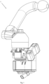
Fig. 1 shows a first embodiment of a towing hitch assembly. -
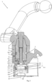
Fig. 2 shows a cross-sectional view of the towing hitch assembly also shown infig. 1 . -
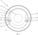
Fig. 3 shows a schematic cross-sectional view of a one-way wrap spring clutch of the towing hitch assembly. - As mentioned above, an object of the present disclosure is to mitigate inadvertent movement of a hitch arm 2 of a
tow hitch assembly 1 away from a stowed position and/or away from a deployed position. - According to an aspect, this object is achieved by a
tow hitch assembly 1. A first embodiment of thetow hitch assembly 1 is shown infigs. 1-2 . Thetow hitch assembly 1 is suitable for attachment to a vehicle, such as a truck or a car. Thetow hitch assembly 1 comprises a hitch arm 2, ahousing 3 attachable to the vehicle, and anactuator assembly 4 attached to thehousing 3. The hitch arm 2 is attached to afirst shaft 5 rotatably supported in a cylindrical cavity of a support means 6 for rotation about a first rotational axis A. The support means 6 is attached to, or integrated with, thehousing 3. Thefirst shaft 5 is axially movable relatively the support means 6 along the first rotational axis A. One of saidfirst shaft 5 and the support means 6 is provided with ahelical guide groove 7 extending around the first rotational axis A, and the other one of saidfirst shaft 5 and thesupport member 6 is provided with afirst protrusion 16 slidably engaging theguide grove 7. The sliding engagement is such that axial movement of thefirst shaft 5 brings about a rotational movement of thefirst shaft 5, said rotational movement being controlled by theguide groove 7. Thefirst shaft 5 is provided with a threadedcentral recess 8 aligned with the first rotational axis A. As will be described below, the thread of the central recess enables movement of thefirst shaft 5 along the first rotational axis A. - The
tow hitch assembly 1 comprises a one-waywrap spring clutch 9. The one-waywrap spring clutch 9 comprises afirst member 10 rotatable about the first rotational axis A, and asecond member 11 rotatable about the first rotational axis A. Thefirst member 10 is operatively connected to theactuator assembly 4 such that theactuator assembly 4 is able to control rotation of thefirst member 10. The rotation could be provided by operation of an actuator which may be an electric motor comprised in theactuator assembly 4. Any suitable operative connection between theactuator assembly 4 and thefirst member 10 is feasible, such as a fixed connection between an output shaft of theactuator assembly 4 and thefirst member 10, or a gear connection between the output shaft and thefirst member 10. - The one-way
wrap spring clutch 9 is configured such that thefirst member 10 is able to drive thesecond member 11, directly or indirectly, in any rotational direction about the first rotational axis A. The one-waywrap spring clutch 9 is further configured such that awrap spring 12 of the one-waywrap spring clutch 9 prevents thesecond member 11 from driving thefirst member 10 upon rotation of thesecond member 11 in any rotational direction about the first rotational axis A. - Any suitable one-way wrap spring clutch design could be used as long it provides this functionality. One-way wrap spring clutches are as such known in the art. Typically, a wrap spring clutch comprises a helical coil extending along a rotational axis. When the helical coil is exerted to a torque about the rotational axis, the helical coil either expands or contracts, depending on the direction of the applied torque. The expansion or contraction may be utilized to enable the helical coil to frictionally engage a shaft inside the helical coil upon contraction, or to frictionally engage a cylindrical surface around the helical coil, upon expansion of the helical coil.
- In the embodiment shown in
figs. 2 and3 , the helical coil/wrap spring 12 is able to frictionally engage the surroundingcylindrical cavity 17 of thehousing 3, thereby preventing further rotation of thewrap spring 12. - The
second member 11 of the clutch 9 is attached to, or comprises, adrive shaft 13, or is connected to thedrive shaft 13 via mechanical attachment means 14 adapted to prevent relative rotation between thesecond member 11 and thedrive shaft 13. For example, the mechanical attachment means 14 could comprise cooperating splines provided on thesecond member 11 and on thedrive shaft 13, respectively. - The
drive shaft 13 is provided with anouter thread 15 cooperating with the threads of the threadedcentral recess 8 of thefirst shaft 5. - Rotation of the
second member 11 causes rotation of thedrive shaft 13 and vice versa. Rotation of thedrive shaft 13 controls axial displacement along the first rotational axis A of thefirst shaft 5 to which the hitch arm 2 is attached. The engagement between thefirst protrusion 16 and thehelical guide groove 7 prevents thefirst shaft 5 from co-rotating with thedrive shaft 13 and controls rotation of thefirst shaft 5 as a function of an axial position of thedrive shaft 13 relatively the support means 6. By providing thesecond member 11 of the one-waywrap spring clutch 9 axially aligned with thedrive shaft 13 and connected to thedrive shaft 13 such that thesecond member 11 rotates together with thedrive shaft 13, a robust mechanism for controlling movement of the hitch arm 2 is achieved without gears, thus providing a locking mechanism with little to no play and low risk of failure. - The
wrap spring 12 is, at least partly, provided within acylindrical cavity 17 of thehousing 3. A first end portion of saidwrap spring 12 is provided with asecond protrusion 18, and a second end portion of saidwrap spring 12 is provided with athird protrusion 19. - The
first member 10 is adapted to engage the second 18 and third 19 protrusions of thewrap spring 12 with a rotational play. - In this embodiment, the
first member 10 is provided with afirst pin 20 for engaging thesecond protrusion 18, and with asecond pin 21 extending through thewrap spring 12 for engaging thethird protrusion 19, as shown infigs. 2 and3 . The engagement is such that thefirst member 10 is able to rotate thewrap spring 12 within thehousing 3 without locking thewrap spring 12 to thehousing 3. - The
second member 11 is adapted to engage the second 18 and third 19 protrusions of thewrap spring 12 with a rotational play, said engagement between thesecond member 11 and the second 18 and third 19 protrusions being such that thesecond member 11 expands thewrap spring 12 upon forced rotation of thesecond member 11 caused by rotation of thedrive shaft 13, thereby locking thewrap spring 12 to thehousing 3. Upon forced rotation of thesecond member 11 caused by rotation of thedrive shaft 13, thesecond member 11 will first move relatively thewrap spring 12 to consume any rotational play between thesecond member 11 and thewrap spring 12, and then thesecond member 11 will gradually expand thewrap spring 12 by additional rotation of thesecond member 11 until thewrap spring 12 is prevented from further expansion by the surrounding wall of thehousing 3. During expansion of thewrap spring 12, friction between thewrap spring 12 and thecylindrical cavity 17 prevents rotation of thewrap spring 12. Depending on, for example, the dimension of the wrap spring and the fit betweenwrap spring 12 and housing, the amount of the additional rotation required by thesecond member 11 varies within a predetermined angular range. An appropriate amount of rotational play is provided between thefirst member 10 and thewrap spring 12, thereby allowing thefirst member 10 to rotate together with thesecond member 11 without thefirst member 10 forcing the other end of the wrap spring 12 (i.e., the end not engaged by the second member 11) to also rotate. - Typically, the rotational play between the
second member 11 and thewrap spring 12 is chosen large enough to ensure that thewrap spring 12 does not lock when being driven by thefirst member 10. - Hence, when the
first member 10 drives one of the second 18 or third 19 protrusions of thewrap spring 12, thewrap spring 12 is brought to rotate without being forced to radially expand, thus without frictionally locking the wrap spring to thehousing 3. In fact, thewrap spring 12 may contract slightly when being driven by thefirst member 10. However, when thesecond member 11 drives one of the second 18 or third 19 protrusions of thewrap spring 12, thewrap spring 12 is being forced to radially expand and therefore frictionally engages thecylindrical cavity 17 of the housing such that the wrap spring is prevented from rotating. - The
wrap spring clutch 9 provides a compact and robust one-way clutch functionality. - The first 18 and second 19 protrusions of the
wrap spring 12 extend radially inwards with respect to the first rotational axis A. - By extending the first 18 and second 19 protrusions radially inwards, with respect to the first rotational axis A, the first 10 and second 11 members of the clutch 9 are able to engage the
wrap spring 12 through thewrap spring 12, thereby enabling a smaller footprint of the one-waywrap spring clutch 9. - In other embodiments, the first and second protrusions may alternatively extend in any other suitable way, rather than radially inwards; For example, parallel to the first rotational axis A, or radially outwards with respect to the first rotational axis A.
- In other embodiments, any other suitable one-way wrap spring clutch design could alternatively be used instead.
- The actuator assembly comprises an actuator comprising an electric motor. In other embodiments, the actuator may comprise any other suitable motor, such as a hydraulically powered motor.
- The wrap spring comprises a coil spring or wound coil extending along the first rotational axis A, as indicated in
figs. 2 and3 .Table of reference numerals 1 tow hitch assembly 2 hitch arm 3 housing 4 actuator assembly 5 first shaft 6 support means 7 helical guide groove 8 threaded central recess 9 one-way wrap spring clutch 10 first member of clutch 11 second member of clutch 12 wrap spring 13 drive shaft 14 mechanical attachment means between second member and drive shaft 15 outer thread of drive shaft A first rotational axis 16 first protrusion 17 cylindrical cavity of housing 18 second protrusion 19 third protrusion 20 first pin of first member 21 second pin of first member
Claims (6)
- A tow hitch assembly (1) for attachment to a vehicle, said tow hitch assembly (1) comprising a hitch arm (2), a housing (3) attachable to the vehicle, and an actuator assembly (4) attached to the housing (3),said hitch arm (2) being attached to a first shaft (5) rotatably supported in a cylindrical cavity of a support means (6) attached to, or integrated with, the housing (3) for rotation about a first rotational axis (A),said tow hitch assembly (1) further comprising a one-way wrap spring clutch (9),said one-way wrap spring clutch (9) comprising a first member (10) rotatable about the first rotational axis (A), and a second member (11) rotatable about the first rotational axis (A),said first member (10) being operatively connected to the actuator assembly (4) such that the actuator assembly (4) is able to control rotation of the first member (10),said one-way wrap spring clutch (9) being configured such that the first member (10) is able to drive the second member (11) in any rotational direction about the first rotational axis (A), and such that a wrap spring (12) of the one-way wrap spring clutch (9) prevents the second member (11) from driving the first member (10) upon rotation of the second member (11) in any rotational direction about the first rotational axis (A),wherein the second member (11) is operatively connected to the first shaft.
- A tow hitch assembly (1) according to claim 1, wherein the first shaft (5) is axially movable relatively the support means (6) along the first rotational axis (A),one of said first shaft (5) and the support means (6) being provided with a helical guide groove (7) extending around the first rotational axis (A), and the other one of said first shaft (5) and the support member (6) being provided with a first protrusion (16) slidably engaging the guide grove (7) such that axial movement of the first shaft (5) brings about a rotational movement of the first shaft (5), said rotational movement being controlled by the helical guide groove (7),said first shaft (5) being provided with a threaded central recess (8) aligned with the first rotational axis (A),wherein the second member (11) is attached to a drive shaft (13), or comprises the drive shaft (13), or is connected to the drive shaft (13) via mechanical attachment means (14) adapted to prevent relative rotation between the second member (11) and the drive shaft (13),wherein the drive shaft (13) is provided with an outer thread (15) cooperating with the threads of the threaded central recess (8) of the first shaft (5).
- A tow hitch assembly (1) according to any one of claims 1-2, wherein the wrap spring (12) is, at least partly, provided within a cylindrical cavity (17) of the housing (3),a first end portion of said wrap spring (12) being provided with a second protrusion (18), and a second end portion of said wrap spring (12) being provided with a third protrusion (19),wherein the first member (10) is adapted to engage the second (18) and third (19) protrusions of the wrap spring (12) with a rotational play, said engagement being such that the first member (10) is able to rotate the wrap spring (12) within the housing (3) without locking the wrap spring (12) to the housing (3), andwherein the second member (11) is adapted to engage the second (18) and third (19) protrusions of the wrap spring (12) with a rotational play, said engagement between the second member (11) and the second (18) and third (19) protrusions being such that the second member (11) expands the wrap spring (12) upon forced rotation of the second member (11) caused by rotation of the first shaft (5), thereby locking the wrap spring (12) to the housing (3).
- A tow hitch assembly (1) according to claim 3, wherein the first (18) and second (19) protrusions of the wrap spring (12) extend radially inwards with respect to the first rotational axis (A).
- A tow hitch assembly (1) according to any one of claims 1-4, wherein the actuator assembly comprises an actuator comprising an electric motor.
- A tow hitch assembly (1) according to any one of claims 1-5, wherein the wrap spring comprises a coil spring or wound coil.
Priority Applications (2)
| Application Number | Priority Date | Filing Date | Title |
|---|---|---|---|
| EP23160580.9A EP4427951B1 (en) | 2023-03-07 | 2023-03-07 | Tow hitch assembly comprising a one-way wrap spring clutch |
| PCT/EP2024/055538 WO2024184289A1 (en) | 2023-03-07 | 2024-03-04 | Tow hitch assembly comprising a one-way wrap spring clutch |
Applications Claiming Priority (1)
| Application Number | Priority Date | Filing Date | Title |
|---|---|---|---|
| EP23160580.9A EP4427951B1 (en) | 2023-03-07 | 2023-03-07 | Tow hitch assembly comprising a one-way wrap spring clutch |
Publications (2)
| Publication Number | Publication Date |
|---|---|
| EP4427951A1 true EP4427951A1 (en) | 2024-09-11 |
| EP4427951B1 EP4427951B1 (en) | 2025-05-21 |
Family
ID=85511256
Family Applications (1)
| Application Number | Title | Priority Date | Filing Date |
|---|---|---|---|
| EP23160580.9A Active EP4427951B1 (en) | 2023-03-07 | 2023-03-07 | Tow hitch assembly comprising a one-way wrap spring clutch |
Country Status (2)
| Country | Link |
|---|---|
| EP (1) | EP4427951B1 (en) |
| WO (1) | WO2024184289A1 (en) |
Citations (7)
| Publication number | Priority date | Publication date | Assignee | Title |
|---|---|---|---|---|
| EP2546539A2 (en) * | 2008-11-17 | 2013-01-16 | Litens Automotive Partnership | A helical coil clutch assembly comprising an actuator to effect engagement of helical coil clutch with a clutch surface |
| EP2671737A2 (en) * | 2012-06-04 | 2013-12-11 | WESTFALIA - Automotive GmbH | Drive device for a ball neck of a trailer coupling |
| DE102017010409A1 (en) * | 2017-11-09 | 2019-05-09 | Audi Ag | Towbar for a vehicle |
| EP3571066A1 (en) * | 2017-01-20 | 2019-11-27 | Vapos Spol. S.r.o. | Automatic hinged towing device especially for passenger cars |
| US20210370731A1 (en) * | 2020-05-27 | 2021-12-02 | ACPS Automotive GmbH | Trailer device |
| DE102021116182A1 (en) * | 2021-06-23 | 2022-12-29 | Mvg-Metallverarbeitungsgesellschaft Mbh | Hitch for attachment to the rear of a vehicle |
| EP4124476A1 (en) * | 2021-07-26 | 2023-02-01 | Zhejiang Zhiyou Automotive Technology Co., Ltd. | Manual and electric dual-mode trailer hitching apparatus |
-
2023
- 2023-03-07 EP EP23160580.9A patent/EP4427951B1/en active Active
-
2024
- 2024-03-04 WO PCT/EP2024/055538 patent/WO2024184289A1/en not_active Ceased
Patent Citations (7)
| Publication number | Priority date | Publication date | Assignee | Title |
|---|---|---|---|---|
| EP2546539A2 (en) * | 2008-11-17 | 2013-01-16 | Litens Automotive Partnership | A helical coil clutch assembly comprising an actuator to effect engagement of helical coil clutch with a clutch surface |
| EP2671737A2 (en) * | 2012-06-04 | 2013-12-11 | WESTFALIA - Automotive GmbH | Drive device for a ball neck of a trailer coupling |
| EP3571066A1 (en) * | 2017-01-20 | 2019-11-27 | Vapos Spol. S.r.o. | Automatic hinged towing device especially for passenger cars |
| DE102017010409A1 (en) * | 2017-11-09 | 2019-05-09 | Audi Ag | Towbar for a vehicle |
| US20210370731A1 (en) * | 2020-05-27 | 2021-12-02 | ACPS Automotive GmbH | Trailer device |
| DE102021116182A1 (en) * | 2021-06-23 | 2022-12-29 | Mvg-Metallverarbeitungsgesellschaft Mbh | Hitch for attachment to the rear of a vehicle |
| EP4124476A1 (en) * | 2021-07-26 | 2023-02-01 | Zhejiang Zhiyou Automotive Technology Co., Ltd. | Manual and electric dual-mode trailer hitching apparatus |
Also Published As
| Publication number | Publication date |
|---|---|
| EP4427951B1 (en) | 2025-05-21 |
| WO2024184289A1 (en) | 2024-09-12 |
Similar Documents
| Publication | Publication Date | Title |
|---|---|---|
| US8943916B2 (en) | Chassis actuator | |
| JP3559096B2 (en) | Linear actuator | |
| US7634951B2 (en) | Spindle drive for a movable component, the spindle drive being drivable by a drive | |
| US10234028B2 (en) | Shift by wire transmission shift control system | |
| US7891261B2 (en) | Clutch actuation system with locking mechanism and method of controlling engagement of a clutch | |
| US10598280B2 (en) | Actuation unit for controlling the angular position of a control member, particularly for a vehicle transmission | |
| US5482255A (en) | Winch having heat dissipating braking | |
| WO2012124812A1 (en) | Electric braking device with parking mechanism | |
| JP2016538487A (en) | Group comprising a friction device | |
| US10889282B2 (en) | Vehicle brake device | |
| CN108027059B (en) | Rotary actuator | |
| US12196280B2 (en) | Actuation device for an electromechanically actuatable motor vehicle brake | |
| US12078228B2 (en) | Screw drive with self-locking mechanism | |
| US20230151862A1 (en) | Actuator assembly for a vehicle brake | |
| JP2004190859A (en) | Position compensation differential lock mechanism | |
| EP4427951A1 (en) | Tow hitch assembly comprising a one-way wrap spring clutch | |
| WO2017129610A2 (en) | Clutch actuator for a vehicle | |
| US6851533B2 (en) | Spring brake actuator | |
| JP4127286B2 (en) | Parking lock device for transmission | |
| US20250035176A1 (en) | Brake actuator and vehicle brake | |
| US6889801B2 (en) | Transmission brake | |
| EP3045776A1 (en) | Failsafe electrical actuator for a differential locking system | |
| JP5099075B2 (en) | Clutch device | |
| US12429136B2 (en) | Parking lock system for a vehicle transmission | |
| JP2007085544A (en) | Parking brake for vehicles with automatic locking device |
Legal Events
| Date | Code | Title | Description |
|---|---|---|---|
| PUAI | Public reference made under article 153(3) epc to a published international application that has entered the european phase |
Free format text: ORIGINAL CODE: 0009012 |
|
| STAA | Information on the status of an ep patent application or granted ep patent |
Free format text: STATUS: REQUEST FOR EXAMINATION WAS MADE |
|
| 17P | Request for examination filed |
Effective date: 20230915 |
|
| AK | Designated contracting states |
Kind code of ref document: A1 Designated state(s): AL AT BE BG CH CY CZ DE DK EE ES FI FR GB GR HR HU IE IS IT LI LT LU LV MC ME MK MT NL NO PL PT RO RS SE SI SK SM TR |
|
| GRAP | Despatch of communication of intention to grant a patent |
Free format text: ORIGINAL CODE: EPIDOSNIGR1 |
|
| STAA | Information on the status of an ep patent application or granted ep patent |
Free format text: STATUS: GRANT OF PATENT IS INTENDED |
|
| INTG | Intention to grant announced |
Effective date: 20241202 |
|
| GRAJ | Information related to disapproval of communication of intention to grant by the applicant or resumption of examination proceedings by the epo deleted |
Free format text: ORIGINAL CODE: EPIDOSDIGR1 |
|
| STAA | Information on the status of an ep patent application or granted ep patent |
Free format text: STATUS: REQUEST FOR EXAMINATION WAS MADE |
|
| INTC | Intention to grant announced (deleted) | ||
| GRAP | Despatch of communication of intention to grant a patent |
Free format text: ORIGINAL CODE: EPIDOSNIGR1 |
|
| STAA | Information on the status of an ep patent application or granted ep patent |
Free format text: STATUS: GRANT OF PATENT IS INTENDED |
|
| INTG | Intention to grant announced |
Effective date: 20250303 |
|
| GRAS | Grant fee paid |
Free format text: ORIGINAL CODE: EPIDOSNIGR3 |
|
| GRAA | (expected) grant |
Free format text: ORIGINAL CODE: 0009210 |
|
| STAA | Information on the status of an ep patent application or granted ep patent |
Free format text: STATUS: THE PATENT HAS BEEN GRANTED |
|
| AK | Designated contracting states |
Kind code of ref document: B1 Designated state(s): AL AT BE BG CH CY CZ DE DK EE ES FI FR GB GR HR HU IE IS IT LI LT LU LV MC ME MK MT NL NO PL PT RO RS SE SI SK SM TR |
|
| REG | Reference to a national code |
Ref country code: GB Ref legal event code: FG4D |
|
| REG | Reference to a national code |
Ref country code: CH Ref legal event code: EP |
|
| REG | Reference to a national code |
Ref country code: DE Ref legal event code: R096 Ref document number: 602023003550 Country of ref document: DE |
|
| REG | Reference to a national code |
Ref country code: IE Ref legal event code: FG4D |
|
| P01 | Opt-out of the competence of the unified patent court (upc) registered |
Free format text: CASE NUMBER: APP_23424/2025 Effective date: 20250516 |
|
| REG | Reference to a national code |
Ref country code: NL Ref legal event code: FP |
|
| PG25 | Lapsed in a contracting state [announced via postgrant information from national office to epo] |
Ref country code: PT Free format text: LAPSE BECAUSE OF FAILURE TO SUBMIT A TRANSLATION OF THE DESCRIPTION OR TO PAY THE FEE WITHIN THE PRESCRIBED TIME-LIMIT Effective date: 20250922 Ref country code: ES Free format text: LAPSE BECAUSE OF FAILURE TO SUBMIT A TRANSLATION OF THE DESCRIPTION OR TO PAY THE FEE WITHIN THE PRESCRIBED TIME-LIMIT Effective date: 20250521 Ref country code: FI Free format text: LAPSE BECAUSE OF FAILURE TO SUBMIT A TRANSLATION OF THE DESCRIPTION OR TO PAY THE FEE WITHIN THE PRESCRIBED TIME-LIMIT Effective date: 20250521 |
|
| REG | Reference to a national code |
Ref country code: LT Ref legal event code: MG9D |
|
| PG25 | Lapsed in a contracting state [announced via postgrant information from national office to epo] |
Ref country code: NO Free format text: LAPSE BECAUSE OF FAILURE TO SUBMIT A TRANSLATION OF THE DESCRIPTION OR TO PAY THE FEE WITHIN THE PRESCRIBED TIME-LIMIT Effective date: 20250821 Ref country code: GR Free format text: LAPSE BECAUSE OF FAILURE TO SUBMIT A TRANSLATION OF THE DESCRIPTION OR TO PAY THE FEE WITHIN THE PRESCRIBED TIME-LIMIT Effective date: 20250822 |
|
| PG25 | Lapsed in a contracting state [announced via postgrant information from national office to epo] |
Ref country code: PL Free format text: LAPSE BECAUSE OF FAILURE TO SUBMIT A TRANSLATION OF THE DESCRIPTION OR TO PAY THE FEE WITHIN THE PRESCRIBED TIME-LIMIT Effective date: 20250521 |
|
| PG25 | Lapsed in a contracting state [announced via postgrant information from national office to epo] |
Ref country code: BG Free format text: LAPSE BECAUSE OF FAILURE TO SUBMIT A TRANSLATION OF THE DESCRIPTION OR TO PAY THE FEE WITHIN THE PRESCRIBED TIME-LIMIT Effective date: 20250521 |
|
| PG25 | Lapsed in a contracting state [announced via postgrant information from national office to epo] |
Ref country code: HR Free format text: LAPSE BECAUSE OF FAILURE TO SUBMIT A TRANSLATION OF THE DESCRIPTION OR TO PAY THE FEE WITHIN THE PRESCRIBED TIME-LIMIT Effective date: 20250521 |
|
| PG25 | Lapsed in a contracting state [announced via postgrant information from national office to epo] |
Ref country code: RS Free format text: LAPSE BECAUSE OF FAILURE TO SUBMIT A TRANSLATION OF THE DESCRIPTION OR TO PAY THE FEE WITHIN THE PRESCRIBED TIME-LIMIT Effective date: 20250821 |
|
| PG25 | Lapsed in a contracting state [announced via postgrant information from national office to epo] |
Ref country code: IS Free format text: LAPSE BECAUSE OF FAILURE TO SUBMIT A TRANSLATION OF THE DESCRIPTION OR TO PAY THE FEE WITHIN THE PRESCRIBED TIME-LIMIT Effective date: 20250921 |
|
| PG25 | Lapsed in a contracting state [announced via postgrant information from national office to epo] |
Ref country code: LV Free format text: LAPSE BECAUSE OF FAILURE TO SUBMIT A TRANSLATION OF THE DESCRIPTION OR TO PAY THE FEE WITHIN THE PRESCRIBED TIME-LIMIT Effective date: 20250521 |
|
| REG | Reference to a national code |
Ref country code: AT Ref legal event code: MK05 Ref document number: 1796478 Country of ref document: AT Kind code of ref document: T Effective date: 20250521 |
|
| PG25 | Lapsed in a contracting state [announced via postgrant information from national office to epo] |
Ref country code: DK Free format text: LAPSE BECAUSE OF FAILURE TO SUBMIT A TRANSLATION OF THE DESCRIPTION OR TO PAY THE FEE WITHIN THE PRESCRIBED TIME-LIMIT Effective date: 20250521 Ref country code: AT Free format text: LAPSE BECAUSE OF FAILURE TO SUBMIT A TRANSLATION OF THE DESCRIPTION OR TO PAY THE FEE WITHIN THE PRESCRIBED TIME-LIMIT Effective date: 20250521 Ref country code: SM Free format text: LAPSE BECAUSE OF FAILURE TO SUBMIT A TRANSLATION OF THE DESCRIPTION OR TO PAY THE FEE WITHIN THE PRESCRIBED TIME-LIMIT Effective date: 20250521 |
|
| PG25 | Lapsed in a contracting state [announced via postgrant information from national office to epo] |
Ref country code: CZ Free format text: LAPSE BECAUSE OF FAILURE TO SUBMIT A TRANSLATION OF THE DESCRIPTION OR TO PAY THE FEE WITHIN THE PRESCRIBED TIME-LIMIT Effective date: 20250521 |
|
| PG25 | Lapsed in a contracting state [announced via postgrant information from national office to epo] |
Ref country code: EE Free format text: LAPSE BECAUSE OF FAILURE TO SUBMIT A TRANSLATION OF THE DESCRIPTION OR TO PAY THE FEE WITHIN THE PRESCRIBED TIME-LIMIT Effective date: 20250521 |
|
| PG25 | Lapsed in a contracting state [announced via postgrant information from national office to epo] |
Ref country code: SK Free format text: LAPSE BECAUSE OF FAILURE TO SUBMIT A TRANSLATION OF THE DESCRIPTION OR TO PAY THE FEE WITHIN THE PRESCRIBED TIME-LIMIT Effective date: 20250521 |
|
| PG25 | Lapsed in a contracting state [announced via postgrant information from national office to epo] |
Ref country code: IT Free format text: LAPSE BECAUSE OF FAILURE TO SUBMIT A TRANSLATION OF THE DESCRIPTION OR TO PAY THE FEE WITHIN THE PRESCRIBED TIME-LIMIT Effective date: 20250521 |
|
| REG | Reference to a national code |
Ref country code: DE Ref legal event code: R097 Ref document number: 602023003550 Country of ref document: DE |
|
| PLBE | No opposition filed within time limit |
Free format text: ORIGINAL CODE: 0009261 |
|
| STAA | Information on the status of an ep patent application or granted ep patent |
Free format text: STATUS: NO OPPOSITION FILED WITHIN TIME LIMIT |
|
| REG | Reference to a national code |
Ref country code: CH Ref legal event code: L10 Free format text: ST27 STATUS EVENT CODE: U-0-0-L10-L00 (AS PROVIDED BY THE NATIONAL OFFICE) Effective date: 20260402 |
|
| PGFP | Annual fee paid to national office [announced via postgrant information from national office to epo] |
Ref country code: DE Payment date: 20260309 Year of fee payment: 4 |
|
| PGFP | Annual fee paid to national office [announced via postgrant information from national office to epo] |
Ref country code: NL Payment date: 20260310 Year of fee payment: 4 |
|
| PGFP | Annual fee paid to national office [announced via postgrant information from national office to epo] |
Ref country code: FR Payment date: 20260312 Year of fee payment: 4 |
|
| 26N | No opposition filed |
Effective date: 20260224 |