EP4427888A2 - Power tool to tool bit extension adapter - Google Patents
Power tool to tool bit extension adapter Download PDFInfo
- Publication number
- EP4427888A2 EP4427888A2 EP24190992.8A EP24190992A EP4427888A2 EP 4427888 A2 EP4427888 A2 EP 4427888A2 EP 24190992 A EP24190992 A EP 24190992A EP 4427888 A2 EP4427888 A2 EP 4427888A2
- Authority
- EP
- European Patent Office
- Prior art keywords
- tool bit
- adapter
- extension adapter
- collar
- extension
- Prior art date
- Legal status (The legal status is an assumption and is not a legal conclusion. Google has not performed a legal analysis and makes no representation as to the accuracy of the status listed.)
- Granted
Links
Images


Classifications
-
- B—PERFORMING OPERATIONS; TRANSPORTING
- B25—HAND TOOLS; PORTABLE POWER-DRIVEN TOOLS; MANIPULATORS
- B25B—TOOLS OR BENCH DEVICES NOT OTHERWISE PROVIDED FOR, FOR FASTENING, CONNECTING, DISENGAGING, OR HOLDING
- B25B23/00—Details of, or accessories for, spanners, wrenches, screwdrivers
- B25B23/0007—Connections or joints between tool parts
- B25B23/0021—Prolongations interposed between handle and tool
-
- B—PERFORMING OPERATIONS; TRANSPORTING
- B23—MACHINE TOOLS; METAL-WORKING NOT OTHERWISE PROVIDED FOR
- B23B—TURNING; BORING
- B23B31/00—Chucks; Expansion mandrels; Adaptations thereof for remote control
- B23B31/02—Chucks
- B23B31/10—Chucks characterised by the retaining or gripping devices or their immediate operating means
- B23B31/107—Retention by laterally-acting detents, e.g. pins, screws, wedges; Retention by loose elements, e.g. balls
- B23B31/1071—Retention by balls
-
- B—PERFORMING OPERATIONS; TRANSPORTING
- B25—HAND TOOLS; PORTABLE POWER-DRIVEN TOOLS; MANIPULATORS
- B25B—TOOLS OR BENCH DEVICES NOT OTHERWISE PROVIDED FOR, FOR FASTENING, CONNECTING, DISENGAGING, OR HOLDING
- B25B23/00—Details of, or accessories for, spanners, wrenches, screwdrivers
- B25B23/0007—Connections or joints between tool parts
- B25B23/0035—Connection means between socket or screwdriver bit and tool
-
- B—PERFORMING OPERATIONS; TRANSPORTING
- B25—HAND TOOLS; PORTABLE POWER-DRIVEN TOOLS; MANIPULATORS
- B25D—PERCUSSIVE TOOLS
- B25D17/00—Details of, or accessories for, portable power-driven percussive tools
- B25D17/005—Attachments or adapters placed between tool and hammer
-
- B—PERFORMING OPERATIONS; TRANSPORTING
- B25—HAND TOOLS; PORTABLE POWER-DRIVEN TOOLS; MANIPULATORS
- B25D—PERCUSSIVE TOOLS
- B25D17/00—Details of, or accessories for, portable power-driven percussive tools
- B25D17/08—Means for retaining and guiding the tool bit, e.g. chucks allowing axial oscillation of the tool bit
- B25D17/084—Rotating chucks or sockets
- B25D17/088—Rotating chucks or sockets with radial movable locking elements co-operating with bit shafts specially adapted therefor
-
- B—PERFORMING OPERATIONS; TRANSPORTING
- B25—HAND TOOLS; PORTABLE POWER-DRIVEN TOOLS; MANIPULATORS
- B25D—PERCUSSIVE TOOLS
- B25D2217/00—Details of, or accessories for, portable power-driven percussive tools
- B25D2217/003—Details relating to chucks with radially movable locking elements
- B25D2217/0038—Locking members of special shape
- B25D2217/0042—Ball-shaped locking members
Definitions
- the present disclosure relates to extension adapters for tool bits, and more particularly to extension adapters that couple a tool bit to a power tool.
- the present disclosure provides, in another aspect, an extension adapter configured to couple a tool bit to a power tool.
- the power tool is configured to drive the extension adapter and the tool bit about a rotational axis.
- the extension adapter includes a body having an inner surface defining a bore configured to receive the tool bit.
- the bore includes a first diameter.
- the extension adapter also includes a collar moveable between an unlocked position and a locked position.
- the unlocked position is configured to allow the tool bit to be removed from the bore.
- the locked position is configured to secure the tool bit to the body.
- the extension adapter includes a maximum outer diameter. A ratio of the maximum outer diameter of the extension adapter over the first diameter of the bore is equal to or less than 2.5.
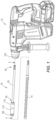
- FIG. 1 illustrates a power tool 10 selectively coupled to a tool bit 15 by an extension adapter 20.
- the power tool 10 is operable to rotate the adapter 20 and the tool bit 15 about a rotational axis 25 ( FIG. 2 ).
- the connection between the tool bit 15 and the adapter 20 and the connection between the adapter 20 and the power tool 10 is commonly referred to as a Special Direct System (SDS) plus connection.
- SDS Special Direct System
- the connection between the tool bit 15 and the adapter 20 and/or the connection between the adapter 20 and the power tool 10 can be a different type of SDS connection (e.g., SDS top connection, SDS max connection, etc.).
- the tool bit 15 can be directly coupled to the power tool 10 by omitting the adapter 20.
- the adapter 20 includes a body 30 having a rear portion 35 separated from a front portion 40 by a flange 45.
- the flange 45 extends radially from an outer surface 50 of the body 30.
- the rear portion 35 of the body 30 includes two opposing cylindrical apertures 55 (only one cylindrical aperture 55 is illustrated in FIG. 2 ).
- the cylindrical apertures 55 are spaced 180 degrees from each other and are in communication with a central bore 65 of the adapter 20 defined by an inner surface 70 of the body 30.
- the inner surface 70 defines a diameter 72 ( FIGS. 4-7 ) of about 0.394 inches (e.g., slightly larger than a shank of the tool bit 15).
- the diameter 72 can be greater than or less than about 0.394 inches.
- Each cylindrical aperture 55 is sized to receive a locking member (e.g., a ball bearing or locking sphere 75) so that a portion of each locking sphere 75 extends beyond the inner surface 70 and into the central bore 65 ( FIG. 4 ).
- a plug or protrusion can be received through each aperture 55 into the central bore 65 and fixed relative to the body 30.
- the body 30 includes two opposing protrusions 80 (e.g., anti-rotational rails) extending beyond the inner surface 70 of the central bore 35 radially toward the rotational axis 25( FIG. 4 ).
- the illustrated protrusions 80 also linearly extend from the rear portion 35 of the body 30 to the front portion 40 of the body 30.
- the protrusions 80 are formed integral with the body 30 as a single component.
- the protrusions 80 can be inserts that are coupled to the body 30 (e.g., by a press fit engagement, by a brazing process, or the like).
- the body 30 can include more than two protrusions 80 (e.g., four protrusions) with a pair of protrusions associated with the rear portion 35 of the body 30 and the other pair of protrusions associated with the front portion 40 of the body 30.
- protrusions 80 e.g., four protrusions
- the body 30 of the adapter 20 is coupled to the power tool 10 by an extension shank or shaft 85.
- the illustrated shaft 85 includes a first end portion 90 that is coupled to the body 30 and a second end portion 95 that is coupled to a chuck 100 of the power tool 10. Both end portions 90, 95 include two opposing channels 105 and two opposing grooves 110, which collectively define a SDS plus interface.
- the shaft 85 is positioned within the central bore 65 so that a portion of each protrusion 80 is received within one channel 105 of the first end portion 90 and each locking sphere 75 is received within one groove 110 of the first end portion 90 ( FIG. 4 ).
- Such a connection between the shaft 85 and the body 30 locks the shaft 85 to the body 30 and allows the shaft 85 to axially move along the rotational axis 25, but inhibits the shaft 85 from rotating relative to the body 30.
- the shaft 85 can be fixed to the body 30 (e.g., inhibited from axial and rotational movement relative to the body 30).
- the shaft 85 extends through a rear end cover 115 that is coupled to the rear portion 35 of the body 30 (e.g., by a threaded engagement between the rear portion 35 of the body 30 and the rear end cover 115).
- the rear end cover 115 extends over the two cylindrical apertures 55- and ultimately the two locking spheres 75-to trap each locking sphere 75 within the respective cylindrical aperture 55 between the respective groove 110 and the rear end cover 115 ( FIG. 4 ).
- a gasket 120 is positioned within a slot 122 formed between the rear portion 35 and a portion of the rear end cover 115.
- the gasket 120 inhibits dust and debris from entering the adapter 20 through the central bore 65 between the shaft 85 and the rear end cover 115.
- the gasket 120 can be composed of an elastomeric or rubber material.
- the gasket 120 can be a wiper ring-type gasket, a quad ring gasket, an O-ring gasket, etc. In other embodiments, the gasket 120 can be omitted.
- the front portion 40 includes one elongated aperture 125 (in a direction parallel to the rotational axis 25) spaced 90 degrees relative to the protrusions 80.
- the elongated aperture 125 includes a forward end 130 and a rearward end 135 with the rearward end 135 positioned closer to the rear portion 35 of the body 30 than the forward end 130.
- the elongated aperture 125 is sized to receive a retaining member (e.g., a ball bearing or retaining sphere 140).
- the elongated aperture 125 includes an open floor 145 in which a portion of the retaining sphere 140 extends through to extend into the central bore 65.
- the retaining sphere 140 extends into the central bore 65 ( FIGS. 4 and 6 ). In other embodiments, about 2 mm of the retaining sphere 140 extends into the central bore 65. In further embodiments, about 1.5 mm to about 2 mm of the retaining sphere 140 extends into the central bore 65.
- the illustrated retaining sphere 140 includes a major dimension (e.g., diameter 150; FIG. 2 ) of about 4.5 mm. In other embodiments, the diameter 150 of the retaining sphere 140 can be less than about 7 mm. In further embodiments, the diameter 150 of the retaining sphere 140 can be between about 4.5 mm and about 7 mm. In yet further embodiments, the diameter 150 of the retaining sphere 140 can be less than 4.5 mm.
- a first biasing member (e.g., a first compression coil spring 155) surrounds the front portion 40 of the body 30 with one side of the first spring 155 contacting the flange 45 and the other side of the first spring 155 having a radially inward extending protrusion 160.
- the protrusion 160 is sized to be received within the elongated aperture 125 to engage the retaining sphere 140 and bias the retaining sphere 140 toward the forward end 130 of the elongated aperture 125 (e.g., away from the shaft 85).
- the illustrated protrusion 160 is a U-shaped protrusion formed away from one end 165 of the first spring 155.
- the end 165 of the first spring 155 can form at least a portion of the protrusion 160.
- the protrusion 160 can be a loop or a V-shaped protrusion.
- the adapter 20 also includes a collar 170 slidably coupled to the front portion 40 of the body 30.
- the illustrated collar 170 includes an outer diameter 175 of about 0.827 inches, which is substantially the same as an outer diameter of the rear end cover 115.
- a ratio of the outer diameter 175 over the diameter 72 of the central bore 65 is about 2.1.
- the outer diameter 175 is less than about 0.875 inches so that a ratio of the outer diameter 175 over the diameter 72 of the central bore 65 is less than about 2.1.
- the outer diameter 175 is less than about 0.75 inches so that a ratio of the outer diameter 175 over the diameter 72 of the central bore 65 is less than about 1.9.
- a maximum width of the adapter 20 is less than about 0.875 inches or less than about 0.75 inches.
- a ratio of the maximum width of the adapter 20 (e.g., the outer diameter 175) over the major dimension 150 of the retaining member 140 (both measured in inches) is about 4.7. In other embodiments, the ratio of the maximum width of the adapter 20 over the major dimension 150 of the retaining member 140 can be less than 4.7.
- the illustrated collar 170 includes a step 180 extending around an inner surface of the collar 170 with the step 180 including an obliquely angled surface 185 (relative to the rotational axis 25) and an inner surface 188.
- the angled surface 185 generally faces toward the rear portion 35 of the body 30.
- the illustrated first spring 155 is positioned between the flange 45 and the step 180.
- a second biasing member e.g., a second compression coil spring 190
- the front end cover 195 is coupled to the front portion 40 of the body 30 (e.g., by a threaded engagement between the front portion 40 of the body 30 and the front end cover 195).
- the second spring 190 engages the step 180 to bias the collar 170 away from the front end cover 195 (e.g., toward the shaft 85).
- the adapter 20 includes a gasket 200 positioned within a slot 204 formed between the front portion 40 and a portion of the front end cover 195.
- the gasket 200 inhibits dust and debris from entering the adapter 20 through the central bore 65 when the tool bit 15 is coupled to the adapter 20 ( FIG. 6 ).
- the gasket 200 can be composed of an elastomeric or rubber material.
- the gasket 200 can be a wiper ring-type gasket, a quad ring gasket, an O-ring gasket, etc. In other embodiments, the gasket 200 can be omitted.
- a dust cover or shield can be coupled to an outer surface of the front end cover 195 to divert dust and debris away from a front interface (e.g., a gap 202) between the front end cover 195 and the collar 170. As such, dust and debris are inhibited from entering into the adapter 20 through the gap 202 between the collar 170 and the front portion 40 of the body 30.
- the dust cover can include an outer diameter that is equal to or smaller than the maximum outer diameter of the adapter 20.
- the front end cover 195 and the dust cover can be formed as a single integral component.
- the tool bit 15 is coupled to the adapter 20 without the use of a tool, and the tool bit 15 can be automatically locked to the adapter 20 without moving the collar 170 relative to the body 30.
- the tool bit 15 is inserted into the central bore 65 through the front end cover 195 and the gasket 200 so that a portion of the protrusions 80 are received within channels of the tool bit 15 (similar to the channels 105 of the shaft 85).
- a rear surface 205 of the tool bit 15 contacts the retaining sphere 140, and the tool bit 15 pushes the retaining sphere 140 off of the inner surface 188 of the step 180 toward the rearward end 135 of the elongated aperture 125 against the biasing force of the first spring 155.
- the retaining sphere 140 can then slide along the angled surface 185 of the step 180 toward the rearward end 135. Once the tool bit 15 pushes the retaining sphere 140 into engagement with the rearward end 135, the retaining sphere 140 then moves radially toward the collar 170 to provide enough clearance between the tool bit 15 and the retaining sphere 140 for the tool bit 15 to be fully inserted into the central bore 65.
- the tool bit 15 pushes the retaining sphere 140 radially outward so that no portion of the retaining sphere 140 extends into the central bore 65, thereby allowing the tool bit 15 to be fully inserted into the central bore 65.
- the first spring 155 then pushes the retaining sphere 140 against the angled surface 185 for the retaining sphere 140 to slide radially inward into the central bore 65 to be received into a groove of the tool bit 15 (similar to the groove 110 of the shaft 85).
- the retaining sphere 140 retains the tool bit 15 within the adapter 20 ( FIG. 6 ), but allows for some axial movement of the tool bit 15 along the rotational axis 25.
- the power tool 10 is operable to drive the tool bit 15 into a workpiece (e.g., concrete, brick, or the like) to form a hole.
- a workpiece e.g., concrete, brick, or the like
- the tool bit 15 and the adapter 20 can move into the hole being formed in the workpiece if the diameter of the tool bit 15 is greater than the maximum width of the adapter 20 (e.g., greater than 0.875 inches).
- a tool bit 15 having a diameter greater than the outer diameter 175 of the adapter 20 e.g., 0.875 inches
- a 6 inch long tool bit 15 having a diameter of at least 0.875 inches can be used to bore a hole that is longer than 6 inches by using the adapter 20.
- the tool bit 15 can be removed from the adapter 20 by moving the collar 170 toward the front end cover 195 ( FIG. 7 ).
- the step 180 moves in a position between the elongated aperture 125 and the front end cover 195 to allow the retaining sphere 140 to move radially out of the central bore 65 as the tool bit 15 slides out of the adapter 20.
- the second spring 190 automatically biases the collar 170 toward the shaft 85 to position the step 180 over the elongated aperture 125 as the retaining sphere 140 slides along the angled surface 185 into engagement with the inner surface 188 of the step 180.
- the collar 170 can move toward the rear end cover 115 to release the tool bit 15 from the adapter 20.
- FIGS. 8-11 illustrate an adapter 320 ( FIG. 8 ) according to another embodiment of the disclosure.
- the adapter 320 is similar to the adapter 20; therefore, like components have been given like references numbers plus 300. At least some differences and/or at least some similarities between the adapters 20, 320 will be discussed in detail below. In addition, components or features described with respect to the adapter 320 are equally applicable to the adapter 20.
- the adapter 320 includes a body 330 having an inner surface 370 defining a central bore 365 having a diameter 372.
- the body 330 also includes an outer surface 350 and a rear portion 335 separated from a front portion 340 by a flange 345.
- the adapter 320 defines a rotational axis 325.
- the rear portion 335 is longer than the front portion 340, and the front portion 340 includes a larger diameter than the flange 345 and the rear portion 335.
- the rear portion 335 includes a first pair of opposing cylindrical apertures 355a (only one cylindrical aperture 355a is illustrated in FIG.
- Each cylindrical aperture 355a is sized to receive a locking member (e.g., a locking sphere 375).
- the adapter 320 also includes an extension shank or shaft 385.
- the illustrated shaft 385 includes a first end portion 390 coupled to the body 330 and a second end portion 395 coupled to the chuck 100 of the power tool 10.
- Both end portions 390, 395 include two opposing channels 405 and two opposing grooves 410 (e.g., a SDS plus interface).
- a rear end cover 415 is coupled to the rear portion 335 of the body 330 (e.g., by a retaining ring) to extend over the two cylindrical apertures 355a. As such, each locking sphere 375 is trapped within the respective cylindrical aperture 355a between the respective groove 410 and the rear end cover 415 ( FIG. 10 ).
- Such a connection between the shaft 385 and the body 330 allows the shaft 385 to axially move along the rotational axis 325, but inhibits the shaft 385 from rotating relative to the body 330.
- a gasket 420 is positioned within a slot 422 formed between the rear portion 335 and a portion of the rear end cover 415.
- each of the second cylindrical apertures 355b is sized to receive a retaining member (e.g., a retaining sphere 440).
- the illustrated retaining spheres 440 include a major dimension (e.g., a diameter 450) of about 5 mm.
- the diameter 450 of the retaining sphere 440 can be less than about 7 mm.
- the diameter 450 of the retaining sphere 440 can be between about 5 mm and about 7 mm.
- the diameter 450 can be less than 5 mm.
- the adapter 320 also includes a collar 470 slidably coupled to the rear portion 335 of the body 330.
- the illustrated collar 470 includes an outer diameter 475 of about 0.905 inches, which defines the largest diameter or width of the adapter 320.
- a ratio of the outer diameter 475 over the diameter 372 of the central bore 365 is about 2.3.
- the outer diameter 475 of the adapter 320 is less than about 1 inch so that a ratio of the outer diameter 475 over the diameter 372 of the central bore 365 is less than about 2.5.
- a ratio of the maximum width of the adapter 320 (e.g., the outer diameter 475) over the major dimension 450 of the retaining member 440 (both measured in inches) is about 4.6. In other embodiments, the ratio of the maximum width of the adapter 320 over the major dimension 450 of the retaining member 440 can be less than 4.6.
- the illustrated collar 470 includes a step 480 having an obliquely angled surface 485 and a recess 510 positioned adjacent a front end of the collar 470.
- a biasing member e.g., a compression coil spring 455
- the front end cover 495 is fixed to the front portion 340 of the body 330 and includes substantially the same diameter as the collar 470. In other embodiments, the diameter of the front portion 340 and the collar 470 can be different.
- the adapter 320 includes a first gasket 500 positioned within a slot 504 formed by the front portion 340 of the body 330.
- the adapter 320 also includes a second gasket 515 (e.g., an O-ring, a quad-ring, etc.) coupled to the rear portion 335 of the body 330 and abutting the flange 345.
- the second gasket 515 also inhibits dust and debris from entering into the adapter 320 via the gap 502 when the adapter 320 is in the locked position ( FIG. 11 ), discussed in more detail below.
- FIG. 10 illustrates the adapter 320 in an unlocked position.
- the collar 470 is moved toward the rear end cover 415 against the biasing force of the spring 455 so that the step 480 misaligns with the pair of cylindrical apertures 355b.
- the retaining spheres 440 are allowed to move radially away from the central bore 365 and toward an inner surface of the collar 470 (e.g., a portion of the retaining spheres 440 extend beyond the outer surface 350 of the body 330).
- rearward movement of the collar 470 toward the rear end cover 415 is limited to prevent the retaining spheres 440 from falling out of the cylindrical apertures 355b.
- a gap between a front end of the collar 470 and the cylindrical apertures 355b is smaller than the diameter of the retaining spheres 440 so that the retaining spheres 440 cannot fall out of the adapter 320 through the gap when the collar 470 is in the unlocked position.
- the tool bit 15 can be slid into the central bore 365 for portions of the two protrusions 80 to be received within the channels of the tool bit 15 (similar to the channels 405 of the shaft 385).
- the retaining spheres 440 align with a corresponding groove of the tool bit 15 (similar to the groove 410 of the shaft 385).
- the collar 470 is released for the spring 455 to move the collar 470 into a locked position ( FIG. 11 ) to lock the tool bit 15 to the adapter 320.
- the angled surface 485 comes into contact with the retaining spheres 440 to push the retaining spheres 440 radially toward the central bore 365 within the cylindrical apertures 355. Accordingly, a portion of the retaining spheres 440 extend beyond the inner surface 370 of the body 330 to inhibit removal of the tool bit 15 from the adapter 320.
- the spring 455 moves the collar 470 into the second gasket 515 to compress the second gasket 515 between the flange 345 and the recess 510 to inhibit dust and debris from entering into the adapter 320 via the gap 502.
- the adapter 320 is sized to be received within a hole being formed by the tool bit 15. As such, for any tool bit 15 having a diameter greater than about 0.905 inches (e.g., the maximum diameter of the adapter 320), the adapter 320 can be received within the hole formed by the tool bit 15.
- the tool bit 15 can be removed from the adapter 320 by moving the collar 470 toward the rear end cover 415 to move the adapter 320 from the locked position ( FIG. 11 ) to the unlocked position ( FIG. 10 ). As the tool bit 15 slides out of the central bore 365, the tool bit 15 contacts the retaining spheres 440 to push the retaining spheres 440 radially toward the collar 470 to provide enough clearance for the tool bit 15 to be removed out of the adapter 320.
- the invention may also be defined in accordance with the following numbered aspects.
Landscapes
- Engineering & Computer Science (AREA)
- Mechanical Engineering (AREA)
- Portable Nailing Machines And Staplers (AREA)
- Gripping On Spindles (AREA)
Abstract
Description
- This application claims priority to
U.S. Provisional Patent Application No. 62/570,297, filed on October 10, 2017 - The present disclosure relates to extension adapters for tool bits, and more particularly to extension adapters that couple a tool bit to a power tool.
- The present disclosure provides, in one aspect, an extension adapter configured to couple a tool bit to a power tool. The power tool is configured to drive the extension adapter and the tool bit about a rotational axis. The extension adapter includes a body having a bore. The bore is configured to receive the tool bit. The extension adapter also includes a retaining member received within an aperture of the body and a biasing member surrounding a portion of the body. The biasing member includes a protrusion received within the aperture to bias the retaining member into a first position in which a portion of the retaining member extends into the bore. The extension adapter further includes a collar moveable between an unlocked position and a locked position. The unlocked position is configured to allow the tool bit to be removed from the bore. While the collar is maintained in the locked position, the body is configured to slidably receive the tool bit such that the portion of the retaining member is received in a groove of the tool bit to secure the tool bit to the body.
- The present disclosure provides, in another aspect, an extension adapter configured to couple a tool bit to a power tool. The power tool is configured to drive the extension adapter and the tool bit about a rotational axis. The extension adapter includes a body having an inner surface defining a bore configured to receive the tool bit. The bore includes a first diameter. The extension adapter also includes a collar moveable between an unlocked position and a locked position. The unlocked position is configured to allow the tool bit to be removed from the bore. The locked position is configured to secure the tool bit to the body. The extension adapter includes a maximum outer diameter. A ratio of the maximum outer diameter of the extension adapter over the first diameter of the bore is equal to or less than 2.5.
- The present disclosure provides, in yet another aspect, an extension adapter configured to couple a tool bit to a power tool. The power tool is configured to drive the extension adapter and the tool bit about a rotational axis. The extension adapter includes a body having a bore. The bore is configured to receive the tool bit. The extension adapter also includes a retaining member received within an aperture of the body. The retaining member includes a major dimension. The extension adapter further includes a collar moveable between an unlocked position and a locked position. The unlocked position is configured to allow the tool bit to be removed from the bore. The locked position is configured to secure the tool bit to the body. The extension adapter includes a maximum outer diameter. A ratio of the maximum outer diameter of the extension adapter over the major dimension of the retaining member is equal to or less than 4.7.
- Other features and aspects of the disclosure will become apparent by consideration of the following detailed description and accompanying drawings.
-
-
FIG. 1 is an exploded view of a power tool coupled to a tool bit by an extension adapter according to one embodiment. -
FIG. 2 is an exploded view of the extension adapter ofFIG. 1 . -
FIG. 3 is a detailed view of a portion of the extension adapter ofFIG. 2 . -
FIG. 4 is a cross-sectional view of the extension adapter taken along line 4-4 ofFIG. 1 illustrating the tool bit partially inserted into the extension adapter in a first position. -
FIG. 5 is a cross-sectional view of the extension adapter taken along line 4-4 ofFIG. 1 illustrating the tool bit partially inserted into the extension adapter in a second position. -
FIG. 6 is a cross-sectional view of the extension adapter taken along line 4-4 ofFIG. 1 illustrating the tool bit fully inserted into the extension adapter in a locked position. -
FIG. 7 is a cross-sectional view of the extension adapter taken along line 4-4 ofFIG. 1 illustrating the extension adapter in an unlocked position allowing the tool bit to be removed from the extension adapter. -
FIG. 8 is a side view of an extension adapter according to another embodiment. -
FIG. 9 is an exploded view of the extension adapter ofFIG. 8 . -
FIG. 10 is a cross-sectional view of the extension adapter taken along line 10-10 ofFIG. 8 illustrating the extension adapter in an unlocked position with the tool bit partially inserted into the extension adapter. -
FIG. 11 is a cross-sectional view of the extension adapter taken along line 10-10 ofFIG. 8 illustrating the extension adapter in a locked position with the tool bit fully inserted into the extension adapter. - Before any embodiments of the disclosure are explained in detail, it is to be understood that the disclosure is not limited in its application to the details of construction and the arrangement of components set forth in the following description or illustrated in the following drawings. The disclosure is capable of other embodiments and of being practiced or of being carried out in various ways. Also, it is to be understood that the phraseology and terminology used herein is for the purpose of description and should not be regarded as limiting. Terms of degree, such as "substantially," "about," "approximately," etc. are understood by those of ordinary skill to refer to reasonable ranges outside of the given value, for example, general tolerances associated with manufacturing, assembly, and use of the described embodiments.
-
FIG. 1 illustrates apower tool 10 selectively coupled to atool bit 15 by anextension adapter 20. Thepower tool 10 is operable to rotate theadapter 20 and thetool bit 15 about a rotational axis 25 (FIG. 2 ). In the illustrated embodiment, the connection between thetool bit 15 and theadapter 20 and the connection between theadapter 20 and thepower tool 10 is commonly referred to as a Special Direct System (SDS) plus connection. In other embodiments, the connection between thetool bit 15 and theadapter 20 and/or the connection between theadapter 20 and thepower tool 10 can be a different type of SDS connection (e.g., SDS top connection, SDS max connection, etc.). In other embodiments, thetool bit 15 can be directly coupled to thepower tool 10 by omitting theadapter 20. - With reference to
FIG. 2 , theadapter 20 includes abody 30 having arear portion 35 separated from afront portion 40 by aflange 45. Theflange 45 extends radially from anouter surface 50 of thebody 30. Therear portion 35 of thebody 30 includes two opposing cylindrical apertures 55 (only onecylindrical aperture 55 is illustrated inFIG. 2 ). Thecylindrical apertures 55 are spaced 180 degrees from each other and are in communication with acentral bore 65 of theadapter 20 defined by aninner surface 70 of thebody 30. In the illustrated embodiment, theinner surface 70 defines a diameter 72 (FIGS. 4-7 ) of about 0.394 inches (e.g., slightly larger than a shank of the tool bit 15). In other embodiments, thediameter 72 can be greater than or less than about 0.394 inches. Eachcylindrical aperture 55 is sized to receive a locking member (e.g., a ball bearing or locking sphere 75) so that a portion of eachlocking sphere 75 extends beyond theinner surface 70 and into the central bore 65 (FIG. 4 ). In other embodiments, a plug or protrusion can be received through eachaperture 55 into thecentral bore 65 and fixed relative to thebody 30. - In addition, the
body 30 includes two opposing protrusions 80 (e.g., anti-rotational rails) extending beyond theinner surface 70 of thecentral bore 35 radially toward the rotational axis 25(FIG. 4 ). The illustratedprotrusions 80 also linearly extend from therear portion 35 of thebody 30 to thefront portion 40 of thebody 30. In the illustrated embodiment, theprotrusions 80 are formed integral with thebody 30 as a single component. In other embodiments, theprotrusions 80 can be inserts that are coupled to the body 30 (e.g., by a press fit engagement, by a brazing process, or the like). In further embodiments, thebody 30 can include more than two protrusions 80 (e.g., four protrusions) with a pair of protrusions associated with therear portion 35 of thebody 30 and the other pair of protrusions associated with thefront portion 40 of thebody 30. - Referring to
FIGS. 1 and2 , thebody 30 of theadapter 20 is coupled to thepower tool 10 by an extension shank orshaft 85. The illustratedshaft 85 includes afirst end portion 90 that is coupled to thebody 30 and asecond end portion 95 that is coupled to achuck 100 of thepower tool 10. Bothend portions channels 105 and two opposinggrooves 110, which collectively define a SDS plus interface. To connect theshaft 85 to thebody 30, theshaft 85 is positioned within thecentral bore 65 so that a portion of eachprotrusion 80 is received within onechannel 105 of thefirst end portion 90 and each lockingsphere 75 is received within onegroove 110 of the first end portion 90 (FIG. 4 ). Such a connection between theshaft 85 and thebody 30 locks theshaft 85 to thebody 30 and allows theshaft 85 to axially move along therotational axis 25, but inhibits theshaft 85 from rotating relative to thebody 30. In other embodiments, theshaft 85 can be fixed to the body 30 (e.g., inhibited from axial and rotational movement relative to the body 30). Furthermore, theshaft 85 extends through arear end cover 115 that is coupled to therear portion 35 of the body 30 (e.g., by a threaded engagement between therear portion 35 of thebody 30 and the rear end cover 115). Therear end cover 115 extends over the two cylindrical apertures 55- and ultimately the two locking spheres 75-to trap each lockingsphere 75 within the respectivecylindrical aperture 55 between therespective groove 110 and the rear end cover 115 (FIG. 4 ). In addition, agasket 120 is positioned within aslot 122 formed between therear portion 35 and a portion of therear end cover 115. Thegasket 120 inhibits dust and debris from entering theadapter 20 through thecentral bore 65 between theshaft 85 and therear end cover 115. Thegasket 120 can be composed of an elastomeric or rubber material. Thegasket 120 can be a wiper ring-type gasket, a quad ring gasket, an O-ring gasket, etc. In other embodiments, thegasket 120 can be omitted. - With continued reference to
FIG. 2 , thefront portion 40 includes one elongated aperture 125 (in a direction parallel to the rotational axis 25) spaced 90 degrees relative to theprotrusions 80. As shown inFIG. 3 , theelongated aperture 125 includes aforward end 130 and arearward end 135 with therearward end 135 positioned closer to therear portion 35 of thebody 30 than theforward end 130. Theelongated aperture 125 is sized to receive a retaining member (e.g., a ball bearing or retaining sphere 140). Specifically, theelongated aperture 125 includes anopen floor 145 in which a portion of the retainingsphere 140 extends through to extend into thecentral bore 65. In the illustrated embodiment, at least about 1.5 millimeters (mm) of the retainingsphere 140 extends into the central bore 65 (FIGS. 4 and6 ). In other embodiments, about 2 mm of the retainingsphere 140 extends into thecentral bore 65. In further embodiments, about 1.5 mm to about 2 mm of the retainingsphere 140 extends into thecentral bore 65. The illustratedretaining sphere 140 includes a major dimension (e.g.,diameter 150;FIG. 2 ) of about 4.5 mm. In other embodiments, thediameter 150 of the retainingsphere 140 can be less than about 7 mm. In further embodiments, thediameter 150 of the retainingsphere 140 can be between about 4.5 mm and about 7 mm. In yet further embodiments, thediameter 150 of the retainingsphere 140 can be less than 4.5 mm. - As best shown in
FIGS. 2 and3 , a first biasing member (e.g., a first compression coil spring 155) surrounds thefront portion 40 of thebody 30 with one side of thefirst spring 155 contacting theflange 45 and the other side of thefirst spring 155 having a radially inward extendingprotrusion 160. Theprotrusion 160 is sized to be received within theelongated aperture 125 to engage the retainingsphere 140 and bias the retainingsphere 140 toward theforward end 130 of the elongated aperture 125 (e.g., away from the shaft 85). The illustratedprotrusion 160 is a U-shaped protrusion formed away from oneend 165 of thefirst spring 155. In another embodiment, theend 165 of thefirst spring 155 can form at least a portion of theprotrusion 160. In further embodiments, theprotrusion 160 can be a loop or a V-shaped protrusion. - As best shown in
FIGS. 2 and4 , theadapter 20 also includes acollar 170 slidably coupled to thefront portion 40 of thebody 30. The illustratedcollar 170 includes anouter diameter 175 of about 0.827 inches, which is substantially the same as an outer diameter of therear end cover 115. As such, a ratio of theouter diameter 175 over thediameter 72 of thecentral bore 65 is about 2.1. In other embodiments, theouter diameter 175 is less than about 0.875 inches so that a ratio of theouter diameter 175 over thediameter 72 of thecentral bore 65 is less than about 2.1. In further embodiments, theouter diameter 175 is less than about 0.75 inches so that a ratio of theouter diameter 175 over thediameter 72 of thecentral bore 65 is less than about 1.9. Stated another way, a maximum width of theadapter 20 is less than about 0.875 inches or less than about 0.75 inches. In addition, a ratio of the maximum width of the adapter 20 (e.g., the outer diameter 175) over themajor dimension 150 of the retaining member 140 (both measured in inches) is about 4.7. In other embodiments, the ratio of the maximum width of theadapter 20 over themajor dimension 150 of the retainingmember 140 can be less than 4.7. - As shown in
FIG. 4 , the illustratedcollar 170 includes astep 180 extending around an inner surface of thecollar 170 with thestep 180 including an obliquely angled surface 185 (relative to the rotational axis 25) and aninner surface 188. Theangled surface 185 generally faces toward therear portion 35 of thebody 30. The illustratedfirst spring 155 is positioned between theflange 45 and thestep 180. In addition, a second biasing member (e.g., a second compression coil spring 190) is positioned between thestep 180 and afront end cover 195. Thefront end cover 195 is coupled to thefront portion 40 of the body 30 (e.g., by a threaded engagement between thefront portion 40 of thebody 30 and the front end cover 195). Thesecond spring 190 engages thestep 180 to bias thecollar 170 away from the front end cover 195 (e.g., toward the shaft 85). - With continued reference to
FIG. 4 , theadapter 20 includes agasket 200 positioned within aslot 204 formed between thefront portion 40 and a portion of thefront end cover 195. Thegasket 200 inhibits dust and debris from entering theadapter 20 through thecentral bore 65 when thetool bit 15 is coupled to the adapter 20 (FIG. 6 ). Thegasket 200 can be composed of an elastomeric or rubber material. Thegasket 200 can be a wiper ring-type gasket, a quad ring gasket, an O-ring gasket, etc. In other embodiments, thegasket 200 can be omitted. - In some embodiments, a dust cover or shield can be coupled to an outer surface of the
front end cover 195 to divert dust and debris away from a front interface (e.g., a gap 202) between thefront end cover 195 and thecollar 170. As such, dust and debris are inhibited from entering into theadapter 20 through thegap 202 between thecollar 170 and thefront portion 40 of thebody 30. The dust cover can include an outer diameter that is equal to or smaller than the maximum outer diameter of theadapter 20. In other embodiments, thefront end cover 195 and the dust cover can be formed as a single integral component. - In the illustrated embodiment, the
tool bit 15 is coupled to theadapter 20 without the use of a tool, and thetool bit 15 can be automatically locked to theadapter 20 without moving thecollar 170 relative to thebody 30. With reference toFIG. 4 , to couple thetool bit 15 to theadapter 20, thetool bit 15 is inserted into thecentral bore 65 through thefront end cover 195 and thegasket 200 so that a portion of theprotrusions 80 are received within channels of the tool bit 15 (similar to thechannels 105 of the shaft 85). With further movement of thetool bit 15 toward theshaft 85, arear surface 205 of thetool bit 15 contacts the retainingsphere 140, and thetool bit 15 pushes the retainingsphere 140 off of theinner surface 188 of thestep 180 toward therearward end 135 of theelongated aperture 125 against the biasing force of thefirst spring 155. In one embodiment, the retainingsphere 140 can then slide along theangled surface 185 of thestep 180 toward therearward end 135. Once thetool bit 15 pushes the retainingsphere 140 into engagement with therearward end 135, the retainingsphere 140 then moves radially toward thecollar 170 to provide enough clearance between thetool bit 15 and the retainingsphere 140 for thetool bit 15 to be fully inserted into thecentral bore 65. For example, thetool bit 15 pushes the retainingsphere 140 radially outward so that no portion of the retainingsphere 140 extends into thecentral bore 65, thereby allowing thetool bit 15 to be fully inserted into thecentral bore 65. Thefirst spring 155 then pushes the retainingsphere 140 against theangled surface 185 for the retainingsphere 140 to slide radially inward into thecentral bore 65 to be received into a groove of the tool bit 15 (similar to thegroove 110 of the shaft 85). Accordingly, the retainingsphere 140 retains thetool bit 15 within the adapter 20 (FIG. 6 ), but allows for some axial movement of thetool bit 15 along therotational axis 25. - Once the
tool bit 15 is coupled to theadapter 20 and theadapter 20 is coupled to thepower tool 10, thepower tool 10 is operable to drive thetool bit 15 into a workpiece (e.g., concrete, brick, or the like) to form a hole. During the drill operation, thetool bit 15 and theadapter 20 can move into the hole being formed in the workpiece if the diameter of thetool bit 15 is greater than the maximum width of the adapter 20 (e.g., greater than 0.875 inches). Advantageously, atool bit 15 having a diameter greater than theouter diameter 175 of the adapter 20 (e.g., 0.875 inches) can be used to bore holes in a workpiece to various lengths that are greater than the length of thetool bit 15 itself. For example, a 6 inchlong tool bit 15 having a diameter of at least 0.875 inches can be used to bore a hole that is longer than 6 inches by using theadapter 20. - After the drilling operation is completed and the
tool bit 15 is removed from the workpiece, thetool bit 15 can be removed from theadapter 20 by moving thecollar 170 toward the front end cover 195 (FIG. 7 ). As a result, thestep 180 moves in a position between theelongated aperture 125 and thefront end cover 195 to allow the retainingsphere 140 to move radially out of thecentral bore 65 as thetool bit 15 slides out of theadapter 20. By releasing thecollar 170, thesecond spring 190 automatically biases thecollar 170 toward theshaft 85 to position thestep 180 over theelongated aperture 125 as the retainingsphere 140 slides along theangled surface 185 into engagement with theinner surface 188 of thestep 180. In other embodiments, thecollar 170 can move toward therear end cover 115 to release thetool bit 15 from theadapter 20. -
FIGS. 8-11 illustrate an adapter 320 (FIG. 8 ) according to another embodiment of the disclosure. Theadapter 320 is similar to theadapter 20; therefore, like components have been given like references numbers plus 300. At least some differences and/or at least some similarities between theadapters adapter 320 are equally applicable to theadapter 20. - With reference to
FIGS. 8 and9 , theadapter 320 includes abody 330 having aninner surface 370 defining acentral bore 365 having adiameter 372. Thebody 330 also includes anouter surface 350 and arear portion 335 separated from afront portion 340 by aflange 345. Theadapter 320 defines arotational axis 325. In the illustrated embodiment, therear portion 335 is longer than thefront portion 340, and thefront portion 340 includes a larger diameter than theflange 345 and therear portion 335. Therear portion 335 includes a first pair of opposing cylindrical apertures 355a (only onecylindrical aperture 355a is illustrated inFIG. 9 ) and also includes a second pair of opposingcylindrical apertures 355b (only onecylindrical aperture 355b is illustrated inFIG. 9 ). Eachcylindrical aperture 355a is sized to receive a locking member (e.g., a locking sphere 375). - With continued reference to
FIGS. 8 and9 , theadapter 320 also includes an extension shank orshaft 385. The illustratedshaft 385 includes afirst end portion 390 coupled to thebody 330 and asecond end portion 395 coupled to thechuck 100 of thepower tool 10. Bothend portions channels 405 and two opposing grooves 410 (e.g., a SDS plus interface). Arear end cover 415 is coupled to therear portion 335 of the body 330 (e.g., by a retaining ring) to extend over the twocylindrical apertures 355a. As such, each lockingsphere 375 is trapped within the respectivecylindrical aperture 355a between therespective groove 410 and the rear end cover 415 (FIG. 10 ). Such a connection between theshaft 385 and thebody 330 allows theshaft 385 to axially move along therotational axis 325, but inhibits theshaft 385 from rotating relative to thebody 330. In addition, agasket 420 is positioned within aslot 422 formed between therear portion 335 and a portion of therear end cover 415. - With reference to
FIGS. 9 and10 , each of the secondcylindrical apertures 355b is sized to receive a retaining member (e.g., a retaining sphere 440). The illustrated retainingspheres 440 include a major dimension (e.g., a diameter 450) of about 5 mm. In other embodiments, thediameter 450 of the retainingsphere 440 can be less than about 7 mm. In further embodiments, thediameter 450 of the retainingsphere 440 can be between about 5 mm and about 7 mm. In further embodiments, thediameter 450 can be less than 5 mm. - With continued reference to
FIGS. 9 and10 , theadapter 320 also includes acollar 470 slidably coupled to therear portion 335 of thebody 330. The illustratedcollar 470 includes anouter diameter 475 of about 0.905 inches, which defines the largest diameter or width of theadapter 320. As such, a ratio of theouter diameter 475 over thediameter 372 of thecentral bore 365 is about 2.3. In other embodiments, theouter diameter 475 of theadapter 320 is less than about 1 inch so that a ratio of theouter diameter 475 over thediameter 372 of thecentral bore 365 is less than about 2.5. In addition, a ratio of the maximum width of the adapter 320 (e.g., the outer diameter 475) over themajor dimension 450 of the retaining member 440 (both measured in inches) is about 4.6. In other embodiments, the ratio of the maximum width of theadapter 320 over themajor dimension 450 of the retainingmember 440 can be less than 4.6. - The illustrated
collar 470 includes astep 480 having an obliquelyangled surface 485 and arecess 510 positioned adjacent a front end of thecollar 470. A biasing member (e.g., a compression coil spring 455) is positioned between therear end cover 415 and thestep 480 to bias thecollar 470 toward theflange 345 and afront end cover 495. Thefront end cover 495 is fixed to thefront portion 340 of thebody 330 and includes substantially the same diameter as thecollar 470. In other embodiments, the diameter of thefront portion 340 and thecollar 470 can be different. - With reference to
FIGS. 9 and10 , theadapter 320 includes afirst gasket 500 positioned within aslot 504 formed by thefront portion 340 of thebody 330. Theadapter 320 also includes a second gasket 515 (e.g., an O-ring, a quad-ring, etc.) coupled to therear portion 335 of thebody 330 and abutting theflange 345. Thesecond gasket 515 also inhibits dust and debris from entering into theadapter 320 via thegap 502 when theadapter 320 is in the locked position (FIG. 11 ), discussed in more detail below. -
FIG. 10 illustrates theadapter 320 in an unlocked position. In particular, thecollar 470 is moved toward therear end cover 415 against the biasing force of thespring 455 so that thestep 480 misaligns with the pair ofcylindrical apertures 355b. As a result, the retainingspheres 440 are allowed to move radially away from thecentral bore 365 and toward an inner surface of the collar 470 (e.g., a portion of the retainingspheres 440 extend beyond theouter surface 350 of the body 330). However, rearward movement of thecollar 470 toward therear end cover 415 is limited to prevent the retainingspheres 440 from falling out of thecylindrical apertures 355b. For example, a gap between a front end of thecollar 470 and thecylindrical apertures 355b is smaller than the diameter of the retainingspheres 440 so that the retainingspheres 440 cannot fall out of theadapter 320 through the gap when thecollar 470 is in the unlocked position. When theadapter 320 is in the unlocked position, thetool bit 15 can be slid into thecentral bore 365 for portions of the twoprotrusions 80 to be received within the channels of the tool bit 15 (similar to thechannels 405 of the shaft 385). With further movement of thetool bit 15 toward theshaft 385, the retainingspheres 440 align with a corresponding groove of the tool bit 15 (similar to thegroove 410 of the shaft 385). Thereafter, thecollar 470 is released for thespring 455 to move thecollar 470 into a locked position (FIG. 11 ) to lock thetool bit 15 to theadapter 320. In particular, theangled surface 485 comes into contact with the retainingspheres 440 to push the retainingspheres 440 radially toward thecentral bore 365 within the cylindrical apertures 355. Accordingly, a portion of the retainingspheres 440 extend beyond theinner surface 370 of thebody 330 to inhibit removal of thetool bit 15 from theadapter 320. In addition, thespring 455 moves thecollar 470 into thesecond gasket 515 to compress thesecond gasket 515 between theflange 345 and therecess 510 to inhibit dust and debris from entering into theadapter 320 via thegap 502. - During a drill operation, the
adapter 320 is sized to be received within a hole being formed by thetool bit 15. As such, for anytool bit 15 having a diameter greater than about 0.905 inches (e.g., the maximum diameter of the adapter 320), theadapter 320 can be received within the hole formed by thetool bit 15. - After the drilling operation, the
tool bit 15 can be removed from theadapter 320 by moving thecollar 470 toward therear end cover 415 to move theadapter 320 from the locked position (FIG. 11 ) to the unlocked position (FIG. 10 ). As thetool bit 15 slides out of thecentral bore 365, thetool bit 15 contacts the retainingspheres 440 to push the retainingspheres 440 radially toward thecollar 470 to provide enough clearance for thetool bit 15 to be removed out of theadapter 320. - Although the disclosure has been described in detail with reference to certain preferred embodiments, variations and modifications exist within the scope and spirit of one or more independent aspects of the disclosure as described. Various features and advantages of the disclosure are set forth in the following claims.
- The invention may also be defined in accordance with the following numbered aspects.
- 1. An extension adapter configured to couple a tool bit to a power tool, the power tool configured to drive the extension adapter and the tool bit about a rotational axis, the extension adapter comprising:
- a body including a bore, the bore configured to receive the tool bit;
- a retaining member received within an aperture of the body;
- a biasing member surrounding a portion of the body, the biasing member including a protrusion received within the aperture to bias the retaining member into a first position in which a portion of the retaining member extends into the bore; and
- a collar moveable between an unlocked position and a locked position, the unlocked position configured to allow the tool bit to be removed from the bore;
- wherein, while the collar is maintained in the locked position, the body is configured to slidably receive the tool bit such that the portion of the retaining member is received in a groove of the tool bit to secure the tool bit to the body.
- 2. The extension adapter of aspect 1, wherein the collar includes an inwardly protruding step, wherein the retaining member is seated on an inner surface of the inwardly protruding step when in the first position, and wherein the body is configured to slidably receive the tool bit such that the tool bit contacts the retaining member and pushes the retaining member off the inner surface into a second position before the portion of the retaining member is received in the groove of the tool bit.
- 3. The extension adapter of
aspect 2, further comprising a biasing member contacting the inwardly protruding step to bias the collar into the locked position. - 4. The extension adapter of
aspect 2, wherein the body is configured to slidably receive the tool bit such that the retaining member slides along a ramp surface of the inwardly protruding step onto the inner surface to be received in the groove of the tool bit after the retaining member is moved into the second position. - 5. The extension adapter of aspect 1, wherein the body is configured to allow movement of the tool bit in a direction along the rotational axis when the tool bit is secured to the body.
- 6. The extension adapter of aspect 1, further comprising an extension shaft coupled to the body such that the extension shaft is moveable in a direction along the rotational axis, wherein the extension shaft is configured to be selectively coupled to a chuck of the power tool.
- 7. The extension adapter of aspect 6, further comprising a rear end cover coupled to the body, wherein a gasket is captured between the rear end cover and the body to contact the extension shaft, and wherein the gasket is configured to block debris from entering the body.
- 8. The extension adapter of aspect 1, further comprising a front end cover coupled to the body, wherein a gasket is captured between the front end cover and the body and configured to contact the tool bit, and wherein the gasket is configured to block debris from entering the body.
- 9. The extension adapter of aspect 1, wherein the bore is defined by an inner surface of the body having a first diameter, wherein the collar includes a maximum outer diameter, and wherein a ratio of the maximum outer diameter of the collar over the first diameter of the body is less than 2.5.
- 10. An extension adapter configured to couple a tool bit to a power tool, the power tool configured to drive the extension adapter and the tool bit about a rotational axis, the extension adapter comprising:
- a body including an inner surface defining a bore configured to receive the tool bit, the bore including a first diameter; and
- a collar moveable between an unlocked position and a locked position, the unlocked position configured to allow the tool bit to be removed from the bore, the locked position configured to secure the tool bit to the body;
- wherein the extension adapter includes a maximum outer diameter, and wherein a ratio of the maximum outer diameter of the extension adapter over the first diameter of the bore is equal to or less than 2.5.
- 11. The extension adapter of
aspect 10, further comprising a retaining member received within an aperture of the body, wherein the retaining member is biased into a first position in which a portion of the retaining member extends into the bore. - 12. The extension adapter of aspect 11, wherein, when the collar is maintained in the locked position, the body is configured to slidably receive the tool bit such that a groove of the tool bit receives the portion of the retaining member to secure the tool bit to the body.
- 13. The extension adapter of aspect 12, wherein the collar includes an inwardly protruding step, wherein the retaining member is seated on an inner surface of the inwardly protruding step when in the first position, and wherein the body is configured to slidably receive the tool bit such that the tool bit contacts the retaining member and pushes the retaining member off the inner surface into a second position before the portion of the retaining member is received within the groove of the tool bit.
- 14. The extension adapter of aspect 13, further comprising a biasing member contacting the inwardly protruding step to bias the collar into the locked position.
- 15. The extension adapter of aspect 13, wherein the body is configured to slidably receive the tool bit such that the retaining member slides along a ramp surface of the inwardly protruding step onto the inner surface to be received within the groove of the tool bit after the retaining member is moved into the second position.
- 16. The extension adapter of
aspect 10, wherein the body is configured to allow movement of the tool bit in a direction along the rotational axis when the tool bit is secured to the body. - 17. The extension adapter of
aspect 10, further comprising an extension shaft coupled to the body such that the extension shaft is moveable in a direction along the rotational axis, wherein the extension shaft is configured to be selectively coupled to a chuck of the power tool. - 18. An extension adapter configured to couple a tool bit to a power tool, the power tool configured to drive the extension adapter and the tool bit about a rotational axis, the extension adapter comprising:
- a body including a bore, the bore configured to receive the tool bit;
- a retaining member received within an aperture of the body, the retaining member including a major dimension; and
- a collar moveable between an unlocked position and a locked position, the unlocked position configured to allow the tool bit to be removed from the bore, the locked position configured to secure the tool bit to the body;
- wherein the extension adapter includes a maximum outer diameter, and wherein a ratio of the maximum outer diameter of the extension adapter over the major dimension of the retaining member is equal to or less than 4.7.
- 19. The extension adapter of aspect 18, wherein the bore includes a first diameter, and wherein a ratio of the maximum outer diameter of the extension adapter over the first diameter of the bore is equal to or less than 2.5.
- 20. The extension adapter of aspect 19, wherein the body is configured to allow movement of the tool bit in a direction along the rotational axis when the tool bit is secured to the body.
Claims (15)
- An extension adapter (320) configured to couple a tool bit (15) to a power tool, the power tool configured to drive the extension adapter (320) and the tool bit (15) about a rotational axis (325), the extension adapter (320) comprising:a body (330) including an inner surface (370) defining a bore (365) configured to receive the tool bit (15), the bore including a first diameter,a collar (470) moveable between an unlocked position and a locked position, the unlocked position configured to allow the tool bit (15) to be removed from the bore (365), the locked position configured to secure the tool bit (15) to the body (330);wherein the extension adapter (320) includes a maximum outer diameter, and wherein a ratio of the maximum outer diameter of the extension adapter (320) over the first diameter of the bore (365) is equal to or less than 2.5.
- The extension adapter (320) of claim 1, wherein the body includes an outer surface (350) and a rear portion (335) separated from a front portion (340) by a flange (345), wherein the rear portion (335) is longer than the front portion (340) and the front portion (340) includes a larger diameter than the flange (345) and the rear portion (335);
and wherein the extension adapter further comprisesa gasket (515) coupled to the rear portion (335) of the body (330) and abutting the flange (345); anda spring (455) configured to move the collar (470) into the gasket (515) to compress the gasket (515) between the flange (345) and a recess (510) in the collar (470) to inhibit dust and debris from entering into the adapter (320) via a gap (502). - The extension adapter (320) of claim 2, wherein the rear portion (335) includes a first pair of opposing cylindrical apertures (355a) and a second pair of opposing cylindrical apertures (355b), wherein each cylindrical aperture (355a) of the first pair of opposing cylindrical apertures (355a) is sized to receive a locking member (375) , and wherein each cylindrical aperture (355b) of the second pair of opposing cylindrical apertures (355b) is sized to receive a retaining member (440).
- The extension adapter (320) of claim 3, wherein, while the collar (470) is maintained in the locked position, the body (330) is configured to slidably receive the tool bit (15) such that a groove of the tool bit (15) receives a portion of the retaining member (440) to secure the tool bit (15) to the body (330).
- The extension adapter (320) of claim 4, wherein the collar (470) includes an inwardly protruding step (480), wherein the retaining member (440) is seated on an inner surface of the inwardly protruding step (480) when in a first position, and wherein the body (330) is configured to slidably receive the tool bit (15) such that the tool bit (15) contacts the retaining member (440) and pushes the retaining member (440) off the inner surface into a second position before the portion of the retaining member (440) is received within the groove of the tool bit (15).
- The extension adapter (320) of claim 5, wherein the spring (455) contacts the inwardly protruding step (480) to bias the collar (470) into the locked position.
- The extension adapter (320) of claim 5, wherein the body (330) is configured to slidably receive the tool bit (15) such that the retaining member (440) slides along a ramp surface of the inwardly protruding step (480) onto the inner surface to be received within the groove of the tool bit (15) after the retaining member is moved into the second position.
- The extension adapter (320) of any preceding claim, further comprising an extension shaft (385) including a first end portion (390) coupled to the body (330) and a second end portion (395) configured to be coupled to a chuck (100) of the power tool (10), both end portions (390, 395) including two opposing channels (405) and two opposing grooves (410), wherein a connection between the shaft (385) and the body (330) allows the shaft (385) to axially move along the rotational axis (325), but inhibits the shaft (385) from rotating relative to the body (330).
- The extension adapter (320) of claim 8, further comprising a rear end cover (415) that is coupled to the rear portion (335) of the body (330) to extend over the first pair of opposing cylindrical apertures (355a) such that each locking sphere (375) is trapped within the respective cylindrical aperture (355a) between the respective groove (410) and the rear end cover (415).
- The extension adapter (320) of claim 9, further comprising another gasket (420) positioned within a slot (422) formed between the rear portion (335) and a portion of the rear end cover(415).
- The extension adapter (320) of claim 3, wherein a gap between a front end of the collar (470) and the cylindrical apertures (355b) is smaller than a diameter of the retaining members (440) so that the retaining members (440) cannot fall out of the adapter (320) through the gap when the collar (470) is in the unlocked position.
- The extension adapter (320) of claim 3, wherein a ratio of a maximum width (475) of the adapter (320) over a major dimension (450) of the retaining member (440) is about 4.6.
- The extension adapter (320) of claim 1 or claim 2, wherein the body (330) is configured to allow movement of the tool bit (15) in a direction along the rotational axis (325) when the tool bit (15) is secured to the body (330).
- The extension adapter (320) of claim 1 or claim 2, wherein the collar (370) defines the maximum outer diameter of the adapter (320).
- The extension adapter (320) of claim 14, further comprising a front end cover (495) that is fixed to the front portion (340) of the body (330) and that includes substantially the same diameter as the collar (470); and, optionally, wherein the maximum outer diameter of the adapter (320) is less than about 2.54cm (1 inch).
Applications Claiming Priority (3)
| Application Number | Priority Date | Filing Date | Title |
|---|---|---|---|
| US201762570297P | 2017-10-10 | 2017-10-10 | |
| PCT/US2018/054919 WO2019074871A1 (en) | 2017-10-10 | 2018-10-09 | Power tool to tool bit extension adapter |
| EP18866042.7A EP3694686B1 (en) | 2017-10-10 | 2018-10-09 | Power tool to tool bit extension adapter |
Related Parent Applications (1)
| Application Number | Title | Priority Date | Filing Date |
|---|---|---|---|
| EP18866042.7A Division EP3694686B1 (en) | 2017-10-10 | 2018-10-09 | Power tool to tool bit extension adapter |
Publications (3)
| Publication Number | Publication Date |
|---|---|
| EP4427888A2 true EP4427888A2 (en) | 2024-09-11 |
| EP4427888A3 EP4427888A3 (en) | 2025-01-15 |
| EP4427888B1 EP4427888B1 (en) | 2026-02-04 |
Family
ID=66100982
Family Applications (2)
| Application Number | Title | Priority Date | Filing Date |
|---|---|---|---|
| EP24190992.8A Active EP4427888B1 (en) | 2017-10-10 | 2018-10-09 | Power tool to tool bit extension adapter |
| EP18866042.7A Active EP3694686B1 (en) | 2017-10-10 | 2018-10-09 | Power tool to tool bit extension adapter |
Family Applications After (1)
| Application Number | Title | Priority Date | Filing Date |
|---|---|---|---|
| EP18866042.7A Active EP3694686B1 (en) | 2017-10-10 | 2018-10-09 | Power tool to tool bit extension adapter |
Country Status (4)
| Country | Link |
|---|---|
| US (2) | US11780063B2 (en) |
| EP (2) | EP4427888B1 (en) |
| CN (1) | CN212497590U (en) |
| WO (1) | WO2019074871A1 (en) |
Families Citing this family (5)
| Publication number | Priority date | Publication date | Assignee | Title |
|---|---|---|---|---|
| US20220324035A1 (en) * | 2019-08-01 | 2022-10-13 | Milwaukee Electric Tool Corporation | Vacuum bit assembly with replaceable drill bit |
| US20210129311A1 (en) * | 2019-10-31 | 2021-05-06 | Adam Carter | Universal Chisel Attachment |
| US12576496B2 (en) * | 2019-10-31 | 2026-03-17 | Adam Douglas Carter | Universal chisel attachment |
| US12134175B2 (en) * | 2020-11-18 | 2024-11-05 | Daniel Irvin Hurt | Universal quick-change adapter |
| EP4230331A1 (en) * | 2022-02-21 | 2023-08-23 | RANIT-Befestigungssysteme GmbH | Graduated drilling tool |
Family Cites Families (56)
| Publication number | Priority date | Publication date | Assignee | Title |
|---|---|---|---|---|
| US3922011A (en) * | 1973-12-11 | 1975-11-25 | Tom Walters | Hose coupling |
| DE2618596C2 (en) | 1976-04-28 | 1984-05-17 | Robert Bosch Gmbh, 7000 Stuttgart | Tool holder |
| DE2811328C2 (en) * | 1978-03-16 | 1986-09-25 | Robert Bosch Gmbh, 7000 Stuttgart | Drill chuck |
| DE3727799A1 (en) | 1987-08-20 | 1989-03-02 | Heller Werkzeug Gmbh Geb | DRILLS FOR HAND DRILLING MACHINES, SCREW BIT BRACKETS AND METHOD FOR PRODUCING THESE TOOLS |
| DE8902134U1 (en) | 1988-03-04 | 1989-08-10 | Hoffmann, Hans Georg, 5630 Remscheid | Drilling or milling tool |
| JP3143187B2 (en) | 1992-02-13 | 2001-03-07 | シャープ株式会社 | Image quality correction control device |
| US5615587A (en) | 1993-07-01 | 1997-04-01 | Foerster, Jr.; Erwin W. | Deep-socket driver apparatus |
| US5398946A (en) * | 1993-12-29 | 1995-03-21 | Poly-Tech Industries | Chuck having one-step lock and release |
| USD376084S (en) | 1995-01-25 | 1996-12-03 | Markku Karvinen | Attachment to hammer drills for driving in expansion shell bolts |
| DE19531389A1 (en) * | 1995-08-26 | 1997-02-27 | Hilti Ag | Device for transmission of pulsing impacts to continuously rotating tool |
| DE29800467U1 (en) | 1998-01-13 | 1999-08-26 | Kohler Maschinenbau Ag, Chur | Coupling for detachably connecting a drive shaft with an output shaft for a hammer drilling tool |
| US6364318B1 (en) | 1999-08-13 | 2002-04-02 | Maxtech Manufacturing Inc. | Device for holding a tool bit and selectively transmitting or releasing torque between a torque generating means and the tool bit |
| US6511268B1 (en) | 1999-08-13 | 2003-01-28 | Maxtech Manufacturing Inc. | Tool device with reversible drill bit/screw bit |
| US6223375B1 (en) | 1999-08-24 | 2001-05-01 | Illinois Tool Works Inc | Drilling and fastener driving tool |
| US6715384B1 (en) | 2000-05-09 | 2004-04-06 | Burton Kozak | Multi-functional fastener driver device |
| DE10115579C2 (en) * | 2001-03-29 | 2003-02-27 | Drebo Werkzeugfab Gmbh | Power transmission device |
| US6644150B2 (en) | 2002-01-25 | 2003-11-11 | Tsai-Ching Chen | Tool bit holding device with an improved retaining effect |
| WO2003103901A2 (en) | 2002-06-10 | 2003-12-18 | Wera Werk | Chuck for receiving tools operated by rotating around the axis thereof |
| DE10244230B4 (en) | 2002-09-23 | 2014-10-30 | Drebo Werkzeugfabrik Gmbh | Power transmission device |
| US6920810B1 (en) * | 2002-10-31 | 2005-07-26 | Snap-On Incorporated | Method and apparatus for attaching and detaching an attachable device |
| USD504933S1 (en) | 2004-06-29 | 2005-05-10 | Eugene F. Hopwood | Wheelchair accessory for holding fishing rod |
| US7334970B2 (en) | 2005-04-08 | 2008-02-26 | Eazypower Corporation | Fast change bit holder device |
| US20060254394A1 (en) | 2005-05-10 | 2006-11-16 | Jore Corporation | Fastener driver |
| US20070187452A1 (en) | 2006-02-16 | 2007-08-16 | Budzisz Brian E | Tool bit for driving an elongated fastener |
| TWM299055U (en) * | 2006-03-20 | 2006-10-11 | Tien I Ind Co Ltd | Fast-rotating structure of hand tool handle |
| US7435042B2 (en) | 2006-05-10 | 2008-10-14 | White Christopher L | Flexible and extendable drill bit assembly |
| US9089901B2 (en) | 2006-05-10 | 2015-07-28 | Christopher L. White | Flexible and extendible drill bit assembly |
| US7669860B2 (en) | 2006-07-27 | 2010-03-02 | Hsin Ying Enterprise Co., Ltd. | Tool retaining or connecting device |
| TWM313044U (en) | 2006-11-23 | 2007-06-01 | Jeoutay Liu Ind Co Ltd | Tool bit adaptor |
| JP3143187U (en) * | 2008-04-30 | 2008-07-10 | 俊子 林 | Connecting / disconnecting structure to / from electric rotating tool mounting bit |
| TW201006625A (en) * | 2008-08-06 | 2010-02-16 | Hou-Fei Hu | Tool chuck for screwdriver |
| US8800999B2 (en) * | 2009-02-27 | 2014-08-12 | Black & Decker Inc. | Bit retention device |
| US8468913B1 (en) | 2010-03-02 | 2013-06-25 | Jared BOND | Magnetic bit holder with switch |
| US8770898B2 (en) | 2010-05-13 | 2014-07-08 | Greenlee Textron Inc. | Tail piece for an extendable drill bit assembly having a reduced head |
| USD673193S1 (en) | 2010-06-29 | 2012-12-25 | Dickrede Ronald W | Adaptor for holding a threading device |
| US8733216B1 (en) | 2010-07-06 | 2014-05-27 | Jore Corporation | Depth setter bit holder |
| USD642882S1 (en) | 2010-07-20 | 2011-08-09 | Chistopher A Lane | Socket drive |
| US8550471B2 (en) | 2010-07-28 | 2013-10-08 | New Way Tools Co., Ltd. | Tool bit holder |
| EP2502710B1 (en) | 2011-03-22 | 2020-04-22 | Black & Decker Inc. | Chisels |
| TWI362312B (en) | 2011-04-19 | 2012-04-21 | Chung Taan Ind Co Ltd | Connecting rod |
| USD659730S1 (en) | 2011-07-19 | 2012-05-15 | Jore Corporation | Bit holder |
| EP2689895B1 (en) * | 2012-07-27 | 2017-03-08 | Black & Decker Inc. | Bit retention device |
| US8505418B1 (en) | 2012-08-17 | 2013-08-13 | Wen Hung Chiang | Tool extension |
| DE102012216137A1 (en) * | 2012-09-12 | 2014-03-13 | Hilti Aktiengesellschaft | Hand tool |
| US20140097582A1 (en) | 2012-10-04 | 2014-04-10 | Tzu-Chien Wang | Tool adapter |
| JP2014100774A (en) | 2012-11-22 | 2014-06-05 | Kaneko Seisakusho:Kk | Strong long bit holder |
| USD705282S1 (en) | 2013-01-16 | 2014-05-20 | Farrell B. Jones, Jr. | Drill bit for engaging a jack crank |
| USD736053S1 (en) | 2013-09-27 | 2015-08-11 | Chervon (Hk) Limited | Bit |
| US20150102567A1 (en) | 2013-10-16 | 2015-04-16 | Fu-Yi Chan | Tool joint |
| USD772030S1 (en) | 2015-05-13 | 2016-11-22 | James H. Andersen | Device for installing and removing plastic covers for studs and nuts of truck wheels |
| US9463559B1 (en) | 2015-07-02 | 2016-10-11 | Fu-Yi Chan | Tool positioning device |
| JP3201562U (en) | 2015-10-02 | 2015-12-17 | 株式会社ハウスビーエム | Drill bit adapter |
| US10343266B2 (en) * | 2015-12-10 | 2019-07-09 | Milwaukee Electric Tool Corporation | Bit holder assembly |
| USD853808S1 (en) | 2017-05-16 | 2019-07-16 | Milwaukee Electric Tool Corporation | Driver |
| USD887246S1 (en) | 2018-09-17 | 2020-06-16 | Maan-Jyi Chang | Handle of quick rotation hand tool |
| USD922166S1 (en) | 2018-10-09 | 2021-06-15 | Milwaukee Electric Tool Corporation | Tool bit adapter |
-
2018
- 2018-10-09 WO PCT/US2018/054919 patent/WO2019074871A1/en not_active Ceased
- 2018-10-09 CN CN201890001413.3U patent/CN212497590U/en not_active Expired - Fee Related
- 2018-10-09 US US16/753,023 patent/US11780063B2/en active Active
- 2018-10-09 EP EP24190992.8A patent/EP4427888B1/en active Active
- 2018-10-09 EP EP18866042.7A patent/EP3694686B1/en active Active
-
2023
- 2023-09-01 US US18/459,652 patent/US12186864B2/en active Active
Also Published As
| Publication number | Publication date |
|---|---|
| US12186864B2 (en) | 2025-01-07 |
| US20230405777A1 (en) | 2023-12-21 |
| EP3694686B1 (en) | 2024-07-31 |
| EP3694686A1 (en) | 2020-08-19 |
| US20200254596A1 (en) | 2020-08-13 |
| EP4427888B1 (en) | 2026-02-04 |
| US11780063B2 (en) | 2023-10-10 |
| CN212497590U (en) | 2021-02-09 |
| EP4427888A3 (en) | 2025-01-15 |
| WO2019074871A1 (en) | 2019-04-18 |
| EP3694686A4 (en) | 2022-01-19 |
Similar Documents
| Publication | Publication Date | Title |
|---|---|---|
| US12186864B2 (en) | Power tool to tool bit extension adapter | |
| US11724370B2 (en) | Lockable drive socket adapter | |
| US6209208B1 (en) | Keyless blade clamp mechanism | |
| US6966562B1 (en) | Multiple mode chuck | |
| US6457916B2 (en) | Locking quick-change chuck assembly | |
| US4184692A (en) | Motor quick-change chuck system for tool having cylindrically shaped adapter portion | |
| US6254303B1 (en) | Quick-release connector and methods therefore | |
| EP1193014B1 (en) | Mandrel assembly for hole saw and drill bit | |
| US4234277A (en) | Motor quick-change chuck system for tool having cylindrically shaped adapter portion | |
| CA2736147C (en) | Flexible and extendable drill bit assembly | |
| US10953521B2 (en) | Driver | |
| EP1555078A1 (en) | Tool-less blade clamping apparatus for a reciprocating tool | |
| KR20190020669A (en) | Connector systems of ground bond abrasion member assemblies | |
| CN110446574B (en) | Quick change tool | |
| CN110732888A (en) | Tool bit holder | |
| US4273344A (en) | Motor quick-change chuck system for tool having cylindrically shaped adapter portion | |
| US6375398B1 (en) | Tool holder assembly | |
| US10286456B2 (en) | Tool bit holder | |
| EP3807037B1 (en) | Hole saw assembly | |
| KR102909332B1 (en) | Clamping device for tool holder | |
| US10449608B2 (en) | Toolholder assembly with lock rod | |
| US8746702B1 (en) | Impact hammer tool bit retainer incorporating shielding ring | |
| JP2012115953A (en) | Tool pot | |
| EP0013646B1 (en) | Collet and chuck assembly | |
| EP1462198A1 (en) | Quick change mandrel assembly for hole saw and drill bit |
Legal Events
| Date | Code | Title | Description |
|---|---|---|---|
| PUAI | Public reference made under article 153(3) epc to a published international application that has entered the european phase |
Free format text: ORIGINAL CODE: 0009012 |
|
| STAA | Information on the status of an ep patent application or granted ep patent |
Free format text: STATUS: THE APPLICATION HAS BEEN PUBLISHED |
|
| AC | Divisional application: reference to earlier application |
Ref document number: 3694686 Country of ref document: EP Kind code of ref document: P |
|
| AK | Designated contracting states |
Kind code of ref document: A2 Designated state(s): AL AT BE BG CH CY CZ DE DK EE ES FI FR GB GR HR HU IE IS IT LI LT LU LV MC MK MT NL NO PL PT RO RS SE SI SK SM TR |
|
| PUAL | Search report despatched |
Free format text: ORIGINAL CODE: 0009013 |
|
| AK | Designated contracting states |
Kind code of ref document: A3 Designated state(s): AL AT BE BG CH CY CZ DE DK EE ES FI FR GB GR HR HU IE IS IT LI LT LU LV MC MK MT NL NO PL PT RO RS SE SI SK SM TR |
|
| RIC1 | Information provided on ipc code assigned before grant |
Ipc: B25F 5/00 20060101AFI20241206BHEP Ipc: B25D 17/08 20060101ALI20241206BHEP Ipc: B25D 17/00 20060101ALI20241206BHEP Ipc: B23B 45/00 20060101ALI20241206BHEP Ipc: B23B 31/107 20060101ALI20241206BHEP Ipc: B25B 23/00 20060101ALI20241206BHEP |
|
| STAA | Information on the status of an ep patent application or granted ep patent |
Free format text: STATUS: REQUEST FOR EXAMINATION WAS MADE |
|
| 17P | Request for examination filed |
Effective date: 20250715 |
|
| GRAP | Despatch of communication of intention to grant a patent |
Free format text: ORIGINAL CODE: EPIDOSNIGR1 |
|
| STAA | Information on the status of an ep patent application or granted ep patent |
Free format text: STATUS: GRANT OF PATENT IS INTENDED |
|
| INTG | Intention to grant announced |
Effective date: 20251006 |
|
| GRAS | Grant fee paid |
Free format text: ORIGINAL CODE: EPIDOSNIGR3 |
|
| GRAA | (expected) grant |
Free format text: ORIGINAL CODE: 0009210 |
|
| STAA | Information on the status of an ep patent application or granted ep patent |
Free format text: STATUS: THE PATENT HAS BEEN GRANTED |
|
| AC | Divisional application: reference to earlier application |
Ref document number: 3694686 Country of ref document: EP Kind code of ref document: P |
|
| AK | Designated contracting states |
Kind code of ref document: B1 Designated state(s): AL AT BE BG CH CY CZ DE DK EE ES FI FR GB GR HR HU IE IS IT LI LT LU LV MC MK MT NL NO PL PT RO RS SE SI SK SM TR |
|
| REG | Reference to a national code |
Ref country code: CH Ref legal event code: F10 Free format text: ST27 STATUS EVENT CODE: U-0-0-F10-F00 (AS PROVIDED BY THE NATIONAL OFFICE) Effective date: 20260204 Ref country code: GB Ref legal event code: FG4D |
|
| REG | Reference to a national code |
Ref country code: IE Ref legal event code: FG4D |
|
| REG | Reference to a national code |
Ref country code: DE Ref legal event code: R096 Ref document number: 602018089034 Country of ref document: DE |
|
| REG | Reference to a national code |
Ref country code: NL Ref legal event code: MP Effective date: 20260204 |
|
| PG25 | Lapsed in a contracting state [announced via postgrant information from national office to epo] |
Ref country code: RS Free format text: LAPSE BECAUSE OF FAILURE TO SUBMIT A TRANSLATION OF THE DESCRIPTION OR TO PAY THE FEE WITHIN THE PRESCRIBED TIME-LIMIT Effective date: 20260504 |
|
| PG25 | Lapsed in a contracting state [announced via postgrant information from national office to epo] |
Ref country code: ES Free format text: LAPSE BECAUSE OF FAILURE TO SUBMIT A TRANSLATION OF THE DESCRIPTION OR TO PAY THE FEE WITHIN THE PRESCRIBED TIME-LIMIT Effective date: 20260204 |
|
| PG25 | Lapsed in a contracting state [announced via postgrant information from national office to epo] |
Ref country code: PL Free format text: LAPSE BECAUSE OF FAILURE TO SUBMIT A TRANSLATION OF THE DESCRIPTION OR TO PAY THE FEE WITHIN THE PRESCRIBED TIME-LIMIT Effective date: 20260204 |
|
| PG25 | Lapsed in a contracting state [announced via postgrant information from national office to epo] |
Ref country code: GR Free format text: LAPSE BECAUSE OF FAILURE TO SUBMIT A TRANSLATION OF THE DESCRIPTION OR TO PAY THE FEE WITHIN THE PRESCRIBED TIME-LIMIT Effective date: 20260505 |
|
| REG | Reference to a national code |
Ref country code: LT Ref legal event code: MG9D |
|
| PG25 | Lapsed in a contracting state [announced via postgrant information from national office to epo] |
Ref country code: LT Free format text: LAPSE BECAUSE OF FAILURE TO SUBMIT A TRANSLATION OF THE DESCRIPTION OR TO PAY THE FEE WITHIN THE PRESCRIBED TIME-LIMIT Effective date: 20260204 |
|
| PG25 | Lapsed in a contracting state [announced via postgrant information from national office to epo] |
Ref country code: NO Free format text: LAPSE BECAUSE OF FAILURE TO SUBMIT A TRANSLATION OF THE DESCRIPTION OR TO PAY THE FEE WITHIN THE PRESCRIBED TIME-LIMIT Effective date: 20260504 |
|
| PG25 | Lapsed in a contracting state [announced via postgrant information from national office to epo] |
Ref country code: AT Free format text: LAPSE BECAUSE OF FAILURE TO SUBMIT A TRANSLATION OF THE DESCRIPTION OR TO PAY THE FEE WITHIN THE PRESCRIBED TIME-LIMIT Effective date: 20260204 Ref country code: FI Free format text: LAPSE BECAUSE OF FAILURE TO SUBMIT A TRANSLATION OF THE DESCRIPTION OR TO PAY THE FEE WITHIN THE PRESCRIBED TIME-LIMIT Effective date: 20260204 Ref country code: SE Free format text: LAPSE BECAUSE OF FAILURE TO SUBMIT A TRANSLATION OF THE DESCRIPTION OR TO PAY THE FEE WITHIN THE PRESCRIBED TIME-LIMIT Effective date: 20260204 |
|
| REG | Reference to a national code |
Ref country code: AT Ref legal event code: MK05 Ref document number: 1883760 Country of ref document: AT Kind code of ref document: T Effective date: 20260204 |
|
| PG25 | Lapsed in a contracting state [announced via postgrant information from national office to epo] |
Ref country code: HR Free format text: LAPSE BECAUSE OF FAILURE TO SUBMIT A TRANSLATION OF THE DESCRIPTION OR TO PAY THE FEE WITHIN THE PRESCRIBED TIME-LIMIT Effective date: 20260204 |
|
| PG25 | Lapsed in a contracting state [announced via postgrant information from national office to epo] |
Ref country code: PT Free format text: LAPSE BECAUSE OF FAILURE TO SUBMIT A TRANSLATION OF THE DESCRIPTION OR TO PAY THE FEE WITHIN THE PRESCRIBED TIME-LIMIT Effective date: 20260605 Ref country code: IS Free format text: LAPSE BECAUSE OF FAILURE TO SUBMIT A TRANSLATION OF THE DESCRIPTION OR TO PAY THE FEE WITHIN THE PRESCRIBED TIME-LIMIT Effective date: 20260604 |
|
| PG25 | Lapsed in a contracting state [announced via postgrant information from national office to epo] |
Ref country code: NL Free format text: LAPSE BECAUSE OF FAILURE TO SUBMIT A TRANSLATION OF THE DESCRIPTION OR TO PAY THE FEE WITHIN THE PRESCRIBED TIME-LIMIT Effective date: 20260204 |
|
| PG25 | Lapsed in a contracting state [announced via postgrant information from national office to epo] |
Ref country code: LV Free format text: LAPSE BECAUSE OF FAILURE TO SUBMIT A TRANSLATION OF THE DESCRIPTION OR TO PAY THE FEE WITHIN THE PRESCRIBED TIME-LIMIT Effective date: 20260204 |
|
| PG25 | Lapsed in a contracting state [announced via postgrant information from national office to epo] |
Ref country code: BG Free format text: LAPSE BECAUSE OF FAILURE TO SUBMIT A TRANSLATION OF THE DESCRIPTION OR TO PAY THE FEE WITHIN THE PRESCRIBED TIME-LIMIT Effective date: 20260204 |