EP4427839A1 - Catalyst-carrying substrate used in purification of exhaust gas - Google Patents
Catalyst-carrying substrate used in purification of exhaust gas Download PDFInfo
- Publication number
- EP4427839A1 EP4427839A1 EP22907487.7A EP22907487A EP4427839A1 EP 4427839 A1 EP4427839 A1 EP 4427839A1 EP 22907487 A EP22907487 A EP 22907487A EP 4427839 A1 EP4427839 A1 EP 4427839A1
- Authority
- EP
- European Patent Office
- Prior art keywords
- honeycomb body
- opening region
- honeycomb
- exhaust gas
- axial direction
- Prior art date
- Legal status (The legal status is an assumption and is not a legal conclusion. Google has not performed a legal analysis and makes no representation as to the accuracy of the status listed.)
- Pending
Links
Images


Classifications
-
- B—PERFORMING OPERATIONS; TRANSPORTING
- B01—PHYSICAL OR CHEMICAL PROCESSES OR APPARATUS IN GENERAL
- B01D—SEPARATION
- B01D53/00—Separation of gases or vapours; Recovering vapours of volatile solvents from gases; Chemical or biological purification of waste gases, e.g. engine exhaust gases, smoke, fumes, flue gases, aerosols
- B01D53/34—Chemical or biological purification of waste gases
- B01D53/92—Chemical or biological purification of waste gases of engine exhaust gases
- B01D53/94—Chemical or biological purification of waste gases of engine exhaust gases by catalytic processes
-
- B—PERFORMING OPERATIONS; TRANSPORTING
- B01—PHYSICAL OR CHEMICAL PROCESSES OR APPARATUS IN GENERAL
- B01J—CHEMICAL OR PHYSICAL PROCESSES, e.g. CATALYSIS OR COLLOID CHEMISTRY; THEIR RELEVANT APPARATUS
- B01J35/00—Catalysts, in general, characterised by their form or physical properties
- B01J35/50—Catalysts, in general, characterised by their form or physical properties characterised by their shape or configuration
- B01J35/56—Foraminous structures having flow-through passages or channels, e.g. grids or three-dimensional [3D] monoliths
- B01J35/57—Honeycombs
-
- F—MECHANICAL ENGINEERING; LIGHTING; HEATING; WEAPONS; BLASTING
- F01—MACHINES OR ENGINES IN GENERAL; ENGINE PLANTS IN GENERAL; STEAM ENGINES
- F01N—GAS-FLOW SILENCERS OR EXHAUST APPARATUS FOR MACHINES OR ENGINES IN GENERAL; GAS-FLOW SILENCERS OR EXHAUST APPARATUS FOR INTERNAL-COMBUSTION ENGINES
- F01N3/00—Exhaust or silencing apparatus having means for purifying, rendering innocuous, or otherwise treating exhaust
- F01N3/08—Exhaust or silencing apparatus having means for purifying, rendering innocuous, or otherwise treating exhaust for rendering innocuous
- F01N3/10—Exhaust or silencing apparatus having means for purifying, rendering innocuous, or otherwise treating exhaust for rendering innocuous by thermal or catalytic conversion of noxious components of exhaust
- F01N3/24—Exhaust or silencing apparatus having means for purifying, rendering innocuous, or otherwise treating exhaust for rendering innocuous by thermal or catalytic conversion of noxious components of exhaust characterised by constructional aspects of converting apparatus
- F01N3/28—Construction of catalytic reactors
-
- F—MECHANICAL ENGINEERING; LIGHTING; HEATING; WEAPONS; BLASTING
- F01—MACHINES OR ENGINES IN GENERAL; ENGINE PLANTS IN GENERAL; STEAM ENGINES
- F01N—GAS-FLOW SILENCERS OR EXHAUST APPARATUS FOR MACHINES OR ENGINES IN GENERAL; GAS-FLOW SILENCERS OR EXHAUST APPARATUS FOR INTERNAL-COMBUSTION ENGINES
- F01N3/00—Exhaust or silencing apparatus having means for purifying, rendering innocuous, or otherwise treating exhaust
- F01N3/08—Exhaust or silencing apparatus having means for purifying, rendering innocuous, or otherwise treating exhaust for rendering innocuous
- F01N3/10—Exhaust or silencing apparatus having means for purifying, rendering innocuous, or otherwise treating exhaust for rendering innocuous by thermal or catalytic conversion of noxious components of exhaust
- F01N3/24—Exhaust or silencing apparatus having means for purifying, rendering innocuous, or otherwise treating exhaust for rendering innocuous by thermal or catalytic conversion of noxious components of exhaust characterised by constructional aspects of converting apparatus
- F01N3/28—Construction of catalytic reactors
- F01N3/2803—Construction of catalytic reactors characterised by structure, by material or by manufacturing of catalyst support
- F01N3/2807—Metal other than sintered metal
- F01N3/281—Metallic honeycomb monoliths made of stacked or rolled sheets, foils or plates
-
- F—MECHANICAL ENGINEERING; LIGHTING; HEATING; WEAPONS; BLASTING
- F01—MACHINES OR ENGINES IN GENERAL; ENGINE PLANTS IN GENERAL; STEAM ENGINES
- F01N—GAS-FLOW SILENCERS OR EXHAUST APPARATUS FOR MACHINES OR ENGINES IN GENERAL; GAS-FLOW SILENCERS OR EXHAUST APPARATUS FOR INTERNAL-COMBUSTION ENGINES
- F01N2330/00—Structure of catalyst support or particle filter
- F01N2330/02—Metallic plates or honeycombs, e.g. superposed or rolled-up corrugated or otherwise deformed sheet metal
-
- F—MECHANICAL ENGINEERING; LIGHTING; HEATING; WEAPONS; BLASTING
- F01—MACHINES OR ENGINES IN GENERAL; ENGINE PLANTS IN GENERAL; STEAM ENGINES
- F01N—GAS-FLOW SILENCERS OR EXHAUST APPARATUS FOR MACHINES OR ENGINES IN GENERAL; GAS-FLOW SILENCERS OR EXHAUST APPARATUS FOR INTERNAL-COMBUSTION ENGINES
- F01N2330/00—Structure of catalyst support or particle filter
- F01N2330/30—Honeycomb supports characterised by their structural details
- F01N2330/48—Honeycomb supports characterised by their structural details characterised by the number of flow passages, e.g. cell density
-
- Y—GENERAL TAGGING OF NEW TECHNOLOGICAL DEVELOPMENTS; GENERAL TAGGING OF CROSS-SECTIONAL TECHNOLOGIES SPANNING OVER SEVERAL SECTIONS OF THE IPC; TECHNICAL SUBJECTS COVERED BY FORMER USPC CROSS-REFERENCE ART COLLECTIONS [XRACs] AND DIGESTS
- Y02—TECHNOLOGIES OR APPLICATIONS FOR MITIGATION OR ADAPTATION AGAINST CLIMATE CHANGE
- Y02A—TECHNOLOGIES FOR ADAPTATION TO CLIMATE CHANGE
- Y02A50/00—TECHNOLOGIES FOR ADAPTATION TO CLIMATE CHANGE in human health protection, e.g. against extreme weather
- Y02A50/20—Air quality improvement or preservation, e.g. vehicle emission control or emission reduction by using catalytic converters
Definitions
- the present invention relates to a catalyst-carrying substrate used for purifying air pollutants contained in exhaust gas.
- a catalytic converter constructed by fitting a metallic honeycomb body (substrate for carrying catalyst) into an outer mantle made of a heat-resistant alloy, is known as a purification device for purifying exhaust gas discharged from an internal combustion engine.
- a purification device for purifying exhaust gas discharged from an internal combustion engine.
- the honeycomb body the following is used: a honeycomb body constructed by alternately laminating a metallic flat foil and a corrugated foil formed by corrugating the flat foil, a honeycomb body formed by winding a metallic flat foil and a corrugated foil, or other types of honeycomb bodies.
- Patent Literature 3 proposes a metal carrier (honeycomb body) provided with an opening only upstream of an exhaust gas path in a flat foil and/or a corrugated foil provided in the honeycomb body.
- a portion on the exhaust gas inlet-side where the heated exhaust gas comes into contact with the catalyst at an early stage contributes greatly to the early activation of the catalyst. Therefore, by providing an opening upstream of the exhaust gas path, the effect of early activation of the catalyst described in (A) above can be fully enjoyed.
- (B) above by forming an opening in the foil, turbulence can be likely to be generated in the exhaust gas. Therefore, according to the structure disclosed in Patent Literature 3, purification performance can be improved.
- an increase in pressure loss an issue in Patent Literatures 1 and 2, can be suppressed.
- the present invention is as follows.
- the substrate for carrying catalyst according to the present invention can: (1) enhance purification performance; (2) suppress an increase in pressure loss; and (3) suppress breakage at a boundary between an opening region and a non-opening region.
- FIG. 1 is a perspective view of a honeycomb unit in the present embodiment.
- Figure 2 is a longitudinal cross-sectional view of the honeycomb unit illustrated in Figure 1 .
- the arrow illustrated in Figure 2 indicates the direction of exhaust gas conduction, and this direction coincides with the axial direction of a substrate for carrying catalyst.
- a honeycomb unit 1 includes a substrate for carrying catalyst 4 and an outer mantle 5 made of heat-resistant metal for housing the substrate for carrying catalyst 4.
- the substrate for carrying catalyst 4 has a configuration with serial arrangement of a first honeycomb body 4A disposed upstream of the exhaust gas path and a second honeycomb body 4B that is disposed downstream of the exhaust gas path, with its central axis substantially coincident with that of the first honeycomb body 4A, and is adjacent to the first honeycomb body 4A in the axial direction.
- one or more honeycomb bodies having the same configuration as the second honeycomb body 4B may be further arranged in series downstream of the second honeycomb body 4B.
- the phrase "its central axis substantially coincident" does not only mean the complete overlap of the center axes but also means allowing slight deviations therebetween due to manufacturing errors or the like in the honeycomb bodies.
- the cell density of each of the first honeycomb body 4A and the second honeycomb body 4B is preferably set to 100 cells to 600 cells per square inch. By increasing the cell density, purification performance is improved, but the pressure loss also increases accordingly. Therefore, the value of the cell density to be set may be appropriately selected according to the required output performance and exhaust gas level.
- the first honeycomb body 4A and the second honeycomb body 4B are each constructed by winding a flat foil 2 and a corrugated foil 3, which are made of a heat-resistant alloy, around the axis in an overlapped state, and joining the flat foil 2 and the corrugated foil 3 to each other using a brazing material.
- the flat foil 2 and the corrugated foil 3 are alternately laminated in the radial direction. According to the configuration described above, many gas flow paths extending in the axial direction can be formed inside the first honeycomb body 4A and the second honeycomb body 4B.
- the corrugated foil 3 is formed by corrugating the flat foil 2.
- the honeycomb unit 1 is constructed by inserting the first honeycomb body 4A and the second honeycomb body 4B into the outer mantle 5 and joining the outermost peripheral surfaces of the first honeycomb body 4A and the second honeycomb body 4B and the inner peripheral surface of the outer mantle 5 with the brazing material.
- the joint positions of the flat foil 2 and the corrugated foil 3 and the joint positions of the first and second honeycomb bodies 4A and 4B and the outer mantle 5 are not particularly limited, but the joining can be performed at known joint positions such as those shown in Patent Literatures 4 and 5.
- brazing foil can be used, for example, a nickel-based brazing material such as BNi-2 and BNi-5 can be used. However, a powdery or granular brazing material different from the brazing foil can also be used.
- Fe-20Cr-5Al stainless steel can be suitably employed, but the present invention is not limited thereto, and various heat-resistant stainless steels containing Al in the alloy composition can be employed.
- an alloy containing 15 to 25 mass% Cr and 2 to 8 mass% Al can be used as the heat-resistant alloy.
- an Fe-20Cr-5Al alloy, an Fe-18Cr-3Al alloy, an Fe-20Cr-8Al alloy, and the like can be used.
- the foil thicknesses of the flat foil 2 and the corrugated foil 3 can be set appropriately based on the required durability and purification performance.
- the foil thicknesses of the flat foil 2 and the corrugated foil 3 are set to 20 ⁇ m to 100 ⁇ m.
- stainless steel such as SUS436L can be employed as the heat-resistant alloy used for the outer mantle 5, but the present invention is not limited thereto, and various heat-resistant alloys can be used.
- the thickness of the outer mantle 5 is preferably set to 1 mm to 2 mm.
- a catalyst (not illustrated) is carried on the flat foil 2 and the corrugated foil 3.
- the catalyst can be carried on the flat foil 2 and the corrugated foil 3 by applying a predetermined wash coat slurry to the foil surfaces of the first honeycomb body 4A and the second honeycomb body 4B, followed by drying and baking.
- a wash coat slurry it is possible to use, for example, a slurry formed by stirring ⁇ -alumina powder, lanthanum oxide, zirconium oxide, and cerium oxide in an aqueous solution of palladium nitrate.
- the honeycomb unit carrying a catalyst can be placed in the exhaust gas path of a vehicle so that exhaust gas flowing in from the inlet-side end 1A is discharged to the outlet-side end 1B.
- the vehicle includes two-wheelers, four-wheelers, off-road vehicles, and the like.
- CO carbon monoxide
- hydrocarbons hydrocarbons
- NOx nitrogen oxides
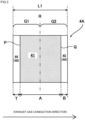
- Figure 3 is an enlarged longitudinal cross-sectional view of the first honeycomb body 4A illustrated in Figure 1 .
- Figure 4 is an expanded view of the flat foil 2 in the first honeycomb body 4A illustrated in Figure 1 .
- the direction of exhaust gas conduction illustrated in Figure 4 corresponds to the short-side direction of the flat foil 2
- the circumferential direction of the first honeycomb body illustrated in Figure 4 corresponds to the longitudinal direction of the flat foil 2.
- the flat foil 2 and the corrugated foil 3 of the first honeycomb body 4A are previously provided with a plurality of through holes 410 penetrating the foil in the thickness direction at corresponding positions in the direction of exhaust gas conduction (the short-side direction of the flat foil 2 and the corrugated foil 3).
- a region (opening region 41) in which the through holes 410 are provided in the axial direction is formed in the first honeycomb body 4A (cf. Figures 2 and 3 ).
- the through holes 410 are provided at positions separated from both edges of the flat foil 2 and the corrugated foil 3 in the short-side direction (cf. Figure 4 ).
- a non-opening region 46 without the through holes 410 is formed both in front of and behind the opening region 41 in the axial direction, and the non-opening region 46 includes a first non-opening region 44 extending from the inlet-side end of the opening region 41 to the inlet-side edge of the first honeycomb body 4A, and a second non-opening region 45 extending from the outlet-side end of the opening region 41 to the outlet-side edge of the first honeycomb body 4A.
- the inlet-side end of the opening region 41 refers to a boundary plane P orthogonal to the axial direction of the first honeycomb body 4A through the outer edge of the through holes 410 formed at the position closest to the inlet-side edge of the first honeycomb body 4A
- the outlet-side end of the opening region 41 refers to a boundary plane Q orthogonal to the axial direction of the first honeycomb body 4A through the outer edge of the through holes 410 formed at the position closest to the outlet-side edge of the first honeycomb body 4A.
- the region of the first honeycomb body 4A sandwiched between the boundary planes P and Q is the opening region 41
- the region of the first honeycomb body 4A closer to the inlet-side edge than the boundary plane P is the first non-opening region 44
- the region of the first honeycomb body 4A closer to the outlet-side edge than the boundary plane Q is the second non-opening region 45.
- the boundary planes P and Q of the first honeycomb body 4A in Figure 3 correspond to P' and Q', respectively, which are indicated by dash-dot lines in Figure 4 .
- the through holes 410 are arranged in a zigzag pattern along the axial direction.
- the "zigzag pattern” means that the arrangement relationship in which the next row of through holes is disposed on a virtual line extending in the axial direction through the intermediate position of the circumferentially adjacent through holes is continuous in the axial direction.
- the arrangement of the through holes 410 is not limited to the zigzag arrangement along the axial direction, and may be, for example, a matrix arrangement in which the through holes are arranged linearly along the axial direction and the circumferential direction of the first honeycomb body.
- the through holes 410 may be provided only on either the flat foil 2 or the corrugated foil 3.
- the position where the through holes 410 are provided in the flat foil 2 and the position where the through holes 410 are provided in the corrugated foil 3 may differ in the direction of exhaust gas conduction.
- the diameter (i.e., opening area) of the through hole 410, the shape of the through hole 410, and the like may be appropriately set according to the width, length, and the like of each of the flat foil 2 and the corrugated foil 3.
- the diameter of the through hole 410 is preferably set to 0.2 mm or more and 8 mm or less.
- the through holes 410 By setting the diameter of the through hole 410 to 8 mm or less, the through holes 410 becomes moderately small, and thus turbulence can be generated more easily in the exhaust gas, enabling more efficient purification of exhaust gas. Since the through holes 410 has a circular shape, a suitable opening area of each through hole 410 is 0.031 mm 2 or more and 50.3 mm 2 or less. As long as the opening area of each through hole 410 is 0.031 mm 2 or more and 50.3 mm 2 or less, the same effect can be obtained even if the shape of the through hole 410 is not circular (e.g., ellipses).
- the present inventors have carefully examined the mechanism by which cracks occur at the boundary between the opening region and the non-opening region in the metal carrier of Patent Literature 3. As a result, it was considered that the substantial difference in heat capacity and thermal conductivity between the opening region and the non-opening region leads to an increase in axial temperature gradient near the boundary between the opening region and the non-opening region, causing stress concentration and fracture. As a result of careful examination based on the above mechanism, the present inventors came up with a configuration divided into: a honeycomb body in the front part with the opening region; and a honeycomb body in the rear part without the opening region.
- the substrate for carrying catalyst 4 is formed solely of the first honeycomb body 4A, the axial temperature gradient near the boundary between the opening region and the non-opening region can be reduced, thereby suppressing the occurrence of cracks.
- the axial length of the substrate for carrying catalyst 4 cannot be sufficiently ensured compared to, for example, the metal carrier described in Patent Literature 3. This makes the absolute amount of the catalyst carried on the substrate for carrying catalyst 4 insufficient, causing a reduction in the steady-state purification performance (purification performance after the initial stage) of the honeycomb unit 1.
- the axial length of the substrate for carrying catalyst 4 is sufficiently ensured by excessively increasing the axial length of the first honeycomb body 4A, but with this configuration, as described above, pressure loss increases while purification performance is improved.
- the configuration of the present invention described above the configuration including the first honeycomb body 4A in the front part with the opening region and the second honeycomb body 4B in the rear part without the opening region
- (1) the axial length of the substrate for carrying catalyst 4 can be sufficiently ensured, thereby improving the steady-state purification performance of the honeycomb unit 1
- the axial length of the first honeycomb body 4A is not excessively long, so that the increase in the pressure loss can be suppressed.
- the present inventors have separately found that the presence or absence of through holes in the second honeycomb body 4B has little effect on the initial purification performance of the honeycomb unit 1.
- the lower limit of the axial length B of the second non-opening region 45 is not particularly limited, but can be, for example, about 1 mm.
- the ratio of the axial length A of the opening region 41 of the first honeycomb body 4A to the sum of the axial lengths of the honeycomb bodies constituting the substrate for carrying catalyst 4 (in the present embodiment, the sum of the axial length L1 of the first honeycomb body 4A and the axial length L2 of the second honeycomb body 4B) is X
- X is set to 20% or more and 80% or less.
- the axial length of the opening region 41 becomes excessively short, so that the initial purification performance of the honeycomb unit 1 cannot be sufficiently enhanced.
- X is increased, the axial length of the opening region 41 increases, thereby improving the purification performance, but the pressure loss also increases accordingly.
- the value of X can be set appropriately in the range of 20% or more and 80% or less based on the required output performance and exhaust gas level. Note that it is more preferable to set X to 25% or more and 55% or less.
- the axial length B of the second non-opening region 45 is preferably longer than the axial length T of the first non-opening region 44.
- the heat capacity of the exhaust gas inlet-side region G1 can be reduced compared to that of the exhaust gas outlet-side region G2 because the opening region 41 is unevenly distributed in the exhaust gas inlet-side region G1 of the first honeycomb body 4A.
- the "axial center” corresponds to the boundary plane R passing through the center in the axial direction of the first honeycomb body 4A and orthogonal to the axial direction of the first honeycomb body 4A.
- the first honeycomb body 4A and the second honeycomb body 4B are spaced apart from each other by a separation distance D (mm) in the axial direction of the substrate for carrying catalyst 4.
- the separation distance D (mm) can be set appropriately.
- the separation distance D (mm) is set to 2 ⁇ D ⁇ 20. The reason for this will be explained below.
- the flat foil 2 and the corrugated foil 3 may extend due to the heat of the exhaust gas.
- the first honeycomb body 4A and the second honeycomb body 4B are excessively close to each other, there is a risk that the first honeycomb body 4A and the second honeycomb body 4B may come into contact with each other and break.
- 2 mm or more is ensured for the separation distance D (mm).
- the second honeycomb body 4B when the exhaust gas discharged from the first honeycomb body 4A flows into the second honeycomb body 4B, the heat of the exhaust gas is dissipated to the outside of the honeycomb unit 1 via the outer mantle 5 at the separation section 6 between the first honeycomb body 4A and the second honeycomb body 4B. Therefore, the temperature of the exhaust gas when flowing into the second honeycomb body 4B decreases from the temperature of the exhaust gas when discharged from the first honeycomb body 4A. Since the second honeycomb body 4B is disposed downstream of the first honeycomb body 4A, its contribution to the steady-state purification performance is large.
- the separation distance D (mm) is preferably set to 2 ⁇ D ⁇ 10.
- the separation distance D (mm) is preferably set to 2 ⁇ D ⁇ 10.
- the separation distance D (mm) between the first honeycomb body 4A and the second honeycomb body 4B in the present invention can be set to less than 10 mm.
- the first honeycomb body 4A in the present invention is provided with the opening region 41 (a plurality of through holes 410), so that turbulence can be generated in the exhaust gas in the first honeycomb body 4A, and sufficient purification performance can be obtained even if the separation distance between the first honeycomb body 4A and the second honeycomb body 4B is reduced. Therefore, a new effect is that the substrate for carrying catalyst can be made smaller than the conventional substrate for carrying catalyst in which two honeycomb bodies without through holes formed in the foil are arranged in series.
- FIG. 5 is an enlarged view of the region S surrounded by the dashed line in Figure 4 .
- a triangle is drawn with the centers of gravity of three through holes 410 (in the present embodiment, centers C of the through holes 410) adjacent to each other as the vertex.
- the area of the triangle is defined as a total area, and the area of portions where the triangle overlaps the through holes is defined as an overlap area.
- the opening ratio is calculated as "the ratio of the overlap area to the total area.” Even if the through hole has a shape other than circular, the opening ratio can be similarly defined using the center of gravity of the through hole. Even if the through holes are not arranged in a zigzag pattern along the axial direction illustrated in Figure 4 (e.g., the matrix arrangement described above), the opening ratio can be calculated in accordance with the above definition.
- the opening ratio is set to 20% or more and 60% or less.
- the opening ratio is set to 20% or more, the heat capacity of the first honeycomb body 4A can be reduced to a reasonable level, thus improving the initial purification performance more sufficiently.
- the opening ratio is set to 60% or less, the durability of the first honeycomb body 4A can be further improved because the foil in the opening region 41 can be retained more sufficiently.
- Tables 1 to 4 show parameter conditions for each of the examples and comparative examples.
- Table 1 Honeycomb body diameter First honeycomb body length L1 First non-opening region length T Opening region length A Second non-opening region length B Second honeycomb body length L2 Separation distance D
- Example 1 50mm 60mm 8mm 44.0mm 8.0mm 60mm 20mm
- Example 2 50mm 60mm 6mm 44.0mm 10.0mm 60mm 20mm
- Example 3 50mm 60mm 2mm 51.9mm 6.1mm 60mm 20mm
- Example 4 50mm 60mm 10mm 44.0mm 6.0mm 60mm 20mm
- Comparative Example 1 50mm 120mm 6mm 44.0mm 70.0mm - - Comparative Example 2 50mm 60mm 2mm 44.0mm 14.0mm 60mm 20mm Comparative Example 3 50mm 60mm 1mm 51.9mm 7.1mm 60mm 20mm Comparative Example 4 50mm 60mm 15mm 44.0mm 1.0mm 60
- catalytic converters using the honeycomb units 1 according to the present invention were prepared as follows. Two Fe-20Cr-5Al stainless steel foils with a width of 60 mm and a foil thickness of 50 ⁇ m were drilled with a diameter of 1 mm. The holes were arranged in a zigzag arrangement and the opening ratio was set to 40%. The drilling was performed so that the axial length T of the first non-opening region 44, the axial length A of the opening region 41, and the axial length B of the second non-opening region 45 were the values listed in Examples 1 to 4 shown in Table 1.
- One of the two drilled foils was used as the flat foil 2 and the other as the corrugated foil 3.
- the foil used as the corrugated foil 3 was corrugated so that the cell density was 300 cells per inch.
- brazing foil with a width of 20 mm and a thickness of 25 ⁇ m was wrapped around the obtained first honeycomb body 4A and second honeycomb body 4B at predetermined positions, which were inserted into the outer mantle 5 with a length of 140 mm and a thickness of 1.5 mm so that the separation distance D between the first honeycomb body 4A and the second honeycomb body 4B in the axial direction was 20 mm.
- BNi-5 was used as the brazing foil
- SUS436L was used as the outer mantle.
- diameter reduction was applied so that the outer diameter of the outer mantle 5 was 53 mm.
- a powder brazing material was applied to the first honeycomb body 4A and the second honeycomb body 4B at predetermined positions. BNi-5 was used as the powder brazing material.
- first honeycomb body 4A and the second honeycomb body 4B two to three layers of corrugated foil 2 and flat foil 3 are joined from the outermost periphery in a region 10 mm from the gas inlet-side end edge, the first honeycomb body 4A and the outer mantle 5 are joined in the region 10 mm from the outlet-side edge of the first honeycomb body 4A, and the second honeycomb body 4B and the outer mantle 5 are joined in the region 10 mm from the outlet-side edge of the second honeycomb body 4B.
- the honeycomb unit 1 was obtained by vacuum heat treatment at 1200°C for 10 minutes in a vacuum atmosphere, followed by cooling.
- a wash coat slurry containing 1.25 g of palladium per 100 g of ceria-zirconia-lanthana-alumina as the main component was passed through the first honeycomb body 4A and the second honeycomb body 4B in the honeycomb unit 1. After the excess wash coat slurry was removed, the washcoat was dried at 180°C for 1 hour and then baked at 500°C for 2 hours, whereby a wash coat slurry layer was carried on a metal foil at an amount of 200 g/L by weight after drying per volume of the first honeycomb body 4A and the second honeycomb body 4B to obtain a catalytic converter. The amount of palladium carried was 2.5 g/L.
- a catalytic converter was prepared as follows. Two Fe-20Cr-5Al stainless steel foils with a width of 120 mm and a foil thickness of 50 ⁇ m were drilled with a diameter of 1.0 mm. The holes were arranged in a zigzag arrangement and the opening ratio was set to 40%. The drilling was performed so that the axial length T of the first non-opening region 44 was 6 mm, the axial length A of the opening region 41 was 44.0 mm, and the axial length B of the second non-opening region 45 was 70.0 mm.
- the foil used as the corrugated foil 3 was corrugated so that the cell density was 300 cells per inch.
- a honeycomb body with a diameter of 50 mm, a length of 120 mm, and a cell density of 300 cells per inch was obtained by winding the flat foil 2 and the corrugated foil 3 in the overlapped state.
- brazing foil with a width of 20 mm and a thickness of 25 ⁇ m was wound around the obtained honeycomb body at a predetermined position, and the honeycomb body was inserted into the outer mantle 5 with a length of 120 mm and a thickness of 1.5 mm.
- BNi-5 was used as the brazing foil
- SUS436L was used as the outer mantle.
- diameter reduction was applied so that the outer diameter of the outer mantle 5 was 53 mm.
- the powder brazing material was applied to the obtained honeycomb body at the predetermined position.
- BNi-5 was used as the powder brazing material.
- the joint structure of the honeycomb body and the joint structure of the honeycomb body and the outer mantle 5 were the same as those of Example 1.
- honeycomb unit was obtained by vacuum heat treatment as in Example 1, and the catalytic converter was obtained by catalyst-carrying treatment as in Example 1.
- a catalytic converter was obtained by performing drilling as in Example 1 so that the axial length T of the first non-opening region 44 was 2 mm, the axial length A of the opening region 41 was 44.0 mm, and the axial length B of the second non-opening region 45 was 14.0 mm, and other manufacturing conditions were the same as those in Example 1.
- Example 3 a catalytic converter was obtained by performing drilling as in Example 1 so that the axial length T of the first non-opening region 44 was 1 mm, the axial length A of the opening region 41 was 51.9 mm, and the axial length B of the second non-opening region 45 was 7.1 mm, and other manufacturing conditions were the same as those in Example 1.
- Example 4 a catalytic converter was obtained by performing drilling as in Example 1 so that the axial length T of the first non-opening region 44 was 15 mm, the axial length A of the opening region 41 was 44.0 mm, and the axial length B of the second non-opening region 45 is 1.0 mm, and other manufacturing conditions were the same as those in Example 1.
- the structural durability of the catalytic converter obtained in each of Examples 1 to 4 and Comparative Examples 1 to 4 was evaluated by conducting heating and cooling cycle tests on an engine bench. A test device and the substrate for carrying catalyst were connected via a cone. Welding was used as the connection method. A single-cylinder gasoline engine with a displacement of 400cc was used for the engine.
- a temperature pattern in which the inlet-side temperature of the gas flowing into the substrate for carrying catalyst was changed between 1000°C and 100°C or less was selected as a pattern for a cooling/heating cycle. That is, a cooling/heating cycle including the following steps was set as one cycle: a warming step in which the inlet-side temperature of the gas reaches 900°C in about 30 seconds by rotating the engine for 5 minutes from the engine stop state; a holding step in which the temperature after the reach (1000°C) is held; and a cooling step in which the engine is stopped and room temperature air is supplied for 5 minutes to cool the gas to 100°C in about 60 seconds and then room temperature air is allowed to flow continuously.
- the honeycomb body After repetition of this cooling/heating cycle for 1000 cycles, the honeycomb body was observed to check for the occurrence of cracks in the boundary region between the opening region 41 and the non-opening region 45.
- the honeycomb body in each of Comparative Examples 1 and 2 had cracks near the boundary between the opening region 41 and the second non-opening region 45. The cracks propagated in the radial direction and penetrated to the center of the honeycomb body.
- the first honeycomb body 4A in Comparative Example 3 no cracks occurred near the boundary between the opening region 41 and the second non-opening region 45, but a failure occurred in which the foil at the inlet-side edge was defective due to foil chipping.
- the honeycomb body in Comparative Example 4 had cracks near the boundary between the opening region 41 and the first non-opening region 44.
- the cracks propagated in the radial direction and penetrated to the center of the honeycomb body.
- no cracks propagating in the radial direction were observed in the honeycomb body in each of Examples 1 to 4.
- X the ratio of the axial length A of the opening region 41 of the first honeycomb body 4A to the sum of the axial length L1 of the first honeycomb body 4A and the axial length L2 of the second honeycomb body 4B.
- a catalytic converter was prepared as follows. Two Fe-20Cr-5Al stainless steel foils with a foil thickness of 50 ⁇ m were drilled with a diameter of 1 mm. The holes were arranged in a zigzag arrangement and the opening ratio was set to 40%. The drilling was performed so that the axial length T of the first non-opening region 41, the axial length A of the opening region 41, and the axial length B of the second non-opening region 45 were the values in each of the examples and comparative examples shown in Table 1. The width of the two Fe-20Cr-5A1 stainless steel foils was set appropriately to be the length L1 of the first honeycomb body 4A in each of the examples and comparative examples (cf. Table 1).
- the foil used as the corrugated foil 3 was corrugated so that the cell density was 300 cells per inch.
- the first honeycomb body 4A with a diameter of 50 mm and a cell density of 300 cells per inch was obtained by winding the flat foil 2 and the corrugated foil 3 in the overlapped state.
- the second honeycomb body 4B with a diameter of 50 mm and a cell density of 300 cells per inch was obtained by winding a pair of undrilled flat foil and corrugated foil, made of Fe-20Cr-5Al stainless steel foil with a foil thickness of 50 ⁇ m, in the overlapped state.
- the corrugated foil was corrugated using the same method as described above.
- the width of each of the two Fe-20Cr-5Al stainless foils was appropriately set to the length L2 of the second honeycomb body 4B in each of the examples and comparative examples (cf. Table 1).
- honeycomb unit was obtained by vacuum heat treatment as in Example 1, and the catalytic converter was obtained by catalyst-carrying treatment as in Example 1.
- a catalytic converter for comparison of pressure loss and purification performance (hereinafter referred to as a reference catalytic converter)
- a catalytic converter only including the second honeycomb body 4B with a length of 100 mm was manufactured.
- the manufacturing conditions of the reference catalytic converter are the same as those of Examples 5 to 11 and Comparative Examples 5 to 6 except that the first honeycomb body 4A is not included.
- the pressure loss was evaluated by allowing air at normal temperature, adjusted to a predetermined flow rate, to flow through the catalytic converter, obtained in each of the examples and comparative examples, and measuring the pressure difference before and after the catalytic converter.
- the pressure loss was evaluated by allowing air at 20°C to flow at a flow rate of 2.5 Nm 3 /min. This is about 21 m/s on average in terms of flow velocity.
- the pressure loss of each of the examples and comparative examples was evaluated as the rate of increase (hereinafter referred to as a pressure loss increase rate) relative to the pressure loss in the reference catalytic converter.
- a model gas (a gas mixture consisting of carbon monoxide, propylene, nitric oxide, oxygen, carbon dioxide, steam, and nitrogen), adjusted to a predetermined flow rate (in the present embodiment, 300 liters per minute in the standard state) and heated to 300°C, was allowed to flow through the catalytic converter at normal temperature obtained in each of the examples and comparative examples, and the time required for the propylene concentration to decrease by 50% (hereinafter referred to as 50% purification time) was evaluated as the purification performance during the cold start.
- a model gas a gas mixture consisting of carbon monoxide, propylene, nitric oxide, oxygen, carbon dioxide, steam, and nitrogen
- the concentrations of the respective gases constituting the model gas were as follows: carbon monoxide, 5000 ppm; propylene, 500 ppm; nitric oxide, 500 ppm; oxygen, 4500 ppm; carbon dioxide, 14%; water vapor, 10%; with nitrogen making up the remainder.
- the purification performance (50% purification time) of each of the examples and comparative examples was evaluated as the rate of increase (hereinafter referred to as a purification performance increase rate) relative to the inverse of 50% purification time in the reference catalytic converter, taking the inverse of 50% purification time.
- the separation distance D between the first honeycomb body 4A and the second honeycomb body 4B and the purification performance was investigated. Specifically, in Examples 12 to 15 and Comparative Examples 7 to 9, the separation distance D was changed in various ways (cf. Table 1), and the purification performance in each of the examples and comparative examples was compared. The manufacturing was performed in the same manner as in Example 1 so that the other manufacturing conditions were the values for each of the examples and comparative examples as shown in Table 1, to obtain a catalytic converter.
- a model gas (a gas mixture consisting of carbon monoxide, propylene, nitric oxide, oxygen, carbon dioxide, steam, and nitrogen) heated to 300°C was allowed to flow through the catalytic converter at normal temperature at a predetermined flow rate, and the time required for the concentration of propylene to decrease by 90% was evaluated as the purification performance in the steady state.
- concentrations of the respective gases constituting the model gas were as follows: carbon monoxide, 5000 ppm; propylene, 500 ppm; nitric oxide, 500 ppm; oxygen, 4500 ppm; carbon dioxide, 14%; water vapor, 10%; with nitrogen making up the remainder.
- the purification performance was evaluated by allowing the flow of 300 liters per minute under the standard condition.
- the separation distance D was set to 1 mm
- the first honeycomb body 4A and the second honeycomb body 4B were damaged, and hence the 90% purification time could not be measured. This is because foil elongation occurred in the foil constituting the first honeycomb body 4A, and the outlet-side edge of the first honeycomb body 4A and the inlet-side edge of the second honeycomb body 4B came into contact.
- Example 16 as shown in Table 1, the catalytic converter was obtained by performing drilling so that the axial length T of the first non-opening region 44 was 2 mm, the axial length A of the opening region 41 was 44.0 mm, and the axial length B of the second non-opening region 45 was 9.0 mm, and other manufacturing conditions were the same as those in Example 5.
- Example 17 as shown in Table 1, the catalytic converter was obtained by performing drilling so that the axial length T of the first non-opening region 44 was 10 mm, the axial length A of the opening region 41 was 44.0 mm, and the axial length B of the second non-opening region 45 was 1.0 mm, and other manufacturing conditions were the same as those in Example 5.
- Example 16 While the pressure loss increase rate did not change between Example 16 and Example 17, the purification performance was improved in Example 16 relative to Example 17. As a result, the ratio of the pressure loss increase rate to the purification performance increase rate was evaluated as "Excellent” in Example 16 and "Good” in Example 17. That is, when the length of the axial length T of the first non-opening region 44 was shorter than the length of the axial length B of the second non-opening region 45, the relationship between the pressure loss and the purification performance was better.
- Examples 18 to 25 and Comparative Examples 10 to 18 the effect of changing the hole diameter from Examples 1 to 4 and Comparative Examples 1 to 4 was investigated.
- the hole diameter was set to 2 mm.
- the hole diameter was set to 4 mm.
- the hole diameter was set to 8 mm.
- Other parameters were set as shown in Tables 1 to 4.
- the catalytic converter was manufactured using the same manufacturing method as in Example 1 and tested in the same manner as in Example 1 to investigate the structural durability of the catalytic converter.
- the first honeycomb body 4A in each of Comparative Examples 10, 13, and 16 had cracks near the boundary between the opening region 41 and the second non-opening region 45. The cracks propagated in the radial direction and penetrated to the center of the honeycomb body. In the first honeycomb body 4A in each of Comparative Examples 11, 14, and 17, no cracks occurred near the boundary between the opening region 41 and the second non-opening region 45, but a failure occurred in which the foil at the inlet-side edge was defective due to foil chipping.
- the first honeycomb body 4A in each of Comparative Examples 12, 15, and 18 had cracks near the boundary between the opening region 41 and the first non-opening region 44. The cracks propagated in the radial direction and penetrated to the center of the honeycomb body.
- Example 26 to 31 and Comparative Examples 19 to 24 the effect of changing the opening ratio from Examples 1 to 4 and Comparative Examples 1 to 4 was investigated.
- the opening ratio was set to 20%.
- the opening ratio was set to 60%.
- Other parameters were set as shown in Tables 3 and 4.
- the catalytic converter was manufactured using the same manufacturing method as in Example 1 and tested in the same manner as in Example 1 to investigate the structural durability of the catalytic converter.
- the first honeycomb body 4A in each of Comparative Examples 19 and 22 had cracks near the boundary between the opening region 41 and the second non-opening region 45. The cracks propagated in the radial direction and penetrated to the center of the honeycomb body.
- the first honeycomb body 4A in Comparative Examples 20 and 23 no cracks occurred near the boundary between the opening region 41 and the second non-opening region 45, but a failure occurred in which the foil at the inlet-side edge was defective due to foil chipping.
- the first honeycomb body 4A in each of Comparative Examples 21 and 24 had cracks near the boundary between the opening region 41 and the first non-opening region 44. The cracks propagated in the radial direction and penetrated to the center of the honeycomb body.
- Examples 32 to 34 and Comparative Examples 25 to 27 the effects of changing the foil thickness and cell density from Examples 1 to 4 and Comparative Examples 1 to 4 were investigated.
- the foil thickness was 30 ⁇ m and the cell density was 400cpsi.
- Other parameters were set as shown in Tables 3 and 4.
- the catalytic converter was manufactured using the same manufacturing method as in Example 1 and tested in the same manner as in Example 1 to investigate the structural durability of the catalytic converter.
- the first honeycomb body 4A in Comparative Example 25 had cracks near the boundary between the opening region 41 and the second non-opening region 45. The cracks propagated in the radial direction and penetrated to the center of the honeycomb body. In the first honeycomb body 4A in Comparative Example 26, no cracks occurred near the boundary between the opening region 41 and the second non-opening region 45, but a failure occurred in which the foil at the inlet-side edge was defective due to foil chipping. The first honeycomb body 4A in Comparative Example 27 had cracks near the boundary between the opening region 41 and the first non-opening region 44. The cracks propagated in the radial direction and penetrated to the center of the honeycomb body.
- Example 35 to 37 and Comparative Examples 28 to 30 the effects of changing the diameter and length of the honeycomb body from Examples 1 to 4 and Comparative Examples 1 to 4 were investigated.
- the diameter and the axial length of each of the first honeycomb body 4A and the second honeycomb body 4B were 80 mm and 40 mm, respectively.
- Other parameters were set as shown in Tables 3 and 4.
- the catalytic converter was manufactured using the same manufacturing method as in Example 1 and tested in the same manner as in Example 1 to investigate the structural durability of the catalytic converter.
- the first honeycomb body 4A in Comparative Example 28 had cracks near the boundary between the opening region 41 and the second non-opening region 45. The cracks propagated in the radial direction and penetrated to the center of the honeycomb body. In the first honeycomb body 4A in Comparative Example 29, no cracks occurred near the boundary between the opening region 41 and the second non-opening region 45, but a failure occurred in which the foil at the inlet-side edge was defective due to foil chipping.
- the first honeycomb body 4A in Comparative Example 30 had cracks near the boundary between the opening region 41 and the first non-opening region 44. The cracks propagated in the radial direction and penetrated to the center of the honeycomb body.
Landscapes
- Chemical & Material Sciences (AREA)
- Engineering & Computer Science (AREA)
- Chemical Kinetics & Catalysis (AREA)
- Health & Medical Sciences (AREA)
- Combustion & Propulsion (AREA)
- Mechanical Engineering (AREA)
- Toxicology (AREA)
- Organic Chemistry (AREA)
- Materials Engineering (AREA)
- General Engineering & Computer Science (AREA)
- Biomedical Technology (AREA)
- Environmental & Geological Engineering (AREA)
- Analytical Chemistry (AREA)
- General Chemical & Material Sciences (AREA)
- Oil, Petroleum & Natural Gas (AREA)
- Catalysts (AREA)
- Exhaust Gas Treatment By Means Of Catalyst (AREA)
- Exhaust Gas After Treatment (AREA)
Abstract
Description
- The present invention relates to a catalyst-carrying substrate used for purifying air pollutants contained in exhaust gas.
- A catalytic converter, constructed by fitting a metallic honeycomb body (substrate for carrying catalyst) into an outer mantle made of a heat-resistant alloy, is known as a purification device for purifying exhaust gas discharged from an internal combustion engine. By placing the catalytic converter in the exhaust gas path, the exhaust gas passing through the catalytic converter comes into contact with the catalyst over a wide area, enabling efficient purification of the exhaust gas. As the honeycomb body, the following is used: a honeycomb body constructed by alternately laminating a metallic flat foil and a corrugated foil formed by corrugating the flat foil, a honeycomb body formed by winding a metallic flat foil and a corrugated foil, or other types of honeycomb bodies.
- To improve the purification performance of exhaust gas in a catalytic converter, a honeycomb body provided with holes across the entire foil has been proposed (cf.
Patent Literatures 1 and 2). By forming holes in the foil, (A) the heat capacity of the honeycomb body is reduced, so that the heat of the exhaust gas can be used for early activation of the catalyst carried on the honeycomb body, and (B) the exhaust gas passing through the honeycomb body is likely to be turbulent, enabling more efficient purification of the exhaust gas. Therefore, the purification performance of the honeycomb body can be improved. - However, in the honeycomb body disclosed in each of
Patent Literatures - In view of this point,
Patent Literature 3 proposes a metal carrier (honeycomb body) provided with an opening only upstream of an exhaust gas path in a flat foil and/or a corrugated foil provided in the honeycomb body. In the metal carrier, a portion on the exhaust gas inlet-side where the heated exhaust gas comes into contact with the catalyst at an early stage contributes greatly to the early activation of the catalyst. Therefore, by providing an opening upstream of the exhaust gas path, the effect of early activation of the catalyst described in (A) above can be fully enjoyed. Further, as described in (B) above, by forming an opening in the foil, turbulence can be likely to be generated in the exhaust gas. Therefore, according to the structure disclosed inPatent Literature 3, purification performance can be improved. Moreover, by not providing an opening downstream of the exhaust gas path, an increase in pressure loss, an issue inPatent Literatures -
- Patent Literature 1:
Japanese Patent Laid-Open No. 55-132640 - Patent Literature 2:
Japanese Patent Laid-Open No. 62-53744 - Patent Literature 3:
Japanese Patent Laid-Open No. 6-320014 - Patent Literature 4: International Publication No.
WO 90/03842 A1 - Patent Literature 5:
Japanese Patent Laid-Open No. 2011-156505 - Patent Literature 6:
Japanese Utility Model Laid-Open No. 2-83320 - Patent Literature 7:
Japanese Patent Laid-Open No. 5-195763 - However, as a result of durability tests of the metal carrier proposed in
Patent Literature 3 through exhaust gas conduction, a phenomenon was confirmed where cracks occur at a boundary between a region provided with the opening (hereinafter referred to as an opening region) and a region without the opening (hereinafter referred to as a non-opening region), leading to the breakage of the metal carrier. - Therefore, it is an object of the present invention to provide a substrate for carrying catalyst that: (1) enhances purification performance; (2) suppresses an increase in pressure loss; and (3) suppresses breakage at a boundary between an opening region and a non-opening region.
- To solve the above problem, the present invention is as follows.
- (1) A substrate for carrying catalyst including a plurality of honeycomb bodies, the substrate for carrying catalyst being used for purifying exhaust gas of a vehicle. The plurality of honeycomb bodies are arranged side by side such that central axes of each of the honeycomb bodies substantially coincide. Of the plurality of honeycomb bodies, many through holes are formed in one or more metal foils of a first honeycomb body positioned closest to an exhaust gas inlet side, and no through hole is formed in metal foils of other remaining honeycomb bodies. When the first honeycomb body is divided in the axial direction into the following regions: an opening region in which the through holes are formed; a first non-opening region from the exhaust gas inlet-side end of the opening region to the exhaust gas inlet-side edge of the first honeycomb body; and a second non-opening region from the exhaust gas outlet-side end of the opening region to the exhaust gas outlet-side edge of the first honeycomb body, a length of the first non-opening region in the axial direction is 2 mm or more and 10 mm or less, and a length of the second non-opening region in the axial direction is 10 mm or less. When a honeycomb body adjacent to the first honeycomb body in the axial direction is defined as a second honeycomb body, the first honeycomb body and the second honeycomb body are separated in the axial direction, and a separation distance between the first honeycomb body and the second honeycomb body in the axial direction is 2 mm or more and 20 mm or less. A ratio of a length of the opening region in the axial direction to a sum of lengths of the plurality of honeycomb bodies in the axial direction is 20% or more and 80% or less.
- (2) The substrate for carrying catalyst according to (1), in which the separation distance between the first honeycomb body and the second honeycomb body in the axial direction is 2 mm or more and less than 10 mm.
- (3) The substrate for carrying catalyst according to (1) or (2), in which the length of the second non-opening region in the axial direction is longer than the length of the first non-opening region in the axial direction.
- (4) A honeycomb unit including: the substrate for carrying catalyst according to any one of (1) to (3); and an outer mantle that houses the substrate for carrying catalyst.
- (5) A catalytic converter including: the honeycomb unit according to (4); and a catalyst carried on each of the plurality of honeycomb bodies.
- The substrate for carrying catalyst according to the present invention can: (1) enhance purification performance; (2) suppress an increase in pressure loss; and (3) suppress breakage at a boundary between an opening region and a non-opening region.
-
- [
Figure 1] Figure 1 is a perspective view of a honeycomb unit in the present embodiment. - [
Figure 2] Figure 2 is a longitudinal cross-sectional view of the honeycomb unit illustrated inFigure 1 . - [
Figure 3] Figure 3 is an enlarged longitudinal cross-sectional view of afirst honeycomb body 4A illustrated inFigure 1 . - [
Figure 4] Figure 4 is an expanded view of aflat foil 2 in thefirst honeycomb body 4A illustrated inFigure 1 . - [
Figure 5] Figure 5 is an enlarged view of a region S surrounded by a dashed line inFigure 4 . - An embodiment according to the present invention will be described below with reference to the drawings.
Figure 1 is a perspective view of a honeycomb unit in the present embodiment.Figure 2 is a longitudinal cross-sectional view of the honeycomb unit illustrated inFigure 1 . The arrow illustrated inFigure 2 indicates the direction of exhaust gas conduction, and this direction coincides with the axial direction of a substrate for carrying catalyst. Referring toFigures 1 and 2 , ahoneycomb unit 1 includes a substrate for carryingcatalyst 4 and anouter mantle 5 made of heat-resistant metal for housing the substrate for carryingcatalyst 4. In the present embodiment, the substrate for carryingcatalyst 4 has a configuration with serial arrangement of afirst honeycomb body 4A disposed upstream of the exhaust gas path and asecond honeycomb body 4B that is disposed downstream of the exhaust gas path, with its central axis substantially coincident with that of thefirst honeycomb body 4A, and is adjacent to thefirst honeycomb body 4A in the axial direction. However, one or more honeycomb bodies having the same configuration as thesecond honeycomb body 4B may be further arranged in series downstream of thesecond honeycomb body 4B. The phrase "its central axis substantially coincident" does not only mean the complete overlap of the center axes but also means allowing slight deviations therebetween due to manufacturing errors or the like in the honeycomb bodies. The cell density of each of thefirst honeycomb body 4A and thesecond honeycomb body 4B is preferably set to 100 cells to 600 cells per square inch. By increasing the cell density, purification performance is improved, but the pressure loss also increases accordingly. Therefore, the value of the cell density to be set may be appropriately selected according to the required output performance and exhaust gas level. - The
first honeycomb body 4A and thesecond honeycomb body 4B are each constructed by winding aflat foil 2 and acorrugated foil 3, which are made of a heat-resistant alloy, around the axis in an overlapped state, and joining theflat foil 2 and thecorrugated foil 3 to each other using a brazing material. Thus, theflat foil 2 and thecorrugated foil 3 are alternately laminated in the radial direction. According to the configuration described above, many gas flow paths extending in the axial direction can be formed inside thefirst honeycomb body 4A and thesecond honeycomb body 4B. Note that thecorrugated foil 3 is formed by corrugating theflat foil 2. Thehoneycomb unit 1 is constructed by inserting thefirst honeycomb body 4A and thesecond honeycomb body 4B into theouter mantle 5 and joining the outermost peripheral surfaces of thefirst honeycomb body 4A and thesecond honeycomb body 4B and the inner peripheral surface of theouter mantle 5 with the brazing material. The joint positions of theflat foil 2 and thecorrugated foil 3 and the joint positions of the first andsecond honeycomb bodies outer mantle 5 are not particularly limited, but the joining can be performed at known joint positions such as those shown inPatent Literatures flat foil 2 and thecorrugated foil 3 and for joining the first andsecond honeycomb bodies outer mantle 5, brazing foil can be used, for example, a nickel-based brazing material such as BNi-2 and BNi-5 can be used. However, a powdery or granular brazing material different from the brazing foil can also be used. - As the heat-resistant alloy used for the
flat foil 2 and thecorrugated foil 3, Fe-20Cr-5Al stainless steel can be suitably employed, but the present invention is not limited thereto, and various heat-resistant stainless steels containing Al in the alloy composition can be employed. Generally, an alloy containing 15 to 25 mass% Cr and 2 to 8 mass% Al can be used as the heat-resistant alloy. For example, an Fe-20Cr-5Al alloy, an Fe-18Cr-3Al alloy, an Fe-20Cr-8Al alloy, and the like can be used. By reducing the foil thickness of theflat foil 2 and thecorrugated foil 3, the heat capacity of the honeycomb body is reduced, enabling early activation of the catalyst and a further improvement in initial purification performance. On the other hand, when the foil thicknesses of theflat foil 2 and thecorrugated foil 3 are reduced, the strength of the foil is reduced, thus leading to a decrease in the durability of the honeycomb body. Therefore, the foil thicknesses of theflat foil 2 and thecorrugated foil 3 can be set appropriately based on the required durability and purification performance. Preferably, the foil thicknesses of theflat foil 2 and thecorrugated foil 3 are set to 20 µm to 100 µm. For example, stainless steel such as SUS436L can be employed as the heat-resistant alloy used for theouter mantle 5, but the present invention is not limited thereto, and various heat-resistant alloys can be used. Note that the thickness of theouter mantle 5 is preferably set to 1 mm to 2 mm. - A catalyst (not illustrated) is carried on the
flat foil 2 and thecorrugated foil 3. The catalyst can be carried on theflat foil 2 and thecorrugated foil 3 by applying a predetermined wash coat slurry to the foil surfaces of thefirst honeycomb body 4A and thesecond honeycomb body 4B, followed by drying and baking. As the wash coat slurry, it is possible to use, for example, a slurry formed by stirring γ-alumina powder, lanthanum oxide, zirconium oxide, and cerium oxide in an aqueous solution of palladium nitrate. - The honeycomb unit carrying a catalyst (i.e., a catalytic converter) can be placed in the exhaust gas path of a vehicle so that exhaust gas flowing in from the inlet-
side end 1A is discharged to the outlet-side end 1B. The vehicle includes two-wheelers, four-wheelers, off-road vehicles, and the like. When the exhaust gas flowing into the gas flow path of the honeycomb body comes into contact with the catalyst, carbon monoxide (CO), hydrocarbons, and nitrogen oxides (NOx) contained in the exhaust gas are rendered harmless, enabling clean gas to be discharged outside the vehicle. -
Figure 3 is an enlarged longitudinal cross-sectional view of thefirst honeycomb body 4A illustrated inFigure 1 .Figure 4 is an expanded view of theflat foil 2 in thefirst honeycomb body 4A illustrated inFigure 1 . The direction of exhaust gas conduction illustrated inFigure 4 corresponds to the short-side direction of theflat foil 2, and the circumferential direction of the first honeycomb body illustrated inFigure 4 corresponds to the longitudinal direction of theflat foil 2. Referring toFigure 4 , theflat foil 2 and thecorrugated foil 3 of thefirst honeycomb body 4A are previously provided with a plurality of throughholes 410 penetrating the foil in the thickness direction at corresponding positions in the direction of exhaust gas conduction (the short-side direction of theflat foil 2 and the corrugated foil 3). By winding theflat foil 2 and thecorrugated foil 3 around the axis in the overlapped state, a region (opening region 41) in which the throughholes 410 are provided in the axial direction is formed in thefirst honeycomb body 4A (cf.Figures 2 and3 ). Here, in the present embodiment, the throughholes 410 are provided at positions separated from both edges of theflat foil 2 and thecorrugated foil 3 in the short-side direction (cf.Figure 4 ). That is, in thefirst honeycomb body 4A, anon-opening region 46 without the throughholes 410 is formed both in front of and behind theopening region 41 in the axial direction, and thenon-opening region 46 includes a firstnon-opening region 44 extending from the inlet-side end of theopening region 41 to the inlet-side edge of thefirst honeycomb body 4A, and a secondnon-opening region 45 extending from the outlet-side end of theopening region 41 to the outlet-side edge of thefirst honeycomb body 4A. In the present embodiment, "the inlet-side end of theopening region 41" refers to a boundary plane P orthogonal to the axial direction of thefirst honeycomb body 4A through the outer edge of the throughholes 410 formed at the position closest to the inlet-side edge of thefirst honeycomb body 4A, and "the outlet-side end of theopening region 41" refers to a boundary plane Q orthogonal to the axial direction of thefirst honeycomb body 4A through the outer edge of the throughholes 410 formed at the position closest to the outlet-side edge of thefirst honeycomb body 4A. That is, the region of thefirst honeycomb body 4A sandwiched between the boundary planes P and Q is theopening region 41, the region of thefirst honeycomb body 4A closer to the inlet-side edge than the boundary plane P is the firstnon-opening region 44, and the region of thefirst honeycomb body 4A closer to the outlet-side edge than the boundary plane Q is the secondnon-opening region 45. The boundary planes P and Q of thefirst honeycomb body 4A inFigure 3 correspond to P' and Q', respectively, which are indicated by dash-dot lines inFigure 4 . By providing the firstnon-opening region 44 at the inlet-side edge of thefirst honeycomb body 4A, it is possible to further suppress the damage of the foil of thefirst honeycomb body 4A due to exhaust gas pulsation. - Referring to
Figure 4 , in the present embodiment, the throughholes 410 are arranged in a zigzag pattern along the axial direction. Here, the "zigzag pattern" means that the arrangement relationship in which the next row of through holes is disposed on a virtual line extending in the axial direction through the intermediate position of the circumferentially adjacent through holes is continuous in the axial direction. However, the arrangement of the throughholes 410 is not limited to the zigzag arrangement along the axial direction, and may be, for example, a matrix arrangement in which the through holes are arranged linearly along the axial direction and the circumferential direction of the first honeycomb body. Further, the throughholes 410 may be provided only on either theflat foil 2 or thecorrugated foil 3. Moreover, the position where the throughholes 410 are provided in theflat foil 2 and the position where the throughholes 410 are provided in thecorrugated foil 3 may differ in the direction of exhaust gas conduction. - The diameter (i.e., opening area) of the through
hole 410, the shape of the throughhole 410, and the like may be appropriately set according to the width, length, and the like of each of theflat foil 2 and thecorrugated foil 3. The diameter of the throughhole 410 is preferably set to 0.2 mm or more and 8 mm or less. By setting the diameter of the throughhole 410 to 0.2 mm or more, the possibility of the throughholes 410 being blocked by the catalyst can be reduced, and thus turbulence can be generated more easily in the exhaust gas, enabling more efficient purification of exhaust gas. By setting the diameter of the throughhole 410 to 8 mm or less, the throughholes 410 becomes moderately small, and thus turbulence can be generated more easily in the exhaust gas, enabling more efficient purification of exhaust gas. Since the throughholes 410 has a circular shape, a suitable opening area of each throughhole 410 is 0.031 mm2 or more and 50.3 mm2 or less. As long as the opening area of each throughhole 410 is 0.031 mm2 or more and 50.3 mm2 or less, the same effect can be obtained even if the shape of the throughhole 410 is not circular (e.g., ellipses). - First, the present inventors have carefully examined the mechanism by which cracks occur at the boundary between the opening region and the non-opening region in the metal carrier of
Patent Literature 3. As a result, it was considered that the substantial difference in heat capacity and thermal conductivity between the opening region and the non-opening region leads to an increase in axial temperature gradient near the boundary between the opening region and the non-opening region, causing stress concentration and fracture. As a result of careful examination based on the above mechanism, the present inventors came up with a configuration divided into: a honeycomb body in the front part with the opening region; and a honeycomb body in the rear part without the opening region. According to this configuration, it is possible to enjoy the same effects of "improvement in purification performance" and "suppression of an increase in pressure loss" as those of the metal carrier disclosed inPatent Literature 3, and to reduce the axial temperature gradient near the boundary between the opening region and the non-opening region, thereby suppressing the occurrence of cracks at the boundary. - Here, even if the substrate for carrying
catalyst 4 is formed solely of thefirst honeycomb body 4A, the axial temperature gradient near the boundary between the opening region and the non-opening region can be reduced, thereby suppressing the occurrence of cracks. However, with this configuration, the axial length of the substrate for carryingcatalyst 4 cannot be sufficiently ensured compared to, for example, the metal carrier described inPatent Literature 3. This makes the absolute amount of the catalyst carried on the substrate for carryingcatalyst 4 insufficient, causing a reduction in the steady-state purification performance (purification performance after the initial stage) of thehoneycomb unit 1. It is conceivable that the axial length of the substrate for carryingcatalyst 4 is sufficiently ensured by excessively increasing the axial length of thefirst honeycomb body 4A, but with this configuration, as described above, pressure loss increases while purification performance is improved. In contrast, by adopting the configuration of the present invention described above (the configuration including thefirst honeycomb body 4A in the front part with the opening region and thesecond honeycomb body 4B in the rear part without the opening region), (1) the axial length of the substrate for carryingcatalyst 4 can be sufficiently ensured, thereby improving the steady-state purification performance of thehoneycomb unit 1, and (2) the axial length of thefirst honeycomb body 4A is not excessively long, so that the increase in the pressure loss can be suppressed. Note that the present inventors have separately found that the presence or absence of through holes in thesecond honeycomb body 4B has little effect on the initial purification performance of thehoneycomb unit 1. - In view of the above history, when the axial length T of the first
non-opening region 44 is excessively long in thefirst honeycomb body 4A, cracks may occur at the boundary P between theopening region 41 and the firstnon-opening region 44. When the axial length B of the secondnon-opening region 45 is excessively long in thefirst honeycomb body 4A, cracks may occur at the boundary Q between theopening region 41 and the secondnon-opening region 45. Therefore, in thefirst honeycomb body 4A, it is necessary to set the axial length T of the firstnon-opening region 44 to 2 mm or more and 10 mm or less, and to set the axial length B of the secondnon-opening region 45 to 10 mm or less. Note that setting the length of T to 2 mm or more makes it possible to suppress the damage of the foil of thefirst honeycomb body 4A due to exhaust gas pulsation. The lower limit of the axial length B of the secondnon-opening region 45 is not particularly limited, but can be, for example, about 1 mm. - When the ratio of the axial length A of the
opening region 41 of thefirst honeycomb body 4A to the sum of the axial lengths of the honeycomb bodies constituting the substrate for carrying catalyst 4 (in the present embodiment, the sum of the axial length L1 of thefirst honeycomb body 4A and the axial length L2 of thesecond honeycomb body 4B) is X, X is set to 20% or more and 80% or less. When X is set to less than 20%, the axial length of theopening region 41 becomes excessively short, so that the initial purification performance of thehoneycomb unit 1 cannot be sufficiently enhanced. On the other hand, when X is increased, the axial length of theopening region 41 increases, thereby improving the purification performance, but the pressure loss also increases accordingly. When X is set to more than 80%, the axial length of theopening region 41 increases excessively, so that the pressure loss becomes excessive and the purification performance hardly improves. As described above, since there is a trade-off between the pressure loss and the purification performance, the value of X can be set appropriately in the range of 20% or more and 80% or less based on the required output performance and exhaust gas level. Note that it is more preferable to set X to 25% or more and 55% or less. - Referring to
Figure 3 , the axial length B of the secondnon-opening region 45 is preferably longer than the axial length T of the firstnon-opening region 44. According to this configuration, when thefirst honeycomb body 4A is divided in the axial center into the following regions: the exhaust gas inlet-side region G1 located on the exhaust gas inlet-side; and the exhaust gas outlet-side region G2 located on the exhaust gas outlet-side, the heat capacity of the exhaust gas inlet-side region G1 can be reduced compared to that of the exhaust gas outlet-side region G2 because theopening region 41 is unevenly distributed in the exhaust gas inlet-side region G1 of thefirst honeycomb body 4A. This enables early activation of the catalyst and a further improvement in purification performance. Note that the "axial center" corresponds to the boundary plane R passing through the center in the axial direction of thefirst honeycomb body 4A and orthogonal to the axial direction of thefirst honeycomb body 4A. - Referring to
Figure 2 , thefirst honeycomb body 4A and thesecond honeycomb body 4B are spaced apart from each other by a separation distance D (mm) in the axial direction of the substrate for carryingcatalyst 4. The separation distance D (mm) can be set appropriately. - However, the separation distance D (mm) is set to 2 ≤ D ≤ 20. The reason for this will be explained below.
- When the exhaust gas passes through the substrate for carrying
catalyst 4, theflat foil 2 and thecorrugated foil 3 may extend due to the heat of the exhaust gas. In this case, if thefirst honeycomb body 4A and thesecond honeycomb body 4B are excessively close to each other, there is a risk that thefirst honeycomb body 4A and thesecond honeycomb body 4B may come into contact with each other and break. Thus, 2 mm or more is ensured for the separation distance D (mm). - On the other hand, when the exhaust gas discharged from the
first honeycomb body 4A flows into thesecond honeycomb body 4B, the heat of the exhaust gas is dissipated to the outside of thehoneycomb unit 1 via theouter mantle 5 at theseparation section 6 between thefirst honeycomb body 4A and thesecond honeycomb body 4B. Therefore, the temperature of the exhaust gas when flowing into thesecond honeycomb body 4B decreases from the temperature of the exhaust gas when discharged from thefirst honeycomb body 4A. Since thesecond honeycomb body 4B is disposed downstream of thefirst honeycomb body 4A, its contribution to the steady-state purification performance is large. However, when the temperature of the exhaust gas flowing into thesecond honeycomb body 4B decreases, the activation of the catalyst carried on thesecond honeycomb body 4B is delayed, thereby inhibiting an improvement in steady-state purification performance. By setting the axial length of theseparation section 6, that is, the separation distance D (mm), to 20 mm or less, heat dissipation to the outside in theseparation section 6 can be reduced, so that a decrease in the temperature of the exhaust gas flowing into thesecond honeycomb body 4B can be suppressed. This enables efficient activation of the catalyst carried on thesecond honeycomb body 4B and an improvement in purification performance. - The separation distance D (mm) is preferably set to 2 ≤ D < 10. By setting the separation distance D (mm) to less than 10 mm, the heat dissipation to the outside in the
separation section 6 can be further reduced, so that a decrease in the temperature of the exhaust gas flowing into thesecond honeycomb body 4B can be further suppressed. This enables more efficient activation of the catalyst carried on thesecond honeycomb body 4B and a further improvement in purification performance. - Conventionally, as a substrate for carrying catalyst having a configuration in which two honeycomb bodies are arranged in series, as disclosed in
Patent Literatures 6 and 7, a substrate for carrying catalyst in which no through hole is formed in the foil of any of the honeycomb bodies is used. With this conventional configuration, exhaust gas flowing into the upstream honeycomb body flows inside the honeycomb body in a laminar (rather than turbulent) flow, making it difficult to improve purification performance. To obtain sufficient purification performance with this configuration, it is necessary to increase the separation distance between the honeycomb bodies. According to this configuration, since turbulence is generated in the exhaust gas during its flow through the separation section between the upstream honeycomb body and the downstream honeycomb body, purification performance can be improved in the downstream honeycomb body. However, as described above, if the separation distance between the honeycomb bodies is too wide, the heat of the exhaust gas is dissipated excessively via theouter mantle 5 in the separation section, and the temperature of the exhaust gas flowing into thesecond honeycomb body 4B decreases excessively. In view of these trade-offs, it is generally considered necessary to set the separation distance between the honeycomb bodies to 10 mm or more and 30 mm or less (e.g., see Patent Literature 7). - On the other hand, as described above, the separation distance D (mm) between the
first honeycomb body 4A and thesecond honeycomb body 4B in the present invention can be set to less than 10 mm. This is because thefirst honeycomb body 4A in the present invention is provided with the opening region 41 (a plurality of through holes 410), so that turbulence can be generated in the exhaust gas in thefirst honeycomb body 4A, and sufficient purification performance can be obtained even if the separation distance between thefirst honeycomb body 4A and thesecond honeycomb body 4B is reduced. Therefore, a new effect is that the substrate for carrying catalyst can be made smaller than the conventional substrate for carrying catalyst in which two honeycomb bodies without through holes formed in the foil are arranged in series. - The opening ratio of the through holes in the
opening region 41 can be appropriately set according to the application of the substrate for carryingcatalyst 4 or the like. The definition of the opening ratio will now be described with reference toFigure 5. Figure 5 is an enlarged view of the region S surrounded by the dashed line inFigure 4 . Referring toFigure 5 , a triangle is drawn with the centers of gravity of three through holes 410 (in the present embodiment, centers C of the through holes 410) adjacent to each other as the vertex. The area of the triangle is defined as a total area, and the area of portions where the triangle overlaps the through holes is defined as an overlap area. At this time, the opening ratio is calculated as "the ratio of the overlap area to the total area." Even if the through hole has a shape other than circular, the opening ratio can be similarly defined using the center of gravity of the through hole. Even if the through holes are not arranged in a zigzag pattern along the axial direction illustrated inFigure 4 (e.g., the matrix arrangement described above), the opening ratio can be calculated in accordance with the above definition. - Preferably, the opening ratio is set to 20% or more and 60% or less. When the opening ratio is set to 20% or more, the heat capacity of the
first honeycomb body 4A can be reduced to a reasonable level, thus improving the initial purification performance more sufficiently. When the opening ratio is set to 60% or less, the durability of thefirst honeycomb body 4A can be further improved because the foil in theopening region 41 can be retained more sufficiently. - Next, the present invention will be specifically described with reference to examples. In the examples described below, names and reference numerals correspond to the names and reference numerals in the embodiment described above.
- In the present examples, structural durability, purification performance, and pressure loss were evaluated for catalytic converters with catalyst carried on the substrates for carrying
catalyst 4 based on the present invention. Tables 1 to 4 show parameter conditions for each of the examples and comparative examples.[Table 1] Honeycomb body diameter First honeycomb body length L1 First non-opening region length T Opening region length A Second non-opening region length B Second honeycomb body length L2 Separation distance D Example 1 50mm 60mm 8mm 44.0mm 8.0mm 60mm 20mm Example 2 50mm 60mm 6mm 44.0mm 10.0mm 60mm 20mm Example 3 50mm 60mm 2mm 51.9mm 6.1mm 60mm 20mm Example 4 50mm 60mm 10mm 44.0mm 6.0mm 60mm 20mm Comparative Example 1 50mm 120mm 6mm 44.0mm 70.0mm - - Comparative Example 2 50mm 60mm 2mm 44.0mm 14.0mm 60mm 20mm Comparative Example 3 50mm 60mm 1mm 51.9mm 7.1mm 60mm 20mm Comparative Example 4 50mm 60mm 15mm 44.0mm 1.0mm 60mm 20mm Comparative Example 5 50mm 15mm 2.5mm 10.1mm 2.4mm 85mm 20mm Example 5 50mm 25mm 2.5mm 20.6mm 1.9mm 75mm 20mm Example 6 50mm 35mm 2.5mm 29.7mm 2.8mm 65mm 20mm Example 7 50mm 45mm 2.5mm 40.1mm 2.4mm 55mm 20mm Example 8 50mm 55mm 2.5mm 50.6mm 1.9mm 45mm 20mm Example 9 50mm 65mm 2.5mm 59.7mm 2.8mm 35mm 20mm Example 10 50mm 75mm 2.5mm 70.1mm 2.4mm 25mm 20mm Example 11 50mm 85mm 2.5mm 79.2mm 3.3mm 15mm 20mm Comparative Example 6 50mm 95mm 2.5mm 89.7mm 2.8mm 5mm 20mm Comparative Example 7 50mm 60mm 5mm 50.6mm 4.4mm 60mm 1mm Example 12 50mm 60mm 5mm 50.6mm 4.4mm 60mm 2mm Example 13 50mm 60mm 5mm 50.6mm 4.4mm 60mm 5mm Example 14 50mm 60mm 5mm 50.6mm 4.4mm 60mm 10mm Example 15 50mm 60mm 5mm 50.6mm 4.4mm 60mm 20mm Comparative Example 8 50mm 60mm 5mm 50.6mm 4.4mm 60mm 30mm Comparative Example 9 50mm 60mm 5mm 50.6mm 4.4mm 60mm 50mm Example 16 50mm 55mm 2mm 44.0mm 9.0mm 45mm 20mm Example 17 50mm 55mm 10mm 44.0mm 1.0mm 45mm 20mm Example 18 50mm 60mm 7mm 43.7mm 9.3mm 60mm 20mm Example 19 50mm 60mm 2mm 51.6mm 6.4mm 60mm 20mm Example 20 50mm 60mm 10mm 43.7mm 6.3mm 60mm 20mm Comparative Example 10 50mm 60mm 2mm 43.7mm 14.3mm 60mm 20mm Comparative Example 11 50mm 60mm 1mm 51.6mm 7.4mm 60mm 20mm Comparative Example 12 50mm 60mm 15mm 43.7mm 1.3mm 60mm 20mm [Table 2] Value of X Foil thickness Cell density Hole diameter Opening ratio Outer mantle diameter Outer mantle length Outer mantle thickness Example 1 36.7% 50µm 300cpsi 1mm 40% 53mm 140mm 1.5mm Example 2 36.7% 50µm 300cpsi 1mm 40% 53mm 140mm 1.5mm Example 3 43.2% 50µm 300cpsi 1mm 40% 53mm 140mm 1.5mm Example 4 36.7% 50µm 300cpsi 1mm 40% 53mm 140mm 1.5mm Comparative Example 1 36.7% 50µm 300cpsi 1mm 40% 53mm 120mm 1.5mm Comparative Example 2 36.7% 50µm 300cpsi 1mm 40% 53mm 140mm 1.5mm Comparative Example 3 43.2% 50µm 300cpsi 1mm 40% 53mm 140mm 1.5mm Comparative Example 4 36.7% 50µm 300cpsi 1mm 40% 53mm 140mm 1.5mm Comparative Example 5 10.1% 50µm 300cpsi 1mm 40% 53mm 120mm 1.5mm Example 5 20.6% 50µm 300cpsi 1mm 40% 53mm 120mm 1.5mm Example 6 29.7% 50µm 300cpsi 1mm 40% 53mm 120mm 1.5mm Example 7 40.1% 50µm 300cpsi 1mm 40% 53mm 120mm 1.5mm Example 8 50.6% 50µm 300cpsi 1mm 40% 53mm 120mm 1.5mm Example 9 59.7% 50µm 300cpsi 1mm 40% 53mm 120mm 1.5mm Example 10 70.1% 50µm 300cpsi 1mm 40% 53mm 120mm 1.5mm Example 11 79.2% 50µm 300cpsi 1mm 40% 53mm 120mm 1.5mm Comparative Example 6 89.7% 50µm 300cpsi 1mm 40% 53mm 120mm 1.5mm Comparative Example 7 42.1% 50µm 300cpsi 1mm 40% 53mm 121mm 1.5mm Example 12 42.1% 50µm 300cpsi 1mm 40% 53mm 122mm 1.5mm Example 13 42.1% 50µm 300cpsi 1mm 40% 53mm 125mm 1.5mm Example 14 42.1% 50µm 300cpsi 1mm 40% 53mm 130mm 1.5mm Example 15 42.1% 50µm 300cpsi 1mm 40% 53mm 140mm 1.5mm Comparative Example 8 42.1% 50µm 300cpsi 1mm 40% 53mm 150mm 1.5mm Comparative Example 9 42.1% 50µm 300cpsi 1mm 40% 53mm 170mm 1.5mm Example 16 44.0% 50µm 300cpsi 1mm 40% 53mm 120mm 1.5mm Example 17 44.0% 50µm 300cpsi 1mm 40% 53mm 120mm 1.5mm Example 18 36.4% 50µm 300cpsi 2mm 40% 53mm 140mm 1.5mm Example 19 43.0% 50µm 300cpsi 2mm 40% 53mm 140mm 1.5mm Example 20 36.4% 50µm 300cpsi 2mm 40% 53mm 140mm 1.5mm Comparative Example 10 36.4% 50µm 300cpsi 2mm 40% 53mm 140mm 1.5mm Comparative Example 11 43.0% 50µm 300cpsi 2mm 40% 53mm 140mm 1.5mm Comparative Example 12 36.4% 50µm 300cpsi 2mm 40% 53mm 140mm 1.5mm [Table 3] Honeycomb body diameter First honeycomb body length L1 First non-opening region length T Opening region length A Second non-opening region length B Second honeycomb body length L2 Separation distance D Example 21 50mm 60mm 5mm 45.7mm 9.3mm 60mm 20mm Example 22 50mm 60mm 2mm 56.2mm 1.8mm 60mm 20mm Example 23 50mm 60mm 10mm 45.7mm 4.3mm 60mm 20mm Comparative Example 13 50mm 60mm 3mm 40.5mm 16.5mm 60mm 20mm Comparative Example 14 50mm 60mm 1mm 56.2mm 2.8mm 60mm 20mm Comparative Example 15 50mm 60mm 15mm 40.5mm 4.5mm 60mm 20mm Example 24 50mm 60mm 2mm 49.7mm 8.3mm 60mm 20mm Example 25 50mm 60mm 9mm 49.7mm 1.3mm 60mm 20mm Comparative Example 16 50mm 60mm 2mm 39.3mm 18.7mm 60mm 20mm Comparative Example 17 50mm 60mm 1mm 49.7mm 9.3mm 60mm 20mm Comparative Example 18 50mm 60mm 15mm 39.3mm 5.7mm 60mm 20mm Example 26 50mm 60mm 9mm 41.6mm 9.4mm 60mm 20mm Example 27 50mm 60mm 2mm 50.8mm 7.2mm 60mm 20mm Example 28 50mm 60mm 10mm 41.6mm 8.4mm 60mm 20mm Comparative Example 19 50mm 60mm 3mm 41.6mm 15.4mm 60mm 20mm Comparative Example 20 50mm 60mm 1mm 50.8mm 8.2mm 60mm 20mm Comparative Example 21 50mm 60mm 15mm 41.6mm 3.4mm 60mm 20mm Example 29 50mm 60mm 7mm 43.6mm 9.4mm 60mm 20mm Example 30 50mm 60mm 2mm 50.0mm 8.0mm 60mm 20mm Example 31 50mm 60mm 10mm 43.6mm 6.4mm 60mm 20mm Comparative Example 22 50mm 60mm 2mm 43.6mm 14.4mm 60mm 20mm Comparative Example 23 50mm 60mm 1mm 50.0mm 9.0mm 60mm 20mm Comparative Example 24 50mm 60mm 15mm 43.6mm 1.4mm 60mm 20mm Example 32 50mm 60mm 6mm 44.0mm 10.0mm 60mm 20mm Example 33 50mm 60mm 2mm 51.9mm 6.1mm 60mm 20mm Example 34 50mm 60mm 10mm 44.0mm 6.0mm 60mm 20mm Comparative Example 25 50mm 60mm 2mm 44.0mm 14.0mm 60mm 20mm Comparative Example 26 50mm 60mm 1mm 51.9mm 7.1mm 60mm 20mm Comparative Example 27 50mm 60mm 15mm 44.0mm 1.0mm 60mm 20mm Example 35 80mm 40mm 8mm 23.2mm 8.8mm 40mm 20mm Example 36 80mm 40mm 2mm 29.7mm 8.3mm 40mm 20mm Example 37 80mm 40mm 10mm 23.2mm 6.8mm 40mm 20mm Comparative Example 28 80mm 40mm 2mm 23.2mm 14.8mm 40mm 20mm Comparative Example 29 80mm 40mm 1mm 29.7mm 9.3mm 40mm 20mm Comparative Example 30 80mm 40mm 15mm 23.2mm 1.8mm 40mm 20mm [Table 4] Value of X Foil thickness Cell density Hole diameter Opening ratio Outer mantle diameter Outer mantle length Outer mantle thickness Example 21 38.1% 50µm 300cpsi 4mm 40% 53mm 140mm 1.5mm Example 22 46.8% 50µm 300cpsi 4mm 40% 53mm 140mm 1.5mm Example 23 38.1% 50µm 300cpsi 4mm 40% 53mm 140mm 1.5mm Comparative Example 13 33.8% 50µm 300cpsi 4mm 40% 53mm 140mm 1.5mm Comparative Example 14 46.8% 50µm 300cpsi 4mm 40% 53mm 140mm 1.5mm Comparative Example 15 33.8% 50µm 300cpsi 4mm 40% 53mm 140mm 1.5mm Example 24 41.4% 50µm 300cpsi 8mm 40% 53mm 140mm 1.5mm Example 25 41.4% 50µm 300cpsi 8mm 40% 53mm 140mm 1.5mm Comparative Example 16 32.7% 50µm 300cpsi 8mm 40% 53mm 140mm 1.5mm Comparative Example 17 41.4% 50µm 300cpsi 8mm 40% 53mm 140mm 1.5mm Comparative Example 18 32.7% 50µm 300cpsi 8mm 40% 53mm 140mm 1.5mm Example 26 34.6% 50µm 300cpsi 1mm 20% 53mm 140mm 1.5mm Example 27 42.3% 50µm 300cpsi 1mm 20% 53mm 140mm 1.5mm Example 28 34.6% 50µm 300cpsi 1mm 20% 53mm 140mm 1.5mm Comparative Example 19 34.6% 50µm 300cpsi 1mm 20% 53mm 140mm 1.5mm Comparative Example 20 42.3% 50µm 300cpsi 1mm 20% 53mm 140mm 1.5mm Comparative Example 21 34.6% 50µm 300cpsi 1mm 20% 53mm 140mm 1.5mm Example 29 36.3% 50µm 300cpsi 1mm 60% 53mm 140mm 1.5mm Example 30 41.6% 50µm 300cpsi 1mm 60% 53mm 140mm 1.5mm Example 31 36.3% 50µm 300cpsi 1mm 60% 53mm 140mm 1.5mm Comparative Example 22 36.3% 50µm 300cpsi 1mm 60% 53mm 140mm 1.5mm Comparative Example 23 41.6% 50µm 300cpsi 1mm 60% 53mm 140mm 1.5mm Comparative Example 24 36.3% 50µm 300cpsi 1mm 60% 53mm 140mm 1.5mm Example 32 36.7% 30µm 400cpsi 1mm 40% 53mm 140mm 1.5mm Example 33 43.2% 30µm 400cpsi 1mm 40% 53mm 140mm 1.5mm Example 34 36.7% 30µm 400cpsi 1mm 40% 53mm 140mm 1.5mm Comparative Example 25 36.7% 30µm 400cpsi 1mm 40% 53mm 140mm 1.5mm Comparative Example 26 43.2% 30µm 400cpsi 1mm 40% 53mm 140mm 1.5mm Comparative Example 27 36.7% 30µm 400cpsi 1mm 40% 53mm 140mm 1.5mm Example 35 29.0% 50µm 300cpsi 1mm 40% 83mm 100mm 1.5mm Example 36 37.1% 50µm 300cpsi 1mm 40% 83mm 100mm 1.5mm Example 37 29.0% 50µm 300cpsi 1mm 40% 83mm 100mm 1.5mm Comparative Example 28 29.0% 50µm 300cpsi 1mm 40% 83mm 100mm 1.5mm Comparative Example 29 37.1% 50µm 300cpsi 1mm 40% 83mm 100mm 1.5mm Comparative Example 30 29.0% 50µm 300cpsi 1mm 40% 83mm 100mm 1.5mm - As Examples 1 to 4, catalytic converters using the
honeycomb units 1 according to the present invention were prepared as follows. Two Fe-20Cr-5Al stainless steel foils with a width of 60 mm and a foil thickness of 50 µm were drilled with a diameter of 1 mm. The holes were arranged in a zigzag arrangement and the opening ratio was set to 40%. The drilling was performed so that the axial length T of the firstnon-opening region 44, the axial length A of theopening region 41, and the axial length B of the secondnon-opening region 45 were the values listed in Examples 1 to 4 shown in Table 1. - One of the two drilled foils was used as the
flat foil 2 and the other as thecorrugated foil 3. The foil used as thecorrugated foil 3 was corrugated so that the cell density was 300 cells per inch. By winding theflat foil 2 and thecorrugated foil 3 in the overlapped state, afirst honeycomb body 4A with a diameter of 50 mm, a length of 60 mm, and a cell density of 300 cells per inch was obtained. - On the other hand, by winding a pair of undrilled flat foil and corrugated foil, made of Fe-20Cr-5Al stainless steel foil with a width of 60 mm and a foil thickness of 50 µm, in the overlapped state, a
second honeycomb body 4B with a diameter of 50 mm, a length of 60 mm, and a cell density of 300 cells per inch was obtained. The corrugated foil was corrugated using the same method as described above. - Subsequently, brazing foil with a width of 20 mm and a thickness of 25 µm was wrapped around the obtained
first honeycomb body 4A andsecond honeycomb body 4B at predetermined positions, which were inserted into theouter mantle 5 with a length of 140 mm and a thickness of 1.5 mm so that the separation distance D between thefirst honeycomb body 4A and thesecond honeycomb body 4B in the axial direction was 20 mm. BNi-5 was used as the brazing foil, and SUS436L was used as the outer mantle. After the insertion, diameter reduction was applied so that the outer diameter of theouter mantle 5 was 53 mm. Then, a powder brazing material was applied to thefirst honeycomb body 4A and thesecond honeycomb body 4B at predetermined positions. BNi-5 was used as the powder brazing material. - For the joint structure in the
first honeycomb body 4A and thesecond honeycomb body 4B, and the joint structure between thefirst honeycomb body 4A and thesecond honeycomb body 4B and theouter mantle 5, the brazing material was applied so that the joint structure described in Figure 7 inPatent Literature 4 can be obtained. - That is, for both the
first honeycomb body 4A and thesecond honeycomb body 4B, two to three layers ofcorrugated foil 2 andflat foil 3 are joined from the outermost periphery in a region 10 mm from the gas inlet-side end edge, thefirst honeycomb body 4A and theouter mantle 5 are joined in the region 10 mm from the outlet-side edge of thefirst honeycomb body 4A, and thesecond honeycomb body 4B and theouter mantle 5 are joined in the region 10 mm from the outlet-side edge of thesecond honeycomb body 4B. - Then, the
honeycomb unit 1 was obtained by vacuum heat treatment at 1200°C for 10 minutes in a vacuum atmosphere, followed by cooling. - A wash coat slurry containing 1.25 g of palladium per 100 g of ceria-zirconia-lanthana-alumina as the main component was passed through the
first honeycomb body 4A and thesecond honeycomb body 4B in thehoneycomb unit 1. After the excess wash coat slurry was removed, the washcoat was dried at 180°C for 1 hour and then baked at 500°C for 2 hours, whereby a wash coat slurry layer was carried on a metal foil at an amount of 200 g/L by weight after drying per volume of thefirst honeycomb body 4A and thesecond honeycomb body 4B to obtain a catalytic converter. The amount of palladium carried was 2.5 g/L. - As Comparative Example 1, a catalytic converter was prepared as follows. Two Fe-20Cr-5Al stainless steel foils with a width of 120 mm and a foil thickness of 50 µm were drilled with a diameter of 1.0 mm. The holes were arranged in a zigzag arrangement and the opening ratio was set to 40%. The drilling was performed so that the axial length T of the first
non-opening region 44 was 6 mm, the axial length A of theopening region 41 was 44.0 mm, and the axial length B of the secondnon-opening region 45 was 70.0 mm. - One of the two drilled foils was used as the
flat foil 2 and the other as thecorrugated foil 3. The foil used as thecorrugated foil 3 was corrugated so that the cell density was 300 cells per inch. A honeycomb body with a diameter of 50 mm, a length of 120 mm, and a cell density of 300 cells per inch was obtained by winding theflat foil 2 and thecorrugated foil 3 in the overlapped state. - Subsequently, brazing foil with a width of 20 mm and a thickness of 25 µm was wound around the obtained honeycomb body at a predetermined position, and the honeycomb body was inserted into the
outer mantle 5 with a length of 120 mm and a thickness of 1.5 mm. BNi-5 was used as the brazing foil, and SUS436L was used as the outer mantle. After the insertion, diameter reduction was applied so that the outer diameter of theouter mantle 5 was 53 mm. Then, the powder brazing material was applied to the obtained honeycomb body at the predetermined position. BNi-5 was used as the powder brazing material. The joint structure of the honeycomb body and the joint structure of the honeycomb body and theouter mantle 5 were the same as those of Example 1. - Thereafter, the honeycomb unit was obtained by vacuum heat treatment as in Example 1, and the catalytic converter was obtained by catalyst-carrying treatment as in Example 1.
- As Comparative Example 2, a catalytic converter was obtained by performing drilling as in Example 1 so that the axial length T of the first
non-opening region 44 was 2 mm, the axial length A of theopening region 41 was 44.0 mm, and the axial length B of the secondnon-opening region 45 was 14.0 mm, and other manufacturing conditions were the same as those in Example 1. - As Comparative Example 3, a catalytic converter was obtained by performing drilling as in Example 1 so that the axial length T of the first
non-opening region 44 was 1 mm, the axial length A of theopening region 41 was 51.9 mm, and the axial length B of the secondnon-opening region 45 was 7.1 mm, and other manufacturing conditions were the same as those in Example 1. - As Comparative Example 4, a catalytic converter was obtained by performing drilling as in Example 1 so that the axial length T of the first
non-opening region 44 was 15 mm, the axial length A of theopening region 41 was 44.0 mm, and the axial length B of the secondnon-opening region 45 is 1.0 mm, and other manufacturing conditions were the same as those in Example 1. - The structural durability of the catalytic converter obtained in each of Examples 1 to 4 and Comparative Examples 1 to 4 was evaluated by conducting heating and cooling cycle tests on an engine bench. A test device and the substrate for carrying catalyst were connected via a cone. Welding was used as the connection method. A single-cylinder gasoline engine with a displacement of 400cc was used for the engine.
- A temperature pattern in which the inlet-side temperature of the gas flowing into the substrate for carrying catalyst was changed between 1000°C and 100°C or less was selected as a pattern for a cooling/heating cycle. That is, a cooling/heating cycle including the following steps was set as one cycle: a warming step in which the inlet-side temperature of the gas reaches 900°C in about 30 seconds by rotating the engine for 5 minutes from the engine stop state; a holding step in which the temperature after the reach (1000°C) is held; and a cooling step in which the engine is stopped and room temperature air is supplied for 5 minutes to cool the gas to 100°C in about 60 seconds and then room temperature air is allowed to flow continuously.
- After repetition of this cooling/heating cycle for 1000 cycles, the honeycomb body was observed to check for the occurrence of cracks in the boundary region between the
opening region 41 and thenon-opening region 45. As a result, the honeycomb body in each of Comparative Examples 1 and 2 had cracks near the boundary between theopening region 41 and the secondnon-opening region 45. The cracks propagated in the radial direction and penetrated to the center of the honeycomb body. In thefirst honeycomb body 4A in Comparative Example 3, no cracks occurred near the boundary between theopening region 41 and the secondnon-opening region 45, but a failure occurred in which the foil at the inlet-side edge was defective due to foil chipping. The honeycomb body in Comparative Example 4 had cracks near the boundary between theopening region 41 and the firstnon-opening region 44. The cracks propagated in the radial direction and penetrated to the center of the honeycomb body. On the other hand, no cracks propagating in the radial direction were observed in the honeycomb body in each of Examples 1 to 4. In addition, there was no failure in which the foil at the inlet-side edge was defective due to foil chipping. From the above, it was shown that when the axial length B of the secondnon-opening region 45 is 10 mm or less from the outlet-side edge of thefirst honeycomb body 4A, and the axial length T of the firstnon-opening region 44 is 2 mm or more and 10 mm or less from the inlet-side edge of thefirst honeycomb body 4A, the structural durability of the catalytic converter is improved and cracks near the boundary between the opening region and the non-opening region are suppressed. - Next, the pressure loss and purification performance were evaluated by changing in various ways the value of X (the ratio of the axial length A of the
opening region 41 of thefirst honeycomb body 4A to the sum of the axial length L1 of thefirst honeycomb body 4A and the axial length L2 of thesecond honeycomb body 4B). - As Examples 5 to 11 and Comparative Examples 5 and 6, a catalytic converter was prepared as follows. Two Fe-20Cr-5Al stainless steel foils with a foil thickness of 50 µm were drilled with a diameter of 1 mm. The holes were arranged in a zigzag arrangement and the opening ratio was set to 40%. The drilling was performed so that the axial length T of the first
non-opening region 41, the axial length A of theopening region 41, and the axial length B of the secondnon-opening region 45 were the values in each of the examples and comparative examples shown in Table 1. The width of the two Fe-20Cr-5A1 stainless steel foils was set appropriately to be the length L1 of thefirst honeycomb body 4A in each of the examples and comparative examples (cf. Table 1). - One of the two drilled foils was used as the
flat foil 2 and the other as thecorrugated foil 3. The foil used as thecorrugated foil 3 was corrugated so that the cell density was 300 cells per inch. Thefirst honeycomb body 4A with a diameter of 50 mm and a cell density of 300 cells per inch was obtained by winding theflat foil 2 and thecorrugated foil 3 in the overlapped state. - On the other hand, the
second honeycomb body 4B with a diameter of 50 mm and a cell density of 300 cells per inch was obtained by winding a pair of undrilled flat foil and corrugated foil, made of Fe-20Cr-5Al stainless steel foil with a foil thickness of 50 µm, in the overlapped state. The corrugated foil was corrugated using the same method as described above. The width of each of the two Fe-20Cr-5Al stainless foils was appropriately set to the length L2 of thesecond honeycomb body 4B in each of the examples and comparative examples (cf. Table 1). - Thereafter, the honeycomb unit was obtained by vacuum heat treatment as in Example 1, and the catalytic converter was obtained by catalyst-carrying treatment as in Example 1.
- As a catalytic converter for comparison of pressure loss and purification performance (hereinafter referred to as a reference catalytic converter), a catalytic converter only including the
second honeycomb body 4B with a length of 100 mm was manufactured. The manufacturing conditions of the reference catalytic converter are the same as those of Examples 5 to 11 and Comparative Examples 5 to 6 except that thefirst honeycomb body 4A is not included. - The pressure loss was evaluated by allowing air at normal temperature, adjusted to a predetermined flow rate, to flow through the catalytic converter, obtained in each of the examples and comparative examples, and measuring the pressure difference before and after the catalytic converter. In the present example, the pressure loss was evaluated by allowing air at 20°C to flow at a flow rate of 2.5 Nm3/min. This is about 21 m/s on average in terms of flow velocity. The pressure loss of each of the examples and comparative examples was evaluated as the rate of increase (hereinafter referred to as a pressure loss increase rate) relative to the pressure loss in the reference catalytic converter.
- On the other hand, for the purification performance, a model gas (a gas mixture consisting of carbon monoxide, propylene, nitric oxide, oxygen, carbon dioxide, steam, and nitrogen), adjusted to a predetermined flow rate (in the present embodiment, 300 liters per minute in the standard state) and heated to 300°C, was allowed to flow through the catalytic converter at normal temperature obtained in each of the examples and comparative examples, and the time required for the propylene concentration to decrease by 50% (hereinafter referred to as 50% purification time) was evaluated as the purification performance during the cold start. The concentrations of the respective gases constituting the model gas were as follows: carbon monoxide, 5000 ppm; propylene, 500 ppm; nitric oxide, 500 ppm; oxygen, 4500 ppm; carbon dioxide, 14%; water vapor, 10%; with nitrogen making up the remainder. The purification performance (50% purification time) of each of the examples and comparative examples was evaluated as the rate of increase (hereinafter referred to as a purification performance increase rate) relative to the inverse of 50% purification time in the reference catalytic converter, taking the inverse of 50% purification time.
- There is a trade-off between purification performance and pressure loss, and as the ratio X of the axial length of the opening region to the sum of the axial lengths of the respective honeycomb bodies increases, the pressure loss increases, but the purification performance (the inverse of 50% purification time) also increases. Therefore, when the ratio of the pressure loss increase rate to the purification performance increase rate exceeded 2.5, the evaluation was set as "Poor" because the purification performance had not been sufficiently improved compared to the increase in pressure loss. When the ratio of the pressure loss increase rate to the purification performance increase rate was 2.5 or less, the evaluation was set as "Good" because the purification performance had been sufficiently improved compared to the increase in pressure loss. Moreover, when the ratio of the pressure loss increase rate to the purification performance increase rate was 2 or less, the evaluation was set as "Excellent" because the purification performance had been more sufficiently improved compared to the increase in pressure loss. Table 5 shows the evaluation results of pressure loss and purification performance.
[Table 5] Pressure loss increase rate Purification performance increase rate Pressure loss increase rate /Purification performance increase rate Evaluation Comparative Example 5 0.21 0.06 3.29 Poor Example 5 0.32 0.14 2.35 Good Example 6 0.42 0.22 1.91 Excellent Example 7 0.53 0.28 1.88 Excellent Example 8 0.63 0.33 1.89 Excellent Example 9 0.74 0.35 2.11 Good Example 10 0.84 0.37 2.27 Good Example 11 0.91 0.37 2.46 Good Comparative Example 6 0.98 0.37 2.65 Poor - Referring to Comparative Examples 5 and 6, when X is less than 20% or greater than 80%, the purification performance was not sufficiently improved with respect to the increase in pressure loss, and the evaluation was "Poor". On the other hand, referring to Examples 5 to 11, when the value of X was 20% to 80%, the purification performance had been sufficiently improved with respect to the increase in pressure loss, and the evaluation was "Good" or better. Moreover, referring to Example 6 to 8, when the value of X is 25% to 55%, the purification performance had been further improved with respect to the increase in pressure loss, and the evaluation was "Excellent".
- Next, the relationship between the separation distance D between the
first honeycomb body 4A and thesecond honeycomb body 4B and the purification performance was investigated. Specifically, in Examples 12 to 15 and Comparative Examples 7 to 9, the separation distance D was changed in various ways (cf. Table 1), and the purification performance in each of the examples and comparative examples was compared. The manufacturing was performed in the same manner as in Example 1 so that the other manufacturing conditions were the values for each of the examples and comparative examples as shown in Table 1, to obtain a catalytic converter. - For the purification performance, a model gas (a gas mixture consisting of carbon monoxide, propylene, nitric oxide, oxygen, carbon dioxide, steam, and nitrogen) heated to 300°C was allowed to flow through the catalytic converter at normal temperature at a predetermined flow rate, and the time required for the concentration of propylene to decrease by 90% was evaluated as the purification performance in the steady state. The concentrations of the respective gases constituting the model gas were as follows: carbon monoxide, 5000 ppm; propylene, 500 ppm; nitric oxide, 500 ppm; oxygen, 4500 ppm; carbon dioxide, 14%; water vapor, 10%; with nitrogen making up the remainder. The purification performance was evaluated by allowing the flow of 300 liters per minute under the standard condition. As the purification performance evaluation, the time required for the concentration of propylene to decrease by 90% (hereinafter referred to as 90% purification time) was evaluated as the purification performance in the steady state. The purification performance (90% purification time) of each of the examples and comparative examples was evaluated as a ratio to the 90% purification time in Comparison Example 9. Table 6 shows the evaluation results.
[Table 6] Ratio to 90% purification time Comparative Example 7 - Example 12 0.62 Example 13 0.65 Example 14 0.75 Example 15 0.85 Com parative Example 8 1 Com parative Example 9 1 - Comparing with Comparative Example 9 (separation distance 50 mm), the 90% purification time was not improved even when the separation distance D was set to 30 mm (Comparative Example 8). On the other hand, when the separation distance D was set to 20 mm, the 90% purification time was reduced by about 15% (Example 15). When the separation distance D was set to 10 mm, the 90% purification time was reduced by about 25% (Example 14). When the separation distance D was set to 5 mm, the 90% purification time was reduced by about 35% (Example 13). When the separation distance D was set to 2 mm, the 90% purification time was reduced by about 38% (Example 12). This is considered to be because the heat dissipation at the separation section was sufficiently reduced by setting the separation distance D to 20 mm or less.
- When the separation distance D was set to 1 mm, the
first honeycomb body 4A and thesecond honeycomb body 4B were damaged, and hence the 90% purification time could not be measured. This is because foil elongation occurred in the foil constituting thefirst honeycomb body 4A, and the outlet-side edge of thefirst honeycomb body 4A and the inlet-side edge of thesecond honeycomb body 4B came into contact. - From the above, it was found necessary to set the separation distance D between 2 mm and 20 mm.
- As Example 16, as shown in Table 1, the catalytic converter was obtained by performing drilling so that the axial length T of the first
non-opening region 44 was 2 mm, the axial length A of theopening region 41 was 44.0 mm, and the axial length B of the secondnon-opening region 45 was 9.0 mm, and other manufacturing conditions were the same as those in Example 5. As Example 17, as shown in Table 1, the catalytic converter was obtained by performing drilling so that the axial length T of the firstnon-opening region 44 was 10 mm, the axial length A of theopening region 41 was 44.0 mm, and the axial length B of the secondnon-opening region 45 was 1.0 mm, and other manufacturing conditions were the same as those in Example 5. Subsequently, the catalytic converter obtained in each of Examples 16 and 17 was evaluated for pressure loss and purification performance by the same method as that performed for Example 5. Table 7 shows the results of the evaluation of pressure loss and purification performance.[Table 7] Pressure loss increase rate Purification performance increase rate Pressure loss increase rate /Purification performance increase rate Evaluation Example 16 0.59 0.32 1.87 Excellent Example 17 0.59 0.28 2.09 Good - While the pressure loss increase rate did not change between Example 16 and Example 17, the purification performance was improved in Example 16 relative to Example 17. As a result, the ratio of the pressure loss increase rate to the purification performance increase rate was evaluated as "Excellent" in Example 16 and "Good" in Example 17. That is, when the length of the axial length T of the first
non-opening region 44 was shorter than the length of the axial length B of the secondnon-opening region 45, the relationship between the pressure loss and the purification performance was better. - In Examples 18 to 25 and Comparative Examples 10 to 18, the effect of changing the hole diameter from Examples 1 to 4 and Comparative Examples 1 to 4 was investigated. In Examples 18 to 20 and Comparative Examples 10 to 12, the hole diameter was set to 2 mm. In Examples 21 to 23 and Comparative Examples 13 to 15, the hole diameter was set to 4 mm. In Examples 24 to 25 and Comparative Examples 16 to 18, the hole diameter was set to 8 mm. Other parameters were set as shown in Tables 1 to 4. The catalytic converter was manufactured using the same manufacturing method as in Example 1 and tested in the same manner as in Example 1 to investigate the structural durability of the catalytic converter.
- The
first honeycomb body 4A in each of Comparative Examples 10, 13, and 16 had cracks near the boundary between theopening region 41 and the secondnon-opening region 45. The cracks propagated in the radial direction and penetrated to the center of the honeycomb body. In thefirst honeycomb body 4A in each of Comparative Examples 11, 14, and 17, no cracks occurred near the boundary between theopening region 41 and the secondnon-opening region 45, but a failure occurred in which the foil at the inlet-side edge was defective due to foil chipping. Thefirst honeycomb body 4A in each of Comparative Examples 12, 15, and 18 had cracks near the boundary between theopening region 41 and the firstnon-opening region 44. The cracks propagated in the radial direction and penetrated to the center of the honeycomb body. On the other hand, in the honeycomb body in each of Examples 18 to 25, there were no cracks propagating in the radial direction, and there was no failure in which the foil at the inlet-side edge was defective due to foil chipping. From the above, it was shown that when the axial length B of the secondnon-opening region 45 is 10 mm or less from the outlet-side edge of thefirst honeycomb body 4A, and the axial length T of the firstnon-opening region 44 is 2 mm or more and 10 mm or less from the inlet-side edge of thefirst honeycomb body 4A, the structural durability of the catalytic converter is improved regardless of the hole diameter, and cracks near the boundary between the opening region and the non-opening region are suppressed. - In Examples 26 to 31 and Comparative Examples 19 to 24, the effect of changing the opening ratio from Examples 1 to 4 and Comparative Examples 1 to 4 was investigated. In Examples 26 to 28 and Comparative Examples 19 to 21, the opening ratio was set to 20%. In Examples 29 to 31 and Comparative Examples 22 to 24, the opening ratio was set to 60%. Other parameters were set as shown in Tables 3 and 4. The catalytic converter was manufactured using the same manufacturing method as in Example 1 and tested in the same manner as in Example 1 to investigate the structural durability of the catalytic converter.
- The
first honeycomb body 4A in each of Comparative Examples 19 and 22 had cracks near the boundary between theopening region 41 and the secondnon-opening region 45. The cracks propagated in the radial direction and penetrated to the center of the honeycomb body. In thefirst honeycomb body 4A in Comparative Examples 20 and 23, no cracks occurred near the boundary between theopening region 41 and the secondnon-opening region 45, but a failure occurred in which the foil at the inlet-side edge was defective due to foil chipping. Thefirst honeycomb body 4A in each of Comparative Examples 21 and 24 had cracks near the boundary between theopening region 41 and the firstnon-opening region 44. The cracks propagated in the radial direction and penetrated to the center of the honeycomb body. On the other hand, in the honeycomb body in each of Examples 26 to 31, there were no cracks propagating in the radial direction, and there was no failure in which the foil at the inlet-side edge was defective due to foil chipping. From the above, it was shown that when the axial length B of the secondnon-opening region 45 is 10 mm or less from the outlet-side edge of thefirst honeycomb body 4A, and the axial length T of the firstnon-opening region 44 is 2 mm or more and 10 mm or less from the inlet-side edge of thefirst honeycomb body 4A, the structural durability of the catalytic converter is improved regardless of the opening ratio, and cracks near the boundary between the opening region and the non-opening region are suppressed. - In Examples 32 to 34 and Comparative Examples 25 to 27, the effects of changing the foil thickness and cell density from Examples 1 to 4 and Comparative Examples 1 to 4 were investigated. In Examples 32 to 34 and Comparative Examples 25 to 27, the foil thickness was 30 µm and the cell density was 400cpsi. Other parameters were set as shown in Tables 3 and 4. The catalytic converter was manufactured using the same manufacturing method as in Example 1 and tested in the same manner as in Example 1 to investigate the structural durability of the catalytic converter.
- The
first honeycomb body 4A in Comparative Example 25 had cracks near the boundary between theopening region 41 and the secondnon-opening region 45. The cracks propagated in the radial direction and penetrated to the center of the honeycomb body. In thefirst honeycomb body 4A in Comparative Example 26, no cracks occurred near the boundary between theopening region 41 and the secondnon-opening region 45, but a failure occurred in which the foil at the inlet-side edge was defective due to foil chipping. Thefirst honeycomb body 4A in Comparative Example 27 had cracks near the boundary between theopening region 41 and the firstnon-opening region 44. The cracks propagated in the radial direction and penetrated to the center of the honeycomb body. On the other hand, in the honeycomb body in each of Examples 32 to 34, there were no cracks propagating in the radial direction, and there was no failure in which the foil at the inlet-side edge was defective due to foil chipping. From the above, it was shown that when the axial length B of the secondnon-opening region 45 is 10 mm or less from the outlet-side edge of thefirst honeycomb body 4A, and the axial length T of the firstnon-opening region 44 is 2 mm or more and 10 mm or less from the inlet-side edge of thefirst honeycomb body 4A, the structural durability of the catalytic converter is improved regardless of the foil thickness and the cell density, and cracks near the boundary between the opening region and the non-opening region are suppressed. - In Examples 35 to 37 and Comparative Examples 28 to 30, the effects of changing the diameter and length of the honeycomb body from Examples 1 to 4 and Comparative Examples 1 to 4 were investigated. In Examples 35 to 37 and Comparative Examples 28 to 30, the diameter and the axial length of each of the
first honeycomb body 4A and thesecond honeycomb body 4B were 80 mm and 40 mm, respectively. Other parameters were set as shown in Tables 3 and 4. The catalytic converter was manufactured using the same manufacturing method as in Example 1 and tested in the same manner as in Example 1 to investigate the structural durability of the catalytic converter. - The
first honeycomb body 4A in Comparative Example 28 had cracks near the boundary between theopening region 41 and the secondnon-opening region 45. The cracks propagated in the radial direction and penetrated to the center of the honeycomb body. In thefirst honeycomb body 4A in Comparative Example 29, no cracks occurred near the boundary between theopening region 41 and the secondnon-opening region 45, but a failure occurred in which the foil at the inlet-side edge was defective due to foil chipping. Thefirst honeycomb body 4A in Comparative Example 30 had cracks near the boundary between theopening region 41 and the firstnon-opening region 44. The cracks propagated in the radial direction and penetrated to the center of the honeycomb body. On the other hand, in the honeycomb body in each of Examples 35 to 37, there were no cracks propagating in the radial direction, and there was no failure in which the foil at the inlet-side edge was defective due to foil chipping. From the above, it was shown that when the axial length B of the secondnon-opening region 45 is 10 mm or less from the outlet-side edge of thefirst honeycomb body 4A, and the axial length T of the firstnon-opening region 44 is 2 mm or more and 10 mm or less from the inlet-side edge of thefirst honeycomb body 4A, the structural durability of the catalytic converter is improved regardless of the diameter and axial length of the honeycomb body, and cracks near the boundary between the opening region and the non-opening region are suppressed. -
- 1
- honeycomb unit
- 2
- flat foil
- 3
- corrugated foil
- 4
- substrate for carrying catalyst
- 4A
- first honeycomb body
- 4B
- second honeycomb body
- 5
- outer mantle
- 6
- separation section
- 41
- opening region
- 44
- first non-opening region
- 45
- second non-opening region
- 46
- non-opening region
- 410
- through hole
Claims (5)
- A substrate for carrying catalyst comprising a plurality of honeycomb bodies, the substrate for carrying catalyst being used for purifying exhaust gas of a vehicle, whereinthe plurality of honeycomb bodies are arranged side by side such that central axes of each of the honeycomb bodies substantially coincide,of the plurality of honeycomb bodies, many through holes are formed in one or more metal foils of a first honeycomb body positioned closest to the exhaust gas inlet side, and no through hole is formed in metal foils of other remaining one or more honeycomb bodies,when the first honeycomb body is divided in the axial direction into the following regions: an opening region in which the through holes are formed; a first non-opening region from the exhaust gas inlet-side end of the opening region to the exhaust gas inlet-side edge of the first honeycomb body; and a second non-opening region from the exhaust gas outlet-side end of the opening region to the exhaust gas outlet-side edge of the first honeycomb body, a length of the first non-opening region in the axial direction is 2 mm or more and 10 mm or less, and a length of the second non-opening region in the axial direction is 10 mm or less,when a honeycomb body adjacent to the first honeycomb body in the axial direction is defined as a second honeycomb body, the first honeycomb body and the second honeycomb body are separated in the axial direction, and a separation distance between the first honeycomb body and the second honeycomb body in the axial direction is 2 mm or more and 20 mm or less, anda ratio of a length of the opening region in the axial direction to a sum of lengths of the plurality of honeycomb bodies in the axial direction is 20% or more and 80% or less.
- The substrate for carrying catalyst according to claim 1, wherein the separation distance between the first honeycomb body and the second honeycomb body in the axial direction is 2 mm or more and less than 10 mm.
- The substrate for carrying catalyst according to claim 1 or 2, wherein the length of the second non-opening region in the axial direction is longer than the length of the first non-opening region in the axial direction.
- A honeycomb unit comprising:the substrate for carrying catalyst according to any one of claims 1 to 3; andan outer mantle that houses the substrate for carrying catalyst.
- A catalytic converter comprising:the honeycomb unit according to claim 4; anda catalyst carried on each of the plurality of honeycomb bodies.
Applications Claiming Priority (2)
| Application Number | Priority Date | Filing Date | Title |
|---|---|---|---|
| JP2021204448 | 2021-12-16 | ||
| PCT/JP2022/046052 WO2023112964A1 (en) | 2021-12-16 | 2022-12-14 | Catalyst-carrying substrate used in purification of exhaust gas |
Publications (2)
| Publication Number | Publication Date |
|---|---|
| EP4427839A1 true EP4427839A1 (en) | 2024-09-11 |
| EP4427839A4 EP4427839A4 (en) | 2025-03-26 |
Family
ID=86774394
Family Applications (1)
| Application Number | Title | Priority Date | Filing Date |
|---|---|---|---|
| EP22907487.7A Pending EP4427839A4 (en) | 2021-12-16 | 2022-12-14 | Catalyst-carrying substrate used in purification of exhaust gas |
Country Status (4)
| Country | Link |
|---|---|
| EP (1) | EP4427839A4 (en) |
| JP (1) | JP7335468B1 (en) |
| CN (1) | CN118401305A (en) |
| WO (1) | WO2023112964A1 (en) |
Families Citing this family (1)
| Publication number | Priority date | Publication date | Assignee | Title |
|---|---|---|---|---|
| JP7738617B2 (en) * | 2023-09-29 | 2025-09-12 | 本田技研工業株式会社 | catalyst structure |
Family Cites Families (12)
| Publication number | Priority date | Publication date | Assignee | Title |
|---|---|---|---|---|
| JPS55132640A (en) | 1979-04-02 | 1980-10-15 | Babcock Hitachi Kk | Plate catalyst |
| DE3530893A1 (en) | 1985-08-29 | 1987-03-05 | Interatom | GROWTH COMPENSATING METALLIC EXHAUST GAS CATALYST SUPPORT BODY AND SHEET FOR ITS PRODUCTION |
| EP0389645B1 (en) | 1988-10-04 | 1995-03-22 | Nippon Steel Corporation | Metal carrier having thermal fatigue resistance for automobile exhaust gas cleaning catalysts |
| JPH0619792Y2 (en) * | 1988-12-16 | 1994-05-25 | 臼井国際産業株式会社 | Exhaust gas purification device |
| JPH0457622U (en) * | 1990-09-26 | 1992-05-18 | ||
| JPH05195763A (en) | 1992-01-23 | 1993-08-03 | Toyota Motor Corp | Integrated tandem metal catalyst carrier |
| JPH06320014A (en) | 1993-03-17 | 1994-11-22 | Nippondenso Co Ltd | Metallic carrier |
| JPH07208154A (en) * | 1994-01-18 | 1995-08-08 | Nippondenso Co Ltd | Self-heating type metal carrier |
| JPH07279652A (en) * | 1994-04-14 | 1995-10-27 | Nippondenso Co Ltd | Catalyst device for purifying exhaust gas |
| JP5199291B2 (en) | 2010-02-03 | 2013-05-15 | 新日鉄住金マテリアルズ株式会社 | Catalyst carrier |
| JP6742457B1 (en) * | 2019-02-05 | 2020-08-19 | 株式会社キャタラー | Metal base material for exhaust gas purification and exhaust gas purification apparatus using the same |
| WO2021070691A1 (en) * | 2019-10-08 | 2021-04-15 | 日鉄ケミカル&マテリアル株式会社 | Honeycomb unit used for purification of exhaust gas, and method for manufacturing honeycomb unit |
-
2022
- 2022-12-14 WO PCT/JP2022/046052 patent/WO2023112964A1/en not_active Ceased
- 2022-12-14 EP EP22907487.7A patent/EP4427839A4/en active Pending
- 2022-12-14 JP JP2023523526A patent/JP7335468B1/en active Active
- 2022-12-14 CN CN202280082533.1A patent/CN118401305A/en active Pending
Also Published As
| Publication number | Publication date |
|---|---|
| EP4427839A4 (en) | 2025-03-26 |
| JP7335468B1 (en) | 2023-08-29 |
| CN118401305A (en) | 2024-07-26 |
| WO2023112964A1 (en) | 2023-06-22 |
| JPWO2023112964A1 (en) | 2023-06-22 |
Similar Documents
| Publication | Publication Date | Title |
|---|---|---|
| EP1384507B1 (en) | Use of a honeycomb structure in an exhaust gas converter system | |
| EP1561509B1 (en) | Exhaust-gas purifying catalyst | |
| US7048895B2 (en) | Exhaust gas purifying apparatus | |
| ES2534548T3 (en) | Catalyst on metal support with perforations for purification of exhaust gases | |
| JPH06320014A (en) | Metallic carrier | |
| WO2021251105A1 (en) | Catalyst carrying base material and catalyst converter | |
| CN101688452A (en) | Catalyst for an exhaust gas aftertreatment system for internal combustion engines | |
| JP7335468B1 (en) | Catalyst-supporting base material used for purifying exhaust gas | |
| CN109153013B (en) | Catalyst-supporting base material and catalyst carrier | |
| JPH10296090A (en) | Metal catalytic converter and method of manufacturing the same | |
| EP4043102A1 (en) | Honeycomb unit used for purification of exhaust gas, and method for manufacturing honeycomb unit | |
| US6660401B2 (en) | Disposition of solder for heat resistant structure | |
| CN101294510B (en) | Metallic carrier suitable for uprated engine post-treatment apparatus | |
| EP4378581A1 (en) | Catalyst carrier base and catalyst carrier | |
| JP2000179332A (en) | Insulated metal carrier for exhaust gas purification | |
| JP2885822B2 (en) | Exhaust gas purification device | |
| JP2025024959A (en) | Honeycomb units and catalytic converters | |
| JP4217999B2 (en) | Exhaust gas purification device | |
| EP1431535B1 (en) | Exhaust-gas purifying apparatus | |
| JP2023123886A (en) | Exhaust gas purification device, straddle-type vehicle, and method for manufacturing exhaust gas purification device | |
| JP5014043B2 (en) | Metal honeycomb carrier for exhaust gas purification catalyst | |
| US10605139B2 (en) | Catalytic converter for classic cars | |
| JPH01123638A (en) | Metal carrier for purification catalyst of exhaust gas | |
| JPH078803A (en) | Metallic catalytic carrier | |
| JP3347485B2 (en) | Durable diffusion bonded metal carrier |
Legal Events
| Date | Code | Title | Description |
|---|---|---|---|
| STAA | Information on the status of an ep patent application or granted ep patent |
Free format text: STATUS: THE INTERNATIONAL PUBLICATION HAS BEEN MADE |
|
| PUAI | Public reference made under article 153(3) epc to a published international application that has entered the european phase |
Free format text: ORIGINAL CODE: 0009012 |
|
| STAA | Information on the status of an ep patent application or granted ep patent |
Free format text: STATUS: REQUEST FOR EXAMINATION WAS MADE |
|
| 17P | Request for examination filed |
Effective date: 20240521 |
|
| AK | Designated contracting states |
Kind code of ref document: A1 Designated state(s): AL AT BE BG CH CY CZ DE DK EE ES FI FR GB GR HR HU IE IS IT LI LT LU LV MC ME MK MT NL NO PL PT RO RS SE SI SK SM TR |
|
| REG | Reference to a national code |
Ref country code: DE Ref legal event code: R079 Free format text: PREVIOUS MAIN CLASS: B01J0035040000 Ipc: B01D0053940000 |
|
| A4 | Supplementary search report drawn up and despatched |
Effective date: 20250224 |
|
| DAV | Request for validation of the european patent (deleted) | ||
| DAX | Request for extension of the european patent (deleted) | ||
| RIC1 | Information provided on ipc code assigned before grant |
Ipc: F01N 3/28 20060101ALI20250218BHEP Ipc: B01J 32/00 20060101ALI20250218BHEP Ipc: B01D 53/94 20060101AFI20250218BHEP |