EP4427830A1 - Steam-water separator and waste heat removal system - Google Patents
Steam-water separator and waste heat removal system Download PDFInfo
- Publication number
- EP4427830A1 EP4427830A1 EP22888715.4A EP22888715A EP4427830A1 EP 4427830 A1 EP4427830 A1 EP 4427830A1 EP 22888715 A EP22888715 A EP 22888715A EP 4427830 A1 EP4427830 A1 EP 4427830A1
- Authority
- EP
- European Patent Office
- Prior art keywords
- steam
- water
- accommodation cavity
- water separator
- heat exchanger
- Prior art date
- Legal status (The legal status is an assumption and is not a legal conclusion. Google has not performed a legal analysis and makes no representation as to the accuracy of the status listed.)
- Pending
Links
Images
Classifications
-
- B—PERFORMING OPERATIONS; TRANSPORTING
- B01—PHYSICAL OR CHEMICAL PROCESSES OR APPARATUS IN GENERAL
- B01D—SEPARATION
- B01D45/00—Separating dispersed particles from gases or vapours by gravity, inertia, or centrifugal forces
- B01D45/02—Separating dispersed particles from gases or vapours by gravity, inertia, or centrifugal forces by utilising gravity
-
- B—PERFORMING OPERATIONS; TRANSPORTING
- B01—PHYSICAL OR CHEMICAL PROCESSES OR APPARATUS IN GENERAL
- B01D—SEPARATION
- B01D45/00—Separating dispersed particles from gases or vapours by gravity, inertia, or centrifugal forces
- B01D45/18—Cleaning-out devices
-
- B—PERFORMING OPERATIONS; TRANSPORTING
- B01—PHYSICAL OR CHEMICAL PROCESSES OR APPARATUS IN GENERAL
- B01D—SEPARATION
- B01D50/00—Combinations of methods or devices for separating particles from gases or vapours
-
- F—MECHANICAL ENGINEERING; LIGHTING; HEATING; WEAPONS; BLASTING
- F22—STEAM GENERATION
- F22B—METHODS OF STEAM GENERATION; STEAM BOILERS
- F22B37/00—Component parts or details of steam boilers
- F22B37/02—Component parts or details of steam boilers applicable to more than one kind or type of steam boiler
- F22B37/26—Steam-separating arrangements
- F22B37/268—Steam-separating arrangements specially adapted for steam generators of nuclear power plants
-
- F—MECHANICAL ENGINEERING; LIGHTING; HEATING; WEAPONS; BLASTING
- F22—STEAM GENERATION
- F22D—PREHEATING, OR ACCUMULATING PREHEATED, FEED-WATER FOR STEAM GENERATION; FEED-WATER SUPPLY FOR STEAM GENERATION; CONTROLLING WATER LEVEL FOR STEAM GENERATION; AUXILIARY DEVICES FOR PROMOTING WATER CIRCULATION WITHIN STEAM BOILERS
- F22D11/00—Feed-water supply not provided for in other main groups
- F22D11/003—Emergency feed-water supply
-
- F—MECHANICAL ENGINEERING; LIGHTING; HEATING; WEAPONS; BLASTING
- F22—STEAM GENERATION
- F22B—METHODS OF STEAM GENERATION; STEAM BOILERS
- F22B37/00—Component parts or details of steam boilers
- F22B37/002—Component parts or details of steam boilers specially adapted for nuclear steam generators, e.g. maintenance, repairing or inspecting equipment not otherwise provided for
-
- F—MECHANICAL ENGINEERING; LIGHTING; HEATING; WEAPONS; BLASTING
- F28—HEAT EXCHANGE IN GENERAL
- F28D—HEAT-EXCHANGE APPARATUS, NOT PROVIDED FOR IN ANOTHER SUBCLASS, IN WHICH THE HEAT-EXCHANGE MEDIA DO NOT COME INTO DIRECT CONTACT
- F28D21/00—Heat-exchange apparatus not covered by any of the groups F28D1/00 - F28D20/00
- F28D21/0001—Recuperative heat exchangers
- F28D21/0003—Recuperative heat exchangers the heat being recuperated from exhaust gases
Definitions
- the present application relates to the technical field of nuclear power, and in particular to a steam-water separator and a waste heat removal system.
- the conventional steam-water separator is located below a dryer and a gravity separation space in a steam generator of a nuclear power plant, and is configured to remove water suspended in steam that cannot be discharged through a steam trap.
- the steam-water separator used in a steam system is only suitable for working conditions of steam saturation state, and does not have the function of breaking up large bubbles, thus the corrosion effect of cavitation on the pipeline components cannot be reduced.
- a steam-water separator and a waste heat removal system are provided.
- a steam-water separator is provided according to the embodiment of the present application provides, which includes a separator body provided with a first accommodation cavity, an end of the separator body being provided with a water inlet in communication with the first accommodation cavity, and the separator body being provided with a plurality of first connecting holes in communication with the first accommodation cavity; and a plurality of first connecting pipes, the number of the first connecting pipes is the same as the number of the first connecting holes, and the first connecting pipes are connected to the first connecting holes in a one-to-one correspondence.
- the separator body includes a housing and a bottom plate, the housing is connected to the bottom plate to enclose the first accommodation cavity, the water inlet is provided on the bottom plate, the first connecting holes are provided on the housing.
- the steam-water separator further includes a second connecting pipe, one end of the second connecting pipe is connected to the water inlet, and the other end of the second connecting pipe is provided with an internal thread.
- the steam-water separator further includes a reinforcing rib, the reinforcing rib is in a shape of a right-angled triangle, and two right-angled sides of the reinforcing rib are connected to the bottom plate and the second connecting pipe, respectively
- a plurality of reinforcing ribs are provided, and the plurality of reinforcing ribs are arranged in an annular array around an axis of the second connecting pipe.
- the steam-water separator further includes a plurality of nozzles, the number of the nozzles is the same as the number of the first connecting pipes, and the nozzles are connected to the first connecting pipes in a one-to-one correspondence.
- the plurality of nozzles are threadedly connected to the first connecting pipes.
- a sum of opening areas of the plurality of nozzles is greater than a cross-sectional area of the second connecting pipe.
- an opening area of each nozzle sequentially increases from an end thereof away from the housing to an end thereof connected to the housing.
- a diameter of a top opening of the nozzle located at a top portion of the housing is less than a diameter of a top opening of the nozzle located at a bottom portion of the housing.
- a waste heat removal system is further provided according to the embodiment of the present application, which includes the aforementioned steam-water separator.
- the waste heat removal system further includes a water tank provided with a second accommodation cavity and a gas outlet in communication with the second accommodation cavity, and the steam-water separator being provided in the second accommodation cavity; a starting box provided with a third accommodation cavity and a fourth accommodation cavity that are spaced apart, the third accommodation cavity being configured to accommodate cooling water, and the fourth accommodation cavity being configured to accommodate high-pressure nitrogen; and an air-cooled heat exchanger, wherein a water inlet end of the air-cooled heat exchanger is in communication with both the second accommodation cavity and the third accommodation cavity, and a water outlet end of the air-cooled heat exchanger is in communication with both the first accommodation cavity and the fourth accommodation cavity.
- the waste heat removal system further includes a first control valve provided at the water inlet end of the air-cooled heat exchanger and configured to control the water inlet end of the air-cooled heat exchanger to be connected to or disconnected from the third accommodation cavity; and a second control valve provided at the water outlet end of the air-cooled heat exchanger to control the water outlet end of the air-cooled heat exchanger to be connected to or disconnected from the fourth accommodation cavity.
- he waste heat removal system further includes a second isolation valve, wherein one end of the second isolation valve is in communication with the steam-water separator, and the other end of the second isolation valve is in communication with both the second control valve and the water outlet end of the air-cooled heat exchanger; a check valve, wherein one end of the check valve is in communication with the second accommodation cavity, and the other end of the check valve is in communication with both the first control valve and the water inlet end of the air-cooled heat exchanger; and a first isolation valve, wherein both ends of the first isolation valve are in communication with the second accommodation cavity and a water inlet end of the check valve, respectively.
- the steam-water separator and the waste heat derivation system of the present applicant includes the separator body and the first connecting pipe.
- the separator body is provided with the first accommodation cavity
- the end of the separator body is provided with the water inlet in communication with the first accommodation cavity
- the separator body is provided with the plurality of first connecting holes in communication with the first accommodation cavity.
- the plurality of first connecting pipes are provided, the number of the first connecting pipes is the same as the number of the first connecting holes, and the first connecting pipes are connected to the first connecting holes in a one-to-one correspondence.
- the gas at the top enters an external environment through the first connecting pipe on the separator body, and the liquid at the lower part also enters the external environment through the first connecting pipe on the separator body.
- a size of the bubble entering the external environment is limited by the inner diameter of the first connecting pipe, so that the function of breaking up the larger bubble is achieved, the cavitation phenomenon is reduced, and the problem that the steam-water separator in the prior art cannot reduce the corrosion effect on the pipeline components due to the cavitation phenomenon is finally solved.
- first and second are only used for descriptive purposes and cannot be understood as indicating or implying relative importance or implicitly indicating the number of indicated technical features.
- the features defined with “first” and “second” may explicitly or implicitly include at least one of the features.
- a plurality of' means at least two, such as two, three, etc., unless otherwise expressly and specifically defined.
- the terms “mount”, “connect”, “contact”, “fix” and other terms should be understood in a broad sense, for example, they can be fixed connections, detachable connections, or integrated. They can be mechanical connection or electrical connection. They can be directly connected or indirectly connected through an intermediate medium. They can be the connection within two elements or the interaction relationship between two elements, unless otherwise expressly limited. For those skilled in the art, the specific meaning of the above terms in the present disclosure can be understood according to the specific situation.
- the first feature "above” or “below” the second feature may be in direct contact with the first and second features, or the first and second features may be in indirect contact through an intermediate medium.
- the first feature is “above” the second feature, but the first feature is directly above or diagonally above the second feature, or it only means that the horizontal height of the first feature is higher than the second feature.
- the first feature is "below” of the second feature, which can mean that the first feature is directly below or obliquely below the second feature, or simply that the horizontal height of the first feature is less than that of the second feature.
- the steam-water separator in the prior art is mainly divided into the following three types: Baffle type: A baffle or folded plate separator is composed of many baffles. The fluid changes its flow direction many times in the separator. Due to the large mass and inertia of suspended water droplets, when the flow direction changes at the baffle, the dry steam can bypass the baffle and continue to move forward, while the water droplets will accumulate on the baffle.
- the steam-water separator has a large flow area, which reduces the kinetic energy of water droplets, most of which will condense and finally fall to a bottom portion of the separator and be discharged through a steam trap.
- Vapor cyclone Type Vapor cyclone or centrifugal separators use a series of fins to create a high velocity cyclone that spins a flowing steam at high velocity in the separator.
- Adsorption type There is an obstacle, usually a metal mesh pad, on a steam channel inside an adsorption type separator. When encountering the obstacle, the suspended water droplets are adsorbed. When the water droplets are large to a certain extent, they fall to a bottom portion of the separator due to gravity.
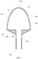
- FIG. 1 is a schematic view of a steam-water separator according to an embodiment of the present application.
- an embodiment of the present application provides a steam-water separator 10, including a separator body 100 and first connecting pipes 200.
- the separator body 100 is provided with a first accommodation cavity 110, and an end of the separator body 100 is provided with a water inlet 120 in communication with the first accommodation cavity 110.
- the separator body 100 is provided with a plurality of first connecting holes 130 in communication with the first accommodation cavity 110, and the plurality of first connecting holes 130 may be evenly spaced apart from each other on the entire surface of the separator body 100.
- the plurality of first connecting holes 130 may also be provided on a part of the surface of the separator body 100.
- a plurality of the first connecting pipes 200 are provided, the number of the first connecting pipes 200 is the same as the number of the first connecting holes 130, and the first connection pipes 200 are connected to the first connecting holes 130 in a one-to-one correspondence.
- An end of the first connecting pipe 200 may be welded to the first connecting hole 130, and an inner diameter of the first connecting pipe 200 may be about 3 cm.
- the steam-water separator 10 is usually immersed in a cold source water pool serving as a heat sink.
- steam-water separator 10 of the embodiment of the present application When the steam-water separator 10 of the embodiment of the present application is in use, steam-water mixture will flow to the water inlet 120 through a hot water outlet pipe of a waste heat removal system, and hot water enters the first accommodation cavity 110 through the water inlet 120.
- the first accommodation cavity 110 is separated from a cold water region outside the separator body 100 through the separator body 100, so that the cavitation phenomenon will not occur in the first accommodation cavity 110. Under the combined action of the obstruction of the separator body 100 and the bubble buoyancy, the steam-water mixture will generate a stratification effect in the first accommodation cavity 110.
- the separator body 100 includes a housing 140 and a bottom plate 150.
- the housing 140 may be semi-ellipsoidal or conical, so as to obtain an ellipsoidal steam-water separator 10 or a conical steam-water separator 10.
- the housing 140 is connected to the bottom plate 150 to enclose the first accommodation cavity 110.
- the water inlet 120 is provided on the bottom plate 150
- the first connecting holes 130 are provided on the housing 140
- the plurality of first connecting holes 130 may be evenly spaced apart from each other on the entire surface of the housing 140.
- the plurality of first connecting holes 130 may also be provided on a part of the surface of the housing 140, and the specific design may be flexible according to the actual situation, which is not limited herein.
- the steam-water separator 10 further includes a second connecting pipe 300, and one end of the second connecting pipe 300 is connected to the water inlet 120.
- the end of the second connecting pipe 300 may be welded to the bottom plate 120, so as to communicate the second connecting pipe 300 with the water inlet 120, and further communicate the second connecting pipe 300 with the first accommodation cavity 110.
- the hot water in the waste heat removal system flows into the first accommodation cavity 110 through the second connecting pipe 300.
- the other end of the second connecting pipe 300 is provided with an internal thread 310, and the hot water pipe in the waste heat removal system can be provided with an external thread, so that the hot water pipe in the waste heat removal system is threadedly connected to the second connecting pipe 300, and finally the steam-water separator 10 of the embodiment of the present application is connected to the waste heat removal system.
- the steam-water separator 10 further includes a reinforcing rib 400 in a shape of a right-angled triangle.
- Two right-angled sides of the reinforcing rib 400 are connected to the bottom plate 150 and the second connecting pipe 300, respectively.
- a surface of the bottom plate 150 is perpendicular to a longitudinal extension direction of the second connecting pipe 300, so that the two right-angle sides of the reinforcing rib 400 are connected to an outer surface of the bottom plate 150 away from the first accommodation cavity 110 and a side surface of the second connecting pipe 300, respectively.
- the two right-angle sides of the reinforcing rib 400 can be welded to the bottom plate 150 and the second connecting pipe 300, respectively.
- the arrangement of the reinforcing rib 400 can increase the structural stability between the bottom plate 150 and the second connecting pipe 300.
- the reinforcing rib 400 is a thin sheet of stainless steel.
- a plurality of reinforcing ribs 400 may be provided, and the plurality of reinforcing ribs 400 may be arranged in an annular array around an axis of the second connecting pipe 300.
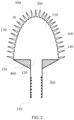
- FIG. 2 is a schematic view of a steam-water separator according to another embodiment of the present application.
- the steam-water separator 10 further includes a plurality of nozzles 500.
- the number of the nozzles 500 is the same as the number of the first connecting pipes 200, and the nozzles 500 are connected to the first connecting pipes 200 in a one-to-one correspondence.
- the nozzle 500 is threadedly connected to the first connecting pipe 200.
- the first connecting pipe 200 is provided with an external thread
- the nozzle 500 is provided with an internal thread, so that the nozzle 500 is fixed to the first connecting pipe 200 by rotating and screwing by means of the threaded connection between the nozzle 500 and the first connecting pipe 200, so as to facilitate removal and replacement of the nozzle 500.
- a sum of opening areas of the plurality of nozzles 500 is greater than a cross-sectional area of the second connecting pipe 300, so as to reduce the overall resistance of the steam-water separator 10 of the embodiment of the present application.
- the opening area of each nozzle 500 sequentially increases from an end thereof away from the housing 140 to an end thereof connected to the housing 140.
- a length of the nozzle 500 can be configured to be about 10 cm.
- a lower half part of the nozzle 500 may be cylindrical, and an upper half part of the nozzle 500 may be conical.
- the opening area of a conical part of the nozzle 500 increases sequentially from the end thereof away from the housing 140 to the end thereof connected to the housing 140.
- the gas at the top portion enters the external environment through the nozzle 500, and the liquid at the lower part also enters the external environment through the nozzle 500.
- the size of the bubble entering the external environment is limited by the inner diameter of the nozzle 500, so that the function of breaking up the larger bubble is achieved, and the cavitation phenomenon is reduced.
- a diameter of a top opening of the nozzle 500 mounted on the top portion of the housing 140 is less than a diameter of the top opening of the nozzle 500 mounted on the bottom portion of the housing 140. That is, as a height of the nozzle 500 on the housing 140 decreases, the diameter of the top opening of the nozzle 500 gradually increases.
- the diameter of the top opening of the nozzle 500 may be configured between 0.5 cm and 2 cm.
- the steam-water separator 10 provided by the embodiment of the present application includes the separator body 100 and the first connecting pipe 200.
- the steam-water separator 10 is usually immersed in a cold source water pool serving as the heat sink.
- the steam-water separator 10 of the embodiment of the present application is in use, the steam-water mixture will flow to the water inlet 120 through a hot water outlet pipe of a waste heat removal system, and hot water enters the first accommodation cavity 110 through the water inlet 120.
- the steam-water mixture generates the stratification effect in the first accommodation cavity 110.
- the lighter gas aggregates at the top portion of the steam-water separator 10, and the heavier liquid aggregates at a lower part of the steam-water separator 10, thereby achieving the separation of the steam-water mixture.
- the gas at the top portion enters an external environment through the first connecting pipe 200 on the separator body 100, and the liquid at the lower part also enters the external environment through the first connecting pipe 200 on the separator body 100.
- the size of the bubble entering the external environment is limited by the inner diameter of the first connecting pipe 200, so that the function of breaking up the larger bubble is achieved, the cavitation phenomenon is reduced, and the problem that the steam-water separator 10 in the prior art cannot reduce the corrosion effect on the pipeline components due to the cavitation phenomenon is finally solved.
- the embodiment of the present application further provides a waste heat removal system, which includes the aforementioned steam-water separator 10.
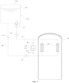
- the waste heat removal system includes a water tank 600, a starting tank 700, an air-cooled heat exchanger 800, and the aforementioned steam-water separator 10.
- the water tank 600 is provided with a second accommodation cavity 610 and a gas outlet 620 in communication with the second accommodation cavity 610.
- the second accommodation cavity 610 is filled with low-temperature cold water, which serves as a heat transfer medium and a cold source for the operation of the waste heat removal system of the embodiment of the present application, and the specific amount of water can be determined according to the requirements of different reactors.
- the steam-water separator 10 is provided in the second accommodation cavity 610.
- the bottom portion of the water tank 600 may be provided with a small sinking pit, a height of the sinking pit is slightly greater than a height of the steam-water separator 10, and a width of the sinking pit is approximately two to three times the maximum width of the steam-water separator 10, so that the steam-water separator 10 may be completely immersed in the sinking pit.
- the waste heat removal system When a water level of the water tank 600 is lower than an outlet of the nozzle 500 at a lowest layer of the steam-water separator 10, the waste heat removal system will stop operating.
- the arrangement of the sinking pit allows the water in the water tank 600 to be fully utilized, with only a small volume of water source remaining in the sinking pit cannot be completely evaporated.
- the starting tank 700 is provided with a third accommodation cavity 710 and a fourth accommodation cavity 720 that are spaced apart.
- the third accommodation cavity 710 is configured to accommodate cooling water
- the fourth accommodation cavity 720 is configured to accommodate high-pressure nitrogen.
- a water inlet end of the air-cooled heat exchanger 800 is in communication with both the second accommodation cavity 610 and the third accommodation cavity 710, and a water outlet end of the air-cooled heat exchanger 800 is in communication with both the first accommodation cavity 110 and the fourth accommodation cavity 720.
- the air-cooled heat exchanger 800 adopts a design of a heat exchange pipe, with cold water on an inner side of the pipe, and the atmosphere of the containment vessel 40 on an outer side of the pipe. Its function is to transfer the energy of the high-temperature gas mixture in the containment vessel 40 to the cold water on the inner side of the heat exchange pipe, so as to heat the cold water on the inner side of the heat exchange pipe.
- the air-cooled heat exchanger 800 may adopt finned heat exchange pipes, and in order to enhance the heat exchange effect, a plurality of air-cooled heat exchangers 800 may be arranged in the containment vessel 40, and the different air-cooled heat exchangers 800 are connected in parallel.
- the waste heat removal system further includes a first control valve 20 and a second control valve 30.
- the first control valve 20 is provided at the water inlet end of the air-cooled heat exchanger 800, so as to control the water inlet end of the air-cooled heat exchanger 800 to be connected to or disconnected from the third accommodation cavity 710.
- the first control valve 20 is opened, the cold water in the third accommodation cavity 710 flows into the air-cooled heat exchanger 800 to increase the heat exchange rate of the air-cooled heat exchanger 800.
- the first control valve 20 is closed, the cold water in the third accommodation cavity 710 cannot flow into the air-cooled heat exchanger 800.
- the second control valve 30 is provided at the water outlet end of the air-cooled heat exchanger 800, so as to control the water outlet end of the air-cooled heat exchanger 800 to be connected to or disconnected from the fourth accommodation cavity 720.
- a high-pressure nitrogen in the fourth accommodation cavity 720 flows out.
- the waste heat removal system further includes a first isolation valve 50, a second isolation valve 60, and a check valve 70.
- One end of the second isolation valve 60 is in communication with the steam-water separator 10
- the other end of the second isolation valve 60 is in communication with both the second control valve 30 and the water outlet end of the air-cooled heat exchanger 800, so as to control the steam-water separator 10 to be connected or disconnect to both the second control valve 30 and the water outlet end of the air-cooled heat exchanger 800.
- One end of the check valve 70 is in communication with the second accommodation cavity 610, and the other end of the check valve 70 is in communication with both the first control valve 20 and the water inlet end of the air-cooled heat exchanger 800.
- Two ends of the first isolating isolation valve 50 are in communication with the second accommodation cavity 610 and a water inlet end of the check valve 70, respectively, so as to control the second accommodation cavity 610 to be connected to or disconnected from the water inlet end of the check valve 70.
- the flow of the cooling water in the heat exchange pipe of the air-cooled heat exchanger 800 is accelerated, which enhances the heat dissipation capacity of the air-cooled heat exchanger 800.
- the heated cooling water flows into the water tank 600 through the steam-water separator 10.
- the first control valve 20 is triggered by a low liquid level signal of the starting tank 700 to be automatically closed, and the second control valve 30 is opened to fill the high-pressure nitrogen in the fourth accommodation cavity 720 of the starting tank 700 into the pipeline. After the nitrogen completely runs out, when the pressure in the starting tank 700 is reduced to a preset pressure value, the second control valve 30 is closed.
- opening degrees of the first control valve 20 and the second control valve 30 can be automatically controlled.
- the opening degree of the first control valve 20 is gradually increased from a small value, so as to maintain a water injection flow rate within a relatively small range to prolong the water injection process.
- the opening degree of the second control valve 30 is gradually increased from a small value, so as to maintain a gas injection flow rate within a relatively small range to prolong the gas injection process.
- the hot water flows through the pipeline and flows into the water tank 600 through the steam-water separator 10.
- the generated water vapor will enter the external atmospheric environment through the gas outlet 620, so that the external atmospheric environment becomes the final heat sink, and the waste heat is discharged to the external environment.
- a temperature of the water in a hot water pipe 90 is higher than a temperature of water in a cold water pipe 80
- a density of the water in the hot water pipe 90 is less than a density of water in the cold water pipe 80, thereby generating a pressure difference between the cold water pipe 80 and the hot water pipe 90, and then the cooling water is driven to circulate along the water tank 600, the cold water pipe 80, the air cooling heat exchanger 800, the hot water pipe 90, and the water tank 600 sequentially.
- an average density of fluid in the hot water pipe 90 will be further reduced, so that the pressure difference between the cold water in the cold water pipe 80 and the hot water in the hot water pipe 90 is increased, that is, a driving force for the flow of the cooling water is increased, a flow velocity of the fluid in the heat exchange pipe of the air-cooled heat exchanger 800 is increased, and the heat exchange capacity of the air-cooled heat exchanger 800 is improved.
- the hot water which is a steam-water mixture, flows into the water tank 600 through the steam-water separator 10.
- the steam-water mixture generates the stratification effect in the steam-water separator 10.
- the lighter gas aggregates at the top portion of the steam-water separator 10, and the heavier liquid aggregates at the lower part of the steam-water separator 10, thereby achieving the separation of the steam-water mixture.
- the larger bubbles in the gas are smashed into small bubbles under the action of the steam-water separator 10, so as to reduce the cavitation phenomenon, and further reduce the corrosion effect of the cavitation phenomenon on the hot water pipeline 90.
- the waste heat removal system provided by the embodiment of the present application is driven by a high-pressure energy storage of the starting tank 700 and a fluid density difference between the cold water pipeline 80 and the hot water pipeline 90, which does not need the input of an active energy, has high safety and reliability, and does not need human intervention.
- the waste heat removal system can continuously remove the heat in the containment vessel 40 after an accident, thus ensuring that the pressure in the containment vessel 40 does not exceed a safety limit, and ensuring that a radioactive material is contained within the containment vessel 40.
- the waste heat removal system provided by the embodiment of the present application includes the aforementioned steam-water separator 10, which includes the separator body 100 and the first connecting pipe 200.
- the hot water in the waste heat removal system flows through the steam-water separator 10, the hot water is the steam-water mixture, and the steam-water mixture generates the stratification effect in the separator body 100.
- the larger bubbles in the gas are limited by the inner diameter of the first connecting pipe 200, so that the function of breaking up the larger bubble is achieved, the cavitation phenomenon is reduced, and the corrosion effect of the cavitation phenomenon on the pipeline in the waste heat removal system is reduced.
Landscapes
- Engineering & Computer Science (AREA)
- Chemical & Material Sciences (AREA)
- Chemical Kinetics & Catalysis (AREA)
- Physics & Mathematics (AREA)
- Thermal Sciences (AREA)
- Mechanical Engineering (AREA)
- General Engineering & Computer Science (AREA)
- High Energy & Nuclear Physics (AREA)
- Water Supply & Treatment (AREA)
- Separating Particles In Gases By Inertia (AREA)
- Physical Water Treatments (AREA)
- Heat-Exchange Devices With Radiators And Conduit Assemblies (AREA)
Abstract
Description
- This application claims priority of
Chinese Patent Application No. 202111306461.8, filed on November 5, 2021 - The present application relates to the technical field of nuclear power, and in particular to a steam-water separator and a waste heat removal system.
- The conventional steam-water separator is located below a dryer and a gravity separation space in a steam generator of a nuclear power plant, and is configured to remove water suspended in steam that cannot be discharged through a steam trap. Generally, the steam-water separator used in a steam system is only suitable for working conditions of steam saturation state, and does not have the function of breaking up large bubbles, thus the corrosion effect of cavitation on the pipeline components cannot be reduced.
- According to various exemplary embodiments of the present application, a steam-water separator and a waste heat removal system are provided.
- A steam-water separator is provided according to the embodiment of the present application provides, which includes a separator body provided with a first accommodation cavity, an end of the separator body being provided with a water inlet in communication with the first accommodation cavity, and the separator body being provided with a plurality of first connecting holes in communication with the first accommodation cavity; and a plurality of first connecting pipes, the number of the first connecting pipes is the same as the number of the first connecting holes, and the first connecting pipes are connected to the first connecting holes in a one-to-one correspondence.
- In one of the embodiments, the separator body includes a housing and a bottom plate, the housing is connected to the bottom plate to enclose the first accommodation cavity, the water inlet is provided on the bottom plate, the first connecting holes are provided on the housing.
- In one of the embodiments, the steam-water separator further includes a second connecting pipe, one end of the second connecting pipe is connected to the water inlet, and the other end of the second connecting pipe is provided with an internal thread.
- In one of the embodiments, the steam-water separator further includes a reinforcing rib, the reinforcing rib is in a shape of a right-angled triangle, and two right-angled sides of the reinforcing rib are connected to the bottom plate and the second connecting pipe, respectively
- In one of the embodiments, a plurality of reinforcing ribs are provided, and the plurality of reinforcing ribs are arranged in an annular array around an axis of the second connecting pipe.
- In one of the embodiments, the steam-water separator further includes a plurality of nozzles, the number of the nozzles is the same as the number of the first connecting pipes, and the nozzles are connected to the first connecting pipes in a one-to-one correspondence.
- In one of the embodiments, the plurality of nozzles are threadedly connected to the first connecting pipes.
- In one of the embodiments, a sum of opening areas of the plurality of nozzles is greater than a cross-sectional area of the second connecting pipe.
- In one of the embodiments, an opening area of each nozzle sequentially increases from an end thereof away from the housing to an end thereof connected to the housing.
- In one of the embodiments, a diameter of a top opening of the nozzle located at a top portion of the housing is less than a diameter of a top opening of the nozzle located at a bottom portion of the housing.
- A waste heat removal system is further provided according to the embodiment of the present application, which includes the aforementioned steam-water separator.
- In one of the embodiments, the waste heat removal system further includes a water tank provided with a second accommodation cavity and a gas outlet in communication with the second accommodation cavity, and the steam-water separator being provided in the second accommodation cavity; a starting box provided with a third accommodation cavity and a fourth accommodation cavity that are spaced apart, the third accommodation cavity being configured to accommodate cooling water, and the fourth accommodation cavity being configured to accommodate high-pressure nitrogen; and an air-cooled heat exchanger, wherein a water inlet end of the air-cooled heat exchanger is in communication with both the second accommodation cavity and the third accommodation cavity, and a water outlet end of the air-cooled heat exchanger is in communication with both the first accommodation cavity and the fourth accommodation cavity.
- In one of the embodiments, the waste heat removal system further includes a first control valve provided at the water inlet end of the air-cooled heat exchanger and configured to control the water inlet end of the air-cooled heat exchanger to be connected to or disconnected from the third accommodation cavity; and a second control valve provided at the water outlet end of the air-cooled heat exchanger to control the water outlet end of the air-cooled heat exchanger to be connected to or disconnected from the fourth accommodation cavity.
- In one of the embodiments, he waste heat removal system further includes a second isolation valve, wherein one end of the second isolation valve is in communication with the steam-water separator, and the other end of the second isolation valve is in communication with both the second control valve and the water outlet end of the air-cooled heat exchanger; a check valve, wherein one end of the check valve is in communication with the second accommodation cavity, and the other end of the check valve is in communication with both the first control valve and the water inlet end of the air-cooled heat exchanger; and a first isolation valve, wherein both ends of the first isolation valve are in communication with the second accommodation cavity and a water inlet end of the check valve, respectively.
- The steam-water separator and the waste heat derivation system of the present applicant includes the separator body and the first connecting pipe. The separator body is provided with the first accommodation cavity, the end of the separator body is provided with the water inlet in communication with the first accommodation cavity, and the separator body is provided with the plurality of first connecting holes in communication with the first accommodation cavity. The plurality of first connecting pipes are provided, the number of the first connecting pipes is the same as the number of the first connecting holes, and the first connecting pipes are connected to the first connecting holes in a one-to-one correspondence. When the steam-water separator is in use, steam-water mixture enters the first accommodation cavity, and the first accommodation cavity is separated from a cold water region outside the separator body through the separator body, so that the cavitation phenomenon will not occur in the first accommodation cavity. Under the combined action of the obstruction of the separator body and the bubble buoyancy, the steam-water mixture will generate a stratification effect in the first accommodation cavity. Lighter gas aggregates at the top portion of the steam-water separator, and heavier liquid aggregates at a lower part of the steam-water separator, thereby achieving the separation of the steam-water mixture. Meanwhile, the gas at the top enters an external environment through the first connecting pipe on the separator body, and the liquid at the lower part also enters the external environment through the first connecting pipe on the separator body. A size of the bubble entering the external environment is limited by the inner diameter of the first connecting pipe, so that the function of breaking up the larger bubble is achieved, the cavitation phenomenon is reduced, and the problem that the steam-water separator in the prior art cannot reduce the corrosion effect on the pipeline components due to the cavitation phenomenon is finally solved.
- In order to illustrate the embodiments of the present disclosure more clearly, the drawings used in the embodiments will be described briefly. Apparently, the following described drawings are merely for the embodiments of the present disclosure, and other drawings can be derived by those of ordinary skill in the art without any creative effort.
-
FIG. 1 is a schematic view of a steam-water separator according to an embodiment of the present application. -
FIG. 2 is a schematic view of a steam-water separator according to another embodiment of the present application. -
FIG. 3 is a block diagram of a waste heat removal system according to an embodiment of the present application. - In order to make the above obj ects, features and advantages of the present disclosure clear and easier to understand, the specific embodiments of the present disclosure are described in detail below in combination with the accompanying drawings. Many specific details are set forth in the following description to facilitate a full understanding of the present disclosure. However, the present disclosure can be implemented in many ways different from those described herein, and those skilled in the art can make similar improvements without departing from the connotation of the present disclosure. Therefore, the present disclosure is not limited by the specific embodiments disclosed below.
- In the description of the present disclosure, it should be understood that the terms "center", "longitudinal", "transverse", "length", "width", "thickness", "upper", "lower", "front", "rear", "left", "right", "vertical", "horizontal", "top", "bottom", "inner", "outer", "clockwise", "counterclockwise", "axial", "radial", "circumferential direction" are based on the azimuth or position relationship shown in the attached drawings, which are only for the convenience of describing the present disclosure and simplifying the description, rather than indicating or implying that the device or element must have a specific azimuth, be constructed and operated in a specific azimuth, so such terms cannot be understood as a limitation of the present disclosure.
- In addition, the terms "first" and "second" are only used for descriptive purposes and cannot be understood as indicating or implying relative importance or implicitly indicating the number of indicated technical features. Thus, the features defined with "first" and "second" may explicitly or implicitly include at least one of the features. In the description of the present disclosure, "a plurality of' means at least two, such as two, three, etc., unless otherwise expressly and specifically defined.
- In the present disclosure, unless otherwise expressly specified and limited, the terms "mount", "connect", "contact", "fix" and other terms should be understood in a broad sense, for example, they can be fixed connections, detachable connections, or integrated. They can be mechanical connection or electrical connection. They can be directly connected or indirectly connected through an intermediate medium. They can be the connection within two elements or the interaction relationship between two elements, unless otherwise expressly limited. For those skilled in the art, the specific meaning of the above terms in the present disclosure can be understood according to the specific situation.
- In the present disclosure, unless otherwise expressly specified and limited, the first feature "above" or "below" the second feature may be in direct contact with the first and second features, or the first and second features may be in indirect contact through an intermediate medium. Moreover, the first feature is "above" the second feature, but the first feature is directly above or diagonally above the second feature, or it only means that the horizontal height of the first feature is higher than the second feature. The first feature is "below" of the second feature, which can mean that the first feature is directly below or obliquely below the second feature, or simply that the horizontal height of the first feature is less than that of the second feature.
- It should be noted that when an element is called "fixed to" or "provided on" another element, it can be directly on another element or there can be a centered element. When an element is considered to be "connected" to another element, it can be directly connected to another element or there may be intermediate elements at the same time. The terms "vertical", "horizontal", "up", "down", "left", "right" and similar expressions used herein are for the purpose of illustration only and do not represent the only embodiment.
- The steam-water separator in the prior art is mainly divided into the following three types:
Baffle type: A baffle or folded plate separator is composed of many baffles. The fluid changes its flow direction many times in the separator. Due to the large mass and inertia of suspended water droplets, when the flow direction changes at the baffle, the dry steam can bypass the baffle and continue to move forward, while the water droplets will accumulate on the baffle. The steam-water separator has a large flow area, which reduces the kinetic energy of water droplets, most of which will condense and finally fall to a bottom portion of the separator and be discharged through a steam trap. - Vapor cyclone Type: Vapor cyclone or centrifugal separators use a series of fins to create a high velocity cyclone that spins a flowing steam at high velocity in the separator.
- Adsorption type: There is an obstacle, usually a metal mesh pad, on a steam channel inside an adsorption type separator. When encountering the obstacle, the suspended water droplets are adsorbed. When the water droplets are large to a certain extent, they fall to a bottom portion of the separator due to gravity.
- The above types of steam-water separators are only suitable for working conditions of steam saturation state, and do not have the function of breaking up large bubbles, thus the corrosion effect of cavitation on the pipeline components cannot be reduced.
-
FIG. 1 is a schematic view of a steam-water separator according to an embodiment of the present application. - As shown in
FIG. 1 , an embodiment of the present application provides a steam-water separator 10, including aseparator body 100 and first connectingpipes 200. Theseparator body 100 is provided with afirst accommodation cavity 110, and an end of theseparator body 100 is provided with awater inlet 120 in communication with thefirst accommodation cavity 110. Theseparator body 100 is provided with a plurality of first connectingholes 130 in communication with thefirst accommodation cavity 110, and the plurality of first connectingholes 130 may be evenly spaced apart from each other on the entire surface of theseparator body 100. In other embodiments, in order to ensure the overall rigidity of theseparator body 100, the plurality of first connectingholes 130 may also be provided on a part of the surface of theseparator body 100. A plurality of the first connectingpipes 200 are provided, the number of the first connectingpipes 200 is the same as the number of the first connectingholes 130, and thefirst connection pipes 200 are connected to the first connectingholes 130 in a one-to-one correspondence. An end of the first connectingpipe 200 may be welded to the first connectinghole 130, and an inner diameter of the first connectingpipe 200 may be about 3 cm. - In use, the steam-
water separator 10 is usually immersed in a cold source water pool serving as a heat sink. When the steam-water separator 10 of the embodiment of the present application is in use, steam-water mixture will flow to thewater inlet 120 through a hot water outlet pipe of a waste heat removal system, and hot water enters thefirst accommodation cavity 110 through thewater inlet 120. Thefirst accommodation cavity 110 is separated from a cold water region outside theseparator body 100 through theseparator body 100, so that the cavitation phenomenon will not occur in thefirst accommodation cavity 110. Under the combined action of the obstruction of theseparator body 100 and the bubble buoyancy, the steam-water mixture will generate a stratification effect in thefirst accommodation cavity 110. Lighter gas aggregates at a top portion of the steam-water separator 10, and heavier liquid aggregates at a lower part of the steam-water separator 10, thereby achieving the separation of the steam-water mixture. Meanwhile, the gas at the top portion enters an external environment through the first connectingpipe 200 on theseparator body 100, and the liquid at the lower part also enters the external environment through the first connectingpipe 200 on theseparator body 100. A size of the bubble entering the external environment is limited by the inner diameter of the first connectingpipe 200, so that the function of breaking up the larger bubble is achieved, the cavitation phenomenon is reduced, and the problem that the steam-water separator 10 in the prior art cannot reduce the corrosion effect on the pipeline components due to the cavitation phenomenon is finally solved. - In some embodiments, the
separator body 100 includes ahousing 140 and abottom plate 150. Thehousing 140 may be semi-ellipsoidal or conical, so as to obtain an ellipsoidal steam-water separator 10 or a conical steam-water separator 10. Thehousing 140 is connected to thebottom plate 150 to enclose thefirst accommodation cavity 110. Thewater inlet 120 is provided on thebottom plate 150, the first connectingholes 130 are provided on thehousing 140, and the plurality of first connectingholes 130 may be evenly spaced apart from each other on the entire surface of thehousing 140. In other embodiments, in order to ensure the overall rigidity of thehousing 140, the plurality of first connectingholes 130 may also be provided on a part of the surface of thehousing 140, and the specific design may be flexible according to the actual situation, which is not limited herein. - In order to facilitate the connection to the hot water pipe of the waste heat removal system, in some embodiments, the steam-
water separator 10 further includes a second connectingpipe 300, and one end of the second connectingpipe 300 is connected to thewater inlet 120. Specifically, the end of the second connectingpipe 300 may be welded to thebottom plate 120, so as to communicate the second connectingpipe 300 with thewater inlet 120, and further communicate the second connectingpipe 300 with thefirst accommodation cavity 110. During use, the hot water in the waste heat removal system flows into thefirst accommodation cavity 110 through the second connectingpipe 300. The other end of the second connectingpipe 300 is provided with aninternal thread 310, and the hot water pipe in the waste heat removal system can be provided with an external thread, so that the hot water pipe in the waste heat removal system is threadedly connected to the second connectingpipe 300, and finally the steam-water separator 10 of the embodiment of the present application is connected to the waste heat removal system. - In some embodiments, the steam-
water separator 10 further includes a reinforcingrib 400 in a shape of a right-angled triangle. Two right-angled sides of the reinforcingrib 400 are connected to thebottom plate 150 and the second connectingpipe 300, respectively. Specifically, a surface of thebottom plate 150 is perpendicular to a longitudinal extension direction of the second connectingpipe 300, so that the two right-angle sides of the reinforcingrib 400 are connected to an outer surface of thebottom plate 150 away from thefirst accommodation cavity 110 and a side surface of the second connectingpipe 300, respectively. The two right-angle sides of the reinforcingrib 400 can be welded to thebottom plate 150 and the second connectingpipe 300, respectively. The arrangement of the reinforcingrib 400 can increase the structural stability between thebottom plate 150 and the second connectingpipe 300. In other embodiments, the reinforcingrib 400 is a thin sheet of stainless steel. A plurality of reinforcingribs 400 may be provided, and the plurality of reinforcingribs 400 may be arranged in an annular array around an axis of the second connectingpipe 300. -
FIG. 2 is a schematic view of a steam-water separator according to another embodiment of the present application. - As shown in
FIG. 2 , in another embodiment, in order to enable the gas in thefirst accommodation cavity 110 to be ejected farther, the steam-water separator 10 further includes a plurality ofnozzles 500. The number of thenozzles 500 is the same as the number of the first connectingpipes 200, and thenozzles 500 are connected to the first connectingpipes 200 in a one-to-one correspondence. Thenozzle 500 is threadedly connected to the first connectingpipe 200. Specifically, the first connectingpipe 200 is provided with an external thread, and thenozzle 500 is provided with an internal thread, so that thenozzle 500 is fixed to the first connectingpipe 200 by rotating and screwing by means of the threaded connection between thenozzle 500 and the first connectingpipe 200, so as to facilitate removal and replacement of thenozzle 500. - A sum of opening areas of the plurality of
nozzles 500 is greater than a cross-sectional area of the second connectingpipe 300, so as to reduce the overall resistance of the steam-water separator 10 of the embodiment of the present application. The opening area of eachnozzle 500 sequentially increases from an end thereof away from thehousing 140 to an end thereof connected to thehousing 140. A length of thenozzle 500 can be configured to be about 10 cm. In another embodiment, a lower half part of thenozzle 500 may be cylindrical, and an upper half part of thenozzle 500 may be conical. The opening area of a conical part of thenozzle 500 increases sequentially from the end thereof away from thehousing 140 to the end thereof connected to thehousing 140. After the hot water enters thefirst accommodation cavity 110 to generate the stratification effect, the gas at the top portion enters the external environment through thenozzle 500, and the liquid at the lower part also enters the external environment through thenozzle 500. The size of the bubble entering the external environment is limited by the inner diameter of thenozzle 500, so that the function of breaking up the larger bubble is achieved, and the cavitation phenomenon is reduced. - In addition, in order to improve the steam-water separation efficiency, a diameter of a top opening of the
nozzle 500 mounted on the top portion of thehousing 140 is less than a diameter of the top opening of thenozzle 500 mounted on the bottom portion of thehousing 140. That is, as a height of thenozzle 500 on thehousing 140 decreases, the diameter of the top opening of thenozzle 500 gradually increases. The diameter of the top opening of thenozzle 500 may be configured between 0.5 cm and 2 cm. - The steam-
water separator 10 provided by the embodiment of the present application includes theseparator body 100 and the first connectingpipe 200. In use, the steam-water separator 10 is usually immersed in a cold source water pool serving as the heat sink. When the steam-water separator 10 of the embodiment of the present application is in use, the steam-water mixture will flow to thewater inlet 120 through a hot water outlet pipe of a waste heat removal system, and hot water enters thefirst accommodation cavity 110 through thewater inlet 120. The steam-water mixture generates the stratification effect in thefirst accommodation cavity 110. The lighter gas aggregates at the top portion of the steam-water separator 10, and the heavier liquid aggregates at a lower part of the steam-water separator 10, thereby achieving the separation of the steam-water mixture. Meanwhile, the gas at the top portion enters an external environment through the first connectingpipe 200 on theseparator body 100, and the liquid at the lower part also enters the external environment through the first connectingpipe 200 on theseparator body 100. The size of the bubble entering the external environment is limited by the inner diameter of the first connectingpipe 200, so that the function of breaking up the larger bubble is achieved, the cavitation phenomenon is reduced, and the problem that the steam-water separator 10 in the prior art cannot reduce the corrosion effect on the pipeline components due to the cavitation phenomenon is finally solved. -
FIG. 3 is a block diagram of a waste heat removal system according to an embodiment of the present application. - As shown in
FIG. 3 , the embodiment of the present application further provides a waste heat removal system, which includes the aforementioned steam-water separator 10. In one embodiment, the waste heat removal system includes awater tank 600, astarting tank 700, an air-cooledheat exchanger 800, and the aforementioned steam-water separator 10. Thewater tank 600 is provided with asecond accommodation cavity 610 and agas outlet 620 in communication with thesecond accommodation cavity 610. Thesecond accommodation cavity 610 is filled with low-temperature cold water, which serves as a heat transfer medium and a cold source for the operation of the waste heat removal system of the embodiment of the present application, and the specific amount of water can be determined according to the requirements of different reactors. When the cold water in thewater tank 600 boils, the generated water vapor will enter the external atmospheric environment through thegas outlet 620, so that the external atmospheric environment becomes the final heat sink, and the waste heat is discharged to the external environment. The steam-water separator 10 is provided in thesecond accommodation cavity 610. In some embodiments, the bottom portion of thewater tank 600 may be provided with a small sinking pit, a height of the sinking pit is slightly greater than a height of the steam-water separator 10, and a width of the sinking pit is approximately two to three times the maximum width of the steam-water separator 10, so that the steam-water separator 10 may be completely immersed in the sinking pit. When a water level of thewater tank 600 is lower than an outlet of thenozzle 500 at a lowest layer of the steam-water separator 10, the waste heat removal system will stop operating. The arrangement of the sinking pit allows the water in thewater tank 600 to be fully utilized, with only a small volume of water source remaining in the sinking pit cannot be completely evaporated. - The starting
tank 700 is provided with athird accommodation cavity 710 and afourth accommodation cavity 720 that are spaced apart. Thethird accommodation cavity 710 is configured to accommodate cooling water, and thefourth accommodation cavity 720 is configured to accommodate high-pressure nitrogen. A water inlet end of the air-cooledheat exchanger 800 is in communication with both thesecond accommodation cavity 610 and thethird accommodation cavity 710, and a water outlet end of the air-cooledheat exchanger 800 is in communication with both thefirst accommodation cavity 110 and thefourth accommodation cavity 720. - The air-cooled
heat exchanger 800 adopts a design of a heat exchange pipe, with cold water on an inner side of the pipe, and the atmosphere of thecontainment vessel 40 on an outer side of the pipe. Its function is to transfer the energy of the high-temperature gas mixture in thecontainment vessel 40 to the cold water on the inner side of the heat exchange pipe, so as to heat the cold water on the inner side of the heat exchange pipe. In order to increase a heat exchange area of the air-cooledheat exchanger 800, the air-cooledheat exchanger 800 may adopt finned heat exchange pipes, and in order to enhance the heat exchange effect, a plurality of air-cooledheat exchangers 800 may be arranged in thecontainment vessel 40, and the different air-cooledheat exchangers 800 are connected in parallel. - In some embodiments, the waste heat removal system further includes a
first control valve 20 and asecond control valve 30. Thefirst control valve 20 is provided at the water inlet end of the air-cooledheat exchanger 800, so as to control the water inlet end of the air-cooledheat exchanger 800 to be connected to or disconnected from thethird accommodation cavity 710. When thefirst control valve 20 is opened, the cold water in thethird accommodation cavity 710 flows into the air-cooledheat exchanger 800 to increase the heat exchange rate of the air-cooledheat exchanger 800. When thefirst control valve 20 is closed, the cold water in thethird accommodation cavity 710 cannot flow into the air-cooledheat exchanger 800. Thesecond control valve 30 is provided at the water outlet end of the air-cooledheat exchanger 800, so as to control the water outlet end of the air-cooledheat exchanger 800 to be connected to or disconnected from thefourth accommodation cavity 720. When thesecond control valve 30 is opened, a high-pressure nitrogen in thefourth accommodation cavity 720 flows out. - In some embodiments, in order to conveniently control the pipeline circulation in the waste heat removal system provided by the embodiment of the present application, the waste heat removal system further includes a
first isolation valve 50, asecond isolation valve 60, and acheck valve 70. One end of thesecond isolation valve 60 is in communication with the steam-water separator 10, the other end of thesecond isolation valve 60 is in communication with both thesecond control valve 30 and the water outlet end of the air-cooledheat exchanger 800, so as to control the steam-water separator 10 to be connected or disconnect to both thesecond control valve 30 and the water outlet end of the air-cooledheat exchanger 800. One end of thecheck valve 70 is in communication with thesecond accommodation cavity 610, and the other end of thecheck valve 70 is in communication with both thefirst control valve 20 and the water inlet end of the air-cooledheat exchanger 800. Two ends of the first isolatingisolation valve 50 are in communication with thesecond accommodation cavity 610 and a water inlet end of thecheck valve 70, respectively, so as to control thesecond accommodation cavity 610 to be connected to or disconnected from the water inlet end of thecheck valve 70. - In an initial state of the waste heat removal system provided by the embodiment of the present application, all the valves in the system are closed, the pipeline and the air-cooled
heat exchanger 800 are filled with cold water, and the waste heat removal system is opened by a high atmospheric pressure signal of thecontainment vessel 40. When the ambient pressure reaches a preset value, thefirst isolation valve 50, thesecond isolation valve 60, and thefirst control valve 20 are opened respectively, and the cold water in thesecond accommodation cavity 610 and the cold water in thestarting tank 700 both flow into the air-cooledheat exchanger 800 through the pipeline. Driven by the cold water in thestarting tank 700, the flow of the cooling water in the heat exchange pipe of the air-cooledheat exchanger 800 is accelerated, which enhances the heat dissipation capacity of the air-cooledheat exchanger 800. The heated cooling water flows into thewater tank 600 through the steam-water separator 10. When the cold water in thestarting tank 700 completely runs out, thefirst control valve 20 is triggered by a low liquid level signal of thestarting tank 700 to be automatically closed, and thesecond control valve 30 is opened to fill the high-pressure nitrogen in thefourth accommodation cavity 720 of thestarting tank 700 into the pipeline. After the nitrogen completely runs out, when the pressure in thestarting tank 700 is reduced to a preset pressure value, thesecond control valve 30 is closed. During this process, opening degrees of thefirst control valve 20 and thesecond control valve 30 can be automatically controlled. During the water injection process, the opening degree of thefirst control valve 20 is gradually increased from a small value, so as to maintain a water injection flow rate within a relatively small range to prolong the water injection process. During the gas injection process, the opening degree of thesecond control valve 30 is gradually increased from a small value, so as to maintain a gas injection flow rate within a relatively small range to prolong the gas injection process. - After the cold water flowing into the air-cooled
heat exchanger 800 is heated by the air-cooledheat exchanger 800, the hot water flows through the pipeline and flows into thewater tank 600 through the steam-water separator 10. When the cold water in thewater tank 600 boils, the generated water vapor will enter the external atmospheric environment through thegas outlet 620, so that the external atmospheric environment becomes the final heat sink, and the waste heat is discharged to the external environment. During this process, since a temperature of the water in ahot water pipe 90 is higher than a temperature of water in acold water pipe 80, a density of the water in thehot water pipe 90 is less than a density of water in thecold water pipe 80, thereby generating a pressure difference between thecold water pipe 80 and thehot water pipe 90, and then the cooling water is driven to circulate along thewater tank 600, thecold water pipe 80, the aircooling heat exchanger 800, thehot water pipe 90, and thewater tank 600 sequentially. After the nitrogen in thestarting tank 700 is injected into thehot water pipe 90, an average density of fluid in thehot water pipe 90 will be further reduced, so that the pressure difference between the cold water in thecold water pipe 80 and the hot water in thehot water pipe 90 is increased, that is, a driving force for the flow of the cooling water is increased, a flow velocity of the fluid in the heat exchange pipe of the air-cooledheat exchanger 800 is increased, and the heat exchange capacity of the air-cooledheat exchanger 800 is improved. - The hot water, which is a steam-water mixture, flows into the
water tank 600 through the steam-water separator 10. The steam-water mixture generates the stratification effect in the steam-water separator 10. The lighter gas aggregates at the top portion of the steam-water separator 10, and the heavier liquid aggregates at the lower part of the steam-water separator 10, thereby achieving the separation of the steam-water mixture. Meanwhile, the larger bubbles in the gas are smashed into small bubbles under the action of the steam-water separator 10, so as to reduce the cavitation phenomenon, and further reduce the corrosion effect of the cavitation phenomenon on thehot water pipeline 90. - The waste heat removal system provided by the embodiment of the present application is driven by a high-pressure energy storage of the
starting tank 700 and a fluid density difference between thecold water pipeline 80 and thehot water pipeline 90, which does not need the input of an active energy, has high safety and reliability, and does not need human intervention. The waste heat removal system can continuously remove the heat in thecontainment vessel 40 after an accident, thus ensuring that the pressure in thecontainment vessel 40 does not exceed a safety limit, and ensuring that a radioactive material is contained within thecontainment vessel 40. - The waste heat removal system provided by the embodiment of the present application includes the aforementioned steam-
water separator 10, which includes theseparator body 100 and the first connectingpipe 200. The hot water in the waste heat removal system flows through the steam-water separator 10, the hot water is the steam-water mixture, and the steam-water mixture generates the stratification effect in theseparator body 100. The lighter gas aggregates at the top portion of theseparator body 100, and the heavier liquid aggregates at the lower part of theseparator body 100, thereby achieving the separation of the steam-water mixture. Meanwhile, the larger bubbles in the gas are limited by the inner diameter of the first connectingpipe 200, so that the function of breaking up the larger bubble is achieved, the cavitation phenomenon is reduced, and the corrosion effect of the cavitation phenomenon on the pipeline in the waste heat removal system is reduced. - The above-mentioned embodiments do not constitute a limitation on the protection scope of the technical solution. Any modifications, equivalent replacements and improvements made within the spirit and principles of the above-mentioned embodiments shall be included within the protection scope of this technical solution.
- The foregoing descriptions are merely specific embodiments of the present disclosure, but are not intended to limit the protection scope of the present disclosure. Any variation or replacement readily figured out by a person skilled in the art within the technical scope disclosed in the present disclosure shall all fall within the protection scope of the present disclosure.
Claims (14)
- A steam-water separator, comprising:a separator body provided with a first accommodation cavity, an end of the separator body being provided with a water inlet in communication with the first accommodation cavity, andthe separator body being provided with a plurality of first connecting holes in communication with the first accommodation cavity; anda plurality of first connecting pipes, wherein the number of the first connecting pipes is the same as the number of the first connecting holes, and the first connecting pipes are connected to the first connecting holes in a one-to-one correspondence.
- The steam-water separator according to claim 1, wherein the separator body comprises a housing and a bottom plate, the housing is connected to the bottom plate to enclose the first accommodation cavity, the water inlet is provided on the bottom plate, the first connecting holes are provided on the housing.
- The steam-water separator according to claim 2, further comprising a second connecting pipe, wherein one end of the second connecting pipe is connected to the water inlet, and the other end of the second connecting pipe is provided with an internal thread.
- The steam-water separator according to claim 3, further comprising a reinforcing rib, wherein the reinforcing rib is in a shape of a right-angled triangle, and two right-angled sides of the reinforcing rib are connected to the bottom plate and the second connecting pipe, respectively.
- The steam-water separator according to claim 4, wherein a plurality of reinforcing ribs are provided, and the plurality of reinforcing ribs are arranged in an annular array around an axis of the second connecting pipe.
- The steam-water separator according to claim 3, further comprising a plurality of nozzles, wherein the number of the nozzles is the same as the number of the first connecting pipes, and the nozzles are connected to the first connecting pipes in a one-to-one correspondence.
- The steam-water separator according to claim 6, wherein the plurality of nozzles are threadedly connected to the first connecting pipes.
- The steam-water separator according to claim 6, wherein a sum of opening areas of the plurality of nozzles is greater than a cross-sectional area of the second connecting pipe.
- The steam-water separator according to claim 6, wherein an opening area of each nozzle sequentially increases from an end thereof away from the housing to an end thereof connected to the housing.
- The steam-water separator according to claim 6, wherein a diameter of a top opening of the nozzle located at a top portion of the housing is less than a diameter of a top opening of the nozzle located at a bottom portion of the housing.
- A waste heat removal system comprising the steam-water separator according to any one of claims 1 to 10.
- The waste heat removal system according to claim 11, further comprising:a water tank provided with a second accommodation cavity and a gas outlet in communication with the second accommodation cavity, and the steam-water separator being provided in the second accommodation cavity;a starting box provided with a third accommodation cavity and a fourth accommodation cavity that are spaced apart, the third accommodation cavity being configured to accommodate cooling water, and the fourth accommodation cavity being configured to accommodate high-pressure nitrogen; andan air-cooled heat exchanger, wherein a water inlet end of the air-cooled heat exchanger is in communication with both the second accommodation cavity and the third accommodation cavity, and a water outlet end of the air-cooled heat exchanger is in communication with both the first accommodation cavity and the fourth accommodation cavity.
- The waste heat removal system according to claim 12, further comprising:a first control valve provided at the water inlet end of the air-cooled heat exchanger andconfigured to control the water inlet end of the air-cooled heat exchanger to be connected to ordisconnected from the third accommodation cavity; anda second control valve provided at the water outlet end of the air-cooled heat exchanger andconfigured to control the water outlet end of the air-cooled heat exchanger to be connected to or disconnected from the fourth accommodation cavity.
- The waste heat removal system according to claim 13, further comprising:a second isolation valve, wherein one end of the second isolation valve is in communication with the steam-water separator, and the other end of the second isolation valve is in communication with both the second control valve and the water outlet end of the air-cooled heat exchanger;a check valve, wherein one end of the check valve is in communication with the second accommodation cavity, and the other end of the check valve is in communication with both the first control valve and the water inlet end of the air-cooled heat exchanger; anda first isolation valve, wherein both ends of the first isolation valve are in communication with the second accommodation cavity and a water inlet end of the check valve, respectively.
Applications Claiming Priority (2)
| Application Number | Priority Date | Filing Date | Title |
|---|---|---|---|
| CN202111306461.8A CN114082247B (en) | 2021-11-05 | 2021-11-05 | Steam-water separator and waste heat export system |
| PCT/CN2022/071567 WO2023077674A1 (en) | 2021-11-05 | 2022-01-12 | Steam-water separator and waste heat removal system |
Publications (2)
| Publication Number | Publication Date |
|---|---|
| EP4427830A1 true EP4427830A1 (en) | 2024-09-11 |
| EP4427830A4 EP4427830A4 (en) | 2025-03-26 |
Family
ID=80299139
Family Applications (1)
| Application Number | Title | Priority Date | Filing Date |
|---|---|---|---|
| EP22888715.4A Pending EP4427830A4 (en) | 2021-11-05 | 2022-01-12 | STEAM-WATER SEPARATOR AND WASTE HEAT UTILIZATION SYSTEM |
Country Status (3)
| Country | Link |
|---|---|
| EP (1) | EP4427830A4 (en) |
| CN (1) | CN114082247B (en) |
| WO (1) | WO2023077674A1 (en) |
Families Citing this family (1)
| Publication number | Priority date | Publication date | Assignee | Title |
|---|---|---|---|---|
| CN118089428B (en) * | 2024-03-05 | 2025-04-08 | 水利部节约用水促进中心 | Water recovery system and method |
Family Cites Families (18)
| Publication number | Priority date | Publication date | Assignee | Title |
|---|---|---|---|---|
| GB1286629A (en) * | 1969-03-04 | 1972-08-23 | Atomic Energy Authority Uk | Nuclear reactors |
| DE3728834A1 (en) * | 1987-08-28 | 1989-03-09 | Gostev Dmitrij G | System for condensate removal |
| US5075074A (en) * | 1990-05-29 | 1991-12-24 | General Electric Company | Steam-water separating system for boiling water nuclear reactors |
| JP5285212B2 (en) * | 2006-03-02 | 2013-09-11 | 三菱重工業株式会社 | Steam separator |
| JP5550318B2 (en) * | 2009-12-10 | 2014-07-16 | 三菱重工業株式会社 | Multistage air-water separator and air-water separator |
| CN102522127B (en) * | 2011-12-23 | 2014-07-30 | 中国核电工程有限公司 | Passive containment thermal conduction system |
| CN102637464A (en) * | 2012-03-30 | 2012-08-15 | 中国核电工程有限公司 | Strengthened heat exchange method and device of double-layer concrete containment passive heat derived system |
| CN202555092U (en) * | 2012-04-01 | 2012-11-28 | 天蓬集团有限公司 | Steam-water separator |
| JP5911762B2 (en) * | 2012-06-29 | 2016-04-27 | 株式会社東芝 | Nuclear plant and static containment cooling system |
| CN103778976A (en) * | 2012-10-22 | 2014-05-07 | 中国核动力研究设计院 | Passive waste heat discharging system on secondary side of steam generator |
| CN106205751B (en) * | 2016-08-31 | 2018-03-13 | 长江勘测规划设计研究有限责任公司 | A kind of underground nuclear power station containment latent heat formula cooling system |
| CN106499905B (en) * | 2016-11-25 | 2018-02-16 | 中国核动力研究设计院 | A kind of vehicle repair major water hammer alleviation device for being arranged on pipeline and container link position |
| CN207056134U (en) * | 2017-06-09 | 2018-03-02 | 中广核工程有限公司 | Steam-water separator |
| CN107644693B (en) * | 2017-08-01 | 2019-08-09 | 中广核研究院有限公司 | Passive waste heat removal system for secondary side of marine reactor and once-through steam generator |
| CN108877967B (en) * | 2018-06-25 | 2021-12-07 | 哈尔滨工程大学 | External heat exchange water tank of passive containment cooling system of set formula |
| CN210837199U (en) * | 2019-10-22 | 2020-06-23 | 华龙国际核电技术有限公司 | Waste heat discharge system and nuclear power system |
| KR102249809B1 (en) * | 2019-11-15 | 2021-05-10 | 한국원자력연구원 | Long-term cooling system in nuclear plant and method using the same |
| CN211400403U (en) * | 2019-12-30 | 2020-09-01 | 北京市京科伦冷冻设备有限公司 | Gas-liquid separator |
-
2021
- 2021-11-05 CN CN202111306461.8A patent/CN114082247B/en active Active
-
2022
- 2022-01-12 EP EP22888715.4A patent/EP4427830A4/en active Pending
- 2022-01-12 WO PCT/CN2022/071567 patent/WO2023077674A1/en not_active Ceased
Also Published As
| Publication number | Publication date |
|---|---|
| CN114082247B (en) | 2023-02-03 |
| WO2023077674A1 (en) | 2023-05-11 |
| CN114082247A (en) | 2022-02-25 |
| EP4427830A4 (en) | 2025-03-26 |
Similar Documents
| Publication | Publication Date | Title |
|---|---|---|
| JP6277322B2 (en) | PCV cooling system, and PCV / reactor pressure vessel joint cooling system | |
| CN106409357B (en) | A kind of reactor with the discharge of passive residual heat of nuclear core | |
| JP6692827B2 (en) | Passive heat removal system built into the containment | |
| CN114171217B (en) | Pressure-suppressing pool device and nuclear reactor | |
| JP2002156485A (en) | Reactor | |
| CN103377728A (en) | Flooded-type containment complete passive after-heat removal system | |
| JP2012509466A (en) | Reactor vessel coolant deflection shield | |
| CN104321825A (en) | Compact Steam Generators for Pressurized Water Reactors | |
| CN114743697A (en) | Passive residual heat removal system based on sea cooling time-limit-free heat pipe reactor | |
| CN107578828B (en) | High-efficiency passive spent fuel pool cooling system adopting injection technology | |
| WO2024131546A1 (en) | Nuclear reactor | |
| JP7439263B2 (en) | integrated reactor | |
| CN204178729U (en) | A kind of long-term passive containment thermal conduction system | |
| CN114082247B (en) | Steam-water separator and waste heat export system | |
| CN112466485A (en) | Passive waste heat discharge system buffer water tank | |
| CN208027759U (en) | Reactor and divide pot type voltage-stablizer | |
| CN113035388B (en) | A simple and efficient PCS long-term cooling water tank | |
| CN219964228U (en) | Water-steam separation device | |
| CN219418508U (en) | High-power compact type separation type heat pipe | |
| JP2018132399A (en) | Nuclear power plant | |
| CN113035394B (en) | A high-efficiency heat exchanger built into the containment vessel using a gas storage compartment type | |
| CN116313176A (en) | Containment heat conduction and collection device and nuclear power station containment heat export system | |
| CN218568437U (en) | Passive buried pipe waste heat discharge system of underground nuclear reactor | |
| CN115547524A (en) | Passive containment heat discharge system used after accident | |
| CN207350800U (en) | Coal for producing gloves changes gas boiler heat circulating system |
Legal Events
| Date | Code | Title | Description |
|---|---|---|---|
| STAA | Information on the status of an ep patent application or granted ep patent |
Free format text: STATUS: THE INTERNATIONAL PUBLICATION HAS BEEN MADE |
|
| PUAI | Public reference made under article 153(3) epc to a published international application that has entered the european phase |
Free format text: ORIGINAL CODE: 0009012 |
|
| STAA | Information on the status of an ep patent application or granted ep patent |
Free format text: STATUS: REQUEST FOR EXAMINATION WAS MADE |
|
| 17P | Request for examination filed |
Effective date: 20240603 |
|
| AK | Designated contracting states |
Kind code of ref document: A1 Designated state(s): AL AT BE BG CH CY CZ DE DK EE ES FI FR GB GR HR HU IE IS IT LI LT LU LV MC MK MT NL NO PL PT RO RS SE SI SK SM TR |
|
| DAV | Request for validation of the european patent (deleted) | ||
| DAX | Request for extension of the european patent (deleted) | ||
| A4 | Supplementary search report drawn up and despatched |
Effective date: 20250221 |
|
| RIC1 | Information provided on ipc code assigned before grant |
Ipc: F28D 21/00 20060101ALI20250217BHEP Ipc: F22B 37/00 20060101ALI20250217BHEP Ipc: F22D 11/00 20060101ALI20250217BHEP Ipc: F22B 37/26 20060101ALI20250217BHEP Ipc: G21C 15/16 20060101ALI20250217BHEP Ipc: B01D 45/02 20060101AFI20250217BHEP |