EP4427820A1 - Foldable treadmill - Google Patents
Foldable treadmill Download PDFInfo
- Publication number
- EP4427820A1 EP4427820A1 EP22909108.7A EP22909108A EP4427820A1 EP 4427820 A1 EP4427820 A1 EP 4427820A1 EP 22909108 A EP22909108 A EP 22909108A EP 4427820 A1 EP4427820 A1 EP 4427820A1
- Authority
- EP
- European Patent Office
- Prior art keywords
- plate assembly
- running plate
- foldable treadmill
- running
- hingedly connected
- Prior art date
- Legal status (The legal status is an assumption and is not a legal conclusion. Google has not performed a legal analysis and makes no representation as to the accuracy of the status listed.)
- Pending
Links
Images



Classifications
-
- A—HUMAN NECESSITIES
- A63—SPORTS; GAMES; AMUSEMENTS
- A63B—APPARATUS FOR PHYSICAL TRAINING, GYMNASTICS, SWIMMING, CLIMBING, OR FENCING; BALL GAMES; TRAINING EQUIPMENT
- A63B22/00—Exercising apparatus specially adapted for conditioning the cardio-vascular system, for training agility or co-ordination of movements
- A63B22/02—Exercising apparatus specially adapted for conditioning the cardio-vascular system, for training agility or co-ordination of movements with movable endless bands, e.g. treadmills
-
- A—HUMAN NECESSITIES
- A63—SPORTS; GAMES; AMUSEMENTS
- A63B—APPARATUS FOR PHYSICAL TRAINING, GYMNASTICS, SWIMMING, CLIMBING, OR FENCING; BALL GAMES; TRAINING EQUIPMENT
- A63B22/00—Exercising apparatus specially adapted for conditioning the cardio-vascular system, for training agility or co-ordination of movements
- A63B22/02—Exercising apparatus specially adapted for conditioning the cardio-vascular system, for training agility or co-ordination of movements with movable endless bands, e.g. treadmills
- A63B22/0235—Exercising apparatus specially adapted for conditioning the cardio-vascular system, for training agility or co-ordination of movements with movable endless bands, e.g. treadmills driven by a motor
-
- A—HUMAN NECESSITIES
- A63—SPORTS; GAMES; AMUSEMENTS
- A63B—APPARATUS FOR PHYSICAL TRAINING, GYMNASTICS, SWIMMING, CLIMBING, OR FENCING; BALL GAMES; TRAINING EQUIPMENT
- A63B22/00—Exercising apparatus specially adapted for conditioning the cardio-vascular system, for training agility or co-ordination of movements
- A63B22/0015—Exercising apparatus specially adapted for conditioning the cardio-vascular system, for training agility or co-ordination of movements with an adjustable movement path of the support elements
- A63B22/0023—Exercising apparatus specially adapted for conditioning the cardio-vascular system, for training agility or co-ordination of movements with an adjustable movement path of the support elements the inclination of the main axis of the movement path being adjustable, e.g. the inclination of an endless band
-
- A—HUMAN NECESSITIES
- A63—SPORTS; GAMES; AMUSEMENTS
- A63B—APPARATUS FOR PHYSICAL TRAINING, GYMNASTICS, SWIMMING, CLIMBING, OR FENCING; BALL GAMES; TRAINING EQUIPMENT
- A63B2210/00—Space saving
- A63B2210/50—Size reducing arrangements for stowing or transport
- A63B2210/56—Size reducing arrangements for stowing or transport electrically folded and erected
Definitions
- the disclosure relates to the technical field of treadmills, in particular to a foldable treadmill.
- an existing treadmill is very large in size and occupied area, if the home space is insufficient, it will affect indoor activities.
- various foldable treadmills on the market most of them are merely folded between a handrail and a running plate or the running plate is also turned over and erected, which still occupies a large space and is inconvenient to store.
- An objective of the disclosure is to provide a foldable treadmill, and the foldable treadmill may be automatically folded in three sections of a running plate, is small in the overall size, saves the space, and is convenient to store and carry.
- the disclosure provides a foldable treadmill.
- the foldable treadmill includes a front running plate assembly, a middle running plate assembly and a rear running plate assembly, where the front running plate assembly and the rear running plate assembly are hingedly connected to two ends of the middle running plate assembly in a front-back direction respectively;
- the foldable treadmill further includes:
- an angle between the front running plate assembly and the middle running plate assembly and/or between the rear running plate assembly and the middle running plate assembly is 90°.
- the first drive mechanism is constructed as a linear drive unit, a stay bar and a first rolling wheel; and a fixed end of the linear drive unit is hingedly connected to the front running plate assembly, one end of the stay bar is hingedly connected to the front running plate assembly, the first rolling wheel is rotatably arranged at the other end of the stay bar and abuts against the ground, and a drive end of the linear drive unit is hingedly connected to the stay bar.
- the first drive mechanism further includes a fixed base, one end of the front running plate assembly away from the middle running plate assembly is rotatably connected to the fixed base, and the fixed end of the linear drive unit is hingedly connected to the fixed base.
- the linear drive unit includes an electric push rod, a linear module or a driving cylinder.
- the foldable treadmill further includes a second rolling wheel rotatably arranged at one end of the rear running plate assembly away from the middle running plate assembly.
- two first drive mechanisms and two linkage mechanisms are arranged, and the two first drive mechanisms and the two linkage mechanisms are respectively and symmetrically arranged on two sides of the front running plate assembly and the middle running plate assembly in a left-right direction.
- the front running plate assembly is rotatably connected with the middle running plate assembly through a first hinge
- the rear running plate assembly is rotatably connected with the middle running plate assembly through a second hinge
- an avoidance space for moving of the H-shaped connecting rod and the slide rail is arranged at a bottom of the middle running plate assembly.
- the foldable treadmill further includes handles arranged on the middle running plate assembly.
- the foldable treadmill further includes:
- the front running plate assembly includes a front running plate, a front fixed support and a front decorating plate;
- the first drive mechanism is used for driving one end, close to the middle running plate assembly, of one of the front running plate assembly and the rear running plate assembly to rotate upwards and be lifted relative to the other end, and the middle running plate assembly is folded with one of the front running plate assembly and the rear running plate assembly; at the same time, the front running plate assembly, the middle running plate assembly and the rear running plate assembly are connected through the linkage mechanism, such that when the middle running plate assembly is folded with one of the front running plate assembly and the rear running plate assembly, the other one of the front running plate assembly and the rear running plate assembly is also synchronously folded with the middle running plate assembly, and thus, the front running plate assembly and the rear running plate assembly get close to each other so as to lift the middle running plate assembly upwards to be folded; and similarly, when the first drive mechanism drives one of the front running plate assembly and the rear running plate assembly to be unfolded, the other one may also be synchronously unfolded.
- the foldable treadmill of the disclosure may be automatically folded in
- 100-front running plate assembly 110-front running plate; 120-front fixed support; 130-front decorating plate; 140-fixed base; 200-middle running plate assembly; 210-middle running plate; 211-avoidance space; 220-middle fixed support; 230-middle decorating plate; 240-handle; 300-rear running plate assembly; 310-rear running plate; 320-rear fixed support; 330-rear decorating plate; 340-second rolling wheel; 410-linear drive unit; 420-stay bar; 430-first rolling wheel; 440-support frame; 510-drive motor; 520-drive belt; 530-first roller; 540-seocnd roller; 610-first connecting piece; 620-H-shaped connecting rod; 630-second connecting piece; 640-slide rail; 650-fixed plate; 660-first hinge; 670-second hinge; and 700-running belt.
- used positional words such as “up, down, left and right” usually refer to be defined based on a drawing direction of the corresponding accompanying drawing; “inner and outer” refer to an interior and an exterior of a profile of a corresponding component; “far and near” refer to a corresponding structure or a corresponding component away from or close to another structure or component; “front and rear” refer to a front and a rear of a human body when a treadmill is in a using state; “left and right” refer to a left side and a right side of the human body when the treadmill is in a using state; and “width” refers to a direction of two sides of the human body when the treadmill is in a using state. Moreover, it needs to be explained that used terms “first”, “second” and the like are intended to distinguish one element from another element.
- the foldable treadmill includes a front running plate assembly 100, a middle running plate assembly 200 and a rear running plate assembly 300, where the front running plate assembly 100 and the rear running plate assembly 300 are hingedly connected to two ends of the middle running plate assembly 200 in a front-back direction respectively; the foldable treadmill further includes: a first drive mechanism, connected to the front running plate assembly 100 or the rear running plate assembly 300; and a linkage mechanism, separately connected to the front running plate assembly 100, the middle running plate assembly 200, and the rear running plate assembly 300, so that when the first drive mechanism drives the front running plate assembly 100 or the rear running plate assembly 300, the front running plate assembly 100 and the rear running plate assembly 300 can synchronously rotate relative to the middle running plate assembly 200 to be switched between a folding position and an unfolding position.
- the first drive mechanism is used for driving one end, close to the middle running plate assembly 200, of one of the front running plate assembly 100 and the rear running plate assembly 300 to rotate upwards and be lifted relative to the other end, and the middle running plate assembly 200 is folded with one of the front running plate assembly 100 and the rear running plate assembly 300; at the same time, the front running plate assembly 100, the middle running plate assembly and the rear running plate assembly 300 are connected through the linkage mechanism, such that when the middle running plate assembly 200 is folded with one of the front running plate assembly 100 and the rear running plate assembly 300, the other one of the front running plate assembly 100 and the rear running plate assembly 300 is also synchronously folded with the middle running plate assembly 200, and thus, the front running plate assembly 100 and the rear running plate assembly 300 get close to each other so as to lift the middle running plate assembly 200 upwards to be folded; and similarly, when the first drive mechanism drives one of the front running plate assembly 100 and the rear running plate assembly 300 to be unfolded, the other one may also be
- inventive concept of the disclosure may simultaneously further be expanded to a walking machine, a walking and running machine and other sport fitness equipment.
- the first drive mechanism may be connected to the front running plate assembly 100, for driving the front running plate assembly 100 to rotate relative to the middle running plate assembly 200 to fold the front running plate assembly 100 and the middle running plate assembly 200; and meanwhile, since the rear running plate assembly 300 is hingedly connected to the middle running plate assembly 200, in conjunction with the linkage mechanism, the rear running plate assembly 300 and the middle running plate assembly 200 may also be synchronously folded, such that the treadmill is automatically folded in three sections, and the space is optimally saved.
- the first drive mechanism may also be connected to the rear running plate assembly 300, for driving the rear running plate assembly 300 to rotate relative to the middle running plate assembly 200 to fold the rear running plate assembly 300 and the middle running plate assembly 200; and meanwhile, since the front running plate assembly 100 is hingedly connected to the middle running plate assembly 200, in conjunction with the linkage mechanism, the front running plate assembly 100 and the middle running plate assembly 200 may also be synchronously folded, such that the treadmill is automatically folded in three sections as well.
- an angle between the front running plate assembly 100 and the middle running plate assembly 200 and/or between the rear running plate assembly 300 and the middle running plate assembly 200 is 90°. That is, in some examples, when the front running plate assembly 100 and the rear running plate assembly 300 rotate by 90° towards a direction close to a bottom face of the middle running plate assembly 200, the front running plate assembly 100 and the rear running plate assembly 300 are both at a position perpendicular to the middle running plate assembly 200, and the foldable treadmill is folded.
- the first drive mechanism may be constructed in any mode, as shown in Fig. 1 and Fig. 2 , in some examples of the disclosure, the first drive mechanism is constructed as a linear drive unit 410, a stay bar 420 and a first rolling wheel 430; and the linear drive unit 410 includes but is not limited to an electric push rod, a linear module or a driving cylinder, and the driving cylinder may be a hydraulic cylinder, an air cylinder or an electric cylinder, etc.
- a fixed end of the linear drive unit 410 is hingedly connected to the front running plate assembly 100, one end of the stay bar 420 is hingedly connected to the front running plate assembly 100, the first rolling wheel 430 is rotatably arranged at the other end of the stay bar 420 and abuts against the ground, and a drive end of the linear drive unit 410 is hingedly connected to the stay bar 420.
- stay bar 420 is hingedly connected to an upper end of a support frame 440 fixedly arranged on the front running plate assembly 100, the other end of the stay bar 420 is connected to the rotatable first rolling wheel 430, and the first rolling wheel 430 makes contact with the ground, and can roll on the ground.
- the stay bar 420 connected to the first rolling wheel 430 may reduce frictional force with the ground, which facilitates rotating of the stay bar 420.
- the fixed end of the linear drive unit 410 is hingedly connected to a front end of the front running plate assembly 100, a drive end of the linear drive unit 410 is hingedly connected to the stay bar 420, and the stay bar 420 is driven by extending and retracting of the linear drive unit 410 to rotate relative to a hinge position of the stay bar 420 and the support frame 440, such that the first rolling wheel 430 moves on the ground in a front-rear direction.
- the first rolling wheel 430 is driven by the linear drive unit 410 to move to a direction of the front end of the front running plate assembly 100, one end of the front running plate assembly 100 close to the middle running plate assembly 200 rotates and is lifted upwards relative to the other end, that is, under the action of the stay bar 420, a rear end of the front running plate assembly 100 rotates upwards relative to the front end, such that the front running plate assembly 100 and the middle running plate assembly 200 are folded; meanwhile, by arranging the linkage mechanism, in this time, the rear running plate assembly 300 is driven by the middle running plate assembly 200 to move towards a direction close to the front running plate assembly 100, and the rear running plate assembly 300 rotates and is folded relative to the middle running plate assembly 200; and finally, when the front running plate assembly 100 is at a position perpendicular to the middle running plate assembly 200, the rear running plate assembly 300 is also at the position perpendicular to the middle running plate assembly 200, which is equivalent to that the front running plate assembly 100 and the rear running plate
- the first rolling wheel 430 is driven by the linear drive unit 410 to move to a direction of the rear end of the front running plate assembly 100, one end of the front running plate assembly 100 close to the middle running plate assembly 200 rotates and is lowered downwards relative to the other end, that is, under the action of the stay bar 420, the rear end of the front running plate assembly 100 rotates downwards relative to the front end, such that the front running plate assembly 100 and the middle running plate assembly 200 are unfolded; meanwhile, by arranging the linkage mechanism, in this time, the rear running plate assembly 300 is driven by a middle running plate to move towards a direction away from the front running plate assembly 100, and the rear running plate assembly 300 rotates and is unfolded relative to the middle running plate assembly 200; and finally, when the upper surface of the front running plate assembly 100 and the upper surface of the middle running plate assembly 200 are within the same horizontal plane, the upper surface of the rear running plate assembly 300 and the upper surface of the middle running plate assembly 200 are also within the same horizontal
- the first drive mechanism further includes a fixed base 140, one end of the front running plate assembly 100 away from the middle running plate assembly 200 is rotatably connected to the fixed base 140, and a fixed end of the linear drive unit 410 is hingedly connected to the fixed base 140.
- the fixed base 140 makes contact with the ground
- the front end of the front running plate assembly 100 is hingedly connected to the fixed base 140, such that the front running plate assembly 100 is capable of rotating relative to the fixed base 140
- the fixed end of the linear drive unit 410 is hingedly connected to the fixed base 140, so as to adapt to change of a position of the linear drive unit 410 when the stay bar 420 rotates.
- the foldable treadmill further includes a second rolling wheel 340 rotatably arranged at one end of the rear running plate assembly 300 away from the middle running plate assembly 200.
- the treadmill may be conveniently stored and moved, when the foldable treadmill is not stored, since the second rolling wheel 340 is arranged at a rear end of the rear running plate assembly 300, a front end of the foldable treadmill may be lifted, and the treadmill is moved depending on the second rolling wheel 340.
- the treadmill may be conveniently carried, moved, stored to lean against the wall, placed on the ground or hided under a bed, etc. through rotation of the second rolling wheel 340 after being folded and stored.
- the plurality of second rolling wheels 340 may be arranged at intervals in a width direction of the rear running plate assembly 300, and when in use, a user can better grasp the balance.
- two second rolling wheels 340 are arranged, and rotatably arranged at the rear end of the rear running plate assembly 300 in a spaced mode.
- two first drive mechanisms and two linkage mechanisms are arranged, and the two first drive mechanisms and the two linkage mechanisms are respectively and symmetrically arranged on two sides of the front running plate assembly 100 and the middle running plate assembly 200 in a left-right direction.
- the two first drive mechanisms are respectively arranged on two sides of a width direction of the front running plate assembly 100, so as to more stably and reliably drive the front running plate assembly 100 to rotate; and the two linkage mechanisms are respectively on two sides of a width direction of the middle running plate assembly 200, so as to more smoothly drive the rear running plate assembly 300 to be linked to the front running plate assembly 100.
- the front running plate assembly 100 is rotatably connected to the middle running plate assembly 200 through a first hinge 660
- the rear running plate assembly 300 is rotatably connected to the middle running plate assembly 200 through a second hinge 670.
- the first hinge 660 and the second hinge 670 may be constructed in any mode in the related art as long as the above folding and unfolding may be achieved, which is not limited in the disclosure.
- the first hinge 660 and the second hinge 670 in the disclosure may select a 90° internally-folded hinge, such that the front running plate assembly 100 and the rear running plate assembly 300 may both rotate by 90° relative to the middle running plate assembly 200, namely, rotate to a position perpendicular to the middle running plate assembly 200.
- the linkage mechanism may be constructed in any mode, as shown in Fig. 3 and Fig. 4 , in some implementations of the disclosure, the linkage mechanism may be constructed as a first connecting piece 610, a second connecting piece 630, an H-shaped connecting rod 620 and a slide rail 640; the H-shaped connecting rod 620 is arranged below the middle running plate assembly 200, a front end of the H-shaped connecting rod 620 is hingedly connected to one end of the first connecting piece 610, the other end of the first connecting piece 610 is hingedly connected to the first hinge 660, a rear end of the H-shaped connecting rod 620 is hingedly connected to one end of the second connecting piece 630, and the other end of the second connecting piece 630 is hingedly connected to the second hinge 670; and one end of the slide rail 640 is connected to the middle running plate assembly 200 via a fixed plate 650, and extends downwardly with respect to the middle running plate assembly 200, a sliding hole through which the slide rail 640 penetrates is formed in the H
- the first connecting piece 610 drives the H-shaped connecting rod 620 to move upwards along the slide rail 640, meanwhile, the H-shaped connecting rod 620 drives an end portion of the second connecting piece 630 connected with the H-shaped connecting rod to move upwards similarly, one end of the second connecting piece 630 connected to the second hinge 670 rotates and is folded relative to the middle running plate assembly 200 while driving the rear running plate assembly 300 to move towards a direction of the front running plate assembly 100, and thus, the front running plate assembly 100 and the rear running plate assembly 300 are capable of synchronized action.
- the front running plate assembly 100 and the rear running plate assembly 300 both rotate to the position perpendicular to the middle running plate assembly 200, and the treadmill is folded.
- the first drive mechanism drives the front running plate assembly 100 to rotate and descend
- the first connecting piece 610 drives the H-shaped connecting rod 620 to move downwards along the slide rail 640
- the H-shaped connecting rod 620 drives the second connecting piece 630 to move reversely
- one end connected to the second hinge 670 rotates and is unfolded relative to the middle running plate assembly 200 while driving the rear running plate assembly 300 to move towards a direction away from the front running plate assembly 100
- the front running plate assembly 100 and the rear running plate assembly 300 are capable of synchronized action.
- an avoidance space 211 for moving of the H-shaped connecting rod 620 and the slide rail 640 is arranged at a bottom of the middle running plate assembly 200. That is, a groove with a downward opening is formed in the bottom of the middle running plate assembly 200, the H-shaped connecting rod 620 and the slide rail 640 are arranged in the groove, and the groove forms the above avoidance space 211, such that the H-shaped connecting rod 620 and the slide rail 640 may further be mounted and arranged on the premise of the smaller thickness of the middle running plate assembly 200.
- the foldable treadmill further includes handles 240 arranged on the middle running plate assembly 200. After the foldable treadmill is folded, a user may apply a force through the handles 240, the user may conveniently carry or move the folded treadmill to other positions, and the use experience of the user is improved.
- the foldable treadmill further includes a running belt 700 and a second drive mechanism.
- the second drive mechanism includes a drive motor 510, a drive belt 520, a first roller 530 and a second roller 540; the first roller 530 is rotatably arranged on the front running plate assembly 100, the second roller 540 is rotatably arranged on the rear running plate assembly 300, and the running belt 700 surrounds the first roller 530 and the second roller 540; and the drive belt 520 respectively sleeves the first roller 530 and a drive shaft of the drive motor 510.
- the running belt 700 respectively sleeves the first roller 530 and the second roller 540, the first roller 530 is rotatably arranged on the front running plate assembly 100, the second roller 540 is rotatably arranged on the rear running plate assembly 300, and the drive motor 510 drives the first roller 530 to rotate through the drive belt 520, such that the running belt 700 is driven to rotate around the first roller 530 and the second roller 540.
- the front running plate assembly, the middle running plate assembly and the rear running plate assembly may be constructed in any mode.
- the front running plate assembly 100 may include a front running plate 110, a front fixed support 120 and a front decorating plate 130.
- the front running plate 110 is fixedly arranged on the front fixed support 120
- the front decorating plate 130 is arranged on the front fixed support 120 in a covering mode.
- the front fixed support 120 is rotatably connected to the above fixed base 140, and meanwhile, the front decorating plate 130 may further shield the drive motor 510, the drive belt 520 and the first roller 530 of the second drive mechanism so as to improve an artistic effect of the foldable treadmill.
- the rear running plate assembly 300 may also include a rear running plate 310, a rear fixed support 320 and a rear decorating plate 330.
- the rear running plate 310 is fixedly arranged on the rear fixed support 320.
- the rear decorating plate 330 is arranged on the rear fixed support 320 in a covering mode, and similarly, the rear decorating plate 330 may further shield the above second roller 540 so as to improve the aesthetics.
- the middle running plate assembly 200 includes a middle running plate 210, a middle fixed support 220 and a middle decorating plate 230.
- the middle running plate 210 is fixedly arranged on the middle fixed support 220, and the middle decorating plate 230 is arranged on the middle fixed support 220 in a covering mode.
- the handles 240 may be fixedly connected to the middle fixed support 220 or the middle decorating plate 230, two handles 240 may be arranged, and the two handles 240 are symmetrically arranged with respect to a central axis of a width direction of the middle running plate 210.
- the front running plate assembly 100 and the rear running plate assembly 300 are both connected to the middle running plate assembly 200 by adopting the 90° internally-folded hinge, and the three running plate assemblies may be folded to be a U shape by internally rotating 90 degrees.
- the front running plate assembly 100 is rotatably connected to the middle running plate assembly 200 through the first hinge 660
- the rear running plate assembly 300 is rotatably connected to the middle running plate assembly 200 through the second hinge 670.
- the linkage mechanism includes the first connecting piece 610, the second connecting piece 630, the H-shaped connecting rod 620 and the slide rail 640; and two ends of the H-shaped connecting rod 620 are respectively connected to the front running plate assembly 100 and the rear running plate assembly 300 through the first connecting piece 610 and the second connecting piece 630, the sliding hole is formed in the H-shaped connecting rod 620, the slide rail 640 is slidably inserted in the sliding hole, and the upper end of the slide rail 640 is fixedly connected to the middle running plate assembly 200 through a fixed plate 650.
- the H-shaped connecting rod 620 can slide up and down along the slide rail 640 to ensure that the front running board assembly 100 and the rear running board assembly 300 can synchronize their movements.
- the first drive mechanism includes the linear drive unit 410, the stay bar 420 and the first rolling wheel 430.
- a bottom face of the fixed base 140 makes contact with the ground, and a relative position of the fixed base is kept unchanged through the frictional force with the ground.
- the front end of the front running plate assembly 100 may be rotatably connected to an inner side of the fixed base 140
- the linear drive unit 410 may select an electric push rod
- one end of the electric push rod may be rotatably connected to an outer side of the fixed base 140
- the other end of the electric push rod is hingedly connected to the stay bar 420
- one end of the stay bar 420 is hingedly connected to the support frame 440
- the support frame 440 is fixed to the front decorating plate 130 of the front running plate assembly 100
- the other end of the stay bar 420 is connected to the first rolling wheel 430 capable of freely rotating, and thus, the electric push rod drives the stay bar 420 to move when retracts so as to achieve a folding and storage process of the treadmill.
- the drive motor 510, the drive belt 520 and the first roller 530 are fixed to the front running plate assembly 100, which matches with the second roller 540 of the rear running plate assembly 300 to achieve moving of the running belt 700.
- the rear end of the rear running plate assembly 300 is rotatably connected to a pair of second rolling wheels 340, in the automatic folding process, the front end of the front running plate assembly 100 is hingedly connected to the fixed base 140, the fixed base 140 does not move relative to the ground due to the frictional force, and when the front running plate assembly 100 rotates, the rear running plate assembly 300 gradually gets close to the front running plate assembly 100 under driving of the linkage mechanism to be folded.
- a pair of handles 240 are fixedly arranged on the middle decorating plate 230 of the middle running plate assembly 200, after being stored, the first rolling wheel 430 of the stay bar 420 is located at the bottom of the folded treadmill, and the treadmill may be conveniently carried and moved.
- the second rolling wheels 340 are similarly arranged at a rear end of the foldable treadmill, such that people may lift the front end of the treadmill when the treadmill is not stored so as to move the treadmill depending on the second rolling wheels 340.
- the foldable treadmill may be automatically folded in three sections, a dirty surface making contact with the ground cannot be exposed, the foldable treadmill is finally stored in a cuboid shape, the first rolling wheel 430 and the second rolling wheels 340 are arranged at the bottom, and the user may conveniently carry the foldable treadmill, move it, store it to lean against the wall, place it on the ground, or hide it under the bed.
Landscapes
- Health & Medical Sciences (AREA)
- Cardiology (AREA)
- Vascular Medicine (AREA)
- General Health & Medical Sciences (AREA)
- Physical Education & Sports Medicine (AREA)
- Rehabilitation Tools (AREA)
Abstract
Description
- The disclosure is provided based on and claims priority to
Chinese patent application No. 202123300376.9 filed on December 23, 2021 - The disclosure relates to the technical field of treadmills, in particular to a foldable treadmill.
- Running as a national sport with physical fitness, making people get exercise and relax after the busy work, a treadmill can meet the need of people for running while staying at home, and becomes more and more popular.
- However, an existing treadmill is very large in size and occupied area, if the home space is insufficient, it will affect indoor activities. Although there are already various foldable treadmills on the market, most of them are merely folded between a handrail and a running plate or the running plate is also turned over and erected, which still occupies a large space and is inconvenient to store.
- An objective of the disclosure is to provide a foldable treadmill, and the foldable treadmill may be automatically folded in three sections of a running plate, is small in the overall size, saves the space, and is convenient to store and carry.
- In order to achieve the above objective, the disclosure provides a foldable treadmill. The foldable treadmill includes a front running plate assembly, a middle running plate assembly and a rear running plate assembly, where the front running plate assembly and the rear running plate assembly are hingedly connected to two ends of the middle running plate assembly in a front-back direction respectively;
- The foldable treadmill further includes:
- a first drive mechanism, connected to the front running plate assembly or the rear running plate assembly; and
- a linkage mechanism, separately connected to the front running plate assembly, the middle running plate assembly, and the rear running plate assembly, so that when the first drive mechanism drives the front running plate assembly or the rear running plate assembly, the front running plate assembly and the rear running plate assembly can synchronously rotate relative to the middle running plate assembly to be switched between a folding position and an unfolding position;
- In the unfolding position, upper surfaces of the front running plate assembly, the middle running plate assembly, and the rear running plate assembly are coplanar, and in the folding position, the front running plate assembly and the rear running plate assembly get close to each other so as to lift the middle running plate assembly upwards.
- Optionally, in the folding position, an angle between the front running plate assembly and the middle running plate assembly and/or between the rear running plate assembly and the middle running plate assembly is 90°.
- Optionally, the first drive mechanism is constructed as a linear drive unit, a stay bar and a first rolling wheel; and
a fixed end of the linear drive unit is hingedly connected to the front running plate assembly, one end of the stay bar is hingedly connected to the front running plate assembly, the first rolling wheel is rotatably arranged at the other end of the stay bar and abuts against the ground, and a drive end of the linear drive unit is hingedly connected to the stay bar. - Optionally, the first drive mechanism further includes a fixed base, one end of the front running plate assembly away from the middle running plate assembly is rotatably connected to the fixed base, and the fixed end of the linear drive unit is hingedly connected to the fixed base.
- Optionally, the linear drive unit includes an electric push rod, a linear module or a driving cylinder.
- Optionally, the foldable treadmill further includes a second rolling wheel rotatably arranged at one end of the rear running plate assembly away from the middle running plate assembly.
- Optionally, two first drive mechanisms and two linkage mechanisms are arranged, and the two first drive mechanisms and the two linkage mechanisms are respectively and symmetrically arranged on two sides of the front running plate assembly and the middle running plate assembly in a left-right direction.
- Optionally, the front running plate assembly is rotatably connected with the middle running plate assembly through a first hinge, and the rear running plate assembly is rotatably connected with the middle running plate assembly through a second hinge;
- the linkage mechanism is constructed as a first connecting piece, a second connecting piece, an H-shaped connecting rod and a slide rail;
- the H-shaped connecting rod is arranged below the middle running plate assembly, a front end of the H-shaped connecting rod is hingedly connected to one end of the first connecting piece, the other end of the first connecting piece is hingedly connected to the first hinge, a rear end of the H-shaped connecting rod is hingedly connected to one end of the second connecting piece, and the other end of the second connecting piece is hingedly connected to the second hinge; and
- one end of the slide rail is connected to the middle running plate assembly and extends downwards, a sliding hole through which the slide rail penetrates is formed in the H-shaped connecting rod, and the slide rail is slidably inserted in the sliding hole.
- Optionally, an avoidance space for moving of the H-shaped connecting rod and the slide rail is arranged at a bottom of the middle running plate assembly.
- Optionally, the foldable treadmill further includes handles arranged on the middle running plate assembly.
- Optionally, the foldable treadmill further includes:
- a running belt; and
- a second drive mechanism, including a drive motor, a drive belt, a first roller and a second roller; where the first roller is rotatably arranged on the front running plate assembly, the second roller is rotatably arranged on the rear running plate assembly, and the running belt surrounds the first roller and the second roller; and the drive belt respectively sleeves the first roller and a drive shaft of the drive motor.
- Optionally, the front running plate assembly includes a front running plate, a front fixed support and a front decorating plate;
- the front running plate is fixedly arranged on the front fixed support, and the front decorating plate is arranged on the front fixed support in a covering mode;
- and/or, the rear running plate assembly includes a rear running plate, a rear fixed support and a rear decorating plate;
- the rear running plate is fixedly arranged on the rear fixed support, and the rear decorating plate is arranged on the rear fixed support in a covering mode;
- and/or, the middle running plate assembly includes a middle running plate, a middle fixed support and a middle decorating plate; and
- the middle running plate is fixedly arranged on the middle fixed support, and the middle decorating plate is arranged on the middle fixed support in a covering mode.
- Through the above technical solution, namely the foldable treadmill of the disclosure, the first drive mechanism is used for driving one end, close to the middle running plate assembly, of one of the front running plate assembly and the rear running plate assembly to rotate upwards and be lifted relative to the other end, and the middle running plate assembly is folded with one of the front running plate assembly and the rear running plate assembly; at the same time, the front running plate assembly, the middle running plate assembly and the rear running plate assembly are connected through the linkage mechanism, such that when the middle running plate assembly is folded with one of the front running plate assembly and the rear running plate assembly, the other one of the front running plate assembly and the rear running plate assembly is also synchronously folded with the middle running plate assembly, and thus, the front running plate assembly and the rear running plate assembly get close to each other so as to lift the middle running plate assembly upwards to be folded; and similarly, when the first drive mechanism drives one of the front running plate assembly and the rear running plate assembly to be unfolded, the other one may also be synchronously unfolded. The foldable treadmill of the disclosure may be automatically folded in three sections, is small in height and thickness of the overall size, reduces the occupied space, and is convenient to store and carry.
- Other features and strengths of the disclosure will be described in detail in the subsequent specific implementation.
- Accompanying drawings are intended to provide a further understanding of the disclosure, constitute a part of the specification, for explaining the disclosure with the following specific implementation, but not constitute limitation on the disclosure. In the accompanying drawings:
-
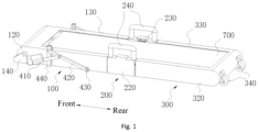
Fig. 1 is a schematic structural diagram of a running state of a foldable treadmill provided by some examples of the disclosure. -
Fig. 2 is a schematic structural diagram of a storage state of a foldable treadmill provided by some examples of the disclosure. -
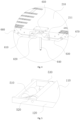
Fig. 3 is a schematic structural diagram of a linkage mechanism of a foldable treadmill provided by some examples of the disclosure. -
Fig. 4 is an enlarged diagram of a part A inFig. 3 . -
Fig. 5 is a structural diagram of a second drive mechanism of a foldable treadmill provided by some examples of the disclosure. -
Fig. 6 is a structural diagram of a second roller and a second rolling wheel of a foldable treadmill provided by some examples of the disclosure. - 100-front running plate assembly; 110-front running plate; 120-front fixed support; 130-front decorating plate; 140-fixed base; 200-middle running plate assembly; 210-middle running plate; 211-avoidance space; 220-middle fixed support; 230-middle decorating plate; 240-handle; 300-rear running plate assembly; 310-rear running plate; 320-rear fixed support; 330-rear decorating plate; 340-second rolling wheel; 410-linear drive unit; 420-stay bar; 430-first rolling wheel; 440-support frame; 510-drive motor; 520-drive belt; 530-first roller; 540-seocnd roller; 610-first connecting piece; 620-H-shaped connecting rod; 630-second connecting piece; 640-slide rail; 650-fixed plate; 660-first hinge; 670-second hinge; and 700-running belt.
- Examples will be illustrated in detail here, and their instances are represented in the accompanying drawings. Unless otherwise indicated, when the following description refers to the accompanying drawings, the same number in the different accompanying drawings represents the same or similar elements. Implementations described in the following examples do not represent all implementations consistent with the examples of the disclosure. Rather, they are merely examples of an apparatus and method consistent with some aspects of the disclosure as detailed in appended claims.
- In the disclosure, without a statement to the contrary, used positional words such as "up, down, left and right" usually refer to be defined based on a drawing direction of the corresponding accompanying drawing; "inner and outer" refer to an interior and an exterior of a profile of a corresponding component; "far and near" refer to a corresponding structure or a corresponding component away from or close to another structure or component; "front and rear" refer to a front and a rear of a human body when a treadmill is in a using state; "left and right" refer to a left side and a right side of the human body when the treadmill is in a using state; and "width" refers to a direction of two sides of the human body when the treadmill is in a using state. Moreover, it needs to be explained that used terms "first", "second" and the like are intended to distinguish one element from another element.
- As shown in
Fig. 1 to Fig. 6 , some examples of the disclosure provide a foldable treadmill. The foldable treadmill includes a frontrunning plate assembly 100, a middle runningplate assembly 200 and a rear runningplate assembly 300, where the frontrunning plate assembly 100 and the rear runningplate assembly 300 are hingedly connected to two ends of the middle runningplate assembly 200 in a front-back direction respectively; the foldable treadmill further includes: a first drive mechanism, connected to the frontrunning plate assembly 100 or the rear runningplate assembly 300; and a linkage mechanism, separately connected to the frontrunning plate assembly 100, the middle runningplate assembly 200, and the rear runningplate assembly 300, so that when the first drive mechanism drives the frontrunning plate assembly 100 or the rear runningplate assembly 300, the frontrunning plate assembly 100 and the rear runningplate assembly 300 can synchronously rotate relative to the middle runningplate assembly 200 to be switched between a folding position and an unfolding position. In the unfolding position, upper surfaces of the frontrunning plate assembly 100, the middle runningplate assembly 200, and the rear runningplate assembly 300 are coplanar, and in the folding position, the frontrunning plate assembly 100 and the rear runningplate assembly 300 get close to each other so as to lift the middle runningplate assembly 200 upwards. - Through the above technical solution, namely the foldable treadmill of the disclosure, the first drive mechanism is used for driving one end, close to the middle running
plate assembly 200, of one of the frontrunning plate assembly 100 and the rear runningplate assembly 300 to rotate upwards and be lifted relative to the other end, and the middle runningplate assembly 200 is folded with one of the frontrunning plate assembly 100 and the rear runningplate assembly 300; at the same time, the frontrunning plate assembly 100, the middle running plate assembly and the rear runningplate assembly 300 are connected through the linkage mechanism, such that when the middle runningplate assembly 200 is folded with one of the frontrunning plate assembly 100 and the rear runningplate assembly 300, the other one of the frontrunning plate assembly 100 and the rear runningplate assembly 300 is also synchronously folded with the middle runningplate assembly 200, and thus, the frontrunning plate assembly 100 and the rear runningplate assembly 300 get close to each other so as to lift the middle runningplate assembly 200 upwards to be folded; and similarly, when the first drive mechanism drives one of the frontrunning plate assembly 100 and the rear runningplate assembly 300 to be unfolded, the other one may also be synchronously unfolded. The foldable treadmill of the disclosure may be automatically folded in three sections, is small in height and thickness of the overall size, reduces the occupied space, and is convenient to store and carry. - It needs to be explained that the inventive concept of the disclosure may simultaneously further be expanded to a walking machine, a walking and running machine and other sport fitness equipment.
- In some examples of the disclosure, the first drive mechanism may be connected to the front
running plate assembly 100, for driving the frontrunning plate assembly 100 to rotate relative to the middle runningplate assembly 200 to fold the frontrunning plate assembly 100 and the middle runningplate assembly 200; and meanwhile, since the rear runningplate assembly 300 is hingedly connected to the middle runningplate assembly 200, in conjunction with the linkage mechanism, the rear runningplate assembly 300 and the middle runningplate assembly 200 may also be synchronously folded, such that the treadmill is automatically folded in three sections, and the space is optimally saved. - In some other examples of the disclosure, the first drive mechanism may also be connected to the rear running
plate assembly 300, for driving the rear runningplate assembly 300 to rotate relative to the middle runningplate assembly 200 to fold the rear runningplate assembly 300 and the middle runningplate assembly 200; and meanwhile, since the frontrunning plate assembly 100 is hingedly connected to the middle runningplate assembly 200, in conjunction with the linkage mechanism, the frontrunning plate assembly 100 and the middle runningplate assembly 200 may also be synchronously folded, such that the treadmill is automatically folded in three sections as well. - Optionally, in the folding position, an angle between the front
running plate assembly 100 and the middle runningplate assembly 200 and/or between the rear runningplate assembly 300 and the middle runningplate assembly 200 is 90°. That is, in some examples, when the frontrunning plate assembly 100 and the rear runningplate assembly 300 rotate by 90° towards a direction close to a bottom face of the middle runningplate assembly 200, the frontrunning plate assembly 100 and the rear runningplate assembly 300 are both at a position perpendicular to the middle runningplate assembly 200, and the foldable treadmill is folded. When the frontrunning plate assembly 100 and the rear runningplate assembly 300 rotate towards a direction away from the bottom face of the middle runningplate assembly 200 to when upper surfaces of the frontrunning plate assembly 100 and the rear runningplate assembly 300 are both coplanar with an upper surface of the middle runningplate assembly 200, namely, the frontrunning plate assembly 100, the middle runningplate assembly 200 and the rear runningplate assembly 300 are in a same horizontal plane, the foldable treadmill is unfolded. - The first drive mechanism may be constructed in any mode, as shown in
Fig. 1 andFig. 2 , in some examples of the disclosure, the first drive mechanism is constructed as alinear drive unit 410, astay bar 420 and afirst rolling wheel 430; and thelinear drive unit 410 includes but is not limited to an electric push rod, a linear module or a driving cylinder, and the driving cylinder may be a hydraulic cylinder, an air cylinder or an electric cylinder, etc. A fixed end of thelinear drive unit 410 is hingedly connected to the frontrunning plate assembly 100, one end of thestay bar 420 is hingedly connected to the frontrunning plate assembly 100, thefirst rolling wheel 430 is rotatably arranged at the other end of thestay bar 420 and abuts against the ground, and a drive end of thelinear drive unit 410 is hingedly connected to thestay bar 420. - One end of the
stay bar 420 is hingedly connected to an upper end of asupport frame 440 fixedly arranged on the frontrunning plate assembly 100, the other end of thestay bar 420 is connected to the rotatablefirst rolling wheel 430, and thefirst rolling wheel 430 makes contact with the ground, and can roll on the ground. When the first drive mechanism works, thestay bar 420 connected to thefirst rolling wheel 430 may reduce frictional force with the ground, which facilitates rotating of thestay bar 420. The fixed end of thelinear drive unit 410 is hingedly connected to a front end of the frontrunning plate assembly 100, a drive end of thelinear drive unit 410 is hingedly connected to thestay bar 420, and thestay bar 420 is driven by extending and retracting of thelinear drive unit 410 to rotate relative to a hinge position of thestay bar 420 and thesupport frame 440, such that thefirst rolling wheel 430 moves on the ground in a front-rear direction. When the treadmill needs to be folded, the first rolling wheel 430 is driven by the linear drive unit 410 to move to a direction of the front end of the front running plate assembly 100, one end of the front running plate assembly 100 close to the middle running plate assembly 200 rotates and is lifted upwards relative to the other end, that is, under the action of the stay bar 420, a rear end of the front running plate assembly 100 rotates upwards relative to the front end, such that the front running plate assembly 100 and the middle running plate assembly 200 are folded; meanwhile, by arranging the linkage mechanism, in this time, the rear running plate assembly 300 is driven by the middle running plate assembly 200 to move towards a direction close to the front running plate assembly 100, and the rear running plate assembly 300 rotates and is folded relative to the middle running plate assembly 200; and finally, when the front running plate assembly 100 is at a position perpendicular to the middle running plate assembly 200, the rear running plate assembly 300 is also at the position perpendicular to the middle running plate assembly 200, which is equivalent to that the front running plate assembly 100 and the rear running plate assembly 300 get close to each other to jack up the middle running plate assembly 200 upwards, such that the treadmill is folded, and the foldable treadmill may be stored as a cuboid shape, which reduces sizes in the front-rear direction and a height direction. - When the foldable treadmill needs to be unfolded, the
first rolling wheel 430 is driven by thelinear drive unit 410 to move to a direction of the rear end of the frontrunning plate assembly 100, one end of the frontrunning plate assembly 100 close to the middle runningplate assembly 200 rotates and is lowered downwards relative to the other end, that is, under the action of thestay bar 420, the rear end of the frontrunning plate assembly 100 rotates downwards relative to the front end, such that the frontrunning plate assembly 100 and the middle runningplate assembly 200 are unfolded; meanwhile, by arranging the linkage mechanism, in this time, the rear runningplate assembly 300 is driven by a middle running plate to move towards a direction away from the frontrunning plate assembly 100, and the rear runningplate assembly 300 rotates and is unfolded relative to the middle runningplate assembly 200; and finally, when the upper surface of the frontrunning plate assembly 100 and the upper surface of the middle runningplate assembly 200 are within the same horizontal plane, the upper surface of the rear runningplate assembly 300 and the upper surface of the middle runningplate assembly 200 are also within the same horizontal plane, and thus the treadmill is unfolded. - In some other examples of the disclosure, the first drive mechanism further includes a fixed
base 140, one end of the frontrunning plate assembly 100 away from the middle runningplate assembly 200 is rotatably connected to the fixedbase 140, and a fixed end of thelinear drive unit 410 is hingedly connected to the fixedbase 140. The fixedbase 140 makes contact with the ground, the front end of the frontrunning plate assembly 100 is hingedly connected to the fixedbase 140, such that the frontrunning plate assembly 100 is capable of rotating relative to the fixedbase 140, and the fixed end of thelinear drive unit 410 is hingedly connected to the fixedbase 140, so as to adapt to change of a position of thelinear drive unit 410 when thestay bar 420 rotates. - As shown in
Fig. 1 andFig. 6 , in some examples of the disclosure, the foldable treadmill further includes asecond rolling wheel 340 rotatably arranged at one end of the rear runningplate assembly 300 away from the middle runningplate assembly 200. In a process of folding and unfolding the treadmill, the treadmill may be conveniently stored and moved, when the foldable treadmill is not stored, since thesecond rolling wheel 340 is arranged at a rear end of the rear runningplate assembly 300, a front end of the foldable treadmill may be lifted, and the treadmill is moved depending on thesecond rolling wheel 340. The treadmill may be conveniently carried, moved, stored to lean against the wall, placed on the ground or hided under a bed, etc. through rotation of thesecond rolling wheel 340 after being folded and stored. - It may be understood that the plurality of second rolling
wheels 340 may be arranged at intervals in a width direction of the rear runningplate assembly 300, and when in use, a user can better grasp the balance. Optionally, twosecond rolling wheels 340 are arranged, and rotatably arranged at the rear end of the rear runningplate assembly 300 in a spaced mode. - In some implementations of the disclosure, two first drive mechanisms and two linkage mechanisms are arranged, and the two first drive mechanisms and the two linkage mechanisms are respectively and symmetrically arranged on two sides of the front
running plate assembly 100 and the middle runningplate assembly 200 in a left-right direction. The two first drive mechanisms are respectively arranged on two sides of a width direction of the frontrunning plate assembly 100, so as to more stably and reliably drive the frontrunning plate assembly 100 to rotate; and the two linkage mechanisms are respectively on two sides of a width direction of the middle runningplate assembly 200, so as to more smoothly drive the rear runningplate assembly 300 to be linked to the frontrunning plate assembly 100. - The front
running plate assembly 100 is rotatably connected to the middle runningplate assembly 200 through afirst hinge 660, and the rear runningplate assembly 300 is rotatably connected to the middle runningplate assembly 200 through asecond hinge 670. Thefirst hinge 660 and thesecond hinge 670 may be constructed in any mode in the related art as long as the above folding and unfolding may be achieved, which is not limited in the disclosure. In some examples, thefirst hinge 660 and thesecond hinge 670 in the disclosure may select a 90° internally-folded hinge, such that the frontrunning plate assembly 100 and the rear runningplate assembly 300 may both rotate by 90° relative to the middle runningplate assembly 200, namely, rotate to a position perpendicular to the middle runningplate assembly 200. - The linkage mechanism may be constructed in any mode, as shown in
Fig. 3 andFig. 4 , in some implementations of the disclosure, the linkage mechanism may be constructed as a first connectingpiece 610, a second connectingpiece 630, an H-shaped connectingrod 620 and aslide rail 640; the H-shaped connectingrod 620 is arranged below the middle runningplate assembly 200, a front end of the H-shaped connectingrod 620 is hingedly connected to one end of the first connectingpiece 610, the other end of the first connectingpiece 610 is hingedly connected to thefirst hinge 660, a rear end of the H-shaped connectingrod 620 is hingedly connected to one end of the second connectingpiece 630, and the other end of the second connectingpiece 630 is hingedly connected to thesecond hinge 670; and one end of theslide rail 640 is connected to the middle runningplate assembly 200 via a fixedplate 650, and extends downwardly with respect to the middle runningplate assembly 200, a sliding hole through which theslide rail 640 penetrates is formed in the H-shaped connectingrod 620, and theslide rail 640 is slidably inserted in the sliding hole. When the first drive mechanism drives the frontrunning plate assembly 100 to rotate and be lifted, the first connectingpiece 610 drives the H-shaped connectingrod 620 to move upwards along theslide rail 640, meanwhile, the H-shaped connectingrod 620 drives an end portion of the second connectingpiece 630 connected with the H-shaped connecting rod to move upwards similarly, one end of the second connectingpiece 630 connected to thesecond hinge 670 rotates and is folded relative to the middle runningplate assembly 200 while driving the rear runningplate assembly 300 to move towards a direction of the frontrunning plate assembly 100, and thus, the frontrunning plate assembly 100 and the rear runningplate assembly 300 are capable of synchronized action. When the H-shaped connectingrod 620 moves to an upper end of theslide rail 640, the frontrunning plate assembly 100 and the rear runningplate assembly 300 both rotate to the position perpendicular to the middle runningplate assembly 200, and the treadmill is folded. When the treadmill needs to be unfolded and the first drive mechanism drives the frontrunning plate assembly 100 to rotate and descend, the first connectingpiece 610 drives the H-shaped connectingrod 620 to move downwards along theslide rail 640, the H-shaped connectingrod 620 drives the second connectingpiece 630 to move reversely, one end connected to thesecond hinge 670 rotates and is unfolded relative to the middle runningplate assembly 200 while driving the rear runningplate assembly 300 to move towards a direction away from the frontrunning plate assembly 100, and the frontrunning plate assembly 100 and the rear runningplate assembly 300 are capable of synchronized action. When the H-shaped connectingrod 620 moves to a lower end of theslide rail 640, the upper surfaces of the frontrunning plate assembly 100 and the rear runningplate assembly 300 both rotate to the same horizontal plane with the upper surface of the middle runningplate assembly 200, and the treadmill is unfolded. - Considering that the arrangement of the
slide rail 640 will increase a thickness of the middle runningplate assembly 200 to a certain degree, which is not beneficial for lightness and thinness of the treadmill. Thus, in some other examples of the disclosure, anavoidance space 211 for moving of the H-shaped connectingrod 620 and theslide rail 640 is arranged at a bottom of the middle runningplate assembly 200. That is, a groove with a downward opening is formed in the bottom of the middle runningplate assembly 200, the H-shaped connectingrod 620 and theslide rail 640 are arranged in the groove, and the groove forms theabove avoidance space 211, such that the H-shaped connectingrod 620 and theslide rail 640 may further be mounted and arranged on the premise of the smaller thickness of the middle runningplate assembly 200. - In some examples of the disclosure, the foldable treadmill further includes
handles 240 arranged on the middle runningplate assembly 200. After the foldable treadmill is folded, a user may apply a force through thehandles 240, the user may conveniently carry or move the folded treadmill to other positions, and the use experience of the user is improved. - As shown in
Fig. 5 , in some examples, the foldable treadmill further includes a runningbelt 700 and a second drive mechanism. The second drive mechanism includes adrive motor 510, adrive belt 520, afirst roller 530 and asecond roller 540; thefirst roller 530 is rotatably arranged on the frontrunning plate assembly 100, thesecond roller 540 is rotatably arranged on the rear runningplate assembly 300, and the runningbelt 700 surrounds thefirst roller 530 and thesecond roller 540; and thedrive belt 520 respectively sleeves thefirst roller 530 and a drive shaft of thedrive motor 510. The runningbelt 700 respectively sleeves thefirst roller 530 and thesecond roller 540, thefirst roller 530 is rotatably arranged on the frontrunning plate assembly 100, thesecond roller 540 is rotatably arranged on the rear runningplate assembly 300, and thedrive motor 510 drives thefirst roller 530 to rotate through thedrive belt 520, such that the runningbelt 700 is driven to rotate around thefirst roller 530 and thesecond roller 540. - The front running plate assembly, the middle running plate assembly and the rear running plate assembly may be constructed in any mode. In some examples, the front
running plate assembly 100 may include afront running plate 110, a front fixedsupport 120 and afront decorating plate 130. Thefront running plate 110 is fixedly arranged on the frontfixed support 120, and thefront decorating plate 130 is arranged on the frontfixed support 120 in a covering mode. The frontfixed support 120 is rotatably connected to the above fixedbase 140, and meanwhile, thefront decorating plate 130 may further shield thedrive motor 510, thedrive belt 520 and thefirst roller 530 of the second drive mechanism so as to improve an artistic effect of the foldable treadmill. - In some other examples, the rear running
plate assembly 300 may also include arear running plate 310, a rear fixedsupport 320 and arear decorating plate 330. Therear running plate 310 is fixedly arranged on the rear fixedsupport 320. therear decorating plate 330 is arranged on the rear fixedsupport 320 in a covering mode, and similarly, therear decorating plate 330 may further shield the abovesecond roller 540 so as to improve the aesthetics. - In some other examples, the middle running
plate assembly 200 includes amiddle running plate 210, a middlefixed support 220 and amiddle decorating plate 230. Themiddle running plate 210 is fixedly arranged on the middlefixed support 220, and themiddle decorating plate 230 is arranged on the middlefixed support 220 in a covering mode. Thehandles 240 may be fixedly connected to the middlefixed support 220 or themiddle decorating plate 230, twohandles 240 may be arranged, and the twohandles 240 are symmetrically arranged with respect to a central axis of a width direction of themiddle running plate 210. - According to the foldable treadmill provided by the example of the disclosure, the front
running plate assembly 100 and the rear runningplate assembly 300 are both connected to the middle runningplate assembly 200 by adopting the 90° internally-folded hinge, and the three running plate assemblies may be folded to be a U shape by internally rotating 90 degrees. The frontrunning plate assembly 100 is rotatably connected to the middle runningplate assembly 200 through thefirst hinge 660, and the rear runningplate assembly 300 is rotatably connected to the middle runningplate assembly 200 through thesecond hinge 670. The linkage mechanism includes the first connectingpiece 610, the second connectingpiece 630, the H-shaped connectingrod 620 and theslide rail 640; and two ends of the H-shaped connectingrod 620 are respectively connected to the frontrunning plate assembly 100 and the rear runningplate assembly 300 through the first connectingpiece 610 and the second connectingpiece 630, the sliding hole is formed in the H-shaped connectingrod 620, theslide rail 640 is slidably inserted in the sliding hole, and the upper end of theslide rail 640 is fixedly connected to the middle runningplate assembly 200 through a fixedplate 650. The H-shaped connectingrod 620 can slide up and down along theslide rail 640 to ensure that the frontrunning board assembly 100 and the rear runningboard assembly 300 can synchronize their movements. The first drive mechanism includes thelinear drive unit 410, thestay bar 420 and thefirst rolling wheel 430. A bottom face of the fixedbase 140 makes contact with the ground, and a relative position of the fixed base is kept unchanged through the frictional force with the ground. The front end of the frontrunning plate assembly 100 may be rotatably connected to an inner side of the fixedbase 140, thelinear drive unit 410 may select an electric push rod, one end of the electric push rod may be rotatably connected to an outer side of the fixedbase 140, the other end of the electric push rod is hingedly connected to thestay bar 420, one end of thestay bar 420 is hingedly connected to thesupport frame 440, thesupport frame 440 is fixed to thefront decorating plate 130 of the frontrunning plate assembly 100, the other end of thestay bar 420 is connected to thefirst rolling wheel 430 capable of freely rotating, and thus, the electric push rod drives thestay bar 420 to move when retracts so as to achieve a folding and storage process of the treadmill. Thedrive motor 510, thedrive belt 520 and thefirst roller 530 are fixed to the frontrunning plate assembly 100, which matches with thesecond roller 540 of the rear runningplate assembly 300 to achieve moving of the runningbelt 700. The rear end of the rear runningplate assembly 300 is rotatably connected to a pair of second rollingwheels 340, in the automatic folding process, the front end of the frontrunning plate assembly 100 is hingedly connected to the fixedbase 140, the fixedbase 140 does not move relative to the ground due to the frictional force, and when the frontrunning plate assembly 100 rotates, the rear runningplate assembly 300 gradually gets close to the frontrunning plate assembly 100 under driving of the linkage mechanism to be folded. A pair ofhandles 240 are fixedly arranged on themiddle decorating plate 230 of the middle runningplate assembly 200, after being stored, thefirst rolling wheel 430 of thestay bar 420 is located at the bottom of the folded treadmill, and the treadmill may be conveniently carried and moved. When being not stored, the second rollingwheels 340 are similarly arranged at a rear end of the foldable treadmill, such that people may lift the front end of the treadmill when the treadmill is not stored so as to move the treadmill depending on the second rollingwheels 340. The foldable treadmill may be automatically folded in three sections, a dirty surface making contact with the ground cannot be exposed, the foldable treadmill is finally stored in a cuboid shape, thefirst rolling wheel 430 and the second rollingwheels 340 are arranged at the bottom, and the user may conveniently carry the foldable treadmill, move it, store it to lean against the wall, place it on the ground, or hide it under the bed. - After considering the specification and practicing the disclosure, those skilled in the art may easily think of other implementation solutions of the disclosure. The present application is intended to contain any variation, application or adaptive change of the disclosure, and these variations, applications or adaptive changes follow general principles of the disclosure and include commonly-known knowledge or conventional technical means in the technical field not disclosed in the disclosure. The specification and examples are merely regarded as illustrative, the true scope and spirit of the disclosure are indicated by the claims below.
- It needs to be understood that the disclosure is not limited to an accurate structure described above and shown in the accompanying drawings, and various modifications and changes can be made without departing away from the scope of the disclosure. The scope of the disclosure is merely limited by the appended claims.
- Preferred implementations of the disclosure are described in detail above in conjunction with the accompanying drawings, however, the disclosure is not limited to specific details in the above implementation, within the technical conception scope of the disclosure, various simple variations can be made to the technical solution of the disclosure, and all these simple variations belong to the scope of protection of the disclosure.
- In addition, it needs to be noted that various specific technical features described in the above specific implementation may be combined in any appropriate mode without conflict, and in order to avoid needless repetitions, the disclosure does not explain various possible combination modes.
- In addition, the various different implementations of the disclosure may also be combined arbitrarily, as long as they do not contradict the idea of the disclosure, and they also are to be regarded as contents disclosed in the disclosure.
Claims (12)
- A foldable treadmill, is characterized in that the foldable treadmill comprises a front running plate assembly (100), a middle running plate assembly (200) and a rear running plate assembly (300), the front running plate assembly (100) and the rear running plate assembly (300) are hingedly connected to two ends of the middle running plate assembly (200) in a front-back direction respectively;
the foldable treadmill further comprises:a first drive mechanism, connected to the front running plate assembly (100) or the rear running plate assembly (300); anda linkage mechanism, separately connected to the front running plate assembly (100), the middle running plate assembly (200), and the rear running plate assembly (300), so that when the first drive mechanism drives the front running plate assembly (100) or the rear running plate assembly (300), the front running plate assembly (100) and the rear running plate assembly (300) can synchronously rotate relative to the middle running plate assembly (200) to be switched between a folding position and an unfolding position; andin the unfolding position, upper surfaces of the front running plate assembly (100), the middle running plate assembly (200), and the rear running plate assembly (300) are coplanar, and in the folding position, the front running plate assembly (100) and the rear running plate assembly (300) get close to each other to lift the middle running plate assembly (200) upwards. - The foldable treadmill according to claim 1, characterized in that in the folding position, an angle between the front running plate assembly (100) and the middle running plate assembly (200) and/or between the rear running plate assembly (300) and the middle running plate assembly (200) is 90°.
- The foldable treadmill according to claim 1, characterized in that the first drive mechanism is constructed as a linear drive unit (410), a stay bar (420) and a first rolling wheel (430); and
a fixed end of the linear drive unit (410) is hingedly connected to the front running plate assembly (100), one end of the stay bar (420) is hingedly connected to the front running plate assembly (100), the first rolling wheel (430) is rotatably arranged at the other end of the stay bar (420) and abuts against the ground, and a drive end of the linear drive unit (410) is hingedly connected to the stay bar (420). - The foldable treadmill according to claim 3, characterized in that the first drive mechanism further comprises a fixed base (140), one end of the front running plate assembly (100) away from the middle running plate assembly (200) is rotatably connected to the fixed base (140), and the fixed end of the linear drive unit (410) is hingedly connected to the fixed base (140).
- The foldable treadmill according to claim 3, characterized in that the linear drive unit (410) comprises an electric push rod, a linear module or a driving cylinder.
- The foldable treadmill according to claim 3, characterized in that the foldable treadmill further comprises a second rolling wheel (340) being rotatably arranged at one end of the rear running plate assembly (300) away from the middle running plate assembly (200).
- The foldable treadmill according to claim 1, characterized in that two first drive mechanisms and two linkage mechanisms are arranged, and the two first drive mechanisms and the two linkage mechanisms are respectively and symmetrically arranged on two sides of the front running plate assembly (100) and the middle running plate assembly (200) in a left-right direction.
- The foldable treadmill according to claim 1, characterized in that the front running plate assembly (100) is rotatably connected with the middle running plate assembly (200) through a first hinge (660), and the rear running plate assembly (300) is rotatably connected with the middle running plate assembly (200) through a second hinge (670);the linkage mechanism is constructed as a first connecting piece (610), a second connecting piece (630), an H-shaped connecting rod (620) and a slide rail (640);the H-shaped connecting rod (620) is arranged below the middle running plate assembly (200), a front end of the H-shaped connecting rod (620) is hingedly connected to one end of the first connecting piece (610), the other end of the first connecting piece (610) is hingedly connected to the first hinge (660), a rear end of the H-shaped connecting rod (620) is hingedly connected to one end of the second connecting piece (630), and the other end of the second connecting piece (630) is hingedly connected to the second hinge (670); andone end of the slide rail (640) is connected to the middle running plate assembly (200) and extends downwards, a sliding hole through which the slide rail (640) penetrates is formed in the H-shaped connecting rod (620), and the slide rail (640) is slidably inserted in the sliding hole.
- The foldable treadmill according to claim 8, characterized in that an avoidance space (211) for moving of the H-shaped connecting rod (620) and the slide rail (640) is arranged at a bottom of the middle running plate assembly (200).
- The foldable treadmill according to any one of claims 1 to 9, characterized in that the foldable treadmill further comprises handles (240) arranged on the middle running plate assembly (200).
- The foldable treadmill according to any one of claims 1 to 9, characterized in that the foldable treadmill further comprises:a running belt (700); anda second drive mechanism; comprising a drive motor (510), a drive belt (520), a first roller (530) and a second roller (540); the first roller (530) being rotatably arranged on the front running plate assembly (100), the second roller (540) being rotatably arranged on the rear running plate assembly (300), and the running belt (700) surrounding the first roller (530) and the second roller (540); and the drive belt (520) respectively sleeving the first roller (530) and a drive shaft of the drive motor (510).
- The foldable treadmill according to any one of claims 1 to 9, characterized in that the front running plate assembly (100) comprises a front running plate (110), a front fixed support (120) and a front decorating plate (130);the front running plate (110) is fixedly arranged on the front fixed support (120), and the front decorating plate (130) is arranged on the front fixed support (120) in a covering mode; and/or, the rear running plate assembly (300) comprises a rear running plate (310), a rear fixed support (320) and a rear decorating plate (330);the rear running plate (310) is fixedly arranged on the rear fixed support (320), and the rear decorating plate (330) is arranged on the rear fixed support (320) in a covering mode; and/or, the middle running plate assembly (200) comprises a middle running plate (210), a middle fixed support (220) and a middle decorating plate (230); andthe middle running plate (210) is fixedly arranged on the middle fixed support (220), and the middle decorating plate (230) is arranged on the middle fixed support (220) in a covering mode.
Applications Claiming Priority (2)
| Application Number | Priority Date | Filing Date | Title |
|---|---|---|---|
| CN202123300376.9U CN216456717U (en) | 2021-12-23 | 2021-12-23 | Folding running machine |
| PCT/CN2022/089111 WO2023115771A1 (en) | 2021-12-23 | 2022-04-25 | Foldable treadmill |
Publications (2)
| Publication Number | Publication Date |
|---|---|
| EP4427820A1 true EP4427820A1 (en) | 2024-09-11 |
| EP4427820A4 EP4427820A4 (en) | 2025-11-12 |
Family
ID=81427356
Family Applications (1)
| Application Number | Title | Priority Date | Filing Date |
|---|---|---|---|
| EP22909108.7A Pending EP4427820A4 (en) | 2021-12-23 | 2022-04-25 | FOLDABLE TREADMILL |
Country Status (3)
| Country | Link |
|---|---|
| EP (1) | EP4427820A4 (en) |
| CN (1) | CN216456717U (en) |
| WO (1) | WO2023115771A1 (en) |
Family Cites Families (8)
| Publication number | Priority date | Publication date | Assignee | Title |
|---|---|---|---|---|
| US4300761A (en) * | 1980-10-06 | 1981-11-17 | Howard William E | Spring type exercising device |
| US20060003869A1 (en) * | 2004-07-02 | 2006-01-05 | Johnson Tech. Co., Ltd. | Folding treadmill |
| US20080280734A1 (en) * | 2007-05-09 | 2008-11-13 | Spark Innovations, Inc. | Folding treadmill |
| CN210992787U (en) * | 2019-09-09 | 2020-07-14 | 厦门奇品工业设计有限公司 | Treadmill with foldable base |
| CN211434920U (en) * | 2019-09-25 | 2020-09-08 | 北京金史密斯科技有限公司 | Walking machine |
| CN211434919U (en) * | 2019-09-25 | 2020-09-08 | 北京金史密斯科技有限公司 | Running machine |
| CN215231895U (en) * | 2021-07-16 | 2021-12-21 | 北京小米移动软件有限公司 | Folding running machine |
| CN113384847B (en) * | 2021-07-16 | 2024-11-12 | 北京小米移动软件有限公司 | Folding treadmill |
-
2021
- 2021-12-23 CN CN202123300376.9U patent/CN216456717U/en active Active
-
2022
- 2022-04-25 WO PCT/CN2022/089111 patent/WO2023115771A1/en not_active Ceased
- 2022-04-25 EP EP22909108.7A patent/EP4427820A4/en active Pending
Also Published As
| Publication number | Publication date |
|---|---|
| EP4427820A4 (en) | 2025-11-12 |
| WO2023115771A1 (en) | 2023-06-29 |
| CN216456717U (en) | 2022-05-10 |
Similar Documents
| Publication | Publication Date | Title |
|---|---|---|
| US11457728B2 (en) | Foldable table bench | |
| DE69827838T2 (en) | Foldable treadmill | |
| KR101813526B1 (en) | Motion simulator | |
| KR101676447B1 (en) | Apparatus for both table and digital information display | |
| CN107477317A (en) | A kind of display screen support frame of adjustable-angle | |
| KR20210148577A (en) | Roof top tent for vehicle | |
| CN216456717U (en) | Folding running machine | |
| CN100574833C (en) | Treadmill capable of being in flat folding form | |
| CN104720230A (en) | Inflatable opening assisting umbrella | |
| CN214678292U (en) | A picture and text show stores pylon for nursing teaching | |
| KR102803140B1 (en) | foldable massage mat | |
| KR20140139202A (en) | Treadmill | |
| CN213720593U (en) | Drawing auxiliary device for art design | |
| CN111388013A (en) | Portable ultrasonic machine | |
| JP3133321U (en) | Folding running machine | |
| CN216811516U (en) | Unit foldable invisible protective net | |
| CN207583209U (en) | Centering type hinge and collapsible door and window | |
| CN220608983U (en) | Telescopic running cabin | |
| US12426717B2 (en) | Foldable bed | |
| CN224071074U (en) | Manual adjustment lifting mechanism and running machine | |
| CN114012252B (en) | Laser marking device for radio frequency beauty instrument shell | |
| CN214624082U (en) | A board of preparing lessons for psychology teaching | |
| CN219752665U (en) | Seam splicing machine for processing backrest sleeves of automobile seats | |
| CN107930012B (en) | Physical education equipment | |
| CN214913062U (en) | Electric lifting structure of elliptical machine |
Legal Events
| Date | Code | Title | Description |
|---|---|---|---|
| STAA | Information on the status of an ep patent application or granted ep patent |
Free format text: STATUS: THE INTERNATIONAL PUBLICATION HAS BEEN MADE |
|
| PUAI | Public reference made under article 153(3) epc to a published international application that has entered the european phase |
Free format text: ORIGINAL CODE: 0009012 |
|
| STAA | Information on the status of an ep patent application or granted ep patent |
Free format text: STATUS: REQUEST FOR EXAMINATION WAS MADE |
|
| 17P | Request for examination filed |
Effective date: 20240604 |
|
| AK | Designated contracting states |
Kind code of ref document: A1 Designated state(s): AL AT BE BG CH CY CZ DE DK EE ES FI FR GB GR HR HU IE IS IT LI LT LU LV MC MK MT NL NO PL PT RO RS SE SI SK SM TR |
|
| DAV | Request for validation of the european patent (deleted) | ||
| DAX | Request for extension of the european patent (deleted) | ||
| A4 | Supplementary search report drawn up and despatched |
Effective date: 20251013 |
|
| RIC1 | Information provided on ipc code assigned before grant |
Ipc: A63B 22/02 20060101AFI20251007BHEP Ipc: A63B 22/00 20060101ALN20251007BHEP |
|
| STAA | Information on the status of an ep patent application or granted ep patent |
Free format text: STATUS: EXAMINATION IS IN PROGRESS |
|
| 17Q | First examination report despatched |
Effective date: 20260702 |