EP4426258B1 - Compounding system - Google Patents
Compounding system Download PDFInfo
- Publication number
- EP4426258B1 EP4426258B1 EP22801241.5A EP22801241A EP4426258B1 EP 4426258 B1 EP4426258 B1 EP 4426258B1 EP 22801241 A EP22801241 A EP 22801241A EP 4426258 B1 EP4426258 B1 EP 4426258B1
- Authority
- EP
- European Patent Office
- Prior art keywords
- luer
- luer coupling
- coupling
- container
- coupling end
- Prior art date
- Legal status (The legal status is an assumption and is not a legal conclusion. Google has not performed a legal analysis and makes no representation as to the accuracy of the status listed.)
- Active
Links
Images

Classifications
-
- A—HUMAN NECESSITIES
- A61—MEDICAL OR VETERINARY SCIENCE; HYGIENE
- A61J—CONTAINERS SPECIALLY ADAPTED FOR MEDICAL OR PHARMACEUTICAL PURPOSES; DEVICES OR METHODS SPECIALLY ADAPTED FOR BRINGING PHARMACEUTICAL PRODUCTS INTO PARTICULAR PHYSICAL OR ADMINISTERING FORMS; DEVICES FOR ADMINISTERING FOOD OR MEDICINES ORALLY; BABY COMFORTERS; DEVICES FOR RECEIVING SPITTLE
- A61J1/00—Containers specially adapted for medical or pharmaceutical purposes
- A61J1/14—Details; Accessories therefor
- A61J1/20—Arrangements for transferring or mixing fluids, e.g. from vial to syringe
- A61J1/2096—Combination of a vial and a syringe for transferring or mixing their contents
-
- A—HUMAN NECESSITIES
- A61—MEDICAL OR VETERINARY SCIENCE; HYGIENE
- A61J—CONTAINERS SPECIALLY ADAPTED FOR MEDICAL OR PHARMACEUTICAL PURPOSES; DEVICES OR METHODS SPECIALLY ADAPTED FOR BRINGING PHARMACEUTICAL PRODUCTS INTO PARTICULAR PHYSICAL OR ADMINISTERING FORMS; DEVICES FOR ADMINISTERING FOOD OR MEDICINES ORALLY; BABY COMFORTERS; DEVICES FOR RECEIVING SPITTLE
- A61J3/00—Devices or methods specially adapted for bringing pharmaceutical products into particular physical or administering forms
- A61J3/002—Compounding apparatus specially for enteral or parenteral nutritive solutions
-
- B—PERFORMING OPERATIONS; TRANSPORTING
- B65—CONVEYING; PACKING; STORING; HANDLING THIN OR FILAMENTARY MATERIAL
- B65B—MACHINES, APPARATUS OR DEVICES FOR, OR METHODS OF, PACKAGING ARTICLES OR MATERIALS; UNPACKING
- B65B3/00—Packaging plastic material, semiliquids, liquids or mixed solids and liquids, in individual containers or receptacles, e.g. bags, sacks, boxes, cartons, cans, or jars
- B65B3/003—Filling medical containers such as ampoules, vials, syringes or the like
Definitions
- the invention relates to a compounding system.
- the invention more specifically relates to establishing a Luer coupling between the container and the compounding system.
- the invention further relates to a method for establishing a Luer coupling between the container and the compounding system.
- the invention further relates to a computer program product for the method or controller in the compounding system.
- Pharmacies especially hospital pharmacies, have to compound medicines. These medicines may be compounded in the form of pills, but also in the form of syringes or infusion bags filled with a compounded substance. This compounding may be automated by coupling a syringe or infusion bag to a compounding system.
- US2017008651A1 discloses a machine and a method for the automatic preparation of substances for intravenous application.
- the machine works by puncturing a container with the needle of a syringe for thereafter drawing a liquid from the container in the syringe.
- US2017008651A1 further discloses in figure 8 a machine for establishing a Luer lock. Disadvantages of US2017008651A1 are that the machine is bulky, and mechanically complex. Furthermore, securely and reliably while also repeatably and automatically establishing a Luer coupling with the current soft plastics is difficult.
- WO 2007/130809 A2 discloses an automatic injectable drug mixing device including a syringe driver configured to receive a syringe in a predetermined syringe orientation and to operate the syringe in a predetermined series of linear movements, at least one needle configured to be coupled to the syringe during only part of a mixing operation including the predetermined series of linear movements, at least one vial containing a substance to be employed in mixing the drug and a precise positioner for maintaining the at least one vial and the at least one needle, when it is not coupled to the syringe, in precise mutual orientation with respect to each other and with respect to the syringe during at least part of the mixing operation.
- Disadvantages of WO 2007/130809 A2 are that the machine is unreliable, and mechanically complex. Furthermore, securely, and reliably while also repeatably and automatically establishing a Luer coupling with the current soft plastics is difficult.
- WO 2011/058560 A1 discloses a syringe connection module for connecting a syringe (10) to a syringe port of a fluid transfer device mounted on a medicinal vial and hereinafter referred to as a vial assemblage for liquid drug reconstitution and administration purposes.
- the syringe connection module includes a housing having a longitudinal housing axis, and a vial assemblage retaining arrangement for fixedly retaining the vial assemblage with its syringe port co- directional with the housing axis.
- the syringe connection module also includes a motorized syringe drive unit for supporting a syringe co- directional with the housing axis and its syringe connector co -axial with the syringe port and effecting a simultaneous combined rotation and linear displacement of the syringe towards the vial assemblage for connecting the syringe connector to the syringe port.
- a motorized syringe drive unit for supporting a syringe co- directional with the housing axis and its syringe connector co -axial with the syringe port and effecting a simultaneous combined rotation and linear displacement of the syringe towards the vial assemblage for connecting the syringe connector to the syringe port.
- An object of the invention is to overcome one or more of the disadvantages mentioned above.
- the invention is defined by the apended claims.
- a compounding system for dosing a compound in a container comprising a first Luer coupling end defining a first coupling axis, and comprising a first thread having a first screw thread end, and a first pitch; wherein the compounding system comprises: a Luer coupling holder for holding a second Luer coupling end defining a second coupling axis , and comprising a second screw thread having a second thread end, and a second pitch, wherein the first Luer coupling end and the second Luer coupling end are shaped to couple for forming a Luer coupling, and wherein the first thread and the second thread engage for establishing the Luer coupling; a container holder for holding the container, wherein the Luer coupling holder and the container holder are arranged for aligning the first coupling axis and the second coupling axis; a rotation actuator for rotating the container holder relative to the Luer coupling holder substantially around the first coupling axis;
- a compounding system is a system arranged for compounding substances, such as liquids or gels.
- the compounded substance is typically collected in a container.
- the container collects the different substances making up the compounded substance.
- the container is typically used for transporting and/or temporarily storing the compounded substance.
- the compounded substance in the container may be administered to a patient.
- the compounding system is typically used in medical settings, such as in a hospital pharmacy, for compounding syringes and/or infusion bags.
- the compounding system advantageously may alleviate manual labour.
- the compounding system may replace manual operation preventing failures. Both these advantages may also apply to the automated coupling and decoupling of the container.
- the container is typically a syringe and/or infusion bag. Syringes and infusion bags are standardized in the medical sector.
- the container has a container body typically provided with an inner space or a volume for holding or containing the compounded substance.
- the container body may have an elongated shape defining an elongated axis. The elongated axis may be aligned with the first coupling axis.
- a container such as a syringe or infusion bag, may be fitted with a Luer coupling end standardizing the coupling with the syringe or infusion bag.
- the compounding system holds a Luer coupling end shaped to cooperate or couple to the Luer coupling end of the container for forming a Luer coupling.
- the Luer coupling between the first Luer coupling end and the second Luer coupling end is established in several steps.
- the first step is to align the first coupling axis of the first Luer coupling end and the second coupling axis of the second Luer coupling end while both coupling ends are facing each other.
- the first Luer coupling end and/or the second Luer coupling end are translated along the aligned coupling axes in a direction towards each other.
- the first Luer coupling end and the second Luer coupling end contact each other, the translation is combined with a rotation, typically a right-hand rotation, of the first Luer coupling end relative to the second Luer coupling end around the aligned coupling axes.
- the rate of translation relative to the rate of rotation is based on the thread, more specific the thread pitch, of the Luer coupling ends.
- the translation and the rotation may both stop when either the first Luer coupling end reaches the end of the thread of the second Luer coupling end or vice versa, either Luer coupling end reaches an abutment in the other Luer coupling end.
- the translation and the rotation may be stopped after a particular distance or rotation is made or a set maximum driving torque is met. When the translation and the rotation are stopped, the Luer coupling is typically established.
- the compounding system may comprise a frame.
- the rotation actuator has a rotation axis typically identical, substantially identical, aligned or substantially aligned to the first coupling axis.
- the rotation actuator rotates the container holder relative to the Luer coupling holder around the rotation axis.
- either the container holder or the Luer coupling holder are stationary in the frame, while the other is rotatable by the rotation actuator.
- the translation actuator translates the container holder relative to the Luer coupling holder along the rotation axis.
- either the container holder or the Luer coupling holder are stationary in the frame, while the other is translatable by the translation actuator.
- the combination of rotating around and translating along the rotation axis allows the compounding system to support the automated establishing of the Luer coupling and/or Luer connection.
- the bias means bias the first Luer coupling end and the second Luer coupling end when in contact in a direction of the first coupling axis and/or rotation axis.
- the bias means typically indent or deform with an increasing or rising bias. At the first moment the first Luer coupling end and the second Luer coupling end contact, the bias is zero, substantially zero or neglectable.
- the bias means absorb this translation or displacement. Typically, the bias increases with this translation or displacement.
- the engagement requires a specific rotation and a specific translation at the same time.
- the specific rotation and the specific translation may vary over production batches, manufacturer and/or Luer coupling types.
- the bias means allow for a mismatch between the rotation and translation of the first Luer coupling end relative to the second Luer coupling end. In case of a mismatch, the bias means absorb this mismatch typically increasing or decreasing the bias.
- the current system allows for decoupling or loosely coupling the rotation and translation of the first Luer coupling end and the second Luer coupling end. This decoupling or loosely coupling provides the advantage of simplifying the control over the rotation actuator and/or the translation actuator.
- This decoupling or loosely coupling provides the advantage that the system may cope with variations over production batches, manufacturer and/or Luer coupling types.
- the bias may even be arranged such that the translation actuator is not activated during that the rotation actuator is activated for establishing the Luer coupling, thereby providing the advantage of fully decoupling the control over or powering of the rotation actuator relative to the translation actuator.
- the position sensor senses the position of the container holder relative to the Luer coupling holder.
- the distance between the container holder and the first Luer coupling end along or in the direction of the first coupling axis is known, predefined or settable.
- the distance between the Luer coupling holder and the second Luer coupling end along or in the direction of the second coupling axis is known, predefined or settable. Therefore, typically the controller with the additional distance information may deduce or estimate the distance between the Luer coupling ends. And if the Luer coupling ends are in contact with each other, the controller may derive the amount of depression of the bias means. With additional parameters of the bias means, the controller may even deduce or estimate the amount of bias exerted on the Luer coupling ends.
- the controller may maintain or keep the exerted bias below a specific maximum bias threshold preventing deforming or even damage on the Luer coupling ends.
- the controller may determine or calculate if the depression is enough for providing the translation along the first coupling axis for establishing the Luer coupling, such as without activating the translation actuator.
- the two thread ends When the first Luer coupling end and the second Luer coupling end are in contact, biased, and rotated in a non-engaging rotational direction, the two thread ends will contact each other. Typically, as long as the thread ends did not pass each other, the Luer coupling ends will separate from each other, move away from each other, or separate from each other along the first Luer coupling axis. The rate of separation may be determined depending on the pitch of the threads of the Luer coupling ends and the amount of rotation of the Luer coupling ends relative to each other. As soon as the thread ends pass each other, due to the bias, the thread ends will jump or suddenly change in a translational direction, such as along the first coupling axis. The jump or sudden change is typically substantially equal to the pitch of the thread ends. Typically, due to the sudden jump, the Luer coupling ends move towards each other.
- the respective Luer coupling ends are typically of soft plastic. These soft plastics typically have no hard enough abutment causing the engaging Luer coupling ends to jump over or skip the abutment.
- the current invention allows to detect the position, specifically the angular position, of the respective thread end relative to each other. Thereafter the thread ends may engage using the knowledge of the relative position. The thread ends may thereafter advantageously engage without the Luer coupling ends, specifically the thread ends, jumping over or skipping each other's respective abutments. Furthermore, the threads may hereafter advantageously engage such that the Luer coupling ends couple without leaking fluids passing through the Luer coupling ends.
- a method for controlling a compounding system for dosing a compound in a container comprising a first Luer coupling end defining a first coupling axis, and comprising a first thread having a first screw thread end, and a first pitch; wherein the compounding system comprises: a Luer coupling holder for holding a second Luer coupling end defining a second coupling axis, wherein the first Luer coupling end and the second Luer coupling end are shaped to couple for forming a Luer coupling, and comprising a second screw thread having a second thread end, and a second pitch; a container holder for holding the container, wherein the Luer coupling holder and the container holder are arranged for aligning the first coupling axis and the second coupling axis; a rotation actuator for rotating the container holder relative to the Luer coupling holder substantially around the first coupling axis; a translation actuator for translating the container holder relative to the Luer coupling holder
- a computer program product comprising a computer readable medium having computer readable code embodied therein, the computer readable code being configured such that, on execution on the compounding system, the compounding system is caused to perform any of the methods mentioned, or configuration of the controller of one of the compounding systems mentioned.
- a compounding system for dosing a compound in a container comprising a first Luer coupling end defining a first coupling axis; wherein the compounding system comprises: a Luer coupling holder for holding a second Luer coupling end defining a second coupling axis (As), wherein the first Luer coupling end and the second Luer coupling end are shaped to couple for forming a Luer coupling; a container holder for holding the container, wherein the Luer coupling holder and the container holder are arranged for aligning the first coupling axis and the second coupling axis; a rotation actuator for rotating the container holder relative to the Luer coupling holder substantially around the first coupling axis; a translation actuator for translating the container holder relative to the Luer coupling holder along the first coupling axis; bias means arranged for biasing the first Luer coupling end and the second Luer coupling end when in contact in a direction of the first coupling axis; and
- Also disclosed is a method for controlling a compounding system for dosing a compound in a container comprising a first Luer coupling end defining a first coupling axis; wherein the compounding system comprises: a Luer coupling holder for holding a second Luer coupling end defining a second coupling axis, wherein the first Luer coupling end and the second Luer coupling end are shaped to couple for forming a Luer coupling; a container holder for holding the container, wherein the Luer coupling holder and the container holder are arranged for aligning the first coupling axis and the second coupling axis; a rotation actuator for rotating the container holder relative to the Luer coupling holder substantially around the first coupling axis; a translation actuator for translating the container holder relative to the Luer coupling holder along the first coupling axis; and bias means arranged for biasing the first Luer coupling end and the second Luer coupling end when in contact in a direction of the first coupling axi
- the controller is configured for: activating the translation actuator such that the two Luer coupling ends contact and the bias means are biased; and after biasing, activating the rotation actuator for engaging the two Luer coupling ends, wherein the bias is sufficient for providing the translation of the container along the first coupling axis.
- the rotation actuator may be operated independent from the translation actuator thereby simplifying the control of the controller.
- the rotation actuator may remain stationary, uncontrolled, or unpowered while the translation actuator is activated or moving the first Luer coupling end, such as the container, relative to the second Luer coupling end along the first coupling axis.
- the translation actuator may remain stationary, uncontrolled, or unpowered while the rotation actuator is activated or rotating the first Luer coupling end, such as the container, relative to the second Luer coupling end around the first coupling axis.
- the bias is sufficient for providing a translation of the first Luer coupling end relative to the second Luer coupling end along the first coupling axis during the activation of at least 0.50, preferably 0.75, more preferably 1.0, more preferably 1.25, more preferably 1.5, more preferably 2.0, most preferably 2.5 of the first pitch and/or the second pitch.
- the Luer coupling ends when contacting and typically also biased may typically after rotating a specific or predefined number of radials in an engaging direction establish the Luer coupling.
- the Luer coupling during rotating in an engaging or establishing manner will induce a translation of the first Luer coupling end relative to the second Luer coupling end toward each other along the first coupling axis.
- the bias means may be arranged for providing the specified translation preferably taking into account that the bias means may be used during engaging and during searching for the relative rotational position of the first Luer coupling end and the second Luer coupling end, more specifically respectively the first thread end and the second thread end.
- the bias means provide translation room, respectively slack, for translating along the first coupling axis in an engaging as well as a non-engaging direction.
- the bias is sufficient for providing a translation of the first Luer coupling end relative to the second Luer coupling end along the first coupling axis during the activation of the rotation actuator in an engaging rotational direction of at least 0.25, preferably 0.40, more preferably 0.5, more preferably 0.75, most preferably 1.0 of the first pitch and/or the second pitch.
- the Luer coupling ends when contacting and typically also biased may typically after rotating a specific or predefined number of radials in an engaging direction establish the Luer coupling.
- the Luer coupling during rotating in an engaging or establishing manner will induce a translation of the first Luer coupling end relative to the second Luer coupling end toward each other along the first coupling axis.
- the bias means are sufficiently resilient for providing a translation of the first Luer coupling end relative to the second Luer coupling end along the first coupling axis during the activation of the rotation actuator in a non-engaging rotational direction of at least 0.50, preferably 0.75, more preferably 1.0, more preferably 1.25, most preferably 1.5 of the first pitch and/or the second pitch.
- the Luer coupling ends when contacting and typically also biased may typically after rotating a specific or predefined number of radials in a non-engaging direction detect the respective Luer thread ends.
- the Luer coupling during rotating in a non-engaging or non-establishing manner will induce a translation of the first Luer coupling end relative to the second Luer coupling end away from each other along the first coupling axis.
- the controller typically controls the translation actuator during rotation for providing the additional distance for detecting the sudden jump of the thread ends during rotating in a non-engaging direction. If the embodiment provides more resilience than 1.0, the control is simplified as the translation actuator may remain stationary during rotation of the thread ends in a non-engaging rotational direction.
- the controller is configured for: after detecting a rotational position activating the rotation actuator in an engaging rotational direction; and determining when the Luer coupling is established based on an angular displacement, preferably a predefined angular displacement, of the first Luer coupling end relative to the second Luer coupling end.
- Angular displacement may be a rotation over a particular number of radials.
- the control is advantageously simplified as the rotational means may advantageously be powered for a particular time or radials.
- the rotational means may advantageously comprise a stepper motor providing a simple means of determining the angular displacement.
- the controller is configured for: after detecting a rotational position activating the rotation actuator in an engaging rotational direction; and determining when the Luer coupling is established based on the container holder position.
- the container holder position may be sensed with the position sensor.
- the translation measured with the position sensor typically combined with knowledge of the thread pitch of the Luer coupling, provides the possibility to measure or determine when the Luer coupling is effectively made or coupled.
- the controller is configured for: activating the rotation actuator when the first Luer coupling end and the second Luer coupling end contact such that the two Luer coupling ends engage; and determining when the Luer coupling is established based on the container holder position.
- the container holder position may be sensed with the position sensor.
- the translation measured with the position sensor typically combined with knowledge of the thread pitch of the Luer coupling, provides the possibility to measure or determine when the Luer coupling is effectively made or coupled.
- the biasing means advantageously comprise a spring, a leaf spring, recoil spring, elastic material, and/or resilient material.
- the compounding system comprises a sensor adapted for sensing rotation of the rotation actuator for establishing the Luer coupling; and the controller is configured for switching off the rotation actuator when the sensed rotation falls below a rotation threshold.
- One of the Luer coupling ends may comprise one or more abutments abutting the other one of the Luer coupling ends.
- the Luer coupling ends When rotating the Luer coupling ends in an engaging manner, the Luer coupling ends may abut on each other such that the rotation may only be continued with increased or higher rotational force.
- the rotational velocity may fall below a rotational velocity threshold, indicating an established Luer coupling.
- the sensed rotation is based on power applied to the rotation actuator; and the controller is configured for switching off the rotation actuator when the sensed power is indicative of an established Luer coupling, such as within a coupled power range, preferably exceeds a coupled power threshold.
- One of the Luer coupling ends may comprise one or more abutments abutting the other one of the Luer coupling ends.
- the Luer coupling ends When rotating the Luer coupling ends in an engaging manner, the Luer coupling ends may abut on each other such that the rotation may only be continued with increased or higher rotational force. The increased or higher rotational force may exceed a threshold force for detecting that the Luer coupling ends abut on each other.
- the sensed power is advantageously based on the current supplied to and/or the voltage over the rotation actuator.
- the container is a medical container, such as a syringe or an infusion bag.
- the container comprises a container body having an elongated shape, wherein preferably the elongated shape defines an elongated axis, and the elongated axis advantageously aligns with the first coupling axis.
- a substantially circular symmetrical container preferably a substantially circular symmetrical container body and/or first Luer coupling end, provide ease of production and/or handling during filling of the container.
- the container comprises flanges extending from the container body; and the container holder is shaped for receiving the flanges for rotationally and/or translationally gripping the container.
- the container holder advantageously grips the flanges typically used by fingers during use such as expelling fluid from the container.
- the first Luer coupling end, the second Luer coupling end, and the Luer coupling are respectively the first Luer lock coupling end, the second Luer lock coupling end, and the Luer lock coupling.
- the second Luer coupling end is a male or a female Luer coupling end.
- the compounding system comprises a tube, and wherein the tube is arranged for fluidly connecting a reservoir and the second Luer coupling end.
- the compounding system comprises a loading bay for loading a reservoir comprising the second Luer coupling end.
- the method comprises the steps of: activating the translation actuator such that the two Luer coupling ends contact and the bias means are biased; and after biasing, activating the rotation actuator for engaging the two Luer coupling ends, wherein the bias is sufficient for providing the translation of the container along the first coupling axis.
- the rotation actuator may be operated independent from the translation actuator thereby simplifying the control of the controller.
- the rotation actuator may remain stationary, uncontrolled, or unpowered while the translation actuator is activated or moving the first Luer coupling end, such as the container, relative to the second Luer coupling end along the first coupling axis.
- the translation actuator may remain stationary, uncontrolled, or unpowered while the rotation actuator is activated or rotating the first Luer coupling end, such as the container, relative to the second Luer coupling end around the first coupling axis.
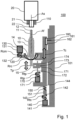
- Figure 1 schematically shows a side view of a cross section of a compounding system 100.
- the compounding system comprises a Luer coupling holder 110, a container holder 120, a rotation actuator 130, a translation actuator 140, bias means 150, and a controller.
- the compounding system may comprise a frame 101 arranged for providing a structure and/or mechanical reference to the compounding system and/or its features.
- the controller is not shown in figure 1 .
- the compounding system is arranged for dosing a compound in a container 10.
- the container may comprise a container body 13.
- the container body typically encloses a volume for holding the doses compound.
- the container may comprise a first Luer coupling part 11 arranged to the container body, and a first Luer coupling end 12 which is a section of the first Luer coupling part and arranged at a distal end of the first Luer coupling part relative to the container body.
- the first Luer coupling part and/or the first Luer coupling end have a first coupling axis Af.
- the first coupling axis typically defines the elongated axis and/or the symmetry axis of the first Luer coupling part and/or the first Luer coupling end.
- the Luer coupling holder is arranged for holding a second Luer coupling end 21.
- the Luer coupling holder may be arranged for holding a compound supply 20.
- the compound supply may be a vial or e.g. a tube to a larger reservoir. Alternatively, the tube may lead to a fluid valve allowing multiple reservoirs or vails to supply a compound or part of the compound.
- the compound, substances making up the compound, or parts of the compound are typically a fluid, a gel and/or a suspension.
- the compound supply may comprise a second Luer coupling part 21 arranged for providing the compound, substances making up the compound, or parts of the compound, and a second Luer coupling end 22 providing an opening for fluidly coupling to the first Luer coupling end and/or the first Luer coupling part.
- the second Luer coupling part and/or the second Luer coupling end have a second coupling axis As.
- the second coupling axis typically defines the elongated axis and/or the symmetry axis of the second Luer coupling part and/or the second Luer coupling end.
- the container holder is arranged for holding the container.
- the container may comprise flanges 14.
- the flanges typically extend from the container body.
- the flanges are typically used for gripping the container for manipulating, such as moving, the container.
- the container holder may be arranged for gripping the flanges for coupling the container holder and the container in a rotational and translational manner and/or direction.
- the Luer coupling holder and the container holder are arranged for aligning the first coupling axis and the second coupling axis.
- the rotation actuator is arranged for rotating the container holder relative to the Luer coupling holder substantially around the first coupling axis.
- the rotation actuator may comprise a rotation motor 131, and a gear wheel 132 driving the container holder.
- the rotation motor may be coupled with one end with the frame and with a driving axis to the gear wheel for rotating Rrc the gear wheel relative to the frame.
- the gear wheel may drive the container holder for rotating Rrc the container holder relative to the frame.
- the Luer coupling holder may be fixated relative to the frame.
- the rotation motor induces a rotation of the container therefore induces a rotation Rrc of the first Luer coupling end relative to the second Luer coupling end. Rotation is moving one object relative to another object around a rotation axis.
- the translation actuator is arranged for translating the container holder relative to the Luer coupling holder along the first coupling axis.
- the translation actuator may translate the container relative to the frame along the first coupling axis.
- the translation actuator may comprise a translation motor 141, a translation spindle 142, a translation spindle nut 143, and a translation slider 144.
- the translation motor is arranged for directly or indirectly turning, driving and/or rotating Rtc the translation spindle.
- the translation slider may translate along the frame in a translation direction Tc translating the container typically substantially equal to the first coupling axis.
- the translation slider is typically rotationally fixated to the frame.
- the slider may slide along the frame in a direction of the first coupling axis.
- the translation spindle nut is typically rotationally fixated to the slider.
- the translation motor may be fixated to the frame with one end and have an axis rotating Rtc relative to the frame.
- the translation spindle rotates, the translation spindle nut travels along the translation spindle for inducing a translation Tc of the translation spindle nut and may induce a translation Tc of the translation slider.
- Translating is moving one object relative to another object along a straight line or substantially straight line.
- the bias means are arranged for biasing the first Luer coupling end and the second Luer coupling end when in contact in a direction of the first coupling axis.
- the bias means may comprise a spring 151.
- the bias means such as the spring, may be arranged between the translation slider and the translation spindle nut.
- the bias means typically provide a rotational fixation of the translation slider and the translation spindle nut.
- the bias provided by the bias means remains the same.
- the bias provided by the bias means changes.
- the bias means typically provide a limited amount of translational freedom between the translation spindle nut and the translation slider.
- the translation slider may be translated or moved in a direction necessary for bringing the first Luer coupling end and the second Luer coupling end in contact and/or in a direction further pressing the first Luer coupling and the second Luer coupling end together.
- the effect of the bias means is that this translation induces a bias biasing the contacting the first Luer coupling end and the second Luer coupling end together or towards each other.
- the rotation actuator may be activated for establishing the Luer coupling between the first Luer coupling end and the second Luer coupling end.
- the translation actuator may be activated during this rotation loosely associated with the rate of rotation of the rotation actuator, or may even remain stationary or unpowered during rotation of the rotation actuator. This provides the advantage of simplifying or easing the control over the rotation actuator and the translation actuator.
- the compounding system comprises a position sensor 160.
- the position sensor is arranged for sensing a container holder position of the container holder relative to the Luer coupling holder along the first coupling axis and/or translation container direction Tc.
- the position sensor may comprise a detector 161, and a detector strip 162.
- the detector strip may be fixated on the translation slider.
- the detector may be fixated to the frame.
- the detector is typically arranged to the detector strip such that the position and/or the change of the position of the slider relative to the frame may be measured.
- the first Luer coupling end relative to the Luer container holder is known, predefined or can be deduced.
- the second Luer coupling end relative to the Luer coupling holder is known, predefined or can be deduced.
- a method for deducing when the first Luer coupling end and the second Luer coupling end contact may comprise the steps of: translating the first Luer coupling end and the second Luer coupling end towards each other; detecting during translating when the position sensor does not sense a change in position; and if no change of position is sensed optionally stopping translating towards each other.
- the position sensor does not sense a change in position
- the first Luer coupling end and the second Luer coupling end contact each other.
- the method may be stopped when the first Luer coupling end and the second Luer coupling end first make contact with each other. This advantageously allows to control the amount of bias and/or indentation provided by the bias means.
- the method may also comprise the steps of before translating towards each other, translating the first Luer coupling end and the second Luer coupling end away from each other; detecting during translating away from each other when the position sensor does sense a change in position; and if a change of position is sensed stopping translating away from each other.
- the position sensor does sense a change in position
- the first Luer coupling end and the second Luer coupling end do not contact each other.
- the first moment of contact may be determined even when the first Luer coupling end and the second Luer coupling end contact each other at the start of the method.
- the preceding additional method steps may also only be performed if when first translating the first Luer coupling end and the second Luer coupling end towards each other, it is detected that the first Luer coupling end and the second Luer coupling end are already in contact.
- the method may comprise the step of continuing translating the first Luer coupling end and the second Luer coupling end towards each other for a predefined distance and/or time. This step advantageously provides a specified or predetermined amount of bias and/or indentation.
- the container such as a syringe may comprise a plunger 15.
- the plunger is typically arranged partly in the container body for controlling the volume held in the container body.
- the compounding system may comprise container fill means 170.
- the container fill means are arranged for controlling the filling and/or volume contained in the container, typically the container body.
- the container fill means may comprise a plunger motor 171, a plunger spindle 172, a plunger holder 173, and a plunger slider 174.
- the plunger slider may be rotationally fixated to the translation slider.
- the plunger slider may be translationally and/or movable along the translation slider.
- the plunger holder is shaped and arranged for holding the plunger and/or any other means controlling the volume of the container.
- the plunger slider and the plunger holder may form a single body and are typically fixated relative to each other.
- the plunger motor may be fixated at one end to the translation slider.
- the plunger motor may directly or indirectly rotate Rtp or drive a plunger spindle.
- the plunger slider may comprise an opening with a thread engaging the plunger spindle. When the plunger spindle is rotated, the plunger slider and thus the plunger is translated Tp along an axis equal or substantially equal to the first coupling axis.
- Figure 2 schematically shows a perspective view of a compounding system 100. Parts of the compounding system are shown transparent. Parts of the compounding system are shown in a cross-sectional view. Parts of the compounding system are left out for clarity purposes only without impeding the disclosure of the invention.
- the translation actuator comprises a translation belt 145 for indirectly driving or rotating the translation spindle.
- the rotation actuator comprises a rotation belt 133 for indirectly driving or rotating the container holder.
- the container fill means comprise a plunger belt 175 for indirectly driving or rotating the plunger spindle.
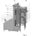
- Figure 3 schematically shows a perspective view of a compounding system 100. Parts of the compounding system are shown transparent. Parts of the compounding system are shown in a cross-sectional view. Parts of the compounding system are left out for clarity purposes only without impeding the disclosure of the invention.
- the bias means comprise a spring holder 152.
- the spring holder is fixated or an integral part of the translation slider.
- the spring holder comprises a through hole for arranging the translation spindle in this through hole.
- the through hole is stepped, such that the spring arranged in the through hole abuts on one end of the stepped through hole and abuts on the other end of the through hole on the translation spindle nut arranged on the other end of the stepped through hole.
- the translation spindle nut is arranged in the spring holder such that the translation spindle nut may translate inside the stepped through hole opening relative to the spring holder but is limited or prevented from rotating relative to the spring holder. This allows for a simple and effective bias means.
- the spring holder, spring and translation spindle nut are typically arranged such that gravity provides compression for simplifying the design of the bias means.
- Figure 4 schematically shows an embodiment of a computer program product 1000, computer readable medium 1010 and/or non-transitory computer readable storage medium according to the invention comprising computer readable code 1020.
- substantially herein, such as in “substantially all emission” or in “substantially consists”, will be understood by the person skilled in the art.
- the term “substantially” may also include embodiments with “entirely”, “completely”, “all”, etc. Hence, in embodiments the adjective substantially may also be removed.
- the term “substantially” may also relate to 90% or higher, such as 95% or higher, especially 99% or higher, even more especially 99.5% or higher, including 100%.
- the term “comprise” also includes embodiments wherein the term “comprises” means “consists of”.
- the term “functionally” is intended to cover variations in the feature to which it refers, and which variations are such that in the functional use of the feature, possibly in combination with other features it relates to in the invention, that combination of features is able to operate or function. For instance, if an antenna is functionally coupled or functionally connected to a communication device, received electromagnetic signals that are receives by the antenna can be used by the communication device.
- the word “functionally” as for instance used in “functionally parallel” is used to cover exactly parallel, but also the embodiments that are covered by the word “substantially” explained above.
- “functionally parallel” relates to embodiments that in operation function as if the parts are for instance parallel. This covers embodiments for which it is clear to a skilled person that it operates within its intended field of use as if it were parallel.
- the invention may be implemented by means of hardware comprising several distinct elements, and by means of a suitably programmed computer.
- device or apparatus claims enumerating several means, several of these means may be embodied by one and the same item of hardware.
- the mere fact that certain measures are recited in mutually different dependent claims does not indicate that a combination of these measures cannot be used to advantage.
- the invention further applies to an apparatus or device comprising one or more of the characterising features described in the description and/or shown in the attached drawings.
- the invention further pertains to a method or process comprising one or more of the characterising features described in the description and/or shown in the attached drawings.
- the invention also applies to computer programs, particularly computer programs on or in a carrier, adapted to put the invention into practice.
- the program may be in the form of a source code, a code intermediate source and an object code such as in a partially compiled form, or in any other form suitable for use in the implementation of the method according to the invention.
- a program may have many different architectural designs.
- a program code implementing the functionality of the method or system according to the invention may be sub-divided into one or more sub-routines. Many different ways of distributing the functionality among these sub-routines will be apparent to the skilled person.
- the sub-routines may be stored together in one executable file to form a self-contained program.
- Such an executable file may comprise computer-executable instructions, for example, processor instructions and/or interpreter instructions (e.g. Java interpreter instructions).
- one or more or all of the sub-routines may be stored in at least one external library file and linked with a main program either statically or dynamically, e.g. at run-time.
- the main program contains at least one call to at least one of the sub-routines.
- the sub-routines may also comprise function calls to each other.
- An embodiment relating to a computer program product comprises computer-executable instructions corresponding to each processing stage of at least one of the methods set forth herein. These instructions may be sub-divided into sub-routines and/or stored in one or more files that may be linked statically or dynamically.
- Another embodiment relating to a computer program product comprises computer-executable instructions corresponding to each means of at least one of the systems and/or products set forth herein. These instructions may be sub-divided into sub-routines and/or stored in one or more files that may be linked statically or dynamically.
- the carrier of a computer program may be any entity or device capable of carrying the program.
- the carrier may include a data storage, such as a ROM, for example, a CD ROM or a semiconductor ROM, or a magnetic recording medium, for example, a hard disk.
- the carrier may be a transmissible carrier such as an electric or optical signal, which may be conveyed via electric or optical cable or by radio or other means.
- the carrier may be constituted by such a cable or other device or means.
- the carrier may be an integrated circuit in which the program is embedded, the integrated circuit being adapted to perform, or used in the performance of, the relevant method.
Landscapes
- Health & Medical Sciences (AREA)
- General Health & Medical Sciences (AREA)
- Veterinary Medicine (AREA)
- Public Health (AREA)
- Animal Behavior & Ethology (AREA)
- Life Sciences & Earth Sciences (AREA)
- Pharmacology & Pharmacy (AREA)
- Medicinal Chemistry (AREA)
- Chemical & Material Sciences (AREA)
- Nutrition Science (AREA)
- Engineering & Computer Science (AREA)
- Mechanical Engineering (AREA)
- Infusion, Injection, And Reservoir Apparatuses (AREA)
- Medical Preparation Storing Or Oral Administration Devices (AREA)
- Details Of Rigid Or Semi-Rigid Containers (AREA)
Applications Claiming Priority (3)
| Application Number | Priority Date | Filing Date | Title |
|---|---|---|---|
| NL2029580 | 2021-11-01 | ||
| NL2031054A NL2031054B1 (en) | 2021-11-01 | 2022-02-23 | Compounding system |
| PCT/NL2022/050608 WO2023075600A1 (en) | 2021-11-01 | 2022-10-31 | Compounding system |
Publications (3)
| Publication Number | Publication Date |
|---|---|
| EP4426258A1 EP4426258A1 (en) | 2024-09-11 |
| EP4426258C0 EP4426258C0 (en) | 2025-05-21 |
| EP4426258B1 true EP4426258B1 (en) | 2025-05-21 |
Family
ID=84329772
Family Applications (1)
| Application Number | Title | Priority Date | Filing Date |
|---|---|---|---|
| EP22801241.5A Active EP4426258B1 (en) | 2021-11-01 | 2022-10-31 | Compounding system |
Country Status (6)
| Country | Link |
|---|---|
| US (1) | US12150913B2 (pl) |
| EP (1) | EP4426258B1 (pl) |
| CA (1) | CA3237021A1 (pl) |
| ES (1) | ES3030528T3 (pl) |
| PL (1) | PL4426258T3 (pl) |
| WO (1) | WO2023075600A1 (pl) |
Families Citing this family (3)
| Publication number | Priority date | Publication date | Assignee | Title |
|---|---|---|---|---|
| US12310923B2 (en) * | 2022-04-17 | 2025-05-27 | The Compounding Company B.V. | Compounding system |
| IT202300023685A1 (it) * | 2023-11-09 | 2025-05-09 | Sipar S R L | Dispositivo dosatore di infusione per la preparazione di farmaci |
| IT202300023688A1 (it) * | 2023-11-09 | 2025-05-09 | Sipar S R L | Dispositivo dosatore di estrazione per la preparazione di farmaci |
Family Cites Families (9)
| Publication number | Priority date | Publication date | Assignee | Title |
|---|---|---|---|---|
| US5884457A (en) * | 1997-02-05 | 1999-03-23 | Smithkline Beecham Corporation | Method and apparatus for automatically producing a plurality of sterile liquid filled delivery devices |
| AU2001290528A1 (en) * | 2000-08-10 | 2002-02-18 | Baxa Corporation | Method, system, and apparatus for handling, labeling, filling, and capping syringes |
| WO2007130809A2 (en) * | 2006-05-06 | 2007-11-15 | Volodymyr Brodskyy | An automatic injectable drug mixing device |
| ITUD20070093A1 (it) * | 2007-05-30 | 2008-11-30 | Cadel Daniele | Apparecchiatura per la preparazione automatica di un farmaco e relativo procedimento per la preparazione |
| EP2298270A1 (en) * | 2009-03-31 | 2011-03-23 | Panasonic Corporation | Medication mixing device and medication mixing method |
| CA2768985C (en) * | 2009-07-29 | 2020-03-10 | Icu Medical, Inc. | Fluid transfer devices and methods of use |
| IL202071A0 (en) * | 2009-11-12 | 2010-06-16 | Medimop Medical Projects Ltd | Module for screw threading syringe onto syringe port |
| ES2596708B1 (es) | 2015-07-08 | 2017-04-12 | Kiro Grifols S.L | Máquina y procedimiento para la preparación automática de sustancias de aplicación intravenosa |
| US12029704B2 (en) * | 2020-08-28 | 2024-07-09 | Omnicell, Inc. | Medication dosing systems and methods |
-
2022
- 2022-10-31 WO PCT/NL2022/050608 patent/WO2023075600A1/en not_active Ceased
- 2022-10-31 US US18/705,943 patent/US12150913B2/en active Active
- 2022-10-31 ES ES22801241T patent/ES3030528T3/es active Active
- 2022-10-31 CA CA3237021A patent/CA3237021A1/en active Pending
- 2022-10-31 PL PL22801241.5T patent/PL4426258T3/pl unknown
- 2022-10-31 EP EP22801241.5A patent/EP4426258B1/en active Active
Also Published As
| Publication number | Publication date |
|---|---|
| US12150913B2 (en) | 2024-11-26 |
| ES3030528T3 (en) | 2025-06-30 |
| CA3237021A1 (en) | 2023-05-04 |
| EP4426258C0 (en) | 2025-05-21 |
| US20240325250A1 (en) | 2024-10-03 |
| PL4426258T3 (pl) | 2025-07-28 |
| EP4426258A1 (en) | 2024-09-11 |
| WO2023075600A1 (en) | 2023-05-04 |
Similar Documents
| Publication | Publication Date | Title |
|---|---|---|
| EP4426258B1 (en) | Compounding system | |
| CA2767007C (en) | Drug delivery devices and related systems and methods | |
| KR100763050B1 (ko) | 액체 약품을 전달하기 위한 니들 카세트를 갖는 주입 장치 | |
| KR20150133723A (ko) | 주사기를 유체 분주 장치 내에 수용하기 위한 장치, 그를 위한 방법, 및 그러한 리셉터클의 사용법 | |
| EP4510991B1 (en) | Compounding system | |
| NL2031054B1 (en) | Compounding system | |
| KR20230057382A (ko) | Iv 조제를 위한 백 이송 기구 | |
| AU2014200160B2 (en) | Drug delivery devices and related systems and methods | |
| NL2033305B1 (en) | Compounding system | |
| NL2033522B1 (en) | Compounding system | |
| CN120435325A (zh) | 微型注射器驱动器 | |
| TW202513104A (zh) | 藥物輸送裝置(四) | |
| HK1167112A (en) | Drug delivery devices and related systems and methods | |
| HK1165340B (en) | Drug delivery devices and related systems and methods | |
| HK1189843B (en) | Infusion rotary peristaltic pump | |
| HK1182365B (en) | Improved automated medical liquid filling method |
Legal Events
| Date | Code | Title | Description |
|---|---|---|---|
| STAA | Information on the status of an ep patent application or granted ep patent |
Free format text: STATUS: UNKNOWN |
|
| STAA | Information on the status of an ep patent application or granted ep patent |
Free format text: STATUS: THE INTERNATIONAL PUBLICATION HAS BEEN MADE |
|
| PUAI | Public reference made under article 153(3) epc to a published international application that has entered the european phase |
Free format text: ORIGINAL CODE: 0009012 |
|
| STAA | Information on the status of an ep patent application or granted ep patent |
Free format text: STATUS: REQUEST FOR EXAMINATION WAS MADE |
|
| 17P | Request for examination filed |
Effective date: 20240505 |
|
| AK | Designated contracting states |
Kind code of ref document: A1 Designated state(s): AL AT BE BG CH CY CZ DE DK EE ES FI FR GB GR HR HU IE IS IT LI LT LU LV MC ME MK MT NL NO PL PT RO RS SE SI SK SM TR |
|
| GRAP | Despatch of communication of intention to grant a patent |
Free format text: ORIGINAL CODE: EPIDOSNIGR1 |
|
| STAA | Information on the status of an ep patent application or granted ep patent |
Free format text: STATUS: GRANT OF PATENT IS INTENDED |
|
| DAV | Request for validation of the european patent (deleted) | ||
| DAX | Request for extension of the european patent (deleted) | ||
| INTG | Intention to grant announced |
Effective date: 20241219 |
|
| GRAS | Grant fee paid |
Free format text: ORIGINAL CODE: EPIDOSNIGR3 |
|
| GRAA | (expected) grant |
Free format text: ORIGINAL CODE: 0009210 |
|
| STAA | Information on the status of an ep patent application or granted ep patent |
Free format text: STATUS: THE PATENT HAS BEEN GRANTED |
|
| AK | Designated contracting states |
Kind code of ref document: B1 Designated state(s): AL AT BE BG CH CY CZ DE DK EE ES FI FR GB GR HR HU IE IS IT LI LT LU LV MC ME MK MT NL NO PL PT RO RS SE SI SK SM TR |
|
| REG | Reference to a national code |
Ref country code: GB Ref legal event code: FG4D |
|
| REG | Reference to a national code |
Ref country code: CH Ref legal event code: EP |
|
| REG | Reference to a national code |
Ref country code: DE Ref legal event code: R096 Ref document number: 602022015042 Country of ref document: DE |
|
| REG | Reference to a national code |
Ref country code: IE Ref legal event code: FG4D |
|
| REG | Reference to a national code |
Ref country code: ES Ref legal event code: FG2A Ref document number: 3030528 Country of ref document: ES Kind code of ref document: T3 Effective date: 20250630 |
|
| U01 | Request for unitary effect filed |
Effective date: 20250526 |
|
| U07 | Unitary effect registered |
Designated state(s): AT BE BG DE DK EE FI FR IT LT LU LV MT NL PT RO SE SI Effective date: 20250605 |
|
| U20 | Renewal fee for the european patent with unitary effect paid |
Year of fee payment: 4 Effective date: 20250902 |
|
| PG25 | Lapsed in a contracting state [announced via postgrant information from national office to epo] |
Ref country code: NO Free format text: LAPSE BECAUSE OF FAILURE TO SUBMIT A TRANSLATION OF THE DESCRIPTION OR TO PAY THE FEE WITHIN THE PRESCRIBED TIME-LIMIT Effective date: 20250821 Ref country code: GR Free format text: LAPSE BECAUSE OF FAILURE TO SUBMIT A TRANSLATION OF THE DESCRIPTION OR TO PAY THE FEE WITHIN THE PRESCRIBED TIME-LIMIT Effective date: 20250822 |
|
| PGFP | Annual fee paid to national office [announced via postgrant information from national office to epo] |
Ref country code: PL Payment date: 20250911 Year of fee payment: 4 |
|
| PG25 | Lapsed in a contracting state [announced via postgrant information from national office to epo] |
Ref country code: HR Free format text: LAPSE BECAUSE OF FAILURE TO SUBMIT A TRANSLATION OF THE DESCRIPTION OR TO PAY THE FEE WITHIN THE PRESCRIBED TIME-LIMIT Effective date: 20250521 |
|
| PG25 | Lapsed in a contracting state [announced via postgrant information from national office to epo] |
Ref country code: RS Free format text: LAPSE BECAUSE OF FAILURE TO SUBMIT A TRANSLATION OF THE DESCRIPTION OR TO PAY THE FEE WITHIN THE PRESCRIBED TIME-LIMIT Effective date: 20250821 |
|
| PGFP | Annual fee paid to national office [announced via postgrant information from national office to epo] |
Ref country code: IE Payment date: 20250902 Year of fee payment: 4 |
|
| PG25 | Lapsed in a contracting state [announced via postgrant information from national office to epo] |
Ref country code: IS Free format text: LAPSE BECAUSE OF FAILURE TO SUBMIT A TRANSLATION OF THE DESCRIPTION OR TO PAY THE FEE WITHIN THE PRESCRIBED TIME-LIMIT Effective date: 20250921 |
|
| REG | Reference to a national code |
Ref country code: CH Ref legal event code: U11 Free format text: ST27 STATUS EVENT CODE: U-0-0-U10-U11 (AS PROVIDED BY THE NATIONAL OFFICE) Effective date: 20251101 |