EP4425959A1 - Ultrasonic wave generating device and ultrasonic wave generating system - Google Patents
Ultrasonic wave generating device and ultrasonic wave generating system Download PDFInfo
- Publication number
- EP4425959A1 EP4425959A1 EP22886977.2A EP22886977A EP4425959A1 EP 4425959 A1 EP4425959 A1 EP 4425959A1 EP 22886977 A EP22886977 A EP 22886977A EP 4425959 A1 EP4425959 A1 EP 4425959A1
- Authority
- EP
- European Patent Office
- Prior art keywords
- ultrasonic wave
- wave generation
- reflection surface
- generation source
- outer circumferential
- Prior art date
- Legal status (The legal status is an assumption and is not a legal conclusion. Google has not performed a legal analysis and makes no representation as to the accuracy of the status listed.)
- Pending
Links
Images


Classifications
-
- B—PERFORMING OPERATIONS; TRANSPORTING
- B06—GENERATING OR TRANSMITTING MECHANICAL VIBRATIONS IN GENERAL
- B06B—METHODS OR APPARATUS FOR GENERATING OR TRANSMITTING MECHANICAL VIBRATIONS OF INFRASONIC, SONIC, OR ULTRASONIC FREQUENCY, e.g. FOR PERFORMING MECHANICAL WORK IN GENERAL
- B06B1/00—Methods or apparatus for generating mechanical vibrations of infrasonic, sonic, or ultrasonic frequency
- B06B1/02—Methods or apparatus for generating mechanical vibrations of infrasonic, sonic, or ultrasonic frequency making use of electrical energy
-
- B—PERFORMING OPERATIONS; TRANSPORTING
- B06—GENERATING OR TRANSMITTING MECHANICAL VIBRATIONS IN GENERAL
- B06B—METHODS OR APPARATUS FOR GENERATING OR TRANSMITTING MECHANICAL VIBRATIONS OF INFRASONIC, SONIC, OR ULTRASONIC FREQUENCY, e.g. FOR PERFORMING MECHANICAL WORK IN GENERAL
- B06B1/00—Methods or apparatus for generating mechanical vibrations of infrasonic, sonic, or ultrasonic frequency
- B06B1/02—Methods or apparatus for generating mechanical vibrations of infrasonic, sonic, or ultrasonic frequency making use of electrical energy
- B06B1/06—Methods or apparatus for generating mechanical vibrations of infrasonic, sonic, or ultrasonic frequency making use of electrical energy operating with piezoelectric effect or with electrostriction
- B06B1/0644—Methods or apparatus for generating mechanical vibrations of infrasonic, sonic, or ultrasonic frequency making use of electrical energy operating with piezoelectric effect or with electrostriction using a single piezoelectric element
- B06B1/0655—Methods or apparatus for generating mechanical vibrations of infrasonic, sonic, or ultrasonic frequency making use of electrical energy operating with piezoelectric effect or with electrostriction using a single piezoelectric element of cylindrical shape
-
- A—HUMAN NECESSITIES
- A61—MEDICAL OR VETERINARY SCIENCE; HYGIENE
- A61B—DIAGNOSIS; SURGERY; IDENTIFICATION
- A61B8/00—Diagnosis using ultrasonic, sonic or infrasonic waves
- A61B8/44—Constructional features of the ultrasonic, sonic or infrasonic diagnostic device
- A61B8/4483—Constructional features of the ultrasonic, sonic or infrasonic diagnostic device characterised by features of the ultrasound transducer
- A61B8/4494—Constructional features of the ultrasonic, sonic or infrasonic diagnostic device characterised by features of the ultrasound transducer characterised by the arrangement of the transducer elements
-
- B—PERFORMING OPERATIONS; TRANSPORTING
- B06—GENERATING OR TRANSMITTING MECHANICAL VIBRATIONS IN GENERAL
- B06B—METHODS OR APPARATUS FOR GENERATING OR TRANSMITTING MECHANICAL VIBRATIONS OF INFRASONIC, SONIC, OR ULTRASONIC FREQUENCY, e.g. FOR PERFORMING MECHANICAL WORK IN GENERAL
- B06B3/00—Methods or apparatus specially adapted for transmitting mechanical vibrations of infrasonic, sonic, or ultrasonic frequency
-
- B—PERFORMING OPERATIONS; TRANSPORTING
- B06—GENERATING OR TRANSMITTING MECHANICAL VIBRATIONS IN GENERAL
- B06B—METHODS OR APPARATUS FOR GENERATING OR TRANSMITTING MECHANICAL VIBRATIONS OF INFRASONIC, SONIC, OR ULTRASONIC FREQUENCY, e.g. FOR PERFORMING MECHANICAL WORK IN GENERAL
- B06B3/00—Methods or apparatus specially adapted for transmitting mechanical vibrations of infrasonic, sonic, or ultrasonic frequency
- B06B3/04—Methods or apparatus specially adapted for transmitting mechanical vibrations of infrasonic, sonic, or ultrasonic frequency involving focusing or reflecting
-
- G—PHYSICS
- G10—MUSICAL INSTRUMENTS; ACOUSTICS
- G10K—SOUND-PRODUCING DEVICES; METHODS OR DEVICES FOR PROTECTING AGAINST, OR FOR DAMPING, NOISE OR OTHER ACOUSTIC WAVES IN GENERAL; ACOUSTICS NOT OTHERWISE PROVIDED FOR
- G10K11/00—Methods or devices for transmitting, conducting or directing sound in general; Methods or devices for protecting against, or for damping, noise or other acoustic waves in general
- G10K11/18—Methods or devices for transmitting, conducting or directing sound
- G10K11/26—Sound-focusing or directing, e.g. scanning
- G10K11/28—Sound-focusing or directing, e.g. scanning using reflection, e.g. parabolic reflectors
-
- H—ELECTRICITY
- H04—ELECTRIC COMMUNICATION TECHNIQUE
- H04R—LOUDSPEAKERS, MICROPHONES, GRAMOPHONE PICK-UPS OR LIKE ACOUSTIC ELECTROMECHANICAL TRANSDUCERS; ELECTRIC HEARING AIDS; PUBLIC ADDRESS SYSTEMS
- H04R1/00—Details of transducers, loudspeakers or microphones
- H04R1/20—Arrangements for obtaining desired frequency or directional characteristics
- H04R1/32—Arrangements for obtaining desired frequency or directional characteristics for obtaining desired directional characteristic only
- H04R1/34—Arrangements for obtaining desired frequency or directional characteristics for obtaining desired directional characteristic only by using a single transducer with sound reflecting, diffracting, directing or guiding means
-
- H—ELECTRICITY
- H04—ELECTRIC COMMUNICATION TECHNIQUE
- H04R—LOUDSPEAKERS, MICROPHONES, GRAMOPHONE PICK-UPS OR LIKE ACOUSTIC ELECTROMECHANICAL TRANSDUCERS; ELECTRIC HEARING AIDS; PUBLIC ADDRESS SYSTEMS
- H04R17/00—Piezoelectric transducers; Electrostrictive transducers
-
- A—HUMAN NECESSITIES
- A61—MEDICAL OR VETERINARY SCIENCE; HYGIENE
- A61N—ELECTROTHERAPY; MAGNETOTHERAPY; RADIATION THERAPY; ULTRASOUND THERAPY
- A61N7/00—Ultrasound therapy
- A61N2007/0039—Ultrasound therapy using microbubbles
-
- A—HUMAN NECESSITIES
- A61—MEDICAL OR VETERINARY SCIENCE; HYGIENE
- A61N—ELECTROTHERAPY; MAGNETOTHERAPY; RADIATION THERAPY; ULTRASOUND THERAPY
- A61N7/00—Ultrasound therapy
- A61N2007/0052—Ultrasound therapy using the same transducer for therapy and imaging
-
- A—HUMAN NECESSITIES
- A61—MEDICAL OR VETERINARY SCIENCE; HYGIENE
- A61N—ELECTROTHERAPY; MAGNETOTHERAPY; RADIATION THERAPY; ULTRASOUND THERAPY
- A61N7/00—Ultrasound therapy
- A61N2007/0056—Beam shaping elements
-
- A—HUMAN NECESSITIES
- A61—MEDICAL OR VETERINARY SCIENCE; HYGIENE
- A61N—ELECTROTHERAPY; MAGNETOTHERAPY; RADIATION THERAPY; ULTRASOUND THERAPY
- A61N7/00—Ultrasound therapy
- A61N2007/0056—Beam shaping elements
- A61N2007/0069—Reflectors
-
- A—HUMAN NECESSITIES
- A61—MEDICAL OR VETERINARY SCIENCE; HYGIENE
- A61N—ELECTROTHERAPY; MAGNETOTHERAPY; RADIATION THERAPY; ULTRASOUND THERAPY
- A61N7/00—Ultrasound therapy
Definitions
- the present invention relates to an ultrasonic wave generation device and an ultrasonic wave generation system.
- Patent Document 1 describes an ultrasonic wave generation device including: an ultrasonic wave generation source which generates an ultrasonic wave; an ultrasonic wave converging part which converges the ultrasonic wave generated by the ultrasonic wave generation source; and a waveguide which allows transmission of the ultrasonic wave converged by the ultrasonic wave converging part.
- the ultrasonic wave generated by the ultrasonic wave generation source is transmitted to the front end of the waveguide.
- Patent Document 1 WO2006/028249
- an ultrasonic wave generation source of an ultrasonic wave generation device such as one described above is joined to an ultrasonic wave converging part by using an adhesive or the like.
- the adhesive is evenly spread on adhesion surfaces of the ultrasonic wave generation source and the ultrasonic wave converging part.
- the intensity of an ultrasonic wave might decrease owing to the adhesive sticking out.
- the present invention has been completed in view of the above circumstance, and an object of the present invention is to provide an ultrasonic wave generation device and an ultrasonic wave generation system that can inhibit the intensity of an ultrasonic wave from decreasing owing to an adhesive.
- An ultrasonic wave generation device of present invention 1 includes: an ultrasonic wave generation source configured to generate an ultrasonic wave; an ultrasonic wave converging part configured to converge the ultrasonic wave generated from the ultrasonic wave generation source; and a waveguide configured to allow transmission therethrough of the ultrasonic wave converged by the ultrasonic wave converging part.
- the ultrasonic wave converging part has a first reflection surface located to be opposed to the ultrasonic wave generation source and a second reflection surface located to be opposed to the first reflection surface.
- the first reflection surface is a curved surface protruding to a side opposite to the ultrasonic wave generation source and reflects the ultrasonic wave that has been generated from the ultrasonic wave generation source, toward the second reflection surface.
- the second reflection surface is a curved surface protruding to a side opposite to the first reflection surface and reflects the ultrasonic wave that has been reflected by the first reflection surface, toward the waveguide so as to introduce the ultrasonic wave into the waveguide.
- the ultrasonic wave generation source encloses a circumference, of the second reflection surface, in a radial direction orthogonal to a direction in which the ultrasonic wave generation source and the first reflection surface are opposed to each other.
- the ultrasonic wave converging part is adhered to the ultrasonic wave generation source by using an adhesive.
- the adhesive is, on an inner circumferential side relative to the ultrasonic wave generation source, provided in a region on an outer circumferential side relative to the third imaginary line.
- An ultrasonic wave generation device of present invention 2 includes: an ultrasonic wave generation source configured to generate an ultrasonic wave; an ultrasonic wave converging part configured to converge the ultrasonic wave generated from the ultrasonic wave generation source; and a waveguide configured to allow transmission therethrough of the ultrasonic wave converged by the ultrasonic wave converging part.
- the ultrasonic wave converging part has a first reflection surface located to be opposed to the ultrasonic wave generation source and a second reflection surface located to be opposed to the first reflection surface.
- the first reflection surface is a curved surface protruding to a side opposite to the ultrasonic wave generation source and reflects the ultrasonic wave that has been generated from the ultrasonic wave generation source, toward the second reflection surface.
- the second reflection surface is a curved surface protruding to a side opposite to the first reflection surface and reflects the ultrasonic wave that has been reflected by the first reflection surface, toward the waveguide so as to introduce the ultrasonic wave into the waveguide.
- the ultrasonic wave generation source encloses a circumference, of the second reflection surface, in a radial direction orthogonal to a direction in which the ultrasonic wave generation source and the first reflection surface are opposed to each other.
- the ultrasonic wave converging part is adhered to the ultrasonic wave generation source by using an adhesive.
- the adhesive adhering the ultrasonic wave converging part and the ultrasonic wave generation source to each other is provided also on an outer circumferential side relative to the ultrasonic wave generation source and is not provided on an inner circumferential side of the first reflection surface relative to the first imaginary line.
- the adhesive is not provided in a region, of the second reflection surface, on the inner circumferential side relative to the third imaginary line (a region, of the second reflection surface, in which a particularly intense ultrasonic wave is applied). Therefore, the intensity of an ultrasonic wave can be inhibited from decreasing owing to the adhesive.
- the adhesive is not provided in a region, of the first reflection surface, on the inner circumferential side relative to a first imaginary plane (a region, of the first reflection surface, in which a particularly intense ultrasonic wave is applied). Therefore, the intensity of an ultrasonic wave can be inhibited from decreasing owing to the adhesive.
- the ultrasonic wave generation device of present invention 1 may be configured such that: an accumulation space for the adhesive is provided between an inner circumferential edge of the ultrasonic wave generation source and an outer circumferential edge of the second reflection surface; and the accumulation space extends along an adhesion surface and has a size that allows the adhesive to be accumulated in the accumulation space.
- the ultrasonic wave generation device of present invention 1 may be configured such that a step surface extending in a direction intersecting with an adhesion surface is formed between an inner circumferential edge of the ultrasonic wave generation source and an outer circumferential edge of the second reflection surface.
- a step surface extending in a direction intersecting with an adhesion surface is formed between an inner circumferential edge of the ultrasonic wave generation source and an outer circumferential edge of the second reflection surface.
- the ultrasonic wave generation device of present invention 1 may be configured such that a wall protruding in a direction intersecting with an adhesion surface is provided between an inner circumferential edge of the ultrasonic wave generation source and an outer circumferential edge of the second reflection surface.
- the adhesive sticking out from the inner circumferential edge of the ultrasonic wave generation source stays on the ultrasonic wave generation source side owing to the wall, whereby the adhesive can be made less likely to be adhered to the second reflection surface than in a case where the wall is not provided.
- the ultrasonic wave generation device of present invention 1 may be configured such that a groove recessed in a direction intersecting with an adhesion surface is provided between an inner circumferential edge of the ultrasonic wave generation source and an outer circumferential edge of the second reflection surface.
- a groove recessed in a direction intersecting with an adhesion surface is provided between an inner circumferential edge of the ultrasonic wave generation source and an outer circumferential edge of the second reflection surface.
- the ultrasonic wave generation device of present invention 1 may be configured such that the groove is formed on the ultrasonic wave generation source side relative to an imaginary plane formed between the first imaginary line and the focus by all the second imaginary lines.
- the groove does not overlap with a propagation region for an ultrasonic wave converging from the first reflection surface to the focus. Therefore, the groove does not hinder propagation of the ultrasonic wave converging from the first reflection surface to the focus.
- the ultrasonic wave generation device of present invention 2 may be configured such that a wall protruding in a direction intersecting with an adhesion surface is provided on the outer circumferential side relative to the outer circumferential edge of the ultrasonic wave generation source. With such a configuration, the adhesive sticking out from the outer circumferential edge of the ultrasonic wave generation source stays on the ultrasonic wave generation source side owing to the wall, whereby the adhesive can be made less likely to be adhered to the first reflection surface than in a case where the wall is not provided.
- the ultrasonic wave generation device of present invention 2 may be configured such that a groove recessed in a direction intersecting with an adhesion surface is provided on the outer circumferential side relative to the outer circumferential edge of the ultrasonic wave generation source.
- An ultrasonic wave generation device 10 in the present embodiment is used for an ultrasonograph, an ultrasonic treatment device, a cavitation generator, or the like.
- the ultrasonic wave generation device 10 includes an ultrasonic wave generation source 11, an ultrasonic wave converging part 12, and a waveguide 13.
- the ultrasonic wave generation source 11 generates an ultrasonic wave.
- the ultrasonic wave converging part 12 converges the ultrasonic wave generated from the ultrasonic wave generation source 11.
- the waveguide 13 allows transmission therethrough of the ultrasonic wave converged by the ultrasonic wave converging part 12.
- the ultrasonic wave transmitted through the waveguide 13 is applied to an object.
- the object is not particularly limited and may be, for example, the inside of a living body.
- the ultrasonic wave applied to the object is reflected by the object and returned to the inside of the waveguide 13 as an ultrasonic wave carrying image information about the object.
- the ultrasonic wave carrying the image information about the object is returned to the ultrasonic wave generation source 11 through the waveguide 13 and the ultrasonic wave converging part 12.
- An electric signal based on the ultrasonic wave carrying the image information is received by a signal transmission/reception circuit, and the image information included in the received signal is displayed on a signal display device.
- a technology for displaying an image on the basis of such an ultrasonic wave including image information a known technology employed for an ultrasonograph or the like can be employed.
- the ultrasonic wave generation source 11 is, for example, a piezoelectric element.
- the ultrasonic wave generation source 11 is formed in the shape of a plate having a predetermined thickness dimension.
- the ultrasonic wave generation source 11 has a first main surface 14 and a second main surface 15 on a side opposite to the first main surface 14. Electrodes (not shown) are disposed on the first main surface 14 and the second main surface 15.
- the ultrasonic wave generation source 11 generates an ultrasonic wave when receiving an electric signal from a power supply device 50 (see Fig. 8 ).
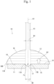
- the ultrasonic wave generated from the ultrasonic wave generation source 11 is a plane wave that advances straight in a direction indicated by an arrow A2 as shown in Fig. 1 .
- the arrow A2 indicates the advancing direction of the ultrasonic wave generated from the ultrasonic wave generation source 11.
- the arrow A2 is parallel to an axis A1.
- the ultrasonic wave generation source 11 generates an ultrasonic wave having, for example, a frequency equal to or higher than 30 kHz.
- the direction indicated by the arrow A2 in Fig. 1 is defined as an upward direction, and the direction opposite thereto is defined as a downward direction.
- the ultrasonic wave converging part 12 is formed of a solid metal (for example, duralumin).
- the ultrasonic wave converging part 12 has a first reflection surface 16 and a second reflection surface 17.
- the first reflection surface 16 is located to be opposed to the ultrasonic wave generation source 11.
- a direction in which the first reflection surface 16 and the ultrasonic wave generation source 11 are opposed to each other is parallel to the direction in which the axis A1 extends.
- the first reflection surface 16 is a paraboloid protruding to the upper side (the side opposite to the ultrasonic wave generation source 11) as seen from outside of the ultrasonic wave converging part 12.
- the first reflection surface 16 has a recessed shape as seen from inside of the ultrasonic wave converging part 12.
- a center portion of the first reflection surface 16 is located above an outer circumferential edge 16B of the first reflection surface 16.
- the first reflection surface 16 is a paraboloid of revolution about the axis A1.
- the second reflection surface 17 is located to be opposed to the first reflection surface 16.
- the second reflection surface 17 is a paraboloid protruding to the lower side (the side opposite to the first reflection surface 16) as seen from outside of the ultrasonic wave converging part 12.
- the second reflection surface 17 has a recessed shape as seen from inside of the ultrasonic wave converging part 12.
- a center portion of the second reflection surface 17 is located below an outer circumferential edge 17B of the second reflection surface 17.
- the second reflection surface 17 is a paraboloid of revolution about the axis A1.
- the waveguide 13 has the shape of a solid pillar.
- the waveguide 13 extends upward along the axis A1 from the center portion of the first reflection surface 16.
- a cross section, of the waveguide 13, orthogonal to the axis A1 has a circular shape about the axis A1.
- a diameter dimension B1, in a direction orthogonal to the axis A1, of the waveguide 13 is smaller than a diameter dimension B2, in the direction orthogonal to the axis A1, of the second reflection surface 17.
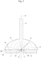
- the ultrasonic wave generated from the ultrasonic wave generation source 11 is reflected by the first reflection surface 16 and converged to a focus Fs for the first reflection surface 16, as shown in Fig. 2 .
- the ultrasonic wave having passed through the focus Fs is reflected by the second reflection surface 17 and converged to a focus Fs for the second reflection surface 17.
- the focus Fs for the second reflection surface 17 is identical to the focus Fs for the first reflection surface 16.
- the intensity of an ultrasonic wave per unit area of the second reflection surface 17 is higher than the intensity of an ultrasonic wave per unit area of the first reflection surface 16.
- the ultrasonic wave reflected by the second reflection surface 17 and having passed through the focus Fs is introduced into the waveguide 13 as a plane wave.
- the focus Fs is located on the axis A1.
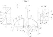
- the ultrasonic wave generation source 11 encloses a circumference of the second reflection surface 17 as shown in Fig. 3 and Fig. 4 .
- the ultrasonic wave generation source 11 has an annular shape about the axis A1.
- An inner circumferential edge 11A of the ultrasonic wave generation source 11 is apart from the outer circumferential edge 17B of the second reflection surface 17 outward in a radial direction orthogonal to the axis A1.
- An outer circumferential edge 11B of the ultrasonic wave generation source 11 is apart from the outer circumferential edge 16B of the first reflection surface 16 inward in the radial direction orthogonal to the axis A1.
- the inner circumferential edge 11A and the outer circumferential edge 11B of the ultrasonic wave generation source 11 are the outer circumferential edge and the inner circumferential edge of the first main surface 14, respectively.
- the outer circumferential edge 16B of the first reflection surface 16 and the outer circumferential edge 17B of the second reflection surface 17 have circular shapes that are concentric about the axis A1.
- the area of the second reflection surface 17 is smaller than the area of the first reflection surface 16.
- the ultrasonic wave converging part 12 has an adhesion surface 18 to be adhered to the ultrasonic wave generation source 11.
- the adhesion surface 18 spreads, outward in the radial direction orthogonal to the axis A1, from the outer circumferential edge 17B of the second reflection surface 17 to the outer circumferential edge 16B of the first reflection surface 16.
- the adhesion surface 18 is a flat surface orthogonal to the axis A1.
- the adhesion surface 18 has an annular shape so as to enclose the circumference of the second reflection surface 17, about the axis A1.
- the ultrasonic wave converging part 12 is adhered to the ultrasonic wave generation source 11 by using an adhesive 20.
- the adhesive 20 has a characteristic of allowing propagation of an ultrasonic wave.
- the adhesive 20 includes: an adhesion layer (not shown) disposed between the first main surface 14 of the ultrasonic wave generation source 11 and the adhesion surface 18 of the ultrasonic wave converging part 12; and an excess portion 21 sticking out from the first main surface 14.
- the adhesion layer is thin and spreads over the entirety of the first main surface 14.
- air bubbles that are formed are desirably reduced as much as possible, but air bubbles may be contained to some extent.
- the excess portion 21 prevents stress from being concentrated on an outer edge portion of the adhesion layer. Consequently, the ultrasonic wave generation source 11 can be inhibited from peeling from the outer edge portion of the adhesion layer.
- the ultrasonic wave converging part 12 has an inner accumulation space 23 and an outer accumulation space 24 as accumulation spaces for the adhesive 20.
- the inner accumulation space 23 and the outer accumulation space 24 extend along the adhesion surface 18. In other words, the inner accumulation space 23 and the outer accumulation space 24 are portions of the adhesion surface 18.
- the inner accumulation space 23 is provided on the inner circumferential side relative to the ultrasonic wave generation source 11.
- the inner accumulation space 23 is a portion, of the adhesion surface 18, that is located between the inner circumferential edge 11A of the ultrasonic wave generation source 11 and the outer circumferential edge 17B of the second reflection surface 17.
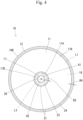
- the inner accumulation space 23 has an annular shape about the axis A1 as shown in Fig. 4 .
- the inner accumulation space 23 encloses the outer circumferential side of the second reflection surface 17.
- a width dimension (a diameter dimension in the direction orthogonal to the axis A1) B3 of the inner accumulation space 23 is fixed over the entire circumference thereof.
- the inner accumulation space 23 has a size that allows the corresponding excess portion 21 of the adhesive 20 to be accumulated therein.
- the outer accumulation space 24 is provided on the outer circumferential side relative to the ultrasonic wave generation source 11.
- the outer accumulation space 24 is a portion, of the adhesion surface 18, that is located between the outer circumferential edge 11B of the ultrasonic wave generation source 11 and the outer circumferential edge 16B of the first reflection surface 16.
- the outer accumulation space 24 has an annular shape about the axis A1 as shown in Fig. 4 .
- the outer accumulation space 24 encloses the outer circumferential side of the ultrasonic wave generation source 11.
- a width dimension (a diameter dimension in the direction orthogonal to the axis A1) B4 of the outer accumulation space 24 is fixed over the entire circumference thereof.
- the outer accumulation space 24 has a size that allows the corresponding excess portion 21 of the adhesive 20 to be accumulated therein.
- the excess portion 21 of the adhesive 20 stays.
- the excess portion 21 of the adhesive 20 is not provided in a specific region 26 of the second reflection surface 17.
- the specific region 26 of the second reflection surface 17 is a region, of the second reflection surface 17, in which a particularly intense ultrasonic wave is applied.
- the corresponding excess portion 21 of the adhesive 20 stays.
- the excess portion 21 of the adhesive 20 is not provided in a specific region 27 of the first reflection surface 16.
- the specific region 27 of the first reflection surface 16 is a region, of the first reflection surface 16, in which a particularly intense ultrasonic wave is applied.
- the specific region 26 of the second reflection surface 17 and the specific region 27 of the first reflection surface 16 will be described by defining a first imaginary line L1, second imaginary lines L2, and a third imaginary line L3.
- the first imaginary line L1 is an imaginary line on the first reflection surface 16.
- the first imaginary line L1 is a line obtained by projecting the outer circumferential edge 11B of the ultrasonic wave generation source 11 onto the first reflection surface 16 along the advancing direction of the ultrasonic wave generated from the ultrasonic wave generation source 11.
- the first imaginary line L1 overlaps with the outer circumferential edge 11B of the ultrasonic wave generation source 11, as seen from below the ultrasonic wave generation device 10.
- the first imaginary line L1 has a circular shape about the axis A1 on the first reflection surface 16.
- the specific region 27 of the first reflection surface 16 is a region on the inner circumferential side of the first reflection surface 16 relative to the first imaginary line L1.
- the second imaginary lines L2 are straight lines passing through points on the first imaginary line L1 and the focus Fs for the first reflection surface 16. Each of the second imaginary lines L2 extends obliquely downward from the first imaginary line L1 toward the focus Fs as shown in Fig. 3 .
- the third imaginary line L3 is an imaginary line on the second reflection surface 17.
- the third imaginary line L3 is formed by intersection points between the second reflection surface 17 and all the second imaginary lines L2.
- the third imaginary line L3 has a circular shape about the axis A1 on the second reflection surface 17.
- the third imaginary line L3 is located on the inner circumferential side relative to the outer circumferential edge 17B of the second reflection surface 17.
- the specific region 26 of the second reflection surface 17 is a region, of the second reflection surface 17, that is located inward of the third imaginary line L3.
- the ultrasonic wave generation device 10 in embodiment 1 includes the ultrasonic wave generation source 11, the ultrasonic wave converging part 12, and the waveguide 13.
- the ultrasonic wave generation source 11 generates an ultrasonic wave.
- the ultrasonic wave converging part 12 converges the ultrasonic wave generated from the ultrasonic wave generation source 11.
- the waveguide 13 allows transmission therethrough of the ultrasonic wave converged by the ultrasonic wave converging part 12.
- the ultrasonic wave converging part 12 has the first reflection surface 16 having a parabolic shape and the second reflection surface 17 having a parabolic shape.
- the first reflection surface 16 is located to be opposed to the ultrasonic wave generation source 11.
- the second reflection surface 17 is located to be opposed to the first reflection surface 16.
- the first reflection surface 16 reflects the ultrasonic wave that has been generated from the ultrasonic wave generation source 11, toward the second reflection surface 17.
- the second reflection surface 17 reflects the ultrasonic wave that has been reflected by the first reflection surface 16, toward the waveguide 13 so as to introduce the ultrasonic wave into the waveguide 13.
- the ultrasonic wave generation source 11 encloses a circumference, of the second reflection surface 17, in the radial direction orthogonal to the direction in which the ultrasonic wave generation source 11 and the first reflection surface 16 are opposed to each other.
- the ultrasonic wave converging part 12 is adhered to the ultrasonic wave generation source 11 by using the adhesive 20.
- the adhesive 20 is, on the inner circumferential side relative to the ultrasonic wave generation source 11, provided in a region on the outer circumferential side relative to the third imaginary line L3.
- the adhesive 20 is not provided in a region, of the second reflection surface 17, on the inner circumferential side relative to the third imaginary line L3 (a region, of the second reflection surface 17, in which a particularly intense ultrasonic wave is applied). Therefore, the intensity of an ultrasonic wave can be inhibited from decreasing owing to the adhesive 20.
- the adhesive 20 adhering the ultrasonic wave converging part 12 and the ultrasonic wave generation source 11 to each other is provided also on the outer circumferential side relative to the ultrasonic wave generation source 11.
- the adhesive 20 is not provided on the inner circumferential side of the first reflection surface 16 relative to the first imaginary line L1. With this configuration, the adhesive 20 is not provided in a region, of the first reflection surface 16, in which a particularly intense ultrasonic wave is applied, whereby the intensity of an ultrasonic wave can be inhibited from decreasing owing to the adhesive 20.
- the inner accumulation space 23 for the adhesive 20 is provided between the inner circumferential edge 11A of the ultrasonic wave generation source 11 and the outer circumferential edge 17B of the second reflection surface 17.
- the inner accumulation space 23 extends along the adhesion surface 18 and has a size that allows the adhesive 20 to be accumulated in the inner accumulation space 23. With this configuration, the adhesive 20 sticking out to the inner circumferential side of the ultrasonic wave generation source 11 is accumulated in the inner accumulation space 23, whereby the adhesive 20 can be made less likely to be adhered to the second reflection surface 17.
- the outer accumulation space 24 for the adhesive 20 is provided between the outer circumferential edge 11B of the ultrasonic wave generation source 11 and the outer circumferential edge 16B of the first reflection surface 16.
- the outer accumulation space 24 extends along the adhesion surface 18 and has a size that allows the adhesive 20 to be accumulated in the outer accumulation space 24. With this configuration, the adhesive 20 sticking out from the outer circumferential side of the ultrasonic wave generation source 11 is accumulated in the outer accumulation space 24, whereby the adhesive 20 can be made less likely to be adhered to the first reflection surface 16.
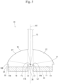
- the ultrasonic wave generation device 10 in the present embodiment differs from that in embodiment 1 in that an inner step surface 31 and an outer step surface 32 are formed on the inner circumferential side and the outer circumferential side relative to the ultrasonic wave generation source 11.
- the same components as those in embodiment 1 are denoted by the same reference characters, and repetitive descriptions thereof are omitted.
- the ultrasonic wave generation device includes: the ultrasonic wave generation source 11 which generates an ultrasonic wave; the ultrasonic wave converging part 12 which converges the ultrasonic wave generated from the ultrasonic wave generation source 11; and the waveguide 13 which allows transmission therethrough of the ultrasonic wave converged by the ultrasonic wave converging part 12.
- the excess portion (not shown) of the adhesive 20, on the inner circumferential side relative to the ultrasonic wave generation source 11, is provided in the region on the outer circumferential side relative to the third imaginary line L3, and the excess portion (not shown) of the adhesive 20, on the outer circumferential side relative to the ultrasonic wave generation source 11, is not provided on the inner circumferential side of the first reflection surface 16 relative to the first imaginary line L1.
- the inner step surface 31 is provided on the inner circumferential side relative to the ultrasonic wave generation source 11.
- the inner step surface 31 is provided at a center portion of the adhesion surface 18.
- the inner step surface 31 is provided between the inner circumferential edge 11A of the ultrasonic wave generation source 11 and the outer circumferential edge 17B of the second reflection surface 17.
- the inner step surface 31 extends upward from the adhesion surface 18 in a direction orthogonal to the adhesion surface 18.
- the inner step surface 31 has a cylindrical shape about the axis A1.
- the upper edge of the inner step surface 31 is the outer circumferential edge 17B of the second reflection surface 17.
- the lower edge of the inner step surface 31 is the inner circumferential edge 11A of the ultrasonic wave generation source 11.
- the outer step surface 32 is provided on the outer circumferential side relative to the ultrasonic wave generation source 11.
- the outer step surface 32 is provided at an outer edge portion of the adhesion surface 18.
- the outer step surface 32 extends upward from the adhesion surface 18 in the direction orthogonal to the adhesion surface 18.
- the outer step surface 32 has a cylindrical shape about the axis A1.
- the upper edge of the outer step surface 32 is located inward of the outer circumferential edge 16B of the first reflection surface 16.
- a space 33 is provided between the upper edge of the outer step surface 32 and the outer circumferential edge 16B of the first reflection surface 16.
- the space 33 has a flat surface orthogonal to the axis A1.
- the lower edge of the outer step surface 32 is the outer circumferential edge 11B of the ultrasonic wave generation source 11.
- the inner step surface 31 and the outer step surface 32 each extending in a direction intersecting with the adhesion surface 18 are formed on the inner circumferential side and the outer circumferential side, respectively, relative to the ultrasonic wave generation source 11.
- the adhesive 20 sticking out to the inner circumferential side of the ultrasonic wave generation source 11 is adhered to the inner step surface 31, whereby the adhesive 20 can be made less likely to be adhered to the second reflection surface 17.
- the adhesive 20 sticking out to the outer circumferential side of the ultrasonic wave generation source 11 is adhered to the outer step surface 32, whereby the adhesive 20 can be made less likely to be adhered to the first reflection surface 16.
- the adhesive 20 is, on the inner circumferential side relative to the ultrasonic wave generation source 11, provided in the region on the outer circumferential side relative to the third imaginary line L3, and the adhesive 20 is, on the outer circumferential side relative to the ultrasonic wave generation source 11, not provided on the inner circumferential side of the first reflection surface 16 relative to the first imaginary line L1. Therefore, the intensity of an ultrasonic wave can be inhibited from decreasing owing to the adhesive 20.
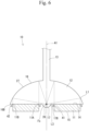
- the ultrasonic wave generation device 10 in the present embodiment differs from that in embodiment 1 in that an inner wall 41 and an outer wall 42 are provided on the inner circumferential side and the outer circumferential side, respectively, relative to the ultrasonic wave generation source 11.
- the same components as those in embodiment 1 are denoted by the same reference characters, and repetitive descriptions thereof are omitted.
- the ultrasonic wave generation device includes: the ultrasonic wave generation source 11 which generates an ultrasonic wave; the ultrasonic wave converging part 12 which converges the ultrasonic wave generated from the ultrasonic wave generation source 11; and the waveguide 13 which allows transmission therethrough of the ultrasonic wave converged by the ultrasonic wave converging part 12.
- the excess portion (not shown) of the adhesive 20, on the inner circumferential side relative to the ultrasonic wave generation source 11, is provided in the region on the outer circumferential side relative to the third imaginary line L3, and the excess portion (not shown) of the adhesive 20, on the outer circumferential side relative to the ultrasonic wave generation source 11, is not provided on the inner circumferential side of the first reflection surface 16 relative to the first imaginary line L1.
- the inner wall 41 is provided on the inner circumferential side relative to the ultrasonic wave generation source 11.
- the inner wall 41 is provided at the center portion of the adhesion surface 18.
- the inner wall 41 protrudes downward from the adhesion surface 18 in the direction orthogonal to the adhesion surface 18.
- the inner wall 41 is provided between the inner circumferential edge 11A of the ultrasonic wave generation source 11 and the outer circumferential edge 17B of the second reflection surface 17.
- the inner wall 41 has a cylindrical shape about the axis A1.
- the inner wall 41 is apart inward from the inner circumferential edge 11A of the ultrasonic wave generation source 11.
- the inner wall 41 is apart outward from the outer circumferential edge 17B of the second reflection surface 17.
- the outer wall 42 is provided on the outer circumferential side relative to the ultrasonic wave generation source 11.
- the outer wall 42 is provided at the outer edge portion of the adhesion surface 18.
- the outer wall 42 protrudes downward from the adhesion surface 18 in the direction orthogonal to the adhesion surface 18.
- the outer wall 42 has a cylindrical shape about the axis A1.
- the outer wall 42 is apart outward from the outer circumferential edge 11B of the ultrasonic wave generation source 11.
- the outer wall 42 is apart inward from the outer circumferential edge 16B of the first reflection surface 16.
- the inner wall 41 and the outer wall 42 each protruding in the direction intersecting with the adhesion surface 18 are formed on the inner circumferential side and the outer circumferential side, respectively, relative to the ultrasonic wave generation source 11.
- the adhesive 20 sticking out to the inner circumferential side of the ultrasonic wave generation source 11 stays on the ultrasonic wave generation source 11 side owing to the inner wall 41, whereby the adhesive 20 can be made less likely to be adhered to the second reflection surface 17.
- the adhesive 20 sticking out to the outer circumferential side of the ultrasonic wave generation source 11 stays on the ultrasonic wave generation source 11 side owing to the outer wall 42, whereby the adhesive 20 can be made less likely to be adhered to the first reflection surface 16.
- the adhesive 20 is, on the inner circumferential side relative to the ultrasonic wave generation source 11, provided in the region on the outer circumferential side relative to the third imaginary line L3, and the adhesive 20 is, on the outer circumferential side relative to the ultrasonic wave generation source 11, not provided on the inner circumferential side of the first reflection surface 16 relative to the first imaginary line L1. Therefore, the intensity of an ultrasonic wave can be inhibited from decreasing owing to the adhesive 20.
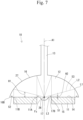
- the ultrasonic wave generation device 10 in the present embodiment differs from that in embodiment 1 in that an inner groove 51 and an outer groove 52 are provided on the inner circumferential side and the outer circumferential side, respectively, relative to the ultrasonic wave generation source 11.
- the same components as those in embodiment 1 are denoted by the same reference characters, and repetitive descriptions thereof are omitted.
- the ultrasonic wave generation device 10 includes: the ultrasonic wave generation source 11 which generates an ultrasonic wave; the ultrasonic wave converging part 12 which converges the ultrasonic wave generated from the ultrasonic wave generation source 11; and the waveguide 13 which allows transmission therethrough of the ultrasonic wave converged by the ultrasonic wave converging part 12.
- the excess portion 21 (not shown) of the adhesive 20, on the inner circumferential side relative to the ultrasonic wave generation source 11, is provided in the region on the outer circumferential side relative to the third imaginary line L3, and the excess portion 21 (not shown) of the adhesive 20, on the outer circumferential side relative to the ultrasonic wave generation source 11, is not provided on the inner circumferential side of the first reflection surface 16 relative to the first imaginary line L1.
- the inner groove 51 is provided on the inner circumferential side relative to the ultrasonic wave generation source 11.
- the inner groove 51 is provided at the center portion of the adhesion surface 18.
- the inner groove 51 is recessed upward from the adhesion surface 18 in the direction orthogonal to the adhesion surface 18.
- the inner groove 51 is provided between the inner circumferential edge 11A of the ultrasonic wave generation source 11 and the outer circumferential edge 17B of the second reflection surface 17.
- the inner groove 51 has an annular shape about the axis A1.
- the inner groove 51 is apart inward from the inner circumferential edge 11A of the ultrasonic wave generation source 11.
- the inner groove 51 is apart outward from the outer circumferential edge 17B of the second reflection surface 17.
- the inner groove 51 is formed on the lower side (the ultrasonic wave generation source 11 side) relative to an imaginary plane 53 formed by all the second imaginary lines L2 between the first imaginary line L1 and the focus Fs.
- the imaginary plane 53 has, in a side view, a right circular conical shape about the axis A1.
- a dimension H1 in the up-down direction parallel to the axis A1 from the adhesion surface 18 to the imaginary plane 53 gradually increases from the center side toward the outer circumferential side of the adhesion surface 18.
- a dimension (depth dimension) H2, in the up-down direction parallel to the axis A1, of the inner groove 51 is smaller than the dimension H1, in the up-down direction, of the imaginary plane 53 at the position of the inner groove 51.
- the outer groove 52 is provided on the outer circumferential side relative to the ultrasonic wave generation source 11.
- the outer groove 52 is provided at the outer edge portion of the adhesion surface 18.
- the outer groove 52 is recessed upward from the adhesion surface 18 in the direction orthogonal to the adhesion surface 18.
- the outer groove 52 has an annular shape about the axis A1.
- the outer groove 52 is apart outward from the outer circumferential edge 11B of the ultrasonic wave generation source 11.
- the outer groove 52 is apart inward from the outer circumferential edge 16B of the first reflection surface 16.
- the inner groove 51 and the outer groove 52 each recessed in the direction intersecting with the adhesion surface 18 are formed on the inner circumferential side and the outer circumferential side, respectively, relative to the ultrasonic wave generation source 11.
- the adhesive 20 sticking out to the inner circumferential side of the ultrasonic wave generation source 11 stays on the ultrasonic wave generation source 11 side owing to the inner groove 51, whereby the adhesive 20 can be made less likely to be adhered to the second reflection surface 17.
- the adhesive 20 sticking out to the outer circumferential side of the ultrasonic wave generation source 11 stays on the ultrasonic wave generation source 11 side owing to the outer groove 52, whereby the adhesive 20 can be made less likely to be adhered to the first reflection surface 16.
- the adhesive 20 is, on the inner circumferential side relative to the ultrasonic wave generation source 11, provided in the region on the outer circumferential side relative to the third imaginary line L3, and the adhesive 20 is, on the outer circumferential side relative to the ultrasonic wave generation source 11, not provided on the inner circumferential side of the first reflection surface 16 relative to the first imaginary line L1. Therefore, the intensity of an ultrasonic wave can be inhibited from decreasing owing to the adhesive 20.
- the inner groove 51 is formed on the ultrasonic wave generation source 11 side relative to the imaginary plane 53 formed by all the second imaginary lines L2 between the first imaginary line L1 and the focus Fs. With this configuration, the inner groove 51 does not overlap with a propagation region for an ultrasonic wave converging from the first reflection surface 16 to the focus Fs. Therefore, the inner groove 51 does not hinder propagation of the ultrasonic wave converging from the first reflection surface 16 to the focus Fs.
- the ultrasonic wave generation system in the present embodiment includes the ultrasonic wave generation device 10 and a power supply device 100.
- the power supply device 100 outputs an electric signal to each of the electrodes in the ultrasonic wave generation device 10 to drive the ultrasonic wave generation device 10.
- the power supply device 100 includes a signal generator 101, a power amplifier 102, and a measuring instrument 103.
- the signal generator 101 generates an arbitrarily-set vibration signal.
- a frequency response analyzer may be used.
- the power amplifier 102 amplifies the signal outputted from the signal generator 101 and applies the amplified signal to the ultrasonic wave generation device 10.
- a known power amplifier may be used.
- the measuring instrument 103 monitors the signal amplified by the power amplifier 102.
- an oscilloscope may be used.
- the power supply device 100 supplies the amplified signal to the ultrasonic wave generation device 10 and monitors applied voltage.
- the ultrasonic wave converging part 12 is formed of a metal and has electrical conductivity, and thus the power supply device 100 is connected to the ultrasonic wave converging part 12 and electrically connected to the ultrasonic wave generation source 11 via the ultrasonic wave converging part 12. Therefore, if the ultrasonic wave converging part 12 is an insulating material, it is desirable that the power supply device 100 and the ultrasonic wave generation source 11 are connected to each other directly or via another electrically-conductive member.
Landscapes
- Health & Medical Sciences (AREA)
- Engineering & Computer Science (AREA)
- Life Sciences & Earth Sciences (AREA)
- Physics & Mathematics (AREA)
- Otolaryngology (AREA)
- Mechanical Engineering (AREA)
- Acoustics & Sound (AREA)
- Veterinary Medicine (AREA)
- Public Health (AREA)
- Animal Behavior & Ethology (AREA)
- General Health & Medical Sciences (AREA)
- Nuclear Medicine, Radiotherapy & Molecular Imaging (AREA)
- Radiology & Medical Imaging (AREA)
- Biomedical Technology (AREA)
- Signal Processing (AREA)
- Pathology (AREA)
- Medical Informatics (AREA)
- Molecular Biology (AREA)
- Surgery (AREA)
- Heart & Thoracic Surgery (AREA)
- Biophysics (AREA)
- Gynecology & Obstetrics (AREA)
- Multimedia (AREA)
- Transducers For Ultrasonic Waves (AREA)
- Surgical Instruments (AREA)
Abstract
Description
- The present invention relates to an ultrasonic wave generation device and an ultrasonic wave generation system.
- Conventionally, ultrasonic wave generation devices used for various purposes such as diagnosis and treatment have been known. For example, the following
Patent Document 1 describes an ultrasonic wave generation device including: an ultrasonic wave generation source which generates an ultrasonic wave; an ultrasonic wave converging part which converges the ultrasonic wave generated by the ultrasonic wave generation source; and a waveguide which allows transmission of the ultrasonic wave converged by the ultrasonic wave converging part. The ultrasonic wave generated by the ultrasonic wave generation source is transmitted to the front end of the waveguide. - Patent Document 1:
WO2006/028249 - In general, an ultrasonic wave generation source of an ultrasonic wave generation device such as one described above is joined to an ultrasonic wave converging part by using an adhesive or the like. In this case, it is desirable that the adhesive is evenly spread on adhesion surfaces of the ultrasonic wave generation source and the ultrasonic wave converging part. However, if the adhesive sticks out from the adhesion surfaces, the intensity of an ultrasonic wave might decrease owing to the adhesive sticking out.
- The present invention has been completed in view of the above circumstance, and an object of the present invention is to provide an ultrasonic wave generation device and an ultrasonic wave generation system that can inhibit the intensity of an ultrasonic wave from decreasing owing to an adhesive.
- An ultrasonic wave generation device of
present invention 1 includes: an ultrasonic wave generation source configured to generate an ultrasonic wave; an ultrasonic wave converging part configured to converge the ultrasonic wave generated from the ultrasonic wave generation source; and a waveguide configured to allow transmission therethrough of the ultrasonic wave converged by the ultrasonic wave converging part. The ultrasonic wave converging part has a first reflection surface located to be opposed to the ultrasonic wave generation source and a second reflection surface located to be opposed to the first reflection surface. The first reflection surface is a curved surface protruding to a side opposite to the ultrasonic wave generation source and reflects the ultrasonic wave that has been generated from the ultrasonic wave generation source, toward the second reflection surface. The second reflection surface is a curved surface protruding to a side opposite to the first reflection surface and reflects the ultrasonic wave that has been reflected by the first reflection surface, toward the waveguide so as to introduce the ultrasonic wave into the waveguide. The ultrasonic wave generation source encloses a circumference, of the second reflection surface, in a radial direction orthogonal to a direction in which the ultrasonic wave generation source and the first reflection surface are opposed to each other. The ultrasonic wave converging part is adhered to the ultrasonic wave generation source by using an adhesive. When a line obtained by projecting an outer circumferential edge of the ultrasonic wave generation source onto the first reflection surface along an advancing direction of the ultrasonic wave generated from the ultrasonic wave generation source is defined as a first imaginary line, and straight lines passing through points on the first imaginary line and a focus for the first reflection surface are defined as second imaginary lines, and a line formed by intersection points between the second reflection surface and all the second imaginary lines is defined as a third imaginary line, the adhesive is, on an inner circumferential side relative to the ultrasonic wave generation source, provided in a region on an outer circumferential side relative to the third imaginary line. - An ultrasonic wave generation device of present invention 2 includes: an ultrasonic wave generation source configured to generate an ultrasonic wave; an ultrasonic wave converging part configured to converge the ultrasonic wave generated from the ultrasonic wave generation source; and a waveguide configured to allow transmission therethrough of the ultrasonic wave converged by the ultrasonic wave converging part. The ultrasonic wave converging part has a first reflection surface located to be opposed to the ultrasonic wave generation source and a second reflection surface located to be opposed to the first reflection surface. The first reflection surface is a curved surface protruding to a side opposite to the ultrasonic wave generation source and reflects the ultrasonic wave that has been generated from the ultrasonic wave generation source, toward the second reflection surface. The second reflection surface is a curved surface protruding to a side opposite to the first reflection surface and reflects the ultrasonic wave that has been reflected by the first reflection surface, toward the waveguide so as to introduce the ultrasonic wave into the waveguide. The ultrasonic wave generation source encloses a circumference, of the second reflection surface, in a radial direction orthogonal to a direction in which the ultrasonic wave generation source and the first reflection surface are opposed to each other. The ultrasonic wave converging part is adhered to the ultrasonic wave generation source by using an adhesive. When a line obtained by projecting an outer circumferential edge of the ultrasonic wave generation source onto the first reflection surface along an advancing direction of the ultrasonic wave generated from the ultrasonic wave generation source is defined as a first imaginary line, the adhesive adhering the ultrasonic wave converging part and the ultrasonic wave generation source to each other is provided also on an outer circumferential side relative to the ultrasonic wave generation source and is not provided on an inner circumferential side of the first reflection surface relative to the first imaginary line.
- According to
present invention 1, the adhesive is not provided in a region, of the second reflection surface, on the inner circumferential side relative to the third imaginary line (a region, of the second reflection surface, in which a particularly intense ultrasonic wave is applied). Therefore, the intensity of an ultrasonic wave can be inhibited from decreasing owing to the adhesive. - According to present invention 2, the adhesive is not provided in a region, of the first reflection surface, on the inner circumferential side relative to a first imaginary plane (a region, of the first reflection surface, in which a particularly intense ultrasonic wave is applied). Therefore, the intensity of an ultrasonic wave can be inhibited from decreasing owing to the adhesive.
-
- [
Fig. 1 ] Diagram for explaining a basic configuration of an ultrasonic wave generation device and showing an image in which an ultrasonic wave generated from an ultrasonic wave generation source advances straight toward a first reflection surface. - [
Fig. 2 ] Diagram for explaining the basic configuration of the ultrasonic wave generation device and showing an image in which the ultrasonic wave reflected by the first reflection surface heads for and is converged to a focus. - [
Fig. 3 ] Schematic cross-sectional view showing an ultrasonic wave generation device inembodiment 1. - [
Fig. 4 ] Bottom view of the ultrasonic wave generation device as seen from below. - [
Fig. 5 ] Schematic cross-sectional view showing an ultrasonic wave generation device in embodiment 2. - [
Fig. 6 ] Schematic cross-sectional view showing an ultrasonic wave generation device inembodiment 3. - [
Fig. 7 ] Schematic cross-sectional view showing an ultrasonic wave generation device in embodiment 4. - [
Fig. 8 ] Diagram showing a configuration of an ultrasonic wave generation system in embodiment 5. - [
Fig. 9 ] Schematic cross-sectional view showing an ultrasonic wave generation device in another embodiment (3). - Preferable modes of the present invention will be described below.
- The ultrasonic wave generation device of
present invention 1 may be configured such that: an accumulation space for the adhesive is provided between an inner circumferential edge of the ultrasonic wave generation source and an outer circumferential edge of the second reflection surface; and the accumulation space extends along an adhesion surface and has a size that allows the adhesive to be accumulated in the accumulation space. With such a configuration, the adhesive sticking out to the inner circumferential side of the ultrasonic wave generation source is accumulated in the accumulation space, whereby the adhesive can be made less likely to be adhered to the second reflection surface than in a case where the accumulation space is not provided. - Alternatively, the ultrasonic wave generation device of
present invention 1 may be configured such that a step surface extending in a direction intersecting with an adhesion surface is formed between an inner circumferential edge of the ultrasonic wave generation source and an outer circumferential edge of the second reflection surface. With such a configuration, the adhesive sticking out to the inner circumferential side of the ultrasonic wave generation source is adhered to the step surface, whereby the adhesive can be made less likely to be adhered to the second reflection surface than in a case where the step surface is not provided. - Alternatively, the ultrasonic wave generation device of
present invention 1 may be configured such that a wall protruding in a direction intersecting with an adhesion surface is provided between an inner circumferential edge of the ultrasonic wave generation source and an outer circumferential edge of the second reflection surface. With such a configuration, the adhesive sticking out from the inner circumferential edge of the ultrasonic wave generation source stays on the ultrasonic wave generation source side owing to the wall, whereby the adhesive can be made less likely to be adhered to the second reflection surface than in a case where the wall is not provided. - Alternatively, the ultrasonic wave generation device of
present invention 1 may be configured such that a groove recessed in a direction intersecting with an adhesion surface is provided between an inner circumferential edge of the ultrasonic wave generation source and an outer circumferential edge of the second reflection surface. With such a configuration, the adhesive sticking out from the inner circumferential edge of the ultrasonic wave generation source stays on the ultrasonic wave generation source side owing to the groove, whereby the adhesive can be made less likely to be adhered to the second reflection surface than in a case where the groove is not provided. - In addition, the ultrasonic wave generation device of
present invention 1 may be configured such that the groove is formed on the ultrasonic wave generation source side relative to an imaginary plane formed between the first imaginary line and the focus by all the second imaginary lines. With such a configuration, the groove does not overlap with a propagation region for an ultrasonic wave converging from the first reflection surface to the focus. Therefore, the groove does not hinder propagation of the ultrasonic wave converging from the first reflection surface to the focus. - The ultrasonic wave generation device of present invention 2 may be configured such that a wall protruding in a direction intersecting with an adhesion surface is provided on the outer circumferential side relative to the outer circumferential edge of the ultrasonic wave generation source. With such a configuration, the adhesive sticking out from the outer circumferential edge of the ultrasonic wave generation source stays on the ultrasonic wave generation source side owing to the wall, whereby the adhesive can be made less likely to be adhered to the first reflection surface than in a case where the wall is not provided.
- The ultrasonic wave generation device of present invention 2 may be configured such that a groove recessed in a direction intersecting with an adhesion surface is provided on the outer circumferential side relative to the outer circumferential edge of the ultrasonic wave generation source. With such a configuration, the adhesive sticking out from the outer circumferential edge of the ultrasonic wave generation source stays on the ultrasonic wave generation source side owing to the groove, whereby the adhesive can be made less likely to be adhered to the first reflection surface than in a case where the groove is not provided.
- <
Embodiment 1> - Hereinafter, an embodiment of the present invention will be described in detail with reference to
Fig. 1 to Fig. 4 . An ultrasonicwave generation device 10 in the present embodiment is used for an ultrasonograph, an ultrasonic treatment device, a cavitation generator, or the like. - Firstly, a basic configuration of the ultrasonic
wave generation device 10 will be described. As shown inFig. 1 , the ultrasonicwave generation device 10 includes an ultrasonicwave generation source 11, an ultrasonicwave converging part 12, and awaveguide 13. The ultrasonicwave generation source 11 generates an ultrasonic wave. The ultrasonicwave converging part 12 converges the ultrasonic wave generated from the ultrasonicwave generation source 11. Thewaveguide 13 allows transmission therethrough of the ultrasonic wave converged by the ultrasonicwave converging part 12. The ultrasonic wave transmitted through thewaveguide 13 is applied to an object. The object is not particularly limited and may be, for example, the inside of a living body. The ultrasonic wave applied to the object is reflected by the object and returned to the inside of thewaveguide 13 as an ultrasonic wave carrying image information about the object. The ultrasonic wave carrying the image information about the object is returned to the ultrasonicwave generation source 11 through thewaveguide 13 and the ultrasonicwave converging part 12. An electric signal based on the ultrasonic wave carrying the image information is received by a signal transmission/reception circuit, and the image information included in the received signal is displayed on a signal display device. As a technology for displaying an image on the basis of such an ultrasonic wave including image information, a known technology employed for an ultrasonograph or the like can be employed. - The ultrasonic
wave generation source 11 is, for example, a piezoelectric element. The ultrasonicwave generation source 11 is formed in the shape of a plate having a predetermined thickness dimension. The ultrasonicwave generation source 11 has a firstmain surface 14 and a secondmain surface 15 on a side opposite to the firstmain surface 14. Electrodes (not shown) are disposed on the firstmain surface 14 and the secondmain surface 15. - The ultrasonic
wave generation source 11 generates an ultrasonic wave when receiving an electric signal from a power supply device 50 (seeFig. 8 ). The ultrasonic wave generated from the ultrasonicwave generation source 11 is a plane wave that advances straight in a direction indicated by an arrow A2 as shown inFig. 1 . The arrow A2 indicates the advancing direction of the ultrasonic wave generated from the ultrasonicwave generation source 11. The arrow A2 is parallel to an axis A1. The ultrasonicwave generation source 11 generates an ultrasonic wave having, for example, a frequency equal to or higher than 30 kHz. Hereinafter, regarding each constituent member, the direction indicated by the arrow A2 inFig. 1 is defined as an upward direction, and the direction opposite thereto is defined as a downward direction. - The ultrasonic
wave converging part 12 is formed of a solid metal (for example, duralumin). The ultrasonicwave converging part 12 has afirst reflection surface 16 and asecond reflection surface 17. Thefirst reflection surface 16 is located to be opposed to the ultrasonicwave generation source 11. A direction in which thefirst reflection surface 16 and the ultrasonicwave generation source 11 are opposed to each other is parallel to the direction in which the axis A1 extends. Thefirst reflection surface 16 is a paraboloid protruding to the upper side (the side opposite to the ultrasonic wave generation source 11) as seen from outside of the ultrasonicwave converging part 12. Thefirst reflection surface 16 has a recessed shape as seen from inside of the ultrasonicwave converging part 12. A center portion of thefirst reflection surface 16 is located above an outercircumferential edge 16B of thefirst reflection surface 16. Thefirst reflection surface 16 is a paraboloid of revolution about the axis A1. - The
second reflection surface 17 is located to be opposed to thefirst reflection surface 16. Thesecond reflection surface 17 is a paraboloid protruding to the lower side (the side opposite to the first reflection surface 16) as seen from outside of the ultrasonicwave converging part 12. Thesecond reflection surface 17 has a recessed shape as seen from inside of the ultrasonicwave converging part 12. A center portion of thesecond reflection surface 17 is located below an outercircumferential edge 17B of thesecond reflection surface 17. Thesecond reflection surface 17 is a paraboloid of revolution about the axis A1. - The
waveguide 13 has the shape of a solid pillar. Thewaveguide 13 extends upward along the axis A1 from the center portion of thefirst reflection surface 16. A cross section, of thewaveguide 13, orthogonal to the axis A1 has a circular shape about the axis A1. A diameter dimension B1, in a direction orthogonal to the axis A1, of thewaveguide 13 is smaller than a diameter dimension B2, in the direction orthogonal to the axis A1, of thesecond reflection surface 17. - The ultrasonic wave generated from the ultrasonic
wave generation source 11 is reflected by thefirst reflection surface 16 and converged to a focus Fs for thefirst reflection surface 16, as shown inFig. 2 . The ultrasonic wave having passed through the focus Fs is reflected by thesecond reflection surface 17 and converged to a focus Fs for thesecond reflection surface 17. The focus Fs for thesecond reflection surface 17 is identical to the focus Fs for thefirst reflection surface 16. The intensity of an ultrasonic wave per unit area of thesecond reflection surface 17 is higher than the intensity of an ultrasonic wave per unit area of thefirst reflection surface 16. The ultrasonic wave reflected by thesecond reflection surface 17 and having passed through the focus Fs is introduced into thewaveguide 13 as a plane wave. The focus Fs is located on the axis A1. - Next, the details of the ultrasonic
wave generation device 10 will be described. The ultrasonicwave generation source 11 encloses a circumference of thesecond reflection surface 17 as shown inFig. 3 andFig. 4 . The ultrasonicwave generation source 11 has an annular shape about the axis A1. An innercircumferential edge 11A of the ultrasonicwave generation source 11 is apart from the outercircumferential edge 17B of thesecond reflection surface 17 outward in a radial direction orthogonal to the axis A1. An outercircumferential edge 11B of the ultrasonicwave generation source 11 is apart from the outercircumferential edge 16B of thefirst reflection surface 16 inward in the radial direction orthogonal to the axis A1. The innercircumferential edge 11A and the outercircumferential edge 11B of the ultrasonicwave generation source 11 are the outer circumferential edge and the inner circumferential edge of the firstmain surface 14, respectively. The outercircumferential edge 16B of thefirst reflection surface 16 and the outercircumferential edge 17B of thesecond reflection surface 17 have circular shapes that are concentric about the axis A1. The area of thesecond reflection surface 17 is smaller than the area of thefirst reflection surface 16. - The ultrasonic
wave converging part 12 has anadhesion surface 18 to be adhered to the ultrasonicwave generation source 11. Theadhesion surface 18 spreads, outward in the radial direction orthogonal to the axis A1, from the outercircumferential edge 17B of thesecond reflection surface 17 to the outercircumferential edge 16B of thefirst reflection surface 16. Theadhesion surface 18 is a flat surface orthogonal to the axis A1. Theadhesion surface 18 has an annular shape so as to enclose the circumference of thesecond reflection surface 17, about the axis A1. - The ultrasonic
wave converging part 12 is adhered to the ultrasonicwave generation source 11 by using an adhesive 20. The adhesive 20 has a characteristic of allowing propagation of an ultrasonic wave. The adhesive 20 includes: an adhesion layer (not shown) disposed between the firstmain surface 14 of the ultrasonicwave generation source 11 and theadhesion surface 18 of the ultrasonicwave converging part 12; and anexcess portion 21 sticking out from the firstmain surface 14. The adhesion layer is thin and spreads over the entirety of the firstmain surface 14. Thus, the ultrasonicwave converging part 12 and the ultrasonicwave generation source 11 can be firmly adhered to each other. In the adhesion layer, air bubbles that are formed are desirably reduced as much as possible, but air bubbles may be contained to some extent. Theexcess portion 21 prevents stress from being concentrated on an outer edge portion of the adhesion layer. Consequently, the ultrasonicwave generation source 11 can be inhibited from peeling from the outer edge portion of the adhesion layer. - The ultrasonic
wave converging part 12 has aninner accumulation space 23 and anouter accumulation space 24 as accumulation spaces for the adhesive 20. Theinner accumulation space 23 and theouter accumulation space 24 extend along theadhesion surface 18. In other words, theinner accumulation space 23 and theouter accumulation space 24 are portions of theadhesion surface 18. - The
inner accumulation space 23 is provided on the inner circumferential side relative to the ultrasonicwave generation source 11. Theinner accumulation space 23 is a portion, of theadhesion surface 18, that is located between the innercircumferential edge 11A of the ultrasonicwave generation source 11 and the outercircumferential edge 17B of thesecond reflection surface 17. Theinner accumulation space 23 has an annular shape about the axis A1 as shown inFig. 4 . Theinner accumulation space 23 encloses the outer circumferential side of thesecond reflection surface 17. A width dimension (a diameter dimension in the direction orthogonal to the axis A1) B3 of theinner accumulation space 23 is fixed over the entire circumference thereof. Theinner accumulation space 23 has a size that allows the correspondingexcess portion 21 of the adhesive 20 to be accumulated therein. - The
outer accumulation space 24 is provided on the outer circumferential side relative to the ultrasonicwave generation source 11. Theouter accumulation space 24 is a portion, of theadhesion surface 18, that is located between the outercircumferential edge 11B of the ultrasonicwave generation source 11 and the outercircumferential edge 16B of thefirst reflection surface 16. Theouter accumulation space 24 has an annular shape about the axis A1 as shown inFig. 4 . Theouter accumulation space 24 encloses the outer circumferential side of the ultrasonicwave generation source 11. A width dimension (a diameter dimension in the direction orthogonal to the axis A1) B4 of theouter accumulation space 24 is fixed over the entire circumference thereof. Theouter accumulation space 24 has a size that allows the correspondingexcess portion 21 of the adhesive 20 to be accumulated therein. - In the
inner accumulation space 23, the correspondingexcess portion 21 of the adhesive 20 stays. Thus, theexcess portion 21 of the adhesive 20 is not provided in aspecific region 26 of thesecond reflection surface 17. Thespecific region 26 of thesecond reflection surface 17 is a region, of thesecond reflection surface 17, in which a particularly intense ultrasonic wave is applied. - In the
outer accumulation space 24, the correspondingexcess portion 21 of the adhesive 20 stays. Thus, theexcess portion 21 of the adhesive 20 is not provided in aspecific region 27 of thefirst reflection surface 16. Thespecific region 27 of thefirst reflection surface 16 is a region, of thefirst reflection surface 16, in which a particularly intense ultrasonic wave is applied. - The
specific region 26 of thesecond reflection surface 17 and thespecific region 27 of thefirst reflection surface 16 will be described by defining a first imaginary line L1, second imaginary lines L2, and a third imaginary line L3. The first imaginary line L1 is an imaginary line on thefirst reflection surface 16. - The first imaginary line L1 is a line obtained by projecting the outer
circumferential edge 11B of the ultrasonicwave generation source 11 onto thefirst reflection surface 16 along the advancing direction of the ultrasonic wave generated from the ultrasonicwave generation source 11. The first imaginary line L1 overlaps with the outercircumferential edge 11B of the ultrasonicwave generation source 11, as seen from below the ultrasonicwave generation device 10. The first imaginary line L1 has a circular shape about the axis A1 on thefirst reflection surface 16. Thespecific region 27 of thefirst reflection surface 16 is a region on the inner circumferential side of thefirst reflection surface 16 relative to the first imaginary line L1. - The second imaginary lines L2 are straight lines passing through points on the first imaginary line L1 and the focus Fs for the
first reflection surface 16. Each of the second imaginary lines L2 extends obliquely downward from the first imaginary line L1 toward the focus Fs as shown inFig. 3 . - The third imaginary line L3 is an imaginary line on the
second reflection surface 17. The third imaginary line L3 is formed by intersection points between thesecond reflection surface 17 and all the second imaginary lines L2. The third imaginary line L3 has a circular shape about the axis A1 on thesecond reflection surface 17. The third imaginary line L3 is located on the inner circumferential side relative to the outercircumferential edge 17B of thesecond reflection surface 17. Thespecific region 26 of thesecond reflection surface 17 is a region, of thesecond reflection surface 17, that is located inward of the third imaginary line L3. - Next, actions and effects of the embodiment configured as described above will be described. The ultrasonic
wave generation device 10 inembodiment 1 includes the ultrasonicwave generation source 11, the ultrasonicwave converging part 12, and thewaveguide 13. The ultrasonicwave generation source 11 generates an ultrasonic wave. The ultrasonicwave converging part 12 converges the ultrasonic wave generated from the ultrasonicwave generation source 11. Thewaveguide 13 allows transmission therethrough of the ultrasonic wave converged by the ultrasonicwave converging part 12. The ultrasonicwave converging part 12 has thefirst reflection surface 16 having a parabolic shape and thesecond reflection surface 17 having a parabolic shape. Thefirst reflection surface 16 is located to be opposed to the ultrasonicwave generation source 11. Thesecond reflection surface 17 is located to be opposed to thefirst reflection surface 16. Thefirst reflection surface 16 reflects the ultrasonic wave that has been generated from the ultrasonicwave generation source 11, toward thesecond reflection surface 17. Thesecond reflection surface 17 reflects the ultrasonic wave that has been reflected by thefirst reflection surface 16, toward thewaveguide 13 so as to introduce the ultrasonic wave into thewaveguide 13. The ultrasonicwave generation source 11 encloses a circumference, of thesecond reflection surface 17, in the radial direction orthogonal to the direction in which the ultrasonicwave generation source 11 and thefirst reflection surface 16 are opposed to each other. The ultrasonicwave converging part 12 is adhered to the ultrasonicwave generation source 11 by using the adhesive 20. When a line obtained by projecting the outercircumferential edge 11B of the ultrasonicwave generation source 11 onto thefirst reflection surface 16 along the advancing direction of the ultrasonic wave generated from the ultrasonicwave generation source 11 is defined as the first imaginary line L1, and straight lines passing through points on the first imaginary line L1 and the focus Fs for thefirst reflection surface 16 are defined as the second imaginary lines L2, and a line formed by the intersection points between thesecond reflection surface 17 and all the second imaginary lines L2 is defined as the third imaginary line L3, the adhesive 20 is, on the inner circumferential side relative to the ultrasonicwave generation source 11, provided in a region on the outer circumferential side relative to the third imaginary line L3. - With this configuration, the adhesive 20 is not provided in a region, of the
second reflection surface 17, on the inner circumferential side relative to the third imaginary line L3 (a region, of thesecond reflection surface 17, in which a particularly intense ultrasonic wave is applied). Therefore, the intensity of an ultrasonic wave can be inhibited from decreasing owing to the adhesive 20. - In addition, the adhesive 20 adhering the ultrasonic
wave converging part 12 and the ultrasonicwave generation source 11 to each other is provided also on the outer circumferential side relative to the ultrasonicwave generation source 11. The adhesive 20 is not provided on the inner circumferential side of thefirst reflection surface 16 relative to the first imaginary line L1. With this configuration, the adhesive 20 is not provided in a region, of thefirst reflection surface 16, in which a particularly intense ultrasonic wave is applied, whereby the intensity of an ultrasonic wave can be inhibited from decreasing owing to the adhesive 20. - In addition, the
inner accumulation space 23 for the adhesive 20 is provided between the innercircumferential edge 11A of the ultrasonicwave generation source 11 and the outercircumferential edge 17B of thesecond reflection surface 17. Theinner accumulation space 23 extends along theadhesion surface 18 and has a size that allows the adhesive 20 to be accumulated in theinner accumulation space 23. With this configuration, the adhesive 20 sticking out to the inner circumferential side of the ultrasonicwave generation source 11 is accumulated in theinner accumulation space 23, whereby the adhesive 20 can be made less likely to be adhered to thesecond reflection surface 17. - In addition, the
outer accumulation space 24 for the adhesive 20 is provided between the outercircumferential edge 11B of the ultrasonicwave generation source 11 and the outercircumferential edge 16B of thefirst reflection surface 16. Theouter accumulation space 24 extends along theadhesion surface 18 and has a size that allows the adhesive 20 to be accumulated in theouter accumulation space 24. With this configuration, the adhesive 20 sticking out from the outer circumferential side of the ultrasonicwave generation source 11 is accumulated in theouter accumulation space 24, whereby the adhesive 20 can be made less likely to be adhered to thefirst reflection surface 16. - Next, an ultrasonic
wave generation device 10 according to embodiment 2 of the present invention will be described with reference toFig. 5 . The ultrasonicwave generation device 10 in the present embodiment differs from that inembodiment 1 in that aninner step surface 31 and anouter step surface 32 are formed on the inner circumferential side and the outer circumferential side relative to the ultrasonicwave generation source 11. The same components as those inembodiment 1 are denoted by the same reference characters, and repetitive descriptions thereof are omitted. - Similar to
embodiment 1, the ultrasonic wave generation device according to the present embodiment includes: the ultrasonicwave generation source 11 which generates an ultrasonic wave; the ultrasonicwave converging part 12 which converges the ultrasonic wave generated from the ultrasonicwave generation source 11; and thewaveguide 13 which allows transmission therethrough of the ultrasonic wave converged by the ultrasonicwave converging part 12. In addition, similar toembodiment 1, the excess portion (not shown) of the adhesive 20, on the inner circumferential side relative to the ultrasonicwave generation source 11, is provided in the region on the outer circumferential side relative to the third imaginary line L3, and the excess portion (not shown) of the adhesive 20, on the outer circumferential side relative to the ultrasonicwave generation source 11, is not provided on the inner circumferential side of thefirst reflection surface 16 relative to the first imaginary line L1. - The
inner step surface 31 is provided on the inner circumferential side relative to the ultrasonicwave generation source 11. Theinner step surface 31 is provided at a center portion of theadhesion surface 18. Theinner step surface 31 is provided between the innercircumferential edge 11A of the ultrasonicwave generation source 11 and the outercircumferential edge 17B of thesecond reflection surface 17. Theinner step surface 31 extends upward from theadhesion surface 18 in a direction orthogonal to theadhesion surface 18. Theinner step surface 31 has a cylindrical shape about the axis A1. The upper edge of theinner step surface 31 is the outercircumferential edge 17B of thesecond reflection surface 17. The lower edge of theinner step surface 31 is the innercircumferential edge 11A of the ultrasonicwave generation source 11. - The
outer step surface 32 is provided on the outer circumferential side relative to the ultrasonicwave generation source 11. Theouter step surface 32 is provided at an outer edge portion of theadhesion surface 18. Theouter step surface 32 extends upward from theadhesion surface 18 in the direction orthogonal to theadhesion surface 18. Theouter step surface 32 has a cylindrical shape about the axis A1. The upper edge of theouter step surface 32 is located inward of the outercircumferential edge 16B of thefirst reflection surface 16. Aspace 33 is provided between the upper edge of theouter step surface 32 and the outercircumferential edge 16B of thefirst reflection surface 16. Thespace 33 has a flat surface orthogonal to the axis A1. The lower edge of theouter step surface 32 is the outercircumferential edge 11B of the ultrasonicwave generation source 11. - As described above, in the present embodiment, the
inner step surface 31 and theouter step surface 32 each extending in a direction intersecting with theadhesion surface 18 are formed on the inner circumferential side and the outer circumferential side, respectively, relative to the ultrasonicwave generation source 11. With this configuration, the adhesive 20 sticking out to the inner circumferential side of the ultrasonicwave generation source 11 is adhered to theinner step surface 31, whereby the adhesive 20 can be made less likely to be adhered to thesecond reflection surface 17. Meanwhile, the adhesive 20 sticking out to the outer circumferential side of the ultrasonicwave generation source 11 is adhered to theouter step surface 32, whereby the adhesive 20 can be made less likely to be adhered to thefirst reflection surface 16. - Consequently, similar to
embodiment 1, the adhesive 20 is, on the inner circumferential side relative to the ultrasonicwave generation source 11, provided in the region on the outer circumferential side relative to the third imaginary line L3, and the adhesive 20 is, on the outer circumferential side relative to the ultrasonicwave generation source 11, not provided on the inner circumferential side of thefirst reflection surface 16 relative to the first imaginary line L1. Therefore, the intensity of an ultrasonic wave can be inhibited from decreasing owing to the adhesive 20. - Next, an ultrasonic
wave generation device 10 according toembodiment 3 of the present invention will be described with reference toFig. 6 . The ultrasonicwave generation device 10 in the present embodiment differs from that inembodiment 1 in that aninner wall 41 and anouter wall 42 are provided on the inner circumferential side and the outer circumferential side, respectively, relative to the ultrasonicwave generation source 11. The same components as those inembodiment 1 are denoted by the same reference characters, and repetitive descriptions thereof are omitted. - Similar to
embodiment 1, the ultrasonic wave generation device according to the present embodiment includes: the ultrasonicwave generation source 11 which generates an ultrasonic wave; the ultrasonicwave converging part 12 which converges the ultrasonic wave generated from the ultrasonicwave generation source 11; and thewaveguide 13 which allows transmission therethrough of the ultrasonic wave converged by the ultrasonicwave converging part 12. In addition, similar toembodiment 1, the excess portion (not shown) of the adhesive 20, on the inner circumferential side relative to the ultrasonicwave generation source 11, is provided in the region on the outer circumferential side relative to the third imaginary line L3, and the excess portion (not shown) of the adhesive 20, on the outer circumferential side relative to the ultrasonicwave generation source 11, is not provided on the inner circumferential side of thefirst reflection surface 16 relative to the first imaginary line L1. - The
inner wall 41 is provided on the inner circumferential side relative to the ultrasonicwave generation source 11. Theinner wall 41 is provided at the center portion of theadhesion surface 18. Theinner wall 41 protrudes downward from theadhesion surface 18 in the direction orthogonal to theadhesion surface 18. Theinner wall 41 is provided between the innercircumferential edge 11A of the ultrasonicwave generation source 11 and the outercircumferential edge 17B of thesecond reflection surface 17. Theinner wall 41 has a cylindrical shape about the axis A1. Theinner wall 41 is apart inward from the innercircumferential edge 11A of the ultrasonicwave generation source 11. Theinner wall 41 is apart outward from the outercircumferential edge 17B of thesecond reflection surface 17. - The
outer wall 42 is provided on the outer circumferential side relative to the ultrasonicwave generation source 11. Theouter wall 42 is provided at the outer edge portion of theadhesion surface 18. Theouter wall 42 protrudes downward from theadhesion surface 18 in the direction orthogonal to theadhesion surface 18. Theouter wall 42 has a cylindrical shape about the axis A1. Theouter wall 42 is apart outward from the outercircumferential edge 11B of the ultrasonicwave generation source 11. Theouter wall 42 is apart inward from the outercircumferential edge 16B of thefirst reflection surface 16. - As described above, in the present embodiment, the
inner wall 41 and theouter wall 42 each protruding in the direction intersecting with theadhesion surface 18 are formed on the inner circumferential side and the outer circumferential side, respectively, relative to the ultrasonicwave generation source 11. With this configuration, the adhesive 20 sticking out to the inner circumferential side of the ultrasonicwave generation source 11 stays on the ultrasonicwave generation source 11 side owing to theinner wall 41, whereby the adhesive 20 can be made less likely to be adhered to thesecond reflection surface 17. Meanwhile, the adhesive 20 sticking out to the outer circumferential side of the ultrasonicwave generation source 11 stays on the ultrasonicwave generation source 11 side owing to theouter wall 42, whereby the adhesive 20 can be made less likely to be adhered to thefirst reflection surface 16. - Consequently, similar to
embodiment 1, the adhesive 20 is, on the inner circumferential side relative to the ultrasonicwave generation source 11, provided in the region on the outer circumferential side relative to the third imaginary line L3, and the adhesive 20 is, on the outer circumferential side relative to the ultrasonicwave generation source 11, not provided on the inner circumferential side of thefirst reflection surface 16 relative to the first imaginary line L1. Therefore, the intensity of an ultrasonic wave can be inhibited from decreasing owing to the adhesive 20. - Next, an ultrasonic
wave generation device 10 according to embodiment 4 of the present invention will be described with reference toFig. 7 . The ultrasonicwave generation device 10 in the present embodiment differs from that inembodiment 1 in that aninner groove 51 and anouter groove 52 are provided on the inner circumferential side and the outer circumferential side, respectively, relative to the ultrasonicwave generation source 11. The same components as those inembodiment 1 are denoted by the same reference characters, and repetitive descriptions thereof are omitted. - Similar to
embodiment 1, the ultrasonicwave generation device 10 according to the present embodiment includes: the ultrasonicwave generation source 11 which generates an ultrasonic wave; the ultrasonicwave converging part 12 which converges the ultrasonic wave generated from the ultrasonicwave generation source 11; and thewaveguide 13 which allows transmission therethrough of the ultrasonic wave converged by the ultrasonicwave converging part 12. In addition, similar toembodiment 1, the excess portion 21 (not shown) of the adhesive 20, on the inner circumferential side relative to the ultrasonicwave generation source 11, is provided in the region on the outer circumferential side relative to the third imaginary line L3, and the excess portion 21 (not shown) of the adhesive 20, on the outer circumferential side relative to the ultrasonicwave generation source 11, is not provided on the inner circumferential side of thefirst reflection surface 16 relative to the first imaginary line L1. - The
inner groove 51 is provided on the inner circumferential side relative to the ultrasonicwave generation source 11. Theinner groove 51 is provided at the center portion of theadhesion surface 18. Theinner groove 51 is recessed upward from theadhesion surface 18 in the direction orthogonal to theadhesion surface 18. Theinner groove 51 is provided between the innercircumferential edge 11A of the ultrasonicwave generation source 11 and the outercircumferential edge 17B of thesecond reflection surface 17. Theinner groove 51 has an annular shape about the axis A1. Theinner groove 51 is apart inward from the innercircumferential edge 11A of the ultrasonicwave generation source 11. Theinner groove 51 is apart outward from the outercircumferential edge 17B of thesecond reflection surface 17. - The
inner groove 51 is formed on the lower side (the ultrasonicwave generation source 11 side) relative to animaginary plane 53 formed by all the second imaginary lines L2 between the first imaginary line L1 and the focus Fs. Theimaginary plane 53 has, in a side view, a right circular conical shape about the axis A1. A dimension H1 in the up-down direction parallel to the axis A1 from theadhesion surface 18 to theimaginary plane 53 gradually increases from the center side toward the outer circumferential side of theadhesion surface 18. A dimension (depth dimension) H2, in the up-down direction parallel to the axis A1, of theinner groove 51 is smaller than the dimension H1, in the up-down direction, of theimaginary plane 53 at the position of theinner groove 51. - The
outer groove 52 is provided on the outer circumferential side relative to the ultrasonicwave generation source 11. Theouter groove 52 is provided at the outer edge portion of theadhesion surface 18. Theouter groove 52 is recessed upward from theadhesion surface 18 in the direction orthogonal to theadhesion surface 18. Theouter groove 52 has an annular shape about the axis A1. Theouter groove 52 is apart outward from the outercircumferential edge 11B of the ultrasonicwave generation source 11. Theouter groove 52 is apart inward from the outercircumferential edge 16B of thefirst reflection surface 16. - As described above, in the present embodiment, similar to
embodiment 1, theinner groove 51 and theouter groove 52 each recessed in the direction intersecting with theadhesion surface 18 are formed on the inner circumferential side and the outer circumferential side, respectively, relative to the ultrasonicwave generation source 11. With this configuration, the adhesive 20 sticking out to the inner circumferential side of the ultrasonicwave generation source 11 stays on the ultrasonicwave generation source 11 side owing to theinner groove 51, whereby the adhesive 20 can be made less likely to be adhered to thesecond reflection surface 17. Meanwhile, the adhesive 20 sticking out to the outer circumferential side of the ultrasonicwave generation source 11 stays on the ultrasonicwave generation source 11 side owing to theouter groove 52, whereby the adhesive 20 can be made less likely to be adhered to thefirst reflection surface 16. - Consequently, similar to
embodiment 1, the adhesive 20 is, on the inner circumferential side relative to the ultrasonicwave generation source 11, provided in the region on the outer circumferential side relative to the third imaginary line L3, and the adhesive 20 is, on the outer circumferential side relative to the ultrasonicwave generation source 11, not provided on the inner circumferential side of thefirst reflection surface 16 relative to the first imaginary line L1. Therefore, the intensity of an ultrasonic wave can be inhibited from decreasing owing to the adhesive 20. - The
inner groove 51 is formed on the ultrasonicwave generation source 11 side relative to theimaginary plane 53 formed by all the second imaginary lines L2 between the first imaginary line L1 and the focus Fs. With this configuration, theinner groove 51 does not overlap with a propagation region for an ultrasonic wave converging from thefirst reflection surface 16 to the focus Fs. Therefore, theinner groove 51 does not hinder propagation of the ultrasonic wave converging from thefirst reflection surface 16 to the focus Fs. - Next, an ultrasonic wave generation system according to embodiment 5 of the present invention will be described with reference to
Fig. 8 . The same components as those in the above embodiments are denoted by the same reference characters, and repetitive descriptions thereof are omitted. The ultrasonic wave generation system in the present embodiment includes the ultrasonicwave generation device 10 and apower supply device 100. Thepower supply device 100 outputs an electric signal to each of the electrodes in the ultrasonicwave generation device 10 to drive the ultrasonicwave generation device 10. - The
power supply device 100 includes asignal generator 101, apower amplifier 102, and a measuringinstrument 103. Thesignal generator 101 generates an arbitrarily-set vibration signal. As thesignal generator 101, for example, a frequency response analyzer may be used. Thepower amplifier 102 amplifies the signal outputted from thesignal generator 101 and applies the amplified signal to the ultrasonicwave generation device 10. As thepower amplifier 102, for example, a known power amplifier may be used. The measuringinstrument 103 monitors the signal amplified by thepower amplifier 102. As the measuringinstrument 103, for example, an oscilloscope may be used. Thepower supply device 100 supplies the amplified signal to the ultrasonicwave generation device 10 and monitors applied voltage. - In the present embodiment, the ultrasonic
wave converging part 12 is formed of a metal and has electrical conductivity, and thus thepower supply device 100 is connected to the ultrasonicwave converging part 12 and electrically connected to the ultrasonicwave generation source 11 via the ultrasonicwave converging part 12. Therefore, if the ultrasonicwave converging part 12 is an insulating material, it is desirable that thepower supply device 100 and the ultrasonicwave generation source 11 are connected to each other directly or via another electrically-conductive member. - Embodiments of the present invention are not limited to those described in the above explanations and with reference to the drawings, and, for example, the following embodiments are also included in the technical scope of the present invention.
- (1) In the
above embodiment 1, the ultrasonicwave generation device 10 includes theinner accumulation space 23 and theouter accumulation space 24. Without limitation thereto, the ultrasonic wave generation device may include only one of the inner accumulation space and the outer accumulation space. - (2) In the above embodiment 2, the
inner step surface 31 and theouter step surface 32 are orthogonal to theadhesion surface 18. Without limitation thereto, the step surfaces may be tilted with respect to the adhesion surface. - (3) In the above embodiment 2, the ultrasonic
wave generation device 10 includes theinner step surface 31 and theouter step surface 32. The ultrasonicwave generation device 10 may be provided with, in addition to these step surfaces, aspace 60 on the inner circumferential side relative to theinner step surface 31 as shown inFig. 9 . Thespace 60 may be formed as a flat surface orthogonal to the axis A1. - (4) In each of the above embodiments, the
excess portion 21 of the adhesive 20 may be provided on the upper side relative to the outercircumferential edge 16B of thefirst reflection surface 16 and may be, if the amount thereof is small, provided on the inner circumferential side of thefirst reflection surface 16 relative to the first imaginary line L1. - (5) In each of the above embodiments, the
first reflection surface 16 and thesecond reflection surface 17 are paraboloids. Without limitation thereto, both or one of the first reflection surface and the second reflection surface does not have to be a paraboloid in an exact sense and may have a shape with which the reflection surface can be regarded as an approximate paraboloid. In other words, both or one of the first reflection surface and the second reflection surface only has to be a surface that is curved such that the ultrasonic wave generated from the ultrasonic wave generation source reaches the waveguide via the first reflection surface and the second reflection surface. The first reflection surface and the second reflection surface may be composed of a large number of minute flat surfaces. - (6) In each of the above embodiments, the ultrasonic
wave generation source 11 is a piezoelectric element formed of piezoelectric ceramic. Without limitation thereto, another piezoelectric material can be used for the ultrasonic wave generation source. The ultrasonic wave generation source may be, for example, a piezoelectric laminated body or the like formed of piezoelectric ceramic. - (7) In the above embodiments, the
inner accumulation space 23 and theouter accumulation space 24, theinner step surface 31 and theouter step surface 32, theinner wall 41 and theouter wall 42, or theinner groove 51 and theouter groove 52 are respectively provided on the inner circumferential side and the outer circumferential side relative to the ultrasonicwave generation source 11. Without limitation thereto, components of different embodiments may be provided on the inner circumferential side and the outer circumferential side relative to the ultrasonic wave generation source. For example, a wall may be provided on the inner circumferential side and a groove may be provided on the outer circumferential side relative to the ultrasonic wave generation source. - (8) In each of the above embodiments, the
waveguide 13 and the ultrasonicwave converging part 12 are each solid. However, the waveguide and the ultrasonic wave converging part are not limited to solid ones and may have, for example, through-holes or closed spaces formed therein. -
- Fs: focus
- L1: first imaginary line
- L2: second imaginary line
- L3: third imaginary line
- 10: ultrasonic wave generation device
- 11: ultrasonic wave generation source
- 11A: inner circumferential edge of ultrasonic wave generation source
- 11B: outer circumferential edge of ultrasonic wave generation source
- 12: ultrasonic wave converging part
- 13: waveguide
- 16: first reflection surface
- 17: second reflection surface
- 17B: outer circumferential edge of second reflection surface
- 18: adhesion surface
- 20: adhesive
- 23: inner accumulation space (accumulation space)
- 31: inner step surface (step surface)
- 41: inner wall (wall)
- 42: outer wall (wall)
- 51: inner groove (groove)
- 52: outer groove (groove)
- 53: imaginary plane
- 100: power supply device
Claims (10)
- An ultrasonic wave generation device comprising:an ultrasonic wave generation source configured to generate an ultrasonic wave;an ultrasonic wave converging part configured to converge the ultrasonic wave generated from the ultrasonic wave generation source; anda waveguide configured to allow transmission therethrough of the ultrasonic wave converged by the ultrasonic wave converging part,the ultrasonic wave converging part having a first reflection surface located to be opposed to the ultrasonic wave generation source and a second reflection surface located to be opposed to the first reflection surface,the first reflection surface being a curved surface protruding to a side opposite to the ultrasonic wave generation source and configured to reflect the ultrasonic wave that has been generated from the ultrasonic wave generation source, toward the second reflection surface,the second reflection surface being a curved surface protruding to a side opposite to the first reflection surface and configured to reflect the ultrasonic wave that has been reflected by the first reflection surface, toward the waveguide so as to introduce the ultrasonic wave into the waveguide, andthe ultrasonic wave generation source enclosing a circumference, of the second reflection surface, in a radial direction orthogonal to a direction in which the ultrasonic wave generation source and the first reflection surface are opposed to each other,whereinthe ultrasonic wave converging part is adhered to the ultrasonic wave generation source by using an adhesive, and,when a line obtained by projecting an outer circumferential edge of the ultrasonic wave generation source onto the first reflection surface along an advancing direction of the ultrasonic wave generated from the ultrasonic wave generation source is defined as a first imaginary line, and straight lines passing through points on the first imaginary line and a focus for the first reflection surface are defined as second imaginary lines, and a line formed by intersection points between the second reflection surface and all the second imaginary lines is defined as a third imaginary line,the adhesive is, on an inner circumferential side relative to the ultrasonic wave generation source, provided in a region on an outer circumferential side relative to the third imaginary line.
- An ultrasonic wave generation device comprising:an ultrasonic wave generation source configured to generate an ultrasonic wave;an ultrasonic wave converging part configured to converge the ultrasonic wave generated from the ultrasonic wave generation source; anda waveguide configured to allow transmission therethrough of the ultrasonic wave converged by the ultrasonic wave converging part,the ultrasonic wave converging part having a first reflection surface located to be opposed to the ultrasonic wave generation source and a second reflection surface located to be opposed to the first reflection surface,the first reflection surface being a curved surface protruding to a side opposite to the ultrasonic wave generation source and configured to reflect the ultrasonic wave that has been generated from the ultrasonic wave generation source, toward the second reflection surface,the second reflection surface being a curved surface protruding to a side opposite to the first reflection surface and configured to reflect the ultrasonic wave that has been reflected by the first reflection surface, toward the waveguide so as to introduce the ultrasonic wave into the waveguide, andthe ultrasonic wave generation source enclosing a circumference, of the second reflection surface, in a radial direction orthogonal to a direction in which the ultrasonic wave generation source and the first reflection surface are opposed to each other,whereinthe ultrasonic wave converging part is adhered to the ultrasonic wave generation source by using an adhesive, and,when a line obtained by projecting an outer circumferential edge of the ultrasonic wave generation source onto the first reflection surface along an advancing direction of the ultrasonic wave generated from the ultrasonic wave generation source is defined as a first imaginary line,the adhesive adhering the ultrasonic wave converging part and the ultrasonic wave generation source to each other is provided also on an outer circumferential side relative to the ultrasonic wave generation source and is not provided on an inner circumferential side of the first reflection surface relative to the first imaginary line.
- The ultrasonic wave generation device according to claim 1, whereinan accumulation space for the adhesive is provided between an inner circumferential edge of the ultrasonic wave generation source and an outer circumferential edge of the second reflection surface, andthe accumulation space extends along an adhesion surface and has a size that allows the adhesive to be accumulated in the accumulation space.
- The ultrasonic wave generation device according to claim 1, wherein
a step surface extending in a direction intersecting with an adhesion surface is formed between an inner circumferential edge of the ultrasonic wave generation source and an outer circumferential edge of the second reflection surface. - The ultrasonic wave generation device according to claim 1, wherein
a wall protruding in a direction intersecting with an adhesion surface is provided between an inner circumferential edge of the ultrasonic wave generation source and an outer circumferential edge of the second reflection surface. - The ultrasonic wave generation device according to claim 1, wherein
a groove recessed in a direction intersecting with an adhesion surface is provided between an inner circumferential edge of the ultrasonic wave generation source and an outer circumferential edge of the second reflection surface. - The ultrasonic wave generation device according to claim 6, wherein
the groove is formed on the ultrasonic wave generation source side relative to an imaginary plane formed by all the second imaginary lines between the first imaginary line and the focus. - The ultrasonic wave generation device according to claim 2, wherein
a wall protruding in a direction intersecting with an adhesion surface is provided on the outer circumferential side relative to the outer circumferential edge of the ultrasonic wave generation source. - The ultrasonic wave generation device according to claim 2, wherein
a groove recessed in a direction intersecting with an adhesion surface is provided on the outer circumferential side relative to the outer circumferential edge of the ultrasonic wave generation source. - An ultrasonic wave generation system comprising:the ultrasonic wave generation device according to any one of claims 1 to 9; anda power supply device configured to output an electric signal to the ultrasonic wave generation device.
Applications Claiming Priority (2)
| Application Number | Priority Date | Filing Date | Title |
|---|---|---|---|
| JP2021175394 | 2021-10-27 | ||
| PCT/JP2022/039607 WO2023074650A1 (en) | 2021-10-27 | 2022-10-25 | Ultrasonic wave generating device and ultrasonic wave generating system |
Publications (2)
| Publication Number | Publication Date |
|---|---|
| EP4425959A1 true EP4425959A1 (en) | 2024-09-04 |
| EP4425959A4 EP4425959A4 (en) | 2025-10-15 |
Family
ID=86157802
Family Applications (1)
| Application Number | Title | Priority Date | Filing Date |
|---|---|---|---|
| EP22886977.2A Pending EP4425959A4 (en) | 2021-10-27 | 2022-10-25 | ULTRASONIC WAVE GENERATION DEVICE AND ULTRASONIC WAVE GENERATION SYSTEM |
Country Status (6)
| Country | Link |
|---|---|
| US (1) | US20250235895A1 (en) |
| EP (1) | EP4425959A4 (en) |
| JP (1) | JP7488419B2 (en) |
| KR (1) | KR102927906B1 (en) |
| CN (1) | CN118044224A (en) |
| WO (1) | WO2023074650A1 (en) |
Families Citing this family (2)
| Publication number | Priority date | Publication date | Assignee | Title |
|---|---|---|---|---|
| KR102927906B1 (en) * | 2021-10-27 | 2026-02-13 | 니혼도꾸슈도교 가부시키가이샤 | Ultrasonic generator and ultrasonic generator system |
| JP2024165448A (en) * | 2023-05-17 | 2024-11-28 | 日本特殊陶業株式会社 | Ultrasonic generator |
Family Cites Families (5)
| Publication number | Priority date | Publication date | Assignee | Title |
|---|---|---|---|---|
| JPH053598A (en) * | 1991-06-18 | 1993-01-08 | Toshiba Corp | Ultrasonic probe manufacturing method |
| WO2006028249A1 (en) | 2004-09-10 | 2006-03-16 | Microsonic Co., Ltd. | Ultrasonic probe, ultrasonograph, and ultrasonography |
| JP7265977B2 (en) * | 2019-12-06 | 2023-04-27 | 日本特殊陶業株式会社 | ultrasonic generator |
| JP6774697B1 (en) * | 2020-05-25 | 2020-10-28 | 株式会社Mu研究所 | Ultrasonic irradiator |
| KR102927906B1 (en) * | 2021-10-27 | 2026-02-13 | 니혼도꾸슈도교 가부시키가이샤 | Ultrasonic generator and ultrasonic generator system |
-
2022
- 2022-10-25 KR KR1020247011057A patent/KR102927906B1/en active Active
- 2022-10-25 EP EP22886977.2A patent/EP4425959A4/en active Pending
- 2022-10-25 CN CN202280066602.XA patent/CN118044224A/en active Pending
- 2022-10-25 US US18/698,061 patent/US20250235895A1/en active Pending
- 2022-10-25 JP JP2023517341A patent/JP7488419B2/en active Active
- 2022-10-25 WO PCT/JP2022/039607 patent/WO2023074650A1/en not_active Ceased
Also Published As
| Publication number | Publication date |
|---|---|
| TW202327521A (en) | 2023-07-16 |
| JPWO2023074650A1 (en) | 2023-05-04 |
| KR20240056568A (en) | 2024-04-30 |
| CN118044224A (en) | 2024-05-14 |
| EP4425959A4 (en) | 2025-10-15 |
| JP7488419B2 (en) | 2024-05-21 |
| US20250235895A1 (en) | 2025-07-24 |
| WO2023074650A1 (en) | 2023-05-04 |
| KR102927906B1 (en) | 2026-02-13 |
Similar Documents
| Publication | Publication Date | Title |
|---|---|---|
| US20250235895A1 (en) | Ultrasonic wave generation device and ultrasonic wave generation system | |
| EP3135190A1 (en) | Acoustic wave probe, acoustic wave transducer unit, and object information acquisition apparatus | |
| US11576653B2 (en) | Ultrasonic generator | |
| JP2015503283A (en) | Backing member, ultrasonic probe, and ultrasonic image display device | |
| EP3023778B1 (en) | Capacitive transducer and sample information acquisition apparatus | |
| EP2530953A1 (en) | Ultrasonic vibration device | |
| JP2001245861A (en) | Pulse detection device and manufacturing method thereof | |
| US20250033085A1 (en) | Ultrasonic wave generation device and ultrasonic wave generation system | |
| JP5406374B2 (en) | Ultrasonic probe and ultrasonic diagnostic apparatus using the same | |
| US8091428B2 (en) | Ultrasonic probe and ultrasonic diagnostic apparatus | |
| JP7137632B2 (en) | Ultrasonic emitting instruments and ultrasonic devices | |
| KR20110003057A (en) | Ultrasonic Probes and Ultrasonic Diagnostics | |
| TWI923850B (en) | Ultrasonic generating device and ultrasonic generating system | |
| EP2565642B1 (en) | L-mode guided wave sensor | |
| JP3212734U (en) | Ultrasonic probe | |
| JP2016101317A (en) | Acoustic probe | |
| JPH0833097A (en) | Piezoelectric element | |
| US20240138812A1 (en) | Ultrasonic wave generation device | |
| US20170119346A1 (en) | Ultrasonic device, ultrasonic probe, electronic apparatus, and ultrasonic imaging apparatus | |
| JPH09271097A (en) | Ultrasonic probe | |
| JP2025023389A (en) | Ultrasonic generator | |
| JP2021197653A (en) | Ultrasonic sensor | |
| JP7288562B1 (en) | Ultrasonic transducer array and ultrasonic phased array sensor | |
| JPH071920Y2 (en) | Ultrasonic transducer | |
| EP4611395A1 (en) | Ultrasonic wave generating device |
Legal Events
| Date | Code | Title | Description |
|---|---|---|---|
| STAA | Information on the status of an ep patent application or granted ep patent |
Free format text: STATUS: THE INTERNATIONAL PUBLICATION HAS BEEN MADE |
|
| PUAI | Public reference made under article 153(3) epc to a published international application that has entered the european phase |
Free format text: ORIGINAL CODE: 0009012 |
|
| STAA | Information on the status of an ep patent application or granted ep patent |
Free format text: STATUS: REQUEST FOR EXAMINATION WAS MADE |
|
| 17P | Request for examination filed |
Effective date: 20240527 |
|
| AK | Designated contracting states |
Kind code of ref document: A1 Designated state(s): AL AT BE BG CH CY CZ DE DK EE ES FI FR GB GR HR HU IE IS IT LI LT LU LV MC ME MK MT NL NO PL PT RO RS SE SI SK SM TR |
|
| DAV | Request for validation of the european patent (deleted) | ||
| DAX | Request for extension of the european patent (deleted) | ||
| REG | Reference to a national code |
Ref country code: DE Ref legal event code: R079 Free format text: PREVIOUS MAIN CLASS: H04R0001340000 Ipc: B06B0003040000 |
|
| A4 | Supplementary search report drawn up and despatched |
Effective date: 20250912 |
|
| RIC1 | Information provided on ipc code assigned before grant |
Ipc: B06B 3/04 20060101AFI20250908BHEP Ipc: G10K 11/28 20060101ALI20250908BHEP Ipc: A61B 8/00 20060101ALI20250908BHEP Ipc: A61N 7/00 20060101ALN20250908BHEP |