EP4425908A1 - Information display method and electronic device - Google Patents
Information display method and electronic device Download PDFInfo
- Publication number
- EP4425908A1 EP4425908A1 EP22885804.9A EP22885804A EP4425908A1 EP 4425908 A1 EP4425908 A1 EP 4425908A1 EP 22885804 A EP22885804 A EP 22885804A EP 4425908 A1 EP4425908 A1 EP 4425908A1
- Authority
- EP
- European Patent Office
- Prior art keywords
- lug boss
- hole
- camera
- electronic device
- base
- Prior art date
- Legal status (The legal status is an assumption and is not a legal conclusion. Google has not performed a legal analysis and makes no representation as to the accuracy of the status listed.)
- Granted
Links
Images


Classifications
-
- H—ELECTRICITY
- H04—ELECTRIC COMMUNICATION TECHNIQUE
- H04M—TELEPHONIC COMMUNICATION
- H04M1/00—Substation equipment, e.g. for use by subscribers
- H04M1/02—Constructional features of telephone sets
- H04M1/0202—Portable telephone sets, e.g. cordless phones, mobile phones or bar type handsets
- H04M1/026—Details of the structure or mounting of specific components
- H04M1/0264—Details of the structure or mounting of specific components for a camera module assembly
-
- G—PHYSICS
- G03—PHOTOGRAPHY; CINEMATOGRAPHY; ANALOGOUS TECHNIQUES USING WAVES OTHER THAN OPTICAL WAVES; ELECTROGRAPHY; HOLOGRAPHY
- G03B—APPARATUS OR ARRANGEMENTS FOR TAKING PHOTOGRAPHS OR FOR PROJECTING OR VIEWING THEM; APPARATUS OR ARRANGEMENTS EMPLOYING ANALOGOUS TECHNIQUES USING WAVES OTHER THAN OPTICAL WAVES; ACCESSORIES THEREFOR
- G03B17/00—Details of cameras or camera bodies; Accessories therefor
- G03B17/02—Bodies
-
- G—PHYSICS
- G03—PHOTOGRAPHY; CINEMATOGRAPHY; ANALOGOUS TECHNIQUES USING WAVES OTHER THAN OPTICAL WAVES; ELECTROGRAPHY; HOLOGRAPHY
- G03B—APPARATUS OR ARRANGEMENTS FOR TAKING PHOTOGRAPHS OR FOR PROJECTING OR VIEWING THEM; APPARATUS OR ARRANGEMENTS EMPLOYING ANALOGOUS TECHNIQUES USING WAVES OTHER THAN OPTICAL WAVES; ACCESSORIES THEREFOR
- G03B17/00—Details of cameras or camera bodies; Accessories therefor
- G03B17/56—Accessories
- G03B17/565—Optical accessories, e.g. converters for close-up photography, tele-convertors, wide-angle convertors
-
- H—ELECTRICITY
- H04—ELECTRIC COMMUNICATION TECHNIQUE
- H04M—TELEPHONIC COMMUNICATION
- H04M1/00—Substation equipment, e.g. for use by subscribers
- H04M1/02—Constructional features of telephone sets
- H04M1/0202—Portable telephone sets, e.g. cordless phones, mobile phones or bar type handsets
- H04M1/0279—Improving the user comfort or ergonomics
- H04M1/0283—Improving the user comfort or ergonomics for providing a decorative aspect, e.g. customization of casings, exchangeable faceplate
-
- H—ELECTRICITY
- H04—ELECTRIC COMMUNICATION TECHNIQUE
- H04N—PICTORIAL COMMUNICATION, e.g. TELEVISION
- H04N23/00—Cameras or camera modules comprising electronic image sensors; Control thereof
- H04N23/50—Constructional details
- H04N23/51—Housings
-
- H—ELECTRICITY
- H04—ELECTRIC COMMUNICATION TECHNIQUE
- H04N—PICTORIAL COMMUNICATION, e.g. TELEVISION
- H04N23/00—Cameras or camera modules comprising electronic image sensors; Control thereof
- H04N23/50—Constructional details
- H04N23/53—Constructional details of electronic viewfinders, e.g. rotatable or detachable
-
- H—ELECTRICITY
- H04—ELECTRIC COMMUNICATION TECHNIQUE
- H04N—PICTORIAL COMMUNICATION, e.g. TELEVISION
- H04N23/00—Cameras or camera modules comprising electronic image sensors; Control thereof
- H04N23/50—Constructional details
- H04N23/55—Optical parts specially adapted for electronic image sensors; Mounting thereof
Definitions
- This application pertains to the communication field, and specifically relates to an electronic device.
- the camera function is a fundamental feature of electronic devices, which can satisfy user needs for shooting.
- the camera function is implemented through the camera module of electronic devices.
- This application aims to provide an electronic device so as to optimize an internal space of the electronic device and facilitate the thinning of the electronic device.
- an electronic device including:
- the skirt includes a plurality of strip edges, where the plurality of strip edges are spaced apart from each other, and two adjacent strip edges have the avoidance space.
- the electronic device further includes a cover plate.
- the cover plate includes a plate body and a mounting lug boss connected to the plate body, a second through hole is provided in the mounting lug boss, and the first through hole is in communication with the second through hole; and the decorative ring covers the mounting lug boss, and the mounting lug boss is sealingly connected to the top corner of the base through the avoidance space.
- cover plate further includes a plurality of mounting notches provided between the mounting lug boss and the plate body, and the skirt is inserted into the mounting notches.
- the mounting lug boss is located on a side of the plate body close to the decorative ring; or a surface of the mounting lug boss close to the decorative ring is flush with a surface of the plate body close to the decorative ring.
- the base of the camera is of a rectangular body structure, four top corners of the base are each provided with a notch, and notch bases of the notches are connected to the bottom of the mounting lug boss.
- the electronic device further includes a motherboard support, where the motherboard support includes a support body and a sealing lug boss connected to the support body, a third through hole is provided in the sealing lug boss, and the third through hole is in communication with the second through hole; and the sealing lug boss is sandwiched between the mounting lug boss and each of the top corners of the base of the camera through a sealing member, and the notch bases of the notches are connected to the bottom of the sealing lug boss.
- sealing member includes sealing foam.
- the electronic device further includes a battery cover, where the battery cover includes a cover body and a decorative hole that passes through the cover body; and the cover plate further includes a cover plate skirt extending outwardly from an edge of the plate body, the cover plate skirt is connected to an edge of the decorative hole, and the decorative ring is located in the decorative hole.
- the electronic device further includes a lens.
- the decorative ring further includes a supporting table extending inwardly from the frame body to form the first through hole, and the supporting table carries the lens to allow the lens to cover a viewing angle of the camera lens.
- the avoidance space is designed on the skirt of the decorative ring, and the top corners of the base of the camera are at least partially disposed in the avoidance space, so that a fitting height between the camera and the decorative ring can be reduced, and an internal space of the electronic device can be optimized, thereby facilitating the thinning of the electronic device.
- first and second in the specification and claims of this application may expressly or impliedly include one or more of such features.
- plural means two or more, unless otherwise specified.
- and/or in the specification and claims represents at least one of connected objects, and the character “/” generally indicates that the contextually associated objects have an “or” relationship.
- the terms “mounting”, “joint”, and “connection” should be understood in a broad sense. For example, they may refer to a fixed connection, a detachable connection, or an integral connection; may refer to a mechanical connection or an electrical connection; and may refer to a direct connection, an indirect connection via an intermediate medium, or an internal communication between two elements.
- mounting may refer to a fixed connection, a detachable connection, or an integral connection; may refer to a mechanical connection or an electrical connection; and may refer to a direct connection, an indirect connection via an intermediate medium, or an internal communication between two elements.
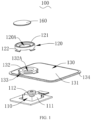
- An electronic device 100 in some embodiments of this application is described below with reference to FIG. 1 and FIG. 2 , and includes:
- the avoidance space 123 is designed on the skirt 122 of the decorative ring 120, and the top corners of the base 111 of the camera 110 are at least partially disposed in the avoidance space 123, so that a fitting height between the camera 110 and the decorative ring 120 can be reduced, and an internal space of the electronic device 100 can be optimized, thereby facilitating the thinning of the electronic device 100.
- the camera 110 includes the base 111 for fixing the camera lens 112, and the top of the base 111 is connected to the bottom of the camera 112.
- the base 111 and the camera lens 112 may be fixedly connected.
- the camera lens 112 is not able to swing relative to the base 111, and a viewing angle of the camera lens 112 is fixed in a case that the base 111 is fixed.
- the base 111 and the camera lens 112 may be movably connected. In this case, the camera lens 112 is able to swing relative to the base 111, and a viewing direction of the camera lens 112 can be adjusted in a case that the base 111 is fixed.
- the first through hole 120A is provided in the frame body 121 of the decorative ring 120, at least part of the camera lens 112 is located in the first through hole 120A, and the camera lens 112 takes a view of the environment outside the electronic device 100 through the first through hole 120A.
- the frame body 121 may be an annular frame body.
- the frame body 121 of the decorative ring 120 surrounds the camera lens 112 on a housing of the electronic device 100 so as to protect the camera lens 112 and improve aesthetics of the electronic device.
- the base 111 may be a triangular prism structure, that is, the base 111 has three top corners. In this case, there are at least three avoidance spaces 123 on the skirt 122.
- the base 111 may be a quadrangular prism structure, that is, the base 111 has four top corners. In this case, there are at least four avoidance spaces 123 on the skirt 122.
- the base 111 may be a hexagonal prism structure, that is, the base 111 has six top corners. In this case, there are at least six avoidance spaces 123 on the skirt 122.
- the base 111 of the camera 110 is a rectangular frame structure (that is, a positive quadrangular prism structure), and the top corners of the base 111 are four corners on a side of the base 111 close to the decorative ring 120.
- the frame body 121 of the decorative ring 120 may be an annular structure, the skirt of the decorative ring 120 has four avoidance spaces, and the four top corners of the base 111 are disposed one by one correspondingly in the four avoidance spaces 123.
- the skirt 122 includes a plurality of strip edges 1221, where the plurality of strip edges 1221 are spaced apart from each other, and two adjacent strip edges 1221 have the avoidance space 123.
- One end of the strip edge 1221 is connected to the bottom of the frame body 121 and the other end extends towards the base 111 of the camera 110.
- the decorative ring 120 can be matched to the top corners of the base 111 of the camera 110 with the help of the strip edges 1221 at a smaller outer diameter size.
- a plurality of strip edges 1221 are spaced apart from each other to partition a plurality of avoidance spaces 123, meaning that the strip edges 1221 and the avoidance spaces 123 are arranged alternately.
- the strip edges 1221 and the top corners of the base 111 of the camera 110 are disposed in a staggered manner, and the avoidance spaces 123 are provided correspondingly to the top corners of the base 111 of the camera 110.
- a width of the avoidance space 123 may be greater than a width of the strip edge 1221 or may be equal to the width of the strip edge 1221.
- a wider avoidance space 123 facilitates the insertion of the top corner of the base 111 of the camera 110 into the avoidance space 123.
- the electronic device 100 further includes a cover plate 130.
- the cover plate 130 includes a plate body 131 and a mounting lug boss 132 connected to the plate body 131, a second through hole 132A is provided in the mounting lug boss 132, and the first through hole 120A is in communication with the second through hole 132A.
- the decorative ring 120 covers the mounting lug boss 132, and the mounting lug boss 132 is sealingly connected to the top corner of the base 111 through the avoidance space 123.
- the skirt 122 is formed by extending from the bottom of the frame body 121, and is connected to the cover plate 130 to mount the frame body 121 on the cover plate 130.
- the decorative ring 120 can be matched to a side of the mounting lug boss 132 with the help of the skirt 122 in a case that the frame body 121 maintains a small outer diameter size.
- a sealing member may be provided between the mounting lug boss 132 and the decorative ring 120, so that the mounting lug boss 132 is sealingly connected to the decorative ring 120 through the sealing member.
- a sealing member may be further provided between the mounting lug boss 132 and each of the top corners of the base 111 of the camera 110, so that the mounting lug boss 132 is sealingly connected to the top corner of the base 111 of the camera 110 through the sealing member. In this way, the mounting lug boss 132 can provide double-sided sealing for the decorative ring 120 and the camera 110.
- the skirt 122 can cover the side of the mounting lug boss 132.
- a sealing thickness at the top corner of the base 111 of the camera 110 does not increase, meaning that an overall thickness of the electronic device does not increase while satisfying double-layer sealing for the camera 110. This is convenient for the thinning of the electronic device.
- the cover plate 130 may be a rectangular structure corresponding to the base 111 of the camera 110. Specifically, an outer contour of the plate body 131 is rectangular.
- cover plate 130 may further include a plurality of mounting notches 133 provided between the mounting lug boss 132 and the plate body 131, and the skirt 122 is inserted into the mounting notches 133.
- the bottom of the mounting lug boss 132 is connected to an edge of the plate body 131, where the mounting notches 133 are provided in a connection area, and the skirt 122 is inserted in the mounting notches 133.
- the strip edge 1221 of the skirt 122 may include a first extension portion extending from the frame body 121 in a direction towards the camera 110 and a second extension portion extending outwardly from an end of the first extension portion.
- the second extension portion is disposed parallel to the plate body 131.
- the mounting notches 133 are provided on a side of the cover plate 130 facing the decorative ring 120, so that the second extension portion of the skirt 122 is inserted into the mounting notches 133. In this way, the second extension portion abuts against notch bases of the mounting notches 133 when the frame body 121 abuts against the cover plate 130, to restrict a mounting position of the decorative ring 120 on the cover plate 130, and to improve a degree of mutual coordination of various structures in an internal space of a product.
- the number of mounting notches 133 may be equal to a number of skirts 122.
- the plurality of mounting notches 133 are disposed in one-to-one correspondence with the plurality of strip edges 1221 of the skirts 122.
- the mounting lug boss 132 is located on a side of the plate body 131 close to the decorative ring 120; or as shown in FIG. 4 , a surface of the mounting lug boss 132 close to the decorative ring 120 is flush with a surface of the plate body 131 close to the decorative ring 120.
- the mounting lug boss 132 is connected to the plate body 131 through an extension band, and a height between the mounting lug boss 132 and the plate body 131 can be adjusted depending on an actual situation.
- the mounting lug boss 132 may be located on a side of the plate body 131 close to the camera 110.
- the extension band extends in a direction from the edge of the plate body 131 to the camera 110 to support the mounting lug boss 132.
- the mounting lug boss 132 is disposed on the side of the plate body 131 close to the decorative ring 120, so that the cover plate 130 can be thinned, a weight can be reduced, and the electronic device can be made thinner and lighter.
- the cover plate 130 is able to seal the base 111 of the camera 110 in an extremely thin case without increasing an outer diameter of the decorative ring 120, ensuring an appearance requirement.
- the surface of the mounting lug boss 132 close to the decorative ring 120 is flush with the surface of the plate body 131 close to the decorative ring 120.
- the extension strip extends in a direction parallel to, or recessed in, the plate body 131, to connect to the mounting lug boss 132. In this way, the thickness of the cover plate 130 can be satisfied, allowing the cover plate 130 to be provided with larger notches to match a larger base 111 of the camera 110.
- the base 111 of the camera 110 is of a rectangular body structure, four top corners of the base 111 are each provided with a notch, and notch bases of the notches are connected to the bottom of the mounting lug boss 132.
- the notches are provided at the four top corners of the base 111 of the camera 110, and a shape of the mounting lug boss 132 at positions corresponding to the notches can be designed to match the notches at the top corners of the base 111, so that no space is left between the top corners of the base 111 of the camera 110 and the mounting lug boss 132 of the cover plate 130, as shown in FIG. 5 .
- the shape of the mounting lug boss 132 at the positions corresponding to the notches may alternatively be designed as a platform.
- the mounting lug boss 132 is sealingly connected to a notch wall top of the notch at each of the top corners of the base 111 through a sealing member, as shown in FIG. 3 .
- an inner diameter of the frame body 121 is at least larger than a diagonal size of the base 111 of the camera 110.
- the inner diameter of the frame body 121 is at least larger than a diagonal size of a notch top of the base 111 of the camera 110. Therefore, a requirement for the inner diameter of the frame body 121 can be reduced by providing the notches at the top corners of the base 111 of the camera 110, thereby facilitating miniaturization of the decorative ring 121.
- a motherboard support 140 is further included, where the motherboard support 140 includes a support body 141 and a sealing lug boss 142 connected to the support body 141, a third through hole is provided in the sealing lug boss 142, and the third through hole is in communication with the second through hole 132A.
- the sealing lug boss 142 is sandwiched between the mounting lug boss 132 and each of the top corners of the base 111 of the camera 110 through a sealing member, and the notch bases of the notches are connected to the bottom of the sealing lug boss 142.
- the camera 110 is sealed by adding the motherboard support 140 to a side of the cover plate 130 close to the camera 110.
- the camera lens 112 of the camera 110 is inserted into the third through hole 143 disposed on the sealing lug boss 142.
- the cover plate 130 or the motherboard support 140 can cover the camera 110 in all directions, to prevent a hole from exposing the top corner of the base 111 of the camera 110, and to prevent the camera 110 from a risk of static electricity.
- sealing members may all include sealing foam or may be made of other sealing materials, which is not limited herein.
- the electronic device further includes a battery cover 150, where the battery cover 150 includes a cover body 151 and a decorative hole 152 that passes through the cover body 151.
- the cover plate 151 further includes a cover plate skirt 134 extending outwardly from an edge of the plate body 131, the cover plate skirt 134 is in communication with an edge of the decorative hole 152, and the decorative ring 120 is located in the decorative hole 152.
- the battery cover 150 may be provided with the decorative hole 241 of a shape corresponding to that of the rectangular plate body 131, and the cover plate 130 is secured, through the cover plate skirt 134 on the edge of the plate body 131, to the edge of the decorative hole 152 of the battery cover 150 close to a surface the camera 110, and the camera 110, the mounting lug boss 132, the sealing lug boss 142, and the decorative ring 120 are all disposed in the decorative hole 152.
- the electronic device further includes a lens 160.
- the decorative ring 120 may further include a supporting table 124 extending inwardly from the frame body 121 to form the first through hole 120A, and the supporting table 124 carries the lens 160 to allow the lens 160 to cover a viewing angle of the camera lens 112.
- the supporting table 124 extends inwardly from the frame body 121 to form an annular structure having the first through hole 120A.
- the supporting table 124 is configured to carry the lens 160, while an inner wall of the frame body 121 is capable of abutting against an edge of the lens 160 to restrict the lens 160 and prevent the lens 160 from falling out.
- the lens 160 is made of a transparent material, and is capable of protecting the camera lens 112 by preventing direct external impact on the camera lens 112, without affecting viewing of the camera lens 112.
- the lens 160 can be made of a hard glass material.
- a center of the camera lens 112 of the camera 110 is located on a central axis of the first through hole 120A, and an area of the first through hole 120A is larger than an area of a viewfinder of the camera lens 112 of the camera 110.
- the supporting table 124 can be attached to the top surface of the mounting lug boss 132 with a back adhesive, so as to implement sealing between the supporting table 124 and the cover plate 130.
- the decorative ring 120 may alternatively be provided with no supporting table 124, where the lens 160 is supported by the mounting lug boss 132 located in the frame body 121. As shown in FIG. 5 and FIG. 6 , the top surface of the mounting lug boss 132 abuts against the lens 160 to support the lens 160.
- a top surface of the camera lens 160 may be flush with a top surface of the frame body 121, so as to improve aesthetics of the electronic device.
- the decorative ring 120 further includes a first edge extending from an edge of the skirt 122 in a direction perpendicular to the skirt 122 and a second edge extending from the bottom of the frame body 121 in a direction perpendicular to the outer wall of the frame body 121.
- the first edge and the second edge are integrally molded to form an upper-lower step structure.
- a space directly opposite the second edge is an avoidance space of the skirt 122, and also is a space between an upper step and two adjacent lower steps in the step structure.
- the top corners of the base 111 of the camera 110 are disposed correspondingly to the second edge, so that the fitting height between the camera 110 and the decorative ring 120 can be reduced and the internal space of the electronic device 100 is optimized, thereby facilitating the thinning of the electronic device 100.
- the electronic device provided in the embodiments of this application, with the assistance of the skirt 122, further has the following advantages in a case that the decorative ring 120 can satisfy a smaller outer diameter size of the frame body 121:
- the electronic device may be any electronic device suitable for including a sensor package structure, such as a mobile phone, a laptop, a tablet computer, or a wearable device.
Landscapes
- Engineering & Computer Science (AREA)
- Signal Processing (AREA)
- Multimedia (AREA)
- Physics & Mathematics (AREA)
- General Physics & Mathematics (AREA)
- Camera Bodies And Camera Details Or Accessories (AREA)
Abstract
Description
- This application claims priority to
Chinese Patent Application No. 202111264826.5, filed in China on October 28, 2021 - This application pertains to the communication field, and specifically relates to an electronic device.
- With the progress of science and technology, electronic devices (for example, mobile phones and tablet computers) have experienced significant progress. Electronic devices serve as powerful tools that greatly facilitate life and work of users. The camera function is a fundamental feature of electronic devices, which can satisfy user needs for shooting. Typically, the camera function is implemented through the camera module of electronic devices.
- As the demand for the camera function of electronic devices continues to increase, the photosensitive chips of camera modules are growing larger, resulting in larger camera sizes that hinder the thinning of electronic devices.
- This application aims to provide an electronic device so as to optimize an internal space of the electronic device and facilitate the thinning of the electronic device.
- According to a first aspect, an embodiment of this application provides an electronic device including:
- a camera, including a base and a camera lens disposed at the top of the base; and
- a decorative ring, including a frame body and a skirt, where the skirt is disposed on an outer wall of the frame body and extends from the frame body in a direction away from the frame body; a first through hole is provided in the frame body, the camera faces the first through hole, and at least part of the camera lens is located in the first through hole; and the skirt has an avoidance space, the avoidance space is disposed in relation to top corners of the base, and at least part of the top corner is disposed in the avoidance space.
- Further, the skirt includes a plurality of strip edges, where the plurality of strip edges are spaced apart from each other, and two adjacent strip edges have the avoidance space.
- Further, the electronic device further includes a cover plate. The cover plate includes a plate body and a mounting lug boss connected to the plate body, a second through hole is provided in the mounting lug boss, and the first through hole is in communication with the second through hole; and the decorative ring covers the mounting lug boss, and the mounting lug boss is sealingly connected to the top corner of the base through the avoidance space.
- Further, the cover plate further includes a plurality of mounting notches provided between the mounting lug boss and the plate body, and the skirt is inserted into the mounting notches.
- Further, the mounting lug boss is located on a side of the plate body close to the decorative ring; or a surface of the mounting lug boss close to the decorative ring is flush with a surface of the plate body close to the decorative ring.
- Further, the base of the camera is of a rectangular body structure, four top corners of the base are each provided with a notch, and notch bases of the notches are connected to the bottom of the mounting lug boss.
- Further, the electronic device further includes a motherboard support, where the motherboard support includes a support body and a sealing lug boss connected to the support body, a third through hole is provided in the sealing lug boss, and the third through hole is in communication with the second through hole; and
the sealing lug boss is sandwiched between the mounting lug boss and each of the top corners of the base of the camera through a sealing member, and the notch bases of the notches are connected to the bottom of the sealing lug boss. - Further, the sealing member includes sealing foam.
- Further, the electronic device further includes a battery cover, where the battery cover includes a cover body and a decorative hole that passes through the cover body; and the cover plate further includes a cover plate skirt extending outwardly from an edge of the plate body, the cover plate skirt is connected to an edge of the decorative hole, and the decorative ring is located in the decorative hole.
- Further, the electronic device further includes a lens.
- The decorative ring further includes a supporting table extending inwardly from the frame body to form the first through hole, and the supporting table carries the lens to allow the lens to cover a viewing angle of the camera lens.
- In this embodiment of this application, the avoidance space is designed on the skirt of the decorative ring, and the top corners of the base of the camera are at least partially disposed in the avoidance space, so that a fitting height between the camera and the decorative ring can be reduced, and an internal space of the electronic device can be optimized, thereby facilitating the thinning of the electronic device.
- Additional aspects and advantages of this application will be set forth in part in the following descriptions, and will become apparent in part in the following descriptions, or may be learned by practice of this application.
- The foregoing and/or additional aspects and advantages of this application will become apparent and easily understood from the descriptions of embodiments taken in combination with the accompanying drawings.
-
FIG. 1 is a schematic diagram of a partial stereoscopic structure in an embodiment of an electronic device according to this application; -
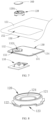
FIG. 2 is a schematic diagram of a structure of a decorative ring in an embodiment of an electronic device according to this application; -
FIG. 3 is a partial sectional view of an embodiment of an electronic device according to this application; -
FIG. 4 is a schematic diagram of a structure of a cover plate in an embodiment of an electronic device according to this application; -
FIG. 5 is another partial sectional view of an embodiment of an electronic device according to this application; -
FIG. 6 is another partial sectional view of an embodiment of an electronic device according to this application; -
FIG. 7 is a schematic diagram of a partial stereoscopic structure in an embodiment of an electronic device according to this application; and -
FIG. 8 is another schematic diagram of a structure of a decorative ring in an embodiment of an electronic device according to this application. - Reference signs: 100. electronic device; 110. camera; 111. base; 112. camera lens; 120. decorative ring; 120A. first through hole; 121. frame body; 122. skirt; 1221. strip edge; 123. avoidance space; 124. supporting table; 130. cover plate; 131. plate body; 132. mounting lug boss; 132A. second through hole; 133. mounting notch; 134. cover plate skirt; 140. motherboard support; 141. support body; 142. sealing lug boss; 150. battery cover; 151. cover body; 152. decorative hole; and 160. lens.
- Embodiments of this application are described in detail below, and examples of the embodiments are shown in the accompanying drawings, where same or similar designations throughout indicate same or similar elements or elements having a same or similar function. Embodiments described below with reference to the accompanying drawings are examples and are used only for the purpose of explaining this application but are not construed as a limitation on this application. Based on embodiments in this application, all other embodiments obtained by persons of ordinary skill in the art without creative efforts fall within the protection scope of this application.
- The terms "first" and "second" in the specification and claims of this application may expressly or impliedly include one or more of such features. In the descriptions of this application, "plurality" means two or more, unless otherwise specified. In addition, "and/or" in the specification and claims represents at least one of connected objects, and the character "/" generally indicates that the contextually associated objects have an "or" relationship.
- In the descriptions of this application, it should be understood that the orientations or positional relationships indicated by the terms "center", "vertical", "transverse", "length", "width", "thickness", "upper", "lower", "front", "rear", "left", "right", "perpendicular", "horizontal", "top", "bottom", "inside", "outside", "clockwise", "counterclockwise", "axial", " radial", "circumferential", and the like are based on the orientations or positional relationships shown in the accompanying drawings, are merely intended to facilitate the descriptions of this application and simplify the descriptions, are not intended to indicate or imply that the apparatuses or components mentioned in this application must have specific orientations, or be constructed and operated for a specific orientation, and therefore shall not be construed as a limitation to this application.
- In the descriptions of this application, it needs to be noted that, unless otherwise expressly provided and limited, the terms "mounting", "joint", and "connection" should be understood in a broad sense. For example, they may refer to a fixed connection, a detachable connection, or an integral connection; may refer to a mechanical connection or an electrical connection; and may refer to a direct connection, an indirect connection via an intermediate medium, or an internal communication between two elements.. Persons of ordinary skill in the art can understand specific meanings of these terms in this application based on specific situations.
- An
electronic device 100 in some embodiments of this application is described below with reference toFIG. 1 andFIG. 2 , and includes: - a
camera 110 including abase 111 and acamera lens 112 disposed at the top of thebase 111; and - a
decorative ring 120 including aframe body 121 and askirt 122, where theskirt 122 is disposed on an outer wall of theframe body 121 and extends from theframe body 121 in a direction away from theframe body 121; a first throughhole 120A is provided in theframe body 121, thecamera 110 faces the first throughhole 120A, and at least part of thecamera lens 112 is located in the first throughhole 120A; and theskirt 122 has anavoidance space 123, theavoidance space 123 is disposed in relation to top corners of thebase 111, and at least part of the top corner is disposed in theavoidance space 123. - In embodiments of this application, the
avoidance space 123 is designed on theskirt 122 of thedecorative ring 120, and the top corners of thebase 111 of thecamera 110 are at least partially disposed in theavoidance space 123, so that a fitting height between thecamera 110 and thedecorative ring 120 can be reduced, and an internal space of theelectronic device 100 can be optimized, thereby facilitating the thinning of theelectronic device 100. - The
camera 110 includes thebase 111 for fixing thecamera lens 112, and the top of thebase 111 is connected to the bottom of thecamera 112. Thebase 111 and thecamera lens 112 may be fixedly connected. To be specific, thecamera lens 112 is not able to swing relative to thebase 111, and a viewing angle of thecamera lens 112 is fixed in a case that thebase 111 is fixed. Alternatively, thebase 111 and thecamera lens 112 may be movably connected. In this case, thecamera lens 112 is able to swing relative to thebase 111, and a viewing direction of thecamera lens 112 can be adjusted in a case that thebase 111 is fixed. - The first through
hole 120A is provided in theframe body 121 of thedecorative ring 120, at least part of thecamera lens 112 is located in the first throughhole 120A, and thecamera lens 112 takes a view of the environment outside theelectronic device 100 through the first throughhole 120A. In the embodiments of this application, theframe body 121 may be an annular frame body. - In some embodiments, the
frame body 121 of thedecorative ring 120 surrounds thecamera lens 112 on a housing of theelectronic device 100 so as to protect thecamera lens 112 and improve aesthetics of the electronic device. - There may be a plurality of
avoidance spaces 123 on theskirt 122 of thedecorative ring 120, and a number ofavoidance spaces 123 is greater than or equal to the number of top corners of thebase 111 of thecamera 110. The base 111 may be a triangular prism structure, that is, thebase 111 has three top corners. In this case, there are at least threeavoidance spaces 123 on theskirt 122. Alternatively, thebase 111 may be a quadrangular prism structure, that is, thebase 111 has four top corners. In this case, there are at least fouravoidance spaces 123 on theskirt 122. Alternatively, thebase 111 may be a hexagonal prism structure, that is, thebase 111 has six top corners. In this case, there are at least sixavoidance spaces 123 on theskirt 122. - For example, the
base 111 of thecamera 110 is a rectangular frame structure (that is, a positive quadrangular prism structure), and the top corners of the base 111 are four corners on a side of the base 111 close to thedecorative ring 120. Theframe body 121 of thedecorative ring 120 may be an annular structure, the skirt of thedecorative ring 120 has four avoidance spaces, and the four top corners of the base 111 are disposed one by one correspondingly in the fouravoidance spaces 123. - Further, as shown in
FIG. 2 , theskirt 122 includes a plurality ofstrip edges 1221, where the plurality ofstrip edges 1221 are spaced apart from each other, and twoadjacent strip edges 1221 have theavoidance space 123. - One end of the
strip edge 1221 is connected to the bottom of theframe body 121 and the other end extends towards thebase 111 of thecamera 110. Thedecorative ring 120 can be matched to the top corners of thebase 111 of thecamera 110 with the help of the strip edges 1221 at a smaller outer diameter size. - A plurality of
strip edges 1221 are spaced apart from each other to partition a plurality ofavoidance spaces 123, meaning that the strip edges 1221 and theavoidance spaces 123 are arranged alternately. The strip edges 1221 and the top corners of thebase 111 of thecamera 110 are disposed in a staggered manner, and theavoidance spaces 123 are provided correspondingly to the top corners of thebase 111 of thecamera 110. A width of theavoidance space 123 may be greater than a width of thestrip edge 1221 or may be equal to the width of thestrip edge 1221. Awider avoidance space 123 facilitates the insertion of the top corner of thebase 111 of thecamera 110 into theavoidance space 123. - Further, the
electronic device 100 further includes acover plate 130. Thecover plate 130 includes aplate body 131 and a mountinglug boss 132 connected to theplate body 131, a second throughhole 132A is provided in the mountinglug boss 132, and the first throughhole 120A is in communication with the second throughhole 132A. Thedecorative ring 120 covers the mountinglug boss 132, and the mountinglug boss 132 is sealingly connected to the top corner of the base 111 through theavoidance space 123. - The
skirt 122 is formed by extending from the bottom of theframe body 121, and is connected to thecover plate 130 to mount theframe body 121 on thecover plate 130. Thedecorative ring 120 can be matched to a side of the mountinglug boss 132 with the help of theskirt 122 in a case that theframe body 121 maintains a small outer diameter size. - As shown in
FIG. 3 , a sealing member may be provided between the mountinglug boss 132 and thedecorative ring 120, so that the mountinglug boss 132 is sealingly connected to thedecorative ring 120 through the sealing member. In addition, a sealing member may be further provided between the mountinglug boss 132 and each of the top corners of thebase 111 of thecamera 110, so that the mountinglug boss 132 is sealingly connected to the top corner of thebase 111 of thecamera 110 through the sealing member. In this way, the mountinglug boss 132 can provide double-sided sealing for thedecorative ring 120 and thecamera 110. - After the mounting
lug boss 132 seals the top corners of thebase 111 of thecamera 110, theskirt 122 can cover the side of the mountinglug boss 132. In addition, due to the fact that theavoidance space 123 is provided correspondingly to the top corner of thebase 111 of thecamera 110, a sealing thickness at the top corner of thebase 111 of thecamera 110 does not increase, meaning that an overall thickness of the electronic device does not increase while satisfying double-layer sealing for thecamera 110. This is convenient for the thinning of the electronic device. - The
cover plate 130 may be a rectangular structure corresponding to thebase 111 of thecamera 110. Specifically, an outer contour of theplate body 131 is rectangular. - Further, the
cover plate 130 may further include a plurality of mountingnotches 133 provided between the mountinglug boss 132 and theplate body 131, and theskirt 122 is inserted into the mountingnotches 133. - The bottom of the mounting
lug boss 132 is connected to an edge of theplate body 131, where the mountingnotches 133 are provided in a connection area, and theskirt 122 is inserted in the mountingnotches 133. - In some embodiments, the
strip edge 1221 of theskirt 122 may include a first extension portion extending from theframe body 121 in a direction towards thecamera 110 and a second extension portion extending outwardly from an end of the first extension portion. The second extension portion is disposed parallel to theplate body 131. - The mounting
notches 133 are provided on a side of thecover plate 130 facing thedecorative ring 120, so that the second extension portion of theskirt 122 is inserted into the mountingnotches 133. In this way, the second extension portion abuts against notch bases of the mountingnotches 133 when theframe body 121 abuts against thecover plate 130, to restrict a mounting position of thedecorative ring 120 on thecover plate 130, and to improve a degree of mutual coordination of various structures in an internal space of a product. - The number of mounting
notches 133 may be equal to a number ofskirts 122. The plurality of mountingnotches 133 are disposed in one-to-one correspondence with the plurality ofstrip edges 1221 of theskirts 122. - Further, as shown in
FIG. 1 , the mountinglug boss 132 is located on a side of theplate body 131 close to thedecorative ring 120; or as shown inFIG. 4 , a surface of the mountinglug boss 132 close to thedecorative ring 120 is flush with a surface of theplate body 131 close to thedecorative ring 120. - In this embodiment, the mounting
lug boss 132 is connected to theplate body 131 through an extension band, and a height between the mountinglug boss 132 and theplate body 131 can be adjusted depending on an actual situation. For example, the mountinglug boss 132 may be located on a side of theplate body 131 close to thecamera 110. To be specific, the extension band extends in a direction from the edge of theplate body 131 to thecamera 110 to support the mountinglug boss 132. To reduce an overall thickness of thecover plate 130, the mountinglug boss 132 is disposed on the side of theplate body 131 close to thedecorative ring 120, so that thecover plate 130 can be thinned, a weight can be reduced, and the electronic device can be made thinner and lighter. Thecover plate 130 is able to seal thebase 111 of thecamera 110 in an extremely thin case without increasing an outer diameter of thedecorative ring 120, ensuring an appearance requirement. - For another example, the surface of the mounting
lug boss 132 close to thedecorative ring 120 is flush with the surface of theplate body 131 close to thedecorative ring 120. In other words, the extension strip extends in a direction parallel to, or recessed in, theplate body 131, to connect to the mountinglug boss 132. In this way, the thickness of thecover plate 130 can be satisfied, allowing thecover plate 130 to be provided with larger notches to match alarger base 111 of thecamera 110. - Further, as shown in
FIG. 3 andFIG. 5 , thebase 111 of thecamera 110 is of a rectangular body structure, four top corners of the base 111 are each provided with a notch, and notch bases of the notches are connected to the bottom of the mountinglug boss 132. - In this embodiment, the notches are provided at the four top corners of the
base 111 of thecamera 110, and a shape of the mountinglug boss 132 at positions corresponding to the notches can be designed to match the notches at the top corners of thebase 111, so that no space is left between the top corners of thebase 111 of thecamera 110 and the mountinglug boss 132 of thecover plate 130, as shown inFIG. 5 . The shape of the mountinglug boss 132 at the positions corresponding to the notches may alternatively be designed as a platform. In this case, the mountinglug boss 132 is sealingly connected to a notch wall top of the notch at each of the top corners of the base 111 through a sealing member, as shown inFIG. 3 . - When no notch is provided at the top corners of the
base 111 of thecamera 110, an inner diameter of theframe body 121 is at least larger than a diagonal size of thebase 111 of thecamera 110. After notches are provided at the top corners of thebase 111 of thecamera 110, the inner diameter of theframe body 121 is at least larger than a diagonal size of a notch top of thebase 111 of thecamera 110. Therefore, a requirement for the inner diameter of theframe body 121 can be reduced by providing the notches at the top corners of thebase 111 of thecamera 110, thereby facilitating miniaturization of thedecorative ring 121. - Further, as shown in
FIG. 6 , amotherboard support 140 is further included, where themotherboard support 140 includes asupport body 141 and a sealinglug boss 142 connected to thesupport body 141, a third through hole is provided in the sealinglug boss 142, and the third through hole is in communication with the second throughhole 132A. - The sealing
lug boss 142 is sandwiched between the mountinglug boss 132 and each of the top corners of thebase 111 of thecamera 110 through a sealing member, and the notch bases of the notches are connected to the bottom of the sealinglug boss 142. - In this embodiment, the
camera 110 is sealed by adding themotherboard support 140 to a side of thecover plate 130 close to thecamera 110. Thecamera lens 112 of thecamera 110 is inserted into the third through hole 143 disposed on the sealinglug boss 142. - The
cover plate 130 or themotherboard support 140 can cover thecamera 110 in all directions, to prevent a hole from exposing the top corner of thebase 111 of thecamera 110, and to prevent thecamera 110 from a risk of static electricity. - In the embodiments of this application, the mentioned sealing members may all include sealing foam or may be made of other sealing materials, which is not limited herein.
- Further, the electronic device further includes a
battery cover 150, where thebattery cover 150 includes acover body 151 and adecorative hole 152 that passes through thecover body 151. Thecover plate 151 further includes acover plate skirt 134 extending outwardly from an edge of theplate body 131, thecover plate skirt 134 is in communication with an edge of thedecorative hole 152, and thedecorative ring 120 is located in thedecorative hole 152. - The
battery cover 150 may be provided with the decorative hole 241 of a shape corresponding to that of therectangular plate body 131, and thecover plate 130 is secured, through thecover plate skirt 134 on the edge of theplate body 131, to the edge of thedecorative hole 152 of thebattery cover 150 close to a surface thecamera 110, and thecamera 110, the mountinglug boss 132, the sealinglug boss 142, and thedecorative ring 120 are all disposed in thedecorative hole 152. - Further, as shown in
FIG. 3 , the electronic device further includes alens 160. - The
decorative ring 120 may further include a supporting table 124 extending inwardly from theframe body 121 to form the first throughhole 120A, and the supporting table 124 carries thelens 160 to allow thelens 160 to cover a viewing angle of thecamera lens 112. - The supporting table 124 extends inwardly from the
frame body 121 to form an annular structure having the first throughhole 120A. The supporting table 124 is configured to carry thelens 160, while an inner wall of theframe body 121 is capable of abutting against an edge of thelens 160 to restrict thelens 160 and prevent thelens 160 from falling out. - The
lens 160 is made of a transparent material, and is capable of protecting thecamera lens 112 by preventing direct external impact on thecamera lens 112, without affecting viewing of thecamera lens 112. Specifically, thelens 160 can be made of a hard glass material. - A center of the
camera lens 112 of thecamera 110 is located on a central axis of the first throughhole 120A, and an area of the first throughhole 120A is larger than an area of a viewfinder of thecamera lens 112 of thecamera 110. - A surface of the supporting table 124 close to the
camera 110 abuts against a top surface of the mountinglug boss 132. Specifically, the supporting table 124 can be attached to the top surface of the mountinglug boss 132 with a back adhesive, so as to implement sealing between the supporting table 124 and thecover plate 130. - In some other embodiments, the
decorative ring 120 may alternatively be provided with no supporting table 124, where thelens 160 is supported by the mountinglug boss 132 located in theframe body 121. As shown inFIG. 5 and FIG. 6 , the top surface of the mountinglug boss 132 abuts against thelens 160 to support thelens 160. - Further, a top surface of the
camera lens 160 may be flush with a top surface of theframe body 121, so as to improve aesthetics of the electronic device. - Further, the
decorative ring 120 further includes a first edge extending from an edge of theskirt 122 in a direction perpendicular to theskirt 122 and a second edge extending from the bottom of theframe body 121 in a direction perpendicular to the outer wall of theframe body 121. The first edge and the second edge are integrally molded to form an upper-lower step structure. - A space directly opposite the second edge is an avoidance space of the
skirt 122, and also is a space between an upper step and two adjacent lower steps in the step structure. The top corners of thebase 111 of thecamera 110 are disposed correspondingly to the second edge, so that the fitting height between thecamera 110 and thedecorative ring 120 can be reduced and the internal space of theelectronic device 100 is optimized, thereby facilitating the thinning of theelectronic device 100. - In the embodiments of this application, "up" and "top" refer to a direction away from the camera, and "down" and "bottom" refer to a direction close to the camera.
- The electronic device provided in the embodiments of this application, with the assistance of the
skirt 122, further has the following advantages in a case that thedecorative ring 120 can satisfy a smaller outer diameter size of the frame body 121: - 1. It can avoid the
decorative ring 120 enlarging and thus prevent the distance between thedecorative ring 120 and thebattery cover 150 from being decreased, so as to ensure structural strength of an edge of thebattery cover 150 and improve safety of the electronic device. - 2. It can avoid the
decorative ring 120 enlarging and thus prevent the gap between thedecorative ring 120 and the battery from being too small, so as to prevent static electricity from affecting thecamera 110 while ensuring safety of the battery. - 3. It can avoid the
decorative ring 120 enlarging and compressing an antenna headroom area of a frame of the electronic device, so as to ensure that antenna performance is guaranteed. - 4. The flexible arrangement of the camera module allows for arranging the
camera 110 as close to the edge of theelectronic device 100 as possible. This concentrated arrangement of components on the motherboard optimizes component arrangement on the motherboard. - The electronic device according to the embodiments of this application may be any electronic device suitable for including a sensor package structure, such as a mobile phone, a laptop, a tablet computer, or a wearable device.
- It should be noted that in this specification, the terms "include" and "comprise", or any of their variants are intended to cover a non-exclusive inclusion, such that a process, method, article, or apparatus that includes a list of elements not only includes those elements but also includes other elements that are not expressly listed, or further includes elements inherent to such process, method, article, or apparatus. In absence of more constraints, an element preceded by "includes a... " does not preclude the existence of other identical elements in the process, method, article, or apparatus that includes the element. Furthermore, it should be noted that the scope of the methods and apparatuses in the embodiments of this application is not limited to performing the functions in the order shown or discussed, but may also include performing the functions in a substantially simultaneous manner or in a reverse order depending on the functions involved. For example, the described methods may be performed in an order different from that described, and various steps may be added, omitted, or combined. In addition, features described with reference to some examples may be combined in other examples.
- The foregoing describes embodiments of this application in combination with the accompanying drawings, but this application is not limited to the foregoing specific implementations. The foregoing specific implementations are merely schematic rather than restrictive. Those of ordinary skill in the art can make many forms under the inspiration of this application, without departing from a tenet of this application and the scope protected by the claims, all of which belong to the protection scope of this application.
Claims (10)
- An electronic device, comprising:a camera comprising a base and a camera lens disposed at the top of the base; anda decorative ring comprising a frame body and a skirt, wherein the skirt is disposed on an outer wall of the frame body and extends from the frame body in a direction away from the frame body; a first through hole is provided in the frame body, the camera faces the first through hole, and at least part of the camera lens is located in the first through hole; and the skirt has an avoidance space, the avoidance space is disposed in relation to top corners of the base, and at least part of the top corner is disposed in the avoidance space.
- The electronic device according to claim 1, wherein the skirt comprises a plurality of strip edges, the plurality of strip edges are spaced apart from each other, and two adjacent strip edges have the avoidance space.
- The electronic device according to claim 1, further comprising a cover plate, wherein the cover plate comprises a plate body and a mounting lug boss connected to the plate body, a second through hole is provided in the mounting lug boss, and the first through hole is in communication with the second through hole; and the decorative ring covers the mounting lug boss, and the mounting lug boss is sealingly connected to the top corner of the base through the avoidance space.
- The electronic device according to claim 3, wherein the cover plate further comprises a plurality of mounting notches provided between the mounting lug boss and the plate body, and the skirt is inserted into the mounting notches.
- The electronic device according to claim 3, wherein the mounting lug boss is located on a side of the plate body close to the decorative ring; or a surface of the mounting lug boss close to the decorative ring is flush with a surface of the plate body close to the decorative ring.
- The electronic device according to claim 3, wherein the base of the camera is of a rectangular body structure, four top corners of the base are each provided with a notch, and notch bases of the notches are connected to the bottom of the mounting lug boss.
- The electronic device according to claim 6, further comprising a motherboard support, wherein the motherboard support comprises a support body and a sealing lug boss connected to the support body, a third through hole is provided in the sealing lug boss, and the third through hole is in communication with the second through hole; and
the sealing lug boss is sandwiched between the mounting lug boss and each of the top corners of the base of the camera through a sealing member, and the notch bases of the notches are connected to the bottom of the sealing lug boss. - The electronic device according to claim 7, wherein the sealing member comprises sealing foam.
- The electronic device according to claim 3, further comprising a battery cover, wherein the battery cover comprises a cover body and a decorative hole that passes through the cover body; and the cover plate further comprises a cover plate skirt extending outwardly from an edge of the plate body, the cover plate skirt is connected to an edge of the decorative hole, and the decorative ring is located in the decorative hole.
- The electronic device according to claim 1, further comprising a lens, wherein
the decorative ring further comprises a supporting table extending inwardly from the frame body to form the first through hole, and the supporting table carries the lens to allow the lens to cover a viewing angle of the camera lens.
Applications Claiming Priority (2)
| Application Number | Priority Date | Filing Date | Title |
|---|---|---|---|
| CN202111264826.5A CN113810586B (en) | 2021-10-28 | 2021-10-28 | Electronic equipment |
| PCT/CN2022/126627 WO2023071927A1 (en) | 2021-10-28 | 2022-10-21 | Information display method and electronic device |
Publications (3)
| Publication Number | Publication Date |
|---|---|
| EP4425908A1 true EP4425908A1 (en) | 2024-09-04 |
| EP4425908A4 EP4425908A4 (en) | 2025-03-05 |
| EP4425908B1 EP4425908B1 (en) | 2025-12-03 |
Family
ID=78898320
Family Applications (1)
| Application Number | Title | Priority Date | Filing Date |
|---|---|---|---|
| EP22885804.9A Active EP4425908B1 (en) | 2021-10-28 | 2022-10-21 | Information display method and electronic device |
Country Status (5)
| Country | Link |
|---|---|
| US (1) | US20240275874A1 (en) |
| EP (1) | EP4425908B1 (en) |
| CN (1) | CN113810586B (en) |
| ES (1) | ES3058558T3 (en) |
| WO (1) | WO2023071927A1 (en) |
Families Citing this family (3)
| Publication number | Priority date | Publication date | Assignee | Title |
|---|---|---|---|---|
| CN113810586B (en) * | 2021-10-28 | 2023-02-17 | 维沃移动通信有限公司 | Electronic equipment |
| CN115278022B (en) * | 2022-07-28 | 2024-04-26 | 维沃移动通信有限公司 | Electronic equipment |
| CN116320114B (en) * | 2023-03-20 | 2025-09-23 | 维沃移动通信有限公司 | electronic devices |
Family Cites Families (15)
| Publication number | Priority date | Publication date | Assignee | Title |
|---|---|---|---|---|
| US3188930A (en) * | 1962-10-29 | 1965-06-15 | Eastman Kodak Co | Simulated lens mount |
| CN202523895U (en) * | 2011-11-29 | 2012-11-07 | 深圳市电连精密技术有限公司 | Connector for camera module |
| CN204886938U (en) * | 2015-09-02 | 2015-12-16 | 广东欧珀移动通信有限公司 | A camera decoration and mobile terminal |
| CN107528946B (en) * | 2017-09-26 | 2020-07-17 | Oppo广东移动通信有限公司 | Camera module and mobile terminal |
| CN109976447B (en) * | 2017-12-28 | 2021-03-09 | Oppo广东移动通信有限公司 | Functional module, electronic device and control method of electronic device |
| CN109862242B (en) * | 2019-01-28 | 2022-01-18 | Oppo广东移动通信有限公司 | Electronic device |
| CN110035213B (en) * | 2019-05-24 | 2024-04-05 | 深圳市兆威机电股份有限公司 | Camera mechanism and electronic equipment |
| CN210609423U (en) * | 2019-12-30 | 2020-05-22 | 深圳Tcl新技术有限公司 | Camera and electronic device |
| CN113225453B (en) * | 2020-02-05 | 2022-02-15 | 荣耀终端有限公司 | Electronic device |
| CN112437219A (en) * | 2020-11-30 | 2021-03-02 | Oppo广东移动通信有限公司 | Camera shooting assembly and electronic equipment |
| CN214480715U (en) * | 2021-03-31 | 2021-10-22 | 维沃移动通信有限公司 | Electronic device |
| CN113542548B (en) * | 2021-06-04 | 2023-12-26 | 维沃移动通信有限公司 | Camera structure and electronics |
| CN113242341B (en) * | 2021-06-16 | 2023-12-22 | 维沃移动通信有限公司 | Electronic equipment |
| CN113489875A (en) * | 2021-07-23 | 2021-10-08 | 维沃移动通信有限公司 | Electronic equipment |
| CN113810586B (en) * | 2021-10-28 | 2023-02-17 | 维沃移动通信有限公司 | Electronic equipment |
-
2021
- 2021-10-28 CN CN202111264826.5A patent/CN113810586B/en active Active
-
2022
- 2022-10-21 EP EP22885804.9A patent/EP4425908B1/en active Active
- 2022-10-21 WO PCT/CN2022/126627 patent/WO2023071927A1/en not_active Ceased
- 2022-10-21 ES ES22885804T patent/ES3058558T3/en active Active
-
2024
- 2024-04-26 US US18/647,610 patent/US20240275874A1/en active Pending
Also Published As
| Publication number | Publication date |
|---|---|
| US20240275874A1 (en) | 2024-08-15 |
| WO2023071927A1 (en) | 2023-05-04 |
| EP4425908A4 (en) | 2025-03-05 |
| EP4425908B1 (en) | 2025-12-03 |
| CN113810586B (en) | 2023-02-17 |
| ES3058558T3 (en) | 2026-03-11 |
| CN113810586A (en) | 2021-12-17 |
Similar Documents
| Publication | Publication Date | Title |
|---|---|---|
| EP4425908B1 (en) | Information display method and electronic device | |
| US9639148B2 (en) | Mobile information terminal | |
| KR102843993B1 (en) | Foldable electronic device including elastic means | |
| WO2024045746A1 (en) | Folding screen assembly and electronic device | |
| US20100265431A1 (en) | Protecting module and portable electronic device using the same | |
| EP2664074A2 (en) | Electronic device case with retractable stand | |
| JP5417478B2 (en) | Electronics | |
| US20120211613A1 (en) | Holder for portable electronic device background | |
| CN111405089A (en) | Display module and its manufacturing method, and electronic equipment | |
| KR102902126B1 (en) | Electronic device including sealing member | |
| CN113760050B (en) | Screen assembly of electronic equipment and electronic equipment | |
| EP4228231A1 (en) | Electronic device and method for assembling electronic device | |
| EP4216685A1 (en) | Electronic assembly and electronic apparatus | |
| US20230412058A1 (en) | Vibration Motor and Terminal Device | |
| KR101275832B1 (en) | Display device and cover of electronic device | |
| CN208158647U (en) | Display screen, terminal display assembly and mobile terminal | |
| EP4498663B1 (en) | Audio device and terminal device | |
| EP4030411A1 (en) | Flexible display screen and electronic device | |
| EP4676013A1 (en) | Electronic device | |
| CN218450194U (en) | Waterproof mobile phone and shell thereof | |
| CN213990712U (en) | electronic device | |
| EP4525417A1 (en) | Folding electronic device | |
| CN211656223U (en) | Camera support, camera assembly and electronic equipment | |
| EP2434367B1 (en) | Gasket and display assembly for an electronic mobile device | |
| JP2025525264A (en) | Lens device and electronic device |
Legal Events
| Date | Code | Title | Description |
|---|---|---|---|
| STAA | Information on the status of an ep patent application or granted ep patent |
Free format text: STATUS: THE INTERNATIONAL PUBLICATION HAS BEEN MADE |
|
| PUAI | Public reference made under article 153(3) epc to a published international application that has entered the european phase |
Free format text: ORIGINAL CODE: 0009012 |
|
| STAA | Information on the status of an ep patent application or granted ep patent |
Free format text: STATUS: REQUEST FOR EXAMINATION WAS MADE |
|
| 17P | Request for examination filed |
Effective date: 20240514 |
|
| AK | Designated contracting states |
Kind code of ref document: A1 Designated state(s): AL AT BE BG CH CY CZ DE DK EE ES FI FR GB GR HR HU IE IS IT LI LT LU LV MC ME MK MT NL NO PL PT RO RS SE SI SK SM TR |
|
| DAV | Request for validation of the european patent (deleted) | ||
| DAX | Request for extension of the european patent (deleted) | ||
| A4 | Supplementary search report drawn up and despatched |
Effective date: 20250131 |
|
| RIC1 | Information provided on ipc code assigned before grant |
Ipc: G03B 17/56 20210101ALI20250127BHEP Ipc: H04N 23/55 20230101ALI20250127BHEP Ipc: H04N 23/51 20230101ALI20250127BHEP Ipc: H04M 1/02 20060101ALI20250127BHEP Ipc: G03B 17/02 20210101ALI20250127BHEP Ipc: H04N 5/222 20060101AFI20250127BHEP |
|
| GRAP | Despatch of communication of intention to grant a patent |
Free format text: ORIGINAL CODE: EPIDOSNIGR1 |
|
| STAA | Information on the status of an ep patent application or granted ep patent |
Free format text: STATUS: GRANT OF PATENT IS INTENDED |
|
| RIC1 | Information provided on ipc code assigned before grant |
Ipc: H04N 5/222 20060101AFI20250707BHEP Ipc: G03B 17/02 20210101ALI20250707BHEP Ipc: H04M 1/02 20060101ALI20250707BHEP Ipc: H04N 23/51 20230101ALI20250707BHEP Ipc: H04N 23/55 20230101ALI20250707BHEP Ipc: G03B 17/56 20210101ALI20250707BHEP |
|
| INTG | Intention to grant announced |
Effective date: 20250717 |
|
| GRAS | Grant fee paid |
Free format text: ORIGINAL CODE: EPIDOSNIGR3 |
|
| GRAA | (expected) grant |
Free format text: ORIGINAL CODE: 0009210 |
|
| STAA | Information on the status of an ep patent application or granted ep patent |
Free format text: STATUS: THE PATENT HAS BEEN GRANTED |
|
| AK | Designated contracting states |
Kind code of ref document: B1 Designated state(s): AL AT BE BG CH CY CZ DE DK EE ES FI FR GB GR HR HU IE IS IT LI LT LU LV MC ME MK MT NL NO PL PT RO RS SE SI SK SM TR |
|
| REG | Reference to a national code |
Ref country code: CH Ref legal event code: F10 Free format text: ST27 STATUS EVENT CODE: U-0-0-F10-F00 (AS PROVIDED BY THE NATIONAL OFFICE) Effective date: 20251203 Ref country code: GB Ref legal event code: FG4D |
|
| REG | Reference to a national code |
Ref country code: DE Ref legal event code: R096 Ref document number: 602022026352 Country of ref document: DE |
|
| REG | Reference to a national code |
Ref country code: IE Ref legal event code: FG4D |
|
| REG | Reference to a national code |
Ref country code: NL Ref legal event code: FP |
|
| REG | Reference to a national code |
Ref country code: ES Ref legal event code: FG2A Ref document number: 3058558 Country of ref document: ES Kind code of ref document: T3 Effective date: 20260311 |
|
| REG | Reference to a national code |
Ref country code: LT Ref legal event code: MG9D |
|
| PG25 | Lapsed in a contracting state [announced via postgrant information from national office to epo] |
Ref country code: NO Free format text: LAPSE BECAUSE OF FAILURE TO SUBMIT A TRANSLATION OF THE DESCRIPTION OR TO PAY THE FEE WITHIN THE PRESCRIBED TIME-LIMIT Effective date: 20260303 |
|
| PG25 | Lapsed in a contracting state [announced via postgrant information from national office to epo] |
Ref country code: FI Free format text: LAPSE BECAUSE OF FAILURE TO SUBMIT A TRANSLATION OF THE DESCRIPTION OR TO PAY THE FEE WITHIN THE PRESCRIBED TIME-LIMIT Effective date: 20251203 Ref country code: HR Free format text: LAPSE BECAUSE OF FAILURE TO SUBMIT A TRANSLATION OF THE DESCRIPTION OR TO PAY THE FEE WITHIN THE PRESCRIBED TIME-LIMIT Effective date: 20251203 |
|
| PG25 | Lapsed in a contracting state [announced via postgrant information from national office to epo] |
Ref country code: RS Free format text: LAPSE BECAUSE OF FAILURE TO SUBMIT A TRANSLATION OF THE DESCRIPTION OR TO PAY THE FEE WITHIN THE PRESCRIBED TIME-LIMIT Effective date: 20260303 |
|
| PG25 | Lapsed in a contracting state [announced via postgrant information from national office to epo] |
Ref country code: PL Free format text: LAPSE BECAUSE OF FAILURE TO SUBMIT A TRANSLATION OF THE DESCRIPTION OR TO PAY THE FEE WITHIN THE PRESCRIBED TIME-LIMIT Effective date: 20251203 |
|
| PG25 | Lapsed in a contracting state [announced via postgrant information from national office to epo] |
Ref country code: LV Free format text: LAPSE BECAUSE OF FAILURE TO SUBMIT A TRANSLATION OF THE DESCRIPTION OR TO PAY THE FEE WITHIN THE PRESCRIBED TIME-LIMIT Effective date: 20251203 |
|
| PG25 | Lapsed in a contracting state [announced via postgrant information from national office to epo] |
Ref country code: BG Free format text: LAPSE BECAUSE OF FAILURE TO SUBMIT A TRANSLATION OF THE DESCRIPTION OR TO PAY THE FEE WITHIN THE PRESCRIBED TIME-LIMIT Effective date: 20251203 |