EP4425879A1 - Knotenschutzverfahren und -vorrichtung, elektronische vorrichtung und medium - Google Patents
Knotenschutzverfahren und -vorrichtung, elektronische vorrichtung und medium Download PDFInfo
- Publication number
- EP4425879A1 EP4425879A1 EP22964720.1A EP22964720A EP4425879A1 EP 4425879 A1 EP4425879 A1 EP 4425879A1 EP 22964720 A EP22964720 A EP 22964720A EP 4425879 A1 EP4425879 A1 EP 4425879A1
- Authority
- EP
- European Patent Office
- Prior art keywords
- node
- sid
- primary
- backup
- service packet
- Prior art date
- Legal status (The legal status is an assumption and is not a legal conclusion. Google has not performed a legal analysis and makes no representation as to the accuracy of the status listed.)
- Pending
Links
Images


Classifications
-
- H—ELECTRICITY
- H04—ELECTRIC COMMUNICATION TECHNIQUE
- H04L—TRANSMISSION OF DIGITAL INFORMATION, e.g. TELEGRAPHIC COMMUNICATION
- H04L45/00—Routing or path finding of packets in data switching networks
- H04L45/24—Multipath
- H04L45/247—Multipath using M:N active or standby paths
-
- H—ELECTRICITY
- H04—ELECTRIC COMMUNICATION TECHNIQUE
- H04L—TRANSMISSION OF DIGITAL INFORMATION, e.g. TELEGRAPHIC COMMUNICATION
- H04L45/00—Routing or path finding of packets in data switching networks
- H04L45/28—Routing or path finding of packets in data switching networks using route fault recovery
-
- H—ELECTRICITY
- H04—ELECTRIC COMMUNICATION TECHNIQUE
- H04L—TRANSMISSION OF DIGITAL INFORMATION, e.g. TELEGRAPHIC COMMUNICATION
- H04L45/00—Routing or path finding of packets in data switching networks
- H04L45/22—Alternate routing
-
- H—ELECTRICITY
- H04—ELECTRIC COMMUNICATION TECHNIQUE
- H04L—TRANSMISSION OF DIGITAL INFORMATION, e.g. TELEGRAPHIC COMMUNICATION
- H04L45/00—Routing or path finding of packets in data switching networks
- H04L45/34—Source routing
-
- H—ELECTRICITY
- H04—ELECTRIC COMMUNICATION TECHNIQUE
- H04L—TRANSMISSION OF DIGITAL INFORMATION, e.g. TELEGRAPHIC COMMUNICATION
- H04L45/00—Routing or path finding of packets in data switching networks
- H04L45/50—Routing or path finding of packets in data switching networks using label swapping, e.g. multi-protocol label switch [MPLS]
-
- H—ELECTRICITY
- H04—ELECTRIC COMMUNICATION TECHNIQUE
- H04L—TRANSMISSION OF DIGITAL INFORMATION, e.g. TELEGRAPHIC COMMUNICATION
- H04L45/00—Routing or path finding of packets in data switching networks
- H04L45/56—Routing software
- H04L45/566—Routing instructions carried by the data packet, e.g. active networks
Definitions
- the present application relates to the technical field of communications, and in particular, to a node protection method, device, electronic equipment, and medium.
- VoIP Voice over Internet Protocol
- An objective of embodiments of the present application is to provide a node protection method, device, electronic equipment, and medium, so as to enhance reliability of an SRv6 tail node and increase network reliability.
- Specific technical solutions are as follows:
- the present application provides a node protection method applied to a first node, comprising:
- the block of obtaining a first service packet comprises:
- the obtaining a first service packet comprises:
- the updating a destination address in the first IPv6 basic header based on a node status of the primary tail node, a node status of the backup tail node, and the second SID list, to obtain the first service packet comprises:
- the updating a destination address in the first IPv6 basic header based on a node status of the primary tail node, a node status of the backup tail node, and the second SID list, to obtain the first service packet comprises:
- the forwarding the first service packet comprises:
- the preset flag bit is set to a first value, the SID encapsulated in the second last element contained in the first SID list is the primary SID, and the SID encapsulated in the last element is the backup SID; the preset flag bit is set to a second value, and the SID encapsulated in the last element contained in the first SID list is the primary SID.
- the first value is 1 or 0.
- the first SRH extension header further contains Flags field in which a flag bit is the preset flag bit.
- the present application provides a node protection device applied to a first node, comprising:
- the obtaining module is specifically to:
- the obtaining module is specifically to:
- the obtaining module is specifically to:
- the obtaining module is specifically to:
- the forwarding module is specifically to strip off the outer encapsulation of the first service packet, to obtain an original packet; and forward the original packet.
- the preset flag bit is set to a first value, the SID encapsulated in the second last element contained in the first SID list is the primary SID, and the SID encapsulated in the last element is the backup SID; the preset flag bit is set to a second bit, and the SID encapsulated in the last element contained in the first SID list is the primary SID.
- the first value is 1 or 0.
- the first SRH extension header further contains Flags field in which a flag bit is the preset flag bit.
- the present application provides an electronic equipment comprising:
- the machine executable instructions specifically cause the processor to execute the following blocks of:
- the machine executable instructions specifically cause the processor to execute the following blocks of:
- machine executable instructions specifically cause the processor to execute the following blocks of:
- machine executable instructions specifically cause the processor to execute the following blocks of:
- the machine executable instructions specifically cause the processor to execute the following blocks of: stripping off the outer encapsulation of the first service packet, to obtain an original packet; and forwarding the original packet.
- the preset flag bit is set to a first value, the SID encapsulated in the second last element contained in the first SID list is the primary SID, and the SID encapsulated in the last element is the backup SID; the preset flag bit is set to a second bit, and the SID encapsulated in the last element contained in the first SID list is the primary SID.
- the first value is 1 or 0.
- the first SRH extension header further contains a Flags field in which a flag bit is the preset flag bit.
- the present application provides a machine readable storage medium storing machine executable instructions, the machine executable instructions, when called and executed by a processor, causing the processor to: implement the blocks of any described node protection method.
- a preset flag bit is added to an SRH extension header by means of which it is indicated that the SRH extension header carries a backup SID.
- the SID of a backup tail node is added to an SID list contained in the SRH extension header. Based on the preset flag bit and the SID of the backup tail node contained in the SID list, in the event that the primary tail node is unreachable but the backup tail node is reachable, the first node can send the first service packet to the backup tail node for the back tail node to send the first service packet to a destination device corresponding to the original packet.
- Segment Routing uses a source node routing mechanism.
- a Segment Identifier (SID) of a Segment that a forwarding path will pass is encapsulated in advance in a source node.
- SID Segment Identifier
- the SR node forwards the packet based on the SID of the packet.
- Segment Routing IPv6 means realization of SR based on an IPv6 forwarding plane.
- SRv6 can insert a routing extension header, i.e., a Segment Routing Header (SRH), in an IPv6 packet, and add the SIDs of all the Segments that a forwarding path will pass, i.e., an SID list, in the SRH, thus explicitly indicating the forwarding path of the IPv6 packet.
- SRv6 provides a flexible and highly efficient control means for a Software Defined Wide Area Network (SD-WAN). It has the characteristics of being easy to deploy and easy to expand, can better achieve traffic scheduling and path optimization, ensures the quality of key services, balances traffic distribution, increases utilization of dedicated lines, and reduces line costs.
- SD-WAN Software Defined Wide Area Network
- nodes in an SRv6 can be classified into the following several roles:
- the same node can play different roles in different SRv6 paths.
- one node is a source node in an SRv6 path and can be a relay node or an Endpoint node in another SRv6 path.
- an SID is configured to define a certain network function or represent a certain network instruction.
- the format of an SRv6 SID is in the form of an IPv6 address. As shown in Fig. 1 , the SRv6 SID is composed of Locator field, Function field, Arguments field, and MBZ (Must be zero) field.
- Locator used to identify the network segment to which an SID belongs. Locator is unique in an SR domain.
- Arguments used to define information such as flow and service of a packet.
- MBZ (Must be zero): in the event that the sum of the bits of Locator, Function, and Arguments is smaller than 128 bits, the other bits are filled with 0.
- the format of encapsulating an SRv6 packet is that: a new IPv6 basic header and an SRH are added to the outer layer of an original three-layer data packet.
- An SRH is a routing extension header with the routing type of 4.
- the format of an SRv6 packet is as shown in Fig. 2 .
- An SRv6 packet contains an IPv6 basic header, an SRH, and an original packet.
- the IPv6 basic header contains: Version (Ver), Traffic class, Flow Label, Payload Length, Next header, Hop limit, Source Address (SA), and Destination Address (DA).
- Next header takes a value of 43, representing that the next header is a routing extension header.
- the SRH contains: Next Header, with a length of 8 bits, which is used to identify the type of the next packet header.
- Hdr Ext Len with a length of 8 bits, representing the length of an SRH header in units of 8 bytes, not including the first 8 bytes.
- Routing Type with a length of 8 bits and a value of 4, representing that an SRH is carried.
- Segments Left (SL), with a length of 8 bits, representing the serial number of the next SID to be looked up, taking an initial value of n-1, n representing the number of SIDs encapsulated in the SRH, the value of SL decreasing by 1 every time an endpoint node is passed.
- Last Entry with a length of 8 bits, taking a value being the serial number of the first SID of a packet actual forwarding path in the SRH.
- Flags with a length of 8 bits, which is flag bit information.
- Segment List which is an SID list, with nodes on a packet forwarding path arranged in the order from far to near, in other words, Segment List [0] representing the last SID of the forwarding path, Segment List [1] representing the second last SID of the forwarding path, so on and so forth.
- device A in Fig. 3 is a source node
- device C and device E are Endpoint nodes
- device B and device D are relay nodes.
- Block 1 after device A, as a source node, receives an original packet, it encapsulates an SRH and an IPv6 basic header for the original packet, looks for a routing table based on the destination address in the encapsulated IPv6 basic header, and thus forwards the encapsulated packet to device B.
- the source address is the address of device A
- Block 2 after device B receives the packet, it looks up a routing table based on the destination address in the IPv6 basic header, and forwards the packet to device C.
- Block 4 after device D receives the packet, it looks up a routing table based on the destination address in the IPv6 basic header, and forwards the packet to device E.
- CE is multi-homed to a plurality of tail nodes.
- a source node after learning the multi-homing routing of CE by means of a routing protocol, determines a most optimal path and a second most optimal path based on a routing optimization strategy, the exit device on the most optimal path being a primary tail node the SID of which serves as a primary SID, the exit device on the second most optimal path being a backup tail node the SID of which serves as a backup SID.
- the most optimal path is a primary path and the second most optimal path is a backup path.
- Fig. 4 shows multi-homing networking.
- Customer Edge (CE) devices include CE1 to CE2
- Provider Edge (PE) devices include PE1 to PE4, and Non-Provider Edge (P) devices include P1 to P4.
- PE1 is a source node.
- PE1 determines a most optimal path, PE1 ⁇ P1 ⁇ P2 ⁇ PE3, and a second most optimal path, PE1 ⁇ P1 ⁇ P2 ⁇ P4 ⁇ PE4, by means of a routing protocol and a routing optimization strategy.
- CE2 is multi-homed to tail nodes PE3 and PE4.
- PE3 is a primary tail node.
- the SID of PE3 is a primary SID.
- PE4 is a backup tail node.
- the SID of PE4 is a backup SID.
- Interactive multimedia service applications are very sensitive to network packet loss, and generally can tolerate only tens of milliseconds of network packet loss. However, when a link or node in a network malfunctions, the time required for restoring service transmission is generally hundreds of milliseconds, or even reaches several seconds, which cannot meet service requirements. To reduce traffic loss to the maximum, an embodiment of the present application provides a node protection method, so as to enhance reliability of SRv6 multi-homing tail nodes and increase network reliability.
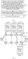
- Fig. 5 is a schematic view of a first flow chart of a node protection method provided by an embodiment of the present application applied to any node in an SRv6 network, such as any device of PE1 to PE4 and P1 to P4 in Fig. 4 .
- the node protection method includes:
- a preset flag bit is added to an SRH extension header by means of which it is indicated that the SRH extension header carries a backup SID.
- the SID of a backup tail node is added to an SID list contained in the SRH extension header. Based on the preset flag bit and the SID of the backup tail node contained in the SID list, in the event that the primary tail node is unreachable but the backup tail node is reachable, the first node can send the first service packet to the backup tail node for the back tail node to send the first service packet to a destination device corresponding to the original packet.
- the first service packet can be any SRv6 packet transmitted in a network.
- the first service packet contains an IPv6 basic header and an SRH extension header.
- the SRH extension header contains an SID list and a preset flag bit.
- the SRH extension header contained in the first service packet below is referred to as the first SRH extension header
- the SID list contained in the first SRH extension header is referred to as the first SID list.
- the preset flag bit contained in the first SRH extension header is referred to as the first value indicating that the SRH extension header carries the backup SID, which is the SID of the backup tail node.
- the first value can be 1 or 0.
- the primary SID is the SID of the primary tail node.
- the first service packet can be a service packet received by a first node, or a service packet obtained after the first node performs destination address updating or SRv6 encapsulation processing on a received service packet, which is not limited here.
- the first node After the first node obtains the first service packet, it executes block S52 of forwarding the first service packet.
- the preset flag bit can be used to indicate that the SRH extension header carries a backup SID, or the preset flag bit indicates that the SRH extension header does not carry a backup SID.
- the SID encapsulated in the second last element contained in the SID list is the primary SID
- the SID encapsulated in the last element is the backup SID.
- Segment List[0] is the backup SID, i.e., the SID encapsulated in the last element is the SID of the backup tail node
- Segment List[1]- Segment List[n] are nodes on the primary path arranged in the order from far to near.
- Segment List[1] is the primary SID, i.e., the SID encapsulated in the second last element is the SID of the primary tail node.
- the initial value of SL in the SRH extension header is n
- the value of Last Entry is n.
- the SID encapsulated in the last element contained in the SID list is the primary SID.
- Segment List[0]- Segment List[n-1] are nodes on the primary path arranged in the order from far to near.
- Segment List[0] is the primary SID, i.e., the SID encapsulated in the last element is the SID of the primary tail node.
- the initial value of SL in the SRH extension header is n-1, the value of Last Entry being n-1.
- the preset flag bit is set to a second value
- the SID list does not contain the backup SID.
- the SID of the backup tail node is encapsulated in the last element without the need to expand the routing protocol of the control plane.
- the SID of the backup tail node is encapsulated in the last element without the need to expand the routing protocol of the control plane.
- the first node can determine whether the preset flag bit indicates that the SRH extension header carries a backup SID or that the SRH extension header does not carry a backup SID based on whether the preset flag bit is set.
- the preset flag bit indicates that the SRH extension header carries a backup SID.
- the preset flag bit needs to occupy only one bit, which reduces network resource consumption.
- the preset flag bit can occupy a flag bit in the Flags field contained in the SRH extension header.
- a flag bit in the Flags field is the preset flag bit.
- B represents the preset flag bit.
- the preset flag bit in Fig. 7 occupies bit[4] in the 8 bits contained in the Flags field, which is not limiting (i.e., the preset flag bit can occupy any unoccupied flag of bit[0]-bit[7] contained in the Flags field.
- the first node can be a source node, endpoint node, or relay node on the primary path.
- an embodiment of the present application further provides a node protection method, which can include:
- an original packet is encapsulated as a first service packet so that the SID list contained in the first service packet has a primary SID and a backup SID, and a preset flag bit is set to a first value indicating that the SRH extension header carries a backup SID, which ensures subsequent correct processing of the first service packet.
- the original packet can be any packet transmitted in a network.
- the original packet can be an SRv6 packet, an IPv4 packet, or an IPv6 packet, which is not limited here.
- a source node After a source node receives an original packet sent by a CE device, it can extract a packet feature of the original packet.
- the packet feature can include, but is not limited to, information such as five-tuple, incoming interface, and service type, which is not limited here.
- the source node matches the extracted packet feature with a pre-stored feature of a packet forwarded on an SR path. If the extracted packet feature is matched with the pre-stored feature of the packet forwarded on the SR path, then it can be determined that the original packet is a service packet that needs to be forwarded on the SR path. In other words, the original packet is a service packet that needs to be forwarded on the primary path.
- the source node executes block S82.
- the source node can judge whether the primary SID of the primary tail node has a backup SID, i.e., whether the primary tail node has a backup tail node, based on learned routing information.
- the source node encapsulates an IPv6 basic header and an SRH extension header at an outer layer of the original packet, to obtain a first service packet.
- the structure of the first service packet one can refer to the relevant description of block S51, Fig. 6a , and Fig. 7 .
- the first service packet further contains an IPv6 basic header.
- the source node can forward the first service packet based on the behavior type of the destination address in the IPv6 basic header.
- the source node can determine the outgoing interface corresponding to the destination address in the IPv6 basic header, and sends the first service packet to the node of the next hop via the determined outgoing interface. If the behavior type of the destination address in the IPv6 basic header is End type, the source code can use the destination address in the IPv6 basic header to look up a forwarding table, and send the first service packet to the node of the next hop based on the results of the look-up of the forwarding table.
- Fig. 9 is a schematic view of a third flow chart of a node protection method provided by an embodiment of the present application applied to a first node, the method can include:
- the above-described blocks S91 to S93 are identical to the above-described blocks S81 to S83.
- the original packet is encapsulated as a common service packet so that the SID list contained in the common service packet has a primary SID but does not contain a backup SID, and a preset flag bit is set to a second value indicating that the SRH extension header does not carry a backup SID, ensuring subsequent correct processing of the common service packet.
- the source node by means of the preset flag bit and the detection of whether the primary tail node has a backup tail node, the source node supports at the same time packet forwarding in non-multi-homing scenarios and multi-homing scenarios, which enlarges the application scope of the technical solution provided by the embodiment of the present application.
- the source node judges whether the primary SID of the primary tail node has a backup SID based on learned routing information. In other words, it judges whether the primary tail node has a backup tail node. In the event that the primary SID does not have a backup SID, i.e., the primary tail node does not have a backup tail node, the source code executes block S94 of encapsulating an IPv6 basic header and an SRH extension header in an outer layer of the original packet, to obtain a common service packet. Regarding the structure of a common service packet, one can refer to the relevant description of Fig. 6b and Fig. 7 . In the embodiment of the present application, a common service packet is a service packet whose preset flag bit is set to a second value.
- the common service packet further contains an IPv6 basic header.
- the source code can forward the common service packet based on the behavior type of the destination address in the IPv6 basic header.
- the source node can determine the outgoing interface corresponding to the destination address in the IPv6 basic header, and send the common service packet to the node of the next hop via the determined outgoing interface. If the behavior type of the destination address in the IPv6 basic header is End type, the source code can use the destination address in the IPv6 basic header to look up a forwarding table, and send the common service packet to the node of the next hop based on the results of the look-up of the forwarding table.
- an embodiment of the present application further provides a node protection method, which can include:
- the first service packet can be send to a reachable primary tail node or backup tail node based on a node status of the primary tail node and the node status of the backup tail node, thus increasing network reliability.
- the second node can be a source node, or an endpoint node or relay node.
- the first node can be an endpoint node or relay node on an SRv6 Traffic Engineering (TE) path, or a relay node on an SRv6 Best-effort (BE) path.
- the second service packet is a first service packet sent by a second node.
- the first node receives a service packet sent by the second node, i.e., a second service packet.
- a service packet i.e., a second service packet.
- the structure of the second service packet one can refer to the relevant description of the structure of the first service packet.
- the SRH extension header contained in the second service packet is referred to as the second SRH extension header
- the IPv6 basic header contained in the second service packet is referred to as the first IPv6 basic header
- the SID list contained in the second SRH extension header is referred to as the second SID list.
- a node status can be reachable or unreachable.
- the first node can determine whether to use the primary tail node or the backup tail node as the tail node for forwarding a packet, based on the node status of the primary tail node and the node status of the backup tail node.
- the node status of the primary tail node and the node status of the backup tail node can be recorded in a forwarding table or a routing table.
- the first node can obtain the node status of the primary tail node and the node status of the backup tail node from the forwarding table or the routing table.
- the first node can accurately update the destination address in the IPv6 basic header to the SID of a reachable tail node based on the node status of the primary tail node and the node status of the backup tail node, which ensures that the first service packet can be forwarded to a destination CE device and increases network reliability.
- any of the following modes can be adopted to execute the above-described block S012 based on the first node's role on the primary path:
- the node status of the primary tail node is reachable, i.e., the primary tail node is reachable, in the event that the first node is a relay node, there is no need to update the destination address of the first IPv6 basic header.
- the destination address of the first IPv6 basic header can be directly used to look up a forwarding table, and the second service packet can be forwarded based on the result of the look-up of the forwarding table.
- the first node can also detect the mode of connection between the first node and the primary tail node and thus update the destination address in the first IPv6 basic header based on the mode of connection between the first node and the primary tail node, the node status of the primary tail node, and the node status of the backup tail node and the second SID list, to obtain a first service packet.
- the mode of connection can be direct connection or indirect connection.
- the first node can determine whether the first node is the node of the second last hop on the primary path based on the mode of connection between the first node and the primary tail node.
- the node of the second last hop can be an endpoint node or a relay node.
- the mode of connection between the first node and the primary tail node can be recorded in a forwarding table or a routing table.
- the first node can obtain the mode of connection between the first node and the primary tail node from the forwarding table or the routing table.
- any of the following modes can be adopted to execute the above-described block S102 based on the role of the first node on the primary path: Mode one, if the mode of connection between the first node and the primary tail node is direct connection, and the node status of the primary tail node is unreachable but the node status of the backup tail node is reachable, i.e., the first node is directly connected with the primary tail node and the primary tail node is unreachable but the tail node is reachable, updating the destination address in the first IPv6 basic header to the backup SID, to obtain a first service packet;
- the first node being directly connected with the primary tail node means that the first node is the node of the second last hop on the primary path. If the destination address in the first IPv6 basic header of the second service packet is the SID of the first node, the node of the second last hop can be an endpoint node; if the destination address in the first IPv6 basic header of the second service packet is not the SID of the first node, the node of the second last hop can also be a relay node.
- SRH extension header For example, the structure of an SRH extension header is as shown in Fig. 6a .
- the node of the second last hop is a relay node
- Mode two if the mode of connection between the first node and the primary tail node is direction connection, and the node status of the primary tail node is reachable, i.e., the first node is directly connected with the primary tail node and the primary tail node is reachable, in the event that the first node is an endpoint node, updating the destination address of the first IPv6 basic header to the primary SID, to obtain a first service packet; in the event that the first node is a relay node, directly forwarding the second service packet.
- the mode of connection between the first node and the primary tail node being direct connection means that the first node is the node of the second last hop on the primary path.
- the node of the second last hop can be an endpoint node or a relay node.
- the structure of the SRH extension header is as shown in Fig. 6a .
- the node of the second last hop is an endpoint node
- the node of the second last hop is a relay node
- Mode three if the mode of connection between the first node and the primary tail node is indirect connection, i.e., the first node is not directly connected with the primary tail node, then in the event that the first node is an endpoint node, updating the destination address of the first IPv6 basic header to the SID of the node of the next hop based on the second SID list, to obtain a first service packet; in the event that the first node is a relay node, directly forwarding the second service packet.
- the mode of connection between the first node and the primary tail node being indirect connection means that the first node is a node that is not the node of the second last hop other than a source node and a tail node on the primary path.
- a node that is not the node of the second last hop can be an endpoint node or a relay node.
- the first node can update the destination address of the first IPv6 basic header, to obtain a first service packet, by means of device B or device C in Fig. 3 .
- the first node is a relay node
- in the second SRH extension header, SL 4; after the first node receives the second service packet, it uses the destination address in the IPv6 basic header of the second service packet to look up a forwarding table, and forwards the second service packet to the node of the next hop based on the result of the look-up of the forwarding table.
- the mode of connection between the first node and the primary tail node achieves the replacement of the primary tail node and the backup tail node at the node of the second last hop on the primary path.
- the routing protocol of a control plane and to modify a small part of the processing of a data forwarding plane, for example, reducing SL by 1 based on an existing SRv6 forwarding mode at the node of the second last hop on the primary path, which achieves rapid path switching and increases network reliability.
- the first node forwards the first service node based on the behavior type of the destination address in the IPv6 basic header.
- the first node uses the destination address in the IPv6 basic header to look up a forwarding table and forwards the first service packet to the node of the next hop based on the result of the look-up of the forwarding table.
- the first node can receive a common service packet sent by a second node, the common service packet containing an IPv6 basic header and an SRH extension header, the SRH extension header containing a preset flag bit, the preset flag bit being set to a second value indicating that the SRH extension header does not carry a backup SID; update the destination address in the IPv6 basic header of the common service packet based on an SID list contained in the common service packet and forward the common service packet with the updated destination address.
- the common service packet is a service packet sent by the second node.
- the first node receives the common service packet sent by the second node.
- the structure of the common service packet one can refer to the relevant description above.
- the first node After receiving the common service packet, the first node updates the destination address in the IPv6 basic header of the common service packet based on its own role in combination with the SID list contained in the common service packet, and forwards the common service packet obtained after the update.
- an embodiment of the present application further provides a node protection method, which can include:
- de-encapsulating processing of the first service packet by the primary tail node or the backup tail node is supported.
- the IPv6 basic header and the SRH extension header encapsulated at an outer encapsulation of the first service packet is stripped off, so that in the event that the primary tail node is reachable, the primary tail node is responsible for forwarding the original packet to a destination CE device; in the event that the primary tail node is unreachable, the backup tail node is responsible for forwarding the original packet to the destination CE device, which ensures tail node reliability and increases network reliability, while at the same time increasing the node protection method's flexibility.
- the first node determines itself as the primary tail node or the backup tail node, the first node performs de-encapsulating processing on the first service packet, to obtain the original packet, and then looks up a forwarding table based on the destination address of the original packet and forwards the original packet to a destination CE device based on the result of the look-up of the forwarding table.
- the structure of the SRH extension header is as shown in Fig. 6a .
- the first node can determine itself as the primary tail node and then perform de-encapsulating processing on the first service packet, obtain the original packet, and forward the original packet.
- the first node can determine itself as the backup tail node and then perform de-encapsulating processing on the first service packet, obtain the original packet, and forward the original packet.
- Fig. 12 contains CE1 to CE2, PE1 to PE4, and P1 to P4.
- the Locator prefix of PE1 is A0::/64
- the Locator prefix of P1 is A1::/64
- P2 has a Locator prefix of A2::/64 and SID A2::1 of END.X type
- PE3 has a Locator prefix of A3::/64 and VPN SID A3::100
- PE4 has a Locator prefix of A4::/64 and VPN SID A4::100.
- PE3 In the event that PE3 is normal, traffic from CE1 to CE2 is forwarded along a primary path of PE1->P1->P2->PE3. After configuration is completed, PE1 determines a backup path of PE1->P1->P2->P4->PE4 by means of a routing optimization strategy, the backup SID of PE3 being VPN SID A4:: 100 of PE4.
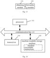
- an embodiment of the present application also provides a node protection device, as shown in Fig. 13 , the above node protection device is applied to a first node, comprising:
- the obtaining module 131 is specifically to:
- the obtaining module 131 is specifically to:
- the obtaining module 131 is specifically to:
- the obtaining module 131 is specifically to:
- the forwarding module 132 is specifically to strip off the outer encapsulation of the first service packet, to obtain an original packet; forward the original packet.
- the preset flag bit is set to a first value, the SID encapsulated in the second last element contained in the first SID list is the primary SID, and the SID encapsulated in the last element is the backup SID; the preset flag bit is set to a second bit, and the SID encapsulated in the last element contained in the first SID list is the primary SID.
- the first value is 1 or 0.
- the first SRH extension header further contains Flags field in which a flag bit is the preset flag bit.
- a preset flag bit is added to an SRH extension header by means of which it is indicated that the SRH extension header carries a backup SID.
- the SID of a backup tail node is added to an SID list contained in the SRH extension header. Based on the preset flag bit and the SID of the backup tail node contained in the SID list, in the event that the primary tail node is unreachable but the backup tail node is reachable, the first node can send the first service packet to the backup tail node for the back tail node to send the first service packet to a destination device corresponding to the original packet.
- an embodiment of the present application also provides an electronic equipment, which can be the first node, as shown in Fig. 14 , the electronic equipment includes: a processor 141, a machine readable storage medium142 and a transceiver 144.
- the machine readable storage medium 142 stores machine executable instructions capable of being executed by the processor 141; the machine executable instructions cause the processor 141 to execute the following blocks of:
- the machine executable instructions specifically cause the processor 141 to execute the following blocks of:
- the machine executable instructions specifically cause the processor 141 to execute the following blocks of:
- machine executable instructions specifically cause the processor to execute the following blocks of:
- machine executable instructions specifically cause the processor to execute the following blocks of:
- the machine executable instructions specifically cause the processor to execute the following blocks of: stripping off the outer encapsulation of the first service packet, to obtain an original packet; forwarding the original packet.
- the preset flag bit is set to a first value, the SID encapsulated in the second last element contained in the first SID list is the primary SID, and the SID encapsulated in the last element is the backup SID; the preset flag bit is set to a second bit, and the SID encapsulated in the last element contained in the first SID list is the primary SID.
- the first value is 1 or 0.
- the first SRH extension header further contains Flags field in which a flag bit is the preset flag bit.
- a preset flag bit is added to an SRH extension header by means of which it is indicated that the SRH extension header carries a backup SID.
- the SID of a backup tail node is added to an SID list contained in the SRH extension header. Based on the preset flag bit and the SID of the backup tail node contained in the SID list, in the event that the primary tail node is unreachable but the backup tail node is reachable, the first node can send the first service packet to the backup tail node for the back tail node to send the first service packet to a destination device corresponding to the original packet.
- the electronic equipment may also comprise a communication bus 143 .
- the processor 141, the machine-readable storage medium 142, and the transceiver 144 communicate with each other through the communication bus 143.
- the communication bus 143 can be a peripheral component interconnect standard (PCI) bus or an extended industry standard structure (EISA) bus, etc.
- the communication bus 1003 can be divided into address bus, data bus, control bus and so on.
- the transceiver 144 may be a wireless communication module, and the transceiver 144 performs data interaction with other equipment under the control of the processor 141.
- the machine-readable storage medium 142 may include a random access memory (RAM), and may also include a non-volatile memory (NVM), such as at least one magnetic disk memory.
- NVM non-volatile memory
- the machine-readable storage medium 142 may also be at least one storage device located away from the aforementioned processor.
- the processor 141 can be a general-purpose processor, including a central processing unit (CPU), a network processor (NP), and the like; it can also be a digital signal processor (DSP), an application-specific integrated circuit (ASIC), Field-Programmable Gate Array (FPGA) or other programmable logic devices, discrete gate or transistor logic devices, discrete hardware components.
- CPU central processing unit
- NP network processor
- DSP digital signal processor
- ASIC application-specific integrated circuit
- FPGA Field-Programmable Gate Array
- a machine-readable storage medium stores machine executable instructions that can be executed by a processor. When called and executed by a processor, the machine executable instructions cause the processor to execute the methods of any of the node protection methods described above.
- a computer program product including instructions is also provided, and when it is run on a computer, it causes the computer to execute the methods of any node protection method in the above embodiments.
- each embodiment in this specification is described in a related manner, the same and similar parts of each embodiment can be referred to each other, and each embodiment focuses on the differences from other embodiments.
- the description is relatively simple. For relevant information, reference can be made to the part of the description of the embodiment of the node protection method.
Landscapes
- Engineering & Computer Science (AREA)
- Computer Networks & Wireless Communication (AREA)
- Signal Processing (AREA)
- Data Exchanges In Wide-Area Networks (AREA)
Applications Claiming Priority (1)
| Application Number | Priority Date | Filing Date | Title |
|---|---|---|---|
| PCT/CN2022/130582 WO2024098244A1 (zh) | 2022-11-08 | 2022-11-08 | 一种节点保护方法、装置、电子设备及介质 |
Publications (2)
| Publication Number | Publication Date |
|---|---|
| EP4425879A1 true EP4425879A1 (de) | 2024-09-04 |
| EP4425879A4 EP4425879A4 (de) | 2025-01-01 |
Family
ID=91031727
Family Applications (1)
| Application Number | Title | Priority Date | Filing Date |
|---|---|---|---|
| EP22964720.1A Pending EP4425879A4 (de) | 2022-11-08 | 2022-11-08 | Knotenschutzverfahren und -vorrichtung, elektronische vorrichtung und medium |
Country Status (5)
| Country | Link |
|---|---|
| US (1) | US20250260640A1 (de) |
| EP (1) | EP4425879A4 (de) |
| JP (1) | JP2024545521A (de) |
| CN (1) | CN118318428A (de) |
| WO (1) | WO2024098244A1 (de) |
Family Cites Families (9)
| Publication number | Priority date | Publication date | Assignee | Title |
|---|---|---|---|---|
| US9444677B2 (en) * | 2013-10-18 | 2016-09-13 | Cisco Technology, Inc. | Scalable edge node protection using IPv6 segment routing extension header |
| WO2020072079A1 (en) * | 2018-10-05 | 2020-04-09 | Cisco Technology, Inc. | CROSS-DOMAIN CONTROL PLANE COLLABORATION FOR END-TO-END SRv6 SLA CONSTRAINED SERVICE DELIVERY |
| CN111698152B (zh) * | 2019-03-15 | 2021-09-14 | 华为技术有限公司 | 一种故障保护方法、节点及存储介质 |
| CN112825509B (zh) * | 2019-11-21 | 2024-04-16 | 华为技术有限公司 | 一种路径切换方法及相关装置 |
| CN113162849B (zh) * | 2020-01-22 | 2025-01-10 | 华为技术有限公司 | 一种报文处理方法、装置及系统 |
| US12348361B2 (en) * | 2020-06-30 | 2025-07-01 | New H3C Technologies Co., Ltd. | Method and apparatus for failure detection and PE device |
| CN114531395B (zh) * | 2020-11-23 | 2023-06-16 | 华为技术有限公司 | 一种通告网络设备处理能力的方法、设备和系统 |
| CN112822100B (zh) * | 2021-02-05 | 2026-04-28 | 中兴通讯股份有限公司 | 故障保护方法及装置、存储介质、电子装置 |
| CN113472658B (zh) * | 2021-06-29 | 2022-11-18 | 新华三信息安全技术有限公司 | 一种报文封装方法、报文转发方法及装置 |
-
2022
- 2022-11-08 CN CN202280004085.3A patent/CN118318428A/zh active Pending
- 2022-11-08 EP EP22964720.1A patent/EP4425879A4/de active Pending
- 2022-11-08 WO PCT/CN2022/130582 patent/WO2024098244A1/zh not_active Ceased
- 2022-11-08 US US18/714,953 patent/US20250260640A1/en active Pending
- 2022-11-08 JP JP2024536035A patent/JP2024545521A/ja active Pending
Also Published As
| Publication number | Publication date |
|---|---|
| WO2024098244A1 (zh) | 2024-05-16 |
| US20250260640A1 (en) | 2025-08-14 |
| CN118318428A (zh) | 2024-07-09 |
| JP2024545521A (ja) | 2024-12-09 |
| EP4425879A4 (de) | 2025-01-01 |
Similar Documents
| Publication | Publication Date | Title |
|---|---|---|
| KR102753139B1 (ko) | Sr 네트워크에서 패킷을 전달하는 방법, 장치 및 시스템 | |
| US12166667B2 (en) | Packet processing method, apparatus, and system | |
| US20220191138A1 (en) | Method for Making Host Network Performance Requirement Programmable, Device, and System | |
| KR20210102107A (ko) | 하이브리드 네트워크에서 패킷을 포워딩하기 위한 방법, 디바이스, 및 시스템 | |
| EP4099648A1 (de) | Verfahren zum verarbeiten von segment-id und vorrichtung | |
| US12537760B2 (en) | Packet forwarding method and apparatus, network device, and storage medium | |
| CN115277526B (zh) | 一种通信方法及装置 | |
| CN112769738A (zh) | DetNet数据包处理方法及装置 | |
| CN115550252A (zh) | 路由发布和转发报文的方法、装置、设备和存储介质 | |
| WO2022007550A1 (zh) | 一种负载均衡方法、装置、网络设备及系统 | |
| WO2023088145A1 (zh) | 一种报文处理方法、装置及设备 | |
| CN113395206A (zh) | 路由确定方法、装置和网络设备 | |
| EP4092978B1 (de) | Verfahren und gerät zur wahl eines bestimmten weiterleiters | |
| EP4425879A1 (de) | Knotenschutzverfahren und -vorrichtung, elektronische vorrichtung und medium | |
| EP4425840A1 (de) | Knotenschutzverfahren und -vorrichtung, elektrische vorrichtung und medium | |
| CN117097818A (zh) | 一种报文处理的方法及相关设备 | |
| EP4625937A1 (de) | Nachrichtenweiterleitungsverfahren und -vorrichtung sowie elektronische vorrichtung und speichermedium | |
| CN106656786B (zh) | 一种流量保护方法及装置 | |
| CN115460138B (zh) | 网络互通方法及装置 | |
| CN115460139B (zh) | 网络互通方法及装置 | |
| CN115460140B (zh) | 网络互通方法及装置 | |
| CN115460141B (zh) | 网络互通方法及装置 | |
| CN120416124A (zh) | 一种路由扩展头的源路由方法、通信节点和存储介质 | |
| WO2024198757A1 (zh) | 服务提供方法、装置、及存储介质 | |
| WO2024174668A1 (zh) | 一种信息传输方法及相关设备 |
Legal Events
| Date | Code | Title | Description |
|---|---|---|---|
| STAA | Information on the status of an ep patent application or granted ep patent |
Free format text: STATUS: THE INTERNATIONAL PUBLICATION HAS BEEN MADE |
|
| PUAI | Public reference made under article 153(3) epc to a published international application that has entered the european phase |
Free format text: ORIGINAL CODE: 0009012 |
|
| STAA | Information on the status of an ep patent application or granted ep patent |
Free format text: STATUS: REQUEST FOR EXAMINATION WAS MADE |
|
| 17P | Request for examination filed |
Effective date: 20240529 |
|
| AK | Designated contracting states |
Kind code of ref document: A1 Designated state(s): AL AT BE BG CH CY CZ DE DK EE ES FI FR GB GR HR HU IE IS IT LI LT LU LV MC ME MK MT NL NO PL PT RO RS SE SI SK SM TR |
|
| A4 | Supplementary search report drawn up and despatched |
Effective date: 20241204 |
|
| RIC1 | Information provided on ipc code assigned before grant |
Ipc: H04L 45/50 20220101ALI20241128BHEP Ipc: H04L 45/28 20220101ALI20241128BHEP Ipc: H04L 45/00 20220101ALI20241128BHEP Ipc: H04L 45/247 20220101AFI20241128BHEP |
|
| DAV | Request for validation of the european patent (deleted) | ||
| DAX | Request for extension of the european patent (deleted) |