EP4425852A1 - Nachrichtenübertragung - Google Patents
Nachrichtenübertragung Download PDFInfo
- Publication number
- EP4425852A1 EP4425852A1 EP22948263.3A EP22948263A EP4425852A1 EP 4425852 A1 EP4425852 A1 EP 4425852A1 EP 22948263 A EP22948263 A EP 22948263A EP 4425852 A1 EP4425852 A1 EP 4425852A1
- Authority
- EP
- European Patent Office
- Prior art keywords
- service message
- service
- message
- flow detection
- network device
- Prior art date
- Legal status (The legal status is an assumption and is not a legal conclusion. Google has not performed a legal analysis and makes no representation as to the accuracy of the status listed.)
- Pending
Links
Images


Classifications
-
- H—ELECTRICITY
- H04—ELECTRIC COMMUNICATION TECHNIQUE
- H04L—TRANSMISSION OF DIGITAL INFORMATION, e.g. TELEGRAPHIC COMMUNICATION
- H04L12/00—Data switching networks
- H04L12/28—Data switching networks characterised by path configuration, e.g. LAN [Local Area Networks] or WAN [Wide Area Networks]
- H04L12/46—Interconnection of networks
-
- H—ELECTRICITY
- H04—ELECTRIC COMMUNICATION TECHNIQUE
- H04L—TRANSMISSION OF DIGITAL INFORMATION, e.g. TELEGRAPHIC COMMUNICATION
- H04L45/00—Routing or path finding of packets in data switching networks
- H04L45/74—Address processing for routing
-
- H—ELECTRICITY
- H04—ELECTRIC COMMUNICATION TECHNIQUE
- H04L—TRANSMISSION OF DIGITAL INFORMATION, e.g. TELEGRAPHIC COMMUNICATION
- H04L43/00—Arrangements for monitoring or testing data switching networks
- H04L43/10—Active monitoring, e.g. heartbeat, ping or trace-route
-
- H—ELECTRICITY
- H04—ELECTRIC COMMUNICATION TECHNIQUE
- H04L—TRANSMISSION OF DIGITAL INFORMATION, e.g. TELEGRAPHIC COMMUNICATION
- H04L45/00—Routing or path finding of packets in data switching networks
- H04L45/02—Topology update or discovery
- H04L45/036—Updating the topology between route computation elements, e.g. between OpenFlow controllers
- H04L45/037—Routes obligatorily traversing service-related nodes
-
- H—ELECTRICITY
- H04—ELECTRIC COMMUNICATION TECHNIQUE
- H04L—TRANSMISSION OF DIGITAL INFORMATION, e.g. TELEGRAPHIC COMMUNICATION
- H04L45/00—Routing or path finding of packets in data switching networks
- H04L45/34—Source routing
-
- H—ELECTRICITY
- H04—ELECTRIC COMMUNICATION TECHNIQUE
- H04L—TRANSMISSION OF DIGITAL INFORMATION, e.g. TELEGRAPHIC COMMUNICATION
- H04L45/00—Routing or path finding of packets in data switching networks
- H04L45/50—Routing or path finding of packets in data switching networks using label swapping, e.g. multi-protocol label switch [MPLS]
-
- H—ELECTRICITY
- H04—ELECTRIC COMMUNICATION TECHNIQUE
- H04L—TRANSMISSION OF DIGITAL INFORMATION, e.g. TELEGRAPHIC COMMUNICATION
- H04L45/00—Routing or path finding of packets in data switching networks
- H04L45/76—Routing in software-defined topologies, e.g. routing between virtual machines
-
- H—ELECTRICITY
- H04—ELECTRIC COMMUNICATION TECHNIQUE
- H04L—TRANSMISSION OF DIGITAL INFORMATION, e.g. TELEGRAPHIC COMMUNICATION
- H04L69/00—Network arrangements, protocols or services independent of the application payload and not provided for in the other groups of this subclass
- H04L69/22—Parsing or analysis of headers
Definitions
- the present disclosure relates to the technical field of communications, and in particular, to message sending.
- a head node After receiving a service message, a head node can encapsulate a Segment Routing Header (SRH) in an outer layer of the service message.
- An Segment List is contained in the SRH.
- the Segment List indicates a forwarding path of the service message in the SRv6 network, thus, nodes in the SRv6 network can forward the service message based on the forwarding path.
- a head node can also add an in-situ flow detection option to a service message.
- various nodes on a forwarding path can perform in-situ flow detection on the service message based on the in-situ flow detection option, and periodically report measurement information to an analyzer, and then the analyzer can determine the network performance of the forwarding path based on the measurement information.
- the in-situ flow detection option can contain mark bits, for example a delay mark bit indicating whether to perform delay detection, and a loss mark bit indicating whether to perform loss detection.
- an SRv6 network can be combined with a service chain function. Based on actual service requirements, some endpoint nodes in the SRv6 network can serve as Service Function Forwarder (SFF) nodes which are connected with Service Function (SF) nodes. If the type of a SFF node is End.AD or End.AS, then after receiving a service message, the SFF node needs to delete the IPv6 header, in-situ flow detection option, and SRH encapsulated in the outer layer of the service message, and send the original service message to SF. After the SF node completes processing, it forwards the processed original service message to the SFF node.
- SFF Service Function Forwarder
- the SFF node encapsulates an IPv6 header, in-situ flow detection option, and SRH for the original service message based on its static configuration information or dynamic cache, wherein, the static configuration information includes pre-configured information for encapsulating the IPv6 header and SRH, and the dynamic cache is information for encapsulating the IPv6 header and SRH learned by the SFF node based on the received message.
- the value of the mark bit added by the head node to different service messages will change dynamically with the number of service messages received by the head node.
- the value of the mark bit added by the head node to each service message cannot be determined in advance.
- the SFF node is unable to store the in-situ flow detection option based on the static configuration information or dynamic cache, and thus unable to detect the forwarding path based on the in-situ flow detection technology.
- the present disclosure aims at message sending, so as to perform a detection on a forwarding path based on an in-situ flow detection technology.
- the specific technical solutions are as follows.
- an example of the present disclosure provides a method for message sending, which is applied to a network device, the method includes:
- the method before sending the second service message on the forwarding path, the method further includes:
- the method before sending the first service message on the forwarding path, the method further includes:
- the method before sending a second service message on the forwarding path, the method further includes:
- obtaining a link state of a link between the network device and the service function node specifically includes:
- the in-situ flow detection option of the second service message includes a reserved field carrying the replication flag information.
- an example of the present disclosure provides an apparatus for message sending, which is applied to a network device, the apparatus includes:
- the apparatus further includes: a judging module and a replicating module;
- the apparatus further includes: a first discarding module
- the apparatus further includes: an obtaining module, a second discarding module, and a replicating module;
- the obtaining module is specifically to:
- the in-situ flow detection option of the second service message includes a reserved field carrying the replication flag information.
- an example of the present disclosure provides a network device comprising:
- machine executable instructions further cause the processor to execute the following steps:
- machine executable instructions further cause the processor to execute the following steps:
- machine executable instructions further cause the processor to execute the following steps:
- machine executable instructions further cause the processor to execute the following steps:
- the in-situ flow detection option of the second service message includes a reserved field carrying the replication flag information.
- an example of the present disclosure provides a machine-readable storage medium having stored thereon machine executable instructions that, when invoked and executed by a processor, cause the processor to execute the method described above in the first aspect.
- an example of the present disclosure provides a computer program product, which causes the processor to perform the method described above in the first aspect.
- a network device can send a second service message with a second in-situ flow detection option containing replication flag information on a forwarding path, so that the second service message will not be forwarded to a service function node, and thus there is no need to delete the in-situ flow detection option of the second service message before re-encapsulation, which allows various network devices on the forwarding path to receive the second service message carrying the in-situ flow detection option and perform in-situ flow detection.
- the network device can normally send an original message to a service function node, without affecting service processing of the service function node. It can be seen that examples of the present disclosure achieve the in-situ flow detection on a forwarding path without affecting service chain services.
- In-situ flow detection consists in using normally forwarded service flow, inserting an in-situ flow detection option in specified service flow, detecting the service flow carrying the in-situ flow detection option by means of a forwarding device, reporting the collected measurement information to an analyzer which then detects and identifies subtle anomalies in a network based on the received measurement information and precisely detects performance information such as delay and loss of each service, so that the network quality SLA is visible in real time and rapid delimitation and locating of a defect is achieved.
- the in-situ flow detection network comprises a head node, a plurality of intermediate nodes, and a tail node.
- FIG. 1a shows by way of example two intermediate nodes, which are intermediate node 1 and intermediate node 2, wherein the intermediate node 1 does not support in-situ flow detection while the intermediate node 2 supports in-situ flow detection.
- the head node is used for receiving an actual service flow. If it is determined that in-situ flow detection needs to be performed on the service flow, then measure data of the service flow is sent to an analyzer, an in-situ flow detection option is added to the service flow, and service flow carrying the in-situ flow detection option is forwarded to the intermediate node 1 connected with itself.
- the service flow is directly forwarded to the intermediate node 2.
- the intermediate node 2 is used for receiving a service flow. If it is identified that the service flow includes an in-situ flow detection option and the measure type indicated by the in-situ flow detection option is point-by-point measurement, then measurement data of the service flow is sent to the analyzer based on the in-situ flow detection option and the service flow is forwarded to the tail node. Or, if the measurement type indicated by the in-situ flow detection option is end-to-end measurement, then it is not necessary to send the measurement data to the analyzer, and the service flow can be forwarded to a tail node.
- the tail node is used for receiving a service flow. If it is identified that the service flow includes an in-situ flow detection option, then measurement data of the service flow is sent to the analyzer based on the in-situ flow detection option, the in-situ flow detection option is deleted from the service flow, and the service flow is in turn forwarded.
- the analyzer is used for receiving measurement data sent by the head node, the intermediate nodes, and the tail node, and assembling and calculating the received measurement data. For example, it can perform loss and delay calculations in order to obtain the quality of the path taken by the service flow.
- the head node of an SRv6 network serves the head node of in-situ flow detection at the same time.
- In-situ flow detection can be initiated by a controller or a command line on the head node.
- Information such as flow property, detected period, and type that needs to perform in-situ flow detection can be specified by ACL.
- the head node when receiving service flow that satisfies flow properties, inserts an in-situ flow detection option in the service flow.
- the in-situ flow detection option can be specifically carried by an IPv6 extension header, for example, a Hop-By-Hop option extension header, or a destination option extension header.
- PE1 is a head node of an SRv6 network.
- SRv6 SRv6 network.
- an IPv6 header, an in-situ flow detection option, and an SRH header are encapsulated in an outer layer of the original message.
- PE1 sends a message to P1, wherein, the IPv6 header includes a Source Address (SA) of 8000:: 1, and a Destination Address (DA) of A:A:A:A: 1:1::, i.e., the address of P 1.
- SA Source Address
- DA Destination Address
- An in-situ flow detection option includes: FlowMonID, which is the ID of a service flow detected.
- FlowNodeID which is the ID of the head node passed by a service flow, which can add its own node ID to this field when encapsulating an in-situ flow detection option in a service message.
- Header Type Indication which is used for indicating the carried extension data type.
- T which is used for indicating the detection type, including end-to-end detection and hop-by-hop detection.
- P, T, L, and D are mark bits.
- P1 does not support in-situ flow detection, therefore, after P1 receives the message, it updates the destination address of the message to A:A:A:A:2: 1::, i.e., the address of P2, and forwards the message to P2.
- P2 After P2 receives the message, it can identify the in-situ flow detection option contained in the message so as to perform in-situ flow detection on the message. P2 will also update the destination address of the message to A:A:A:A:20:6::, i.e., the address of PE2, and forward the message to PE2.
- PE2 After PE2 receives the message, it can identify the in-situ flow detection option contained in the message so as to perform in-situ flow detection on the message. As PE2 is the tail node, PE2 will delete the IPv6 header, the in-situ flow detection option, and the SRH from the message and then send the original message to CE2.
- PE1, P2, and PE2 when receiving and sending a message carrying an in-situ flow detection option, PE1, P2, and PE2 will count the data of the message (for example, a timestamp of receiving the message and a timestamp of sending the message) based on the in-situ flow detection option, and periodically report flow ID and measurement information to the analyzer.
- R1, R2, and R3 in FIG. 1b are processes of reporting the measurement information to the analyzer.
- in-situ flow detection can be performed on a service chain path based on the above described in-situ flow detection technology.
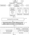
- FIG. 2 which is a schematic diagram of a scenario of combining an SRv6 network and a service chain.
- the SRv6 network in FIG. 2 can be a Generalized-SRv6 (G-SRv6) network, i.e., a compressed C-SID carried in an SRH. Or, it can be applied to a regular SRv6 network, i.e., an uncompressed C-SID carried in an SRH.
- G-SRv6 Generalized-SRv6
- regular SRv6 network i.e., an uncompressed C-SID carried in an SRH.
- the service chain path in the example of the present disclosure means that in a forwarding path (which means a path indicated by a Segment ID (SID) list), a path between a SFF node and an SF node is additionally added.
- SID Segment ID
- the forwarding path means: head node-SFF1-SFF2-SFF3;
- the service chain path means: head node-SFF1-SF1-SFF1-SFF2-SF2-SFF2-SFF3.
- the head node i.e., the Classifier in the scenario of a service chain function
- receives an original message OEM Packet
- it encapsulates an IPv6 header, an SRH, and an in-situ flow detection option in an outer layer of the original message to obtain an encapsulated message, and then sends the encapsulated message to SFF1.
- SFF1 deletes the IPv6 header, the SRH, and the in-situ flow detection option to obtain the original message, and then sends the original message to SF1.
- SFF1 After receiving the original message processed by SF1, SFF1 needs to re-encapsulate an IPv6 header, an SRH, and an in-situ flow detection option for the processed message.
- the SFF1 node As the in-situ flow detection option is marked flow by flow or message by message, the SFF1 node is unable to restore the in-situ flow detection option based on static configuration information or dynamic cache, which causes the SFF1 node to be able to only encapsulate an IPv6 header and an SRH for the processed original message and to send the message encapsulated with the IPv6 header and the SRH to SFF2.
- SFF2 also sends a message encapsulated with an IPv6 header and an SRH to SFF3.
- the SF node may perform deep analysis on the original message, which takes a relatively long time that may be far longer than the time of being transmitted along a forwarding path indicated by the SID list.
- the SF node may also lose the original message. Therefore, performing in-situ flow detection on the message processed by the SF node is unable to reflect the actual situation of the forwarding path indicated by the SID list and to perform accurate delay detection and loss detection for the forwarding path.
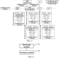
- an example of the present disclosure provides a method for message sending applied to a network device. As shown in FIG. 3 , the method includes the following blocks.
- the first service message includes a destination address, a first in-situ flow detection option, a first SRH and an original service message, and the SRH includes an SID list indicating a forwarding path.
- the first service message includes an IPv6 header
- the IPv6 header includes a destination address
- the second service message includes a second in-situ flow detection option, which includes replication flag information for indicating that the second service message is a replication message of the first service message.
- the network device can send the second service message on the forwarding path based on the SID list, and if the destination address is a locally configured proxy SID, then it means that the network device is connected with a service function node.
- the network device can delete the first in-situ flow detection option, the first SRH, and the IPv6 header encapsulated in the outer layer of the first service message, to obtain the original service message, and forward the original service message to the service function node.
- the network device When the service function node sends the processed original service message to a network device, the network device re-encapsulate an SRH and an IPv6 header for the received original service message based on the local static configuration information or dynamic cache information to obtain a third service message. Then, the network device can forward the third service message based on a forwarding path indicated by the SID list. In other words, the third service message will be forwarded by the network device to a next network device on a forwarding path indicated by the SID list in the SRH. Wherein, the third service message does not contain an in-situ flow detection option.
- the network device can be SFF1 in FIG. 2 .
- SFF1 receives a first service message and determines that the destination address is a locally configured proxy SID (specifically, it can be End.AS SID or End.AD SID), it then sends a second service message to SFF2 and sends the original service message contained in the first service message to SF1.
- SFF1 After receiving the processed original service message sent by SF1, SFF1 encapsulates an IPv6 header and an SRH header for the processed original service message, to obtain a third service message, and then sends the third service message to SFF2.
- SFF2 can receive the second service message and the third service message, and after SFF2 identifies the replication flag information included in the second in-situ flow detection option of the second service message, it will not send the second service message to SF2, and instead, it will continue to forward the second service message to SFF3 on the forwarding path.
- SFF2 can normally process the third service message.
- the network device after the network device receives a first service message, if a destination address of the first service message is a locally configured proxy SID, the network device sends a second service message on a forwarding path, and sends the original service message to a service function node.
- the in-situ flow detection option of the second service message includes replication flag information for indicating that the second service message is a replication message of the first service message.
- the network device sends the second service message including the second in-situ flow detection option on the forwarding path, so that the second service message will not be forwarded to a service function node, and thus there is no need to delete the in-situ flow detection option of the second service message before re-encapsulation, which allows various network devices on the forwarding path to receive the second service message carrying the in-situ flow detection option and perform in-situ flow detection.
- the network device can normally send an original message to a service function node, without affecting service processing of the service function node. It can be seen that example of the present disclosure achieves in-situ flow detection on a forwarding path without affecting services.
- the second service message does not need to be processed by a service function node, forwarding time is saved, and the second service message is avoided to be discarded by a service function node. Since the second service message is transmitted on the forwarding path and will not be forwarded to a service function node, various nodes on the forwarding path perform in-situ flow detection based on the second service message, which can accurately reflect network performance of the forwarding path and can perform accurate delay detection and loss detection for the forwarding path.
- the first in-situ flow detection option and the second in-situ flow detection option of the above described first service message both contain a reserved field.
- the reserved field of the second in-situ flow detection option carries replication flag information.
- FIG. 4 is a schematic diagram of an in-situ flow detection option provided by an example of the present disclosure.
- Option Type occupies 8 bits and is the type of the in-situ flow detection option.
- Opt Data Len occupies 8 bits and is the length of the in-situ flow detection option.
- FlowMonID occupies 20 bits and is the ID of a service flow detected.
- L occupies 1 bit and is a Loss flag.
- D occupies 1 bit and is a delay flag.
- Header Type Indication is used for indicating the type of extension data carried. When its value is 0, it indicates that there is no extension data. When its value is not 0, it indicates that extension data is carried.
- NodeMonID occupies 20 bits and is a device node identifier.
- a head node encapsulates an in-situ flow detection option in a service message, it can add its own node identifier in this field.
- F occupies 1 bit and is a service flow direction identifier field used for carrying second indicating information. When its value is 1, it indicates that a head node on a reverse path automatically generates a service flow identification rule. When its value is 0, it indicates that the head node of a first reverse path does not generate a service flow identification rule.
- the head node of the reverse path is the tail node of the forward forwarding path. Taking FIG. 1b as an example, the forward path is the path from PE1 to PE2, the reverse path is the path from PE2 to PE1, and PE2 in FIG. 1b is the tail node of the forward path and the head node of the reverse path at the same time.
- P is a measurement period
- T is used for indicating the detection type, which includes end-to-end detection and hop-by-hop detection.
- Ext FM Type is an extension flow detection type field and can be identified in the form of a bitmap.
- the replication flag information can be carried by any field of the reserved fields, such as R, Rsv, and Reserved in FIG. 4 , which is not limited by examples of the present disclosure.
- replication flag information can be carried in the R field located in the D field in FIG. 4 . If the replication flag is set, i.e., its value is 1, then it indicates that the message is a replication message; if the replication Flag is not set, i.e., its value is 0, then it indicates that the message is not a replication message.
- the first service message received by the network device may also be a replication message sent by a SFF node. Therefore, if the destination address of the first service message is a locally configured proxy SID, then the network device, before sending the second service message on the forwarding path, can determine whether the first in-situ flow detection option includes replication flag information; if yes, i.e., the first in-situ flow detection option includes replication flag information, then the first service message is sent on the forwarding path.
- the network device If the first in-situ flow detection option includes replication flag information, then it means that the first service message is obtained by replication, and the network device does not need to replicate the first service message anymore or perform relevant service chain processing on the first service message. It can perform in-situ flow detection based on the first in-situ flow detection option and send the first service message on the forwarding path.
- the first in-situ flow detection option does not include replication flag information
- the first service message is replicated and replication flag information is added to the in-situ flow detection option of the replicated first service message, to obtain a second service message. Then, the above-described S302 is executed.
- the network device obtains the second service message by replicating the first service message, and compared to the first service message, the second service message adds replication flag information to the in-situ flow detection option, and the other contents included in the second service message are the same as that in the first service message.
- the network device can update the destination address in the IPv6 header of the second service message to a next SID after the SID of the network device in the forwarding path.
- the network device can also determine whether the destination address is a last SID in the SID list, and if the destination address is the last SID in the SID list, the first service message is discarded, and if the destination address is not the last SID in the SID list, then the first service message is sent on the forwarding path according to the above-described method.
- the destination address is a last SID in the SID list, it means that the network device receiving the first service message is the tail node of the forwarding path.
- the first service message includes replication flag information, it indicates that the first service message is a service message obtained by replication for performing in-situ flow detection of the forwarding path, after the tail node receives the first service message, it means that the first service message has completed the transmission on the forwarding path, and in order to avoid affecting services, the tail node does not need to continue to send the first service message to a CE device.
- a network device after a network device receives a first service message, it can determine whether a first in-situ flow detection option of the first service message includes replication flag information.
- the first service message is forwarded on the forwarding path without the need to forwarding the first service message to a service function node and thus without the need to delete the in-situ flow detection option of the first service message before re-encapsulation, so that various network devices on the forwarding path can receive the first service message carrying the in-situ flow detection option and perform in-situ flow detection for the forwarding path based on the first service message.
- in-situ flow detection results can accurately reflect the quality of the forwarding path.
- the network device replicates the first service message and adds replication flag information in the replicate the replicate service message, to obtain a second service message, so that when a subsequent network device on the forwarding path receives the second service message, there is no need to forward the second service message to a service function node and thus there is no need to firstly delete the in-situ flow detection option of the second service message before re-encapsulation, so that various network devices on the forwarding path can all receive the second service message carrying the in-situ flow detection option and perform the in-situ flow detection option for the forwarding path based on the second service message, which solves the problem that in-situ flow detection cannot be performed on the forwarding path and allows in-situ flow detection results to accurately reflect the quality of the forwarding path.
- the network before the network device sends the second service message on the forwarding path, or in the case that the network device determines that the first in-situ flow detection option does not include replication flag information, then before sending the second service message on the forwarding path, the network can also obtain a link state of a link between the network device and a service function node.
- the network device can monitor in real time the link state of the link between the network device and a service function node and can record the link state in a data plane.
- the network device can obtain the link state of the link between the network device and a service function node from a data plane.
- the link state is inaccessible; if the service function node does not fail and the link between the network device and the service function node does not fail, the link state is accessible.
- the network device can determine whether a link between the network device and a service function node fails based on an interface state of an interface locally connected with the service function node. When the interface state is abnormal, it is determined that the link between the network device and the service function node fails; when the interface state is normal, it is determined that the link between the network device and the service function node does not fail.
- the network device can also determine the state of a link between the network device and a service function node by means of other methods in the prevent art, which is not limited by examples of the present disclosure.
- the forwarding switch between the network device and the service function node is set to be closed; if the service function node does not fail and the link between the network device and the service function node does not fail, then the forwarding switch between the network device and the service function node is set to be opened.
- the network device determines that the forwarding switch is in an open state, then it is determined that the link state is accessible; if the network device determines that the forwarding switch is in a closed state, then it is determined that the link state is inaccessible.
- the analyzer is unable to receive in-situ flow detection data reported based on the first service message by other network devices after the network device on the forwarding path, and thus it can be determined that the service chain path of the first service message fails.
- in-situ flow detection results of the analyzer can also reflect a defect of a link between the network device and a service function node.
- the analyzer timely triggers the head node to timely switch service chain paths so as to avoid affecting a service chain function for a long period of time.
- whether the first service message needs to be discarded in the event that it is determined that the link state is inaccessible can also be determined by instructing the network device by settings based on actual needs. For example, if there is no need to detect whether a link between the network device and a service function node fails by in-situ flow detection technology, then even if the state of the link between the network device and the SF mode is determined by the network device to be inaccessible, the network device still does not need to discard the first service message, and instead, can replicate the first service message and send the second service message on the forwarding path. Thus, in-situ flow detection of a subsequent forwarding path can be realized. In this situation, the head node can detect whether the state of a link between the network device and a service function node is accessible by another mode of detection in relevant art, which is not limited by examples of the present disclosure.
- the network device obtains a link state of a link between the network device and a service function node, determines whether the first service message needs to be discarded based on whether the link state is accessible, and if it is inaccessible, then the network device replicates the first service message, and generates a second service message, and transmits the second service message on the forwarding path, thus allowing in-situ flow detection of the forwarding path; if it is inaccessible, then the network device discards the first service message, so that the analyzer can timely discover that the service chain path fails, thus triggering the head node to timely switch service chain paths, avoiding affecting a service chain function for a long period of time.
- a head node After a head node receives an original service message, it encapsulates an IPv6 header, an in-situ flow detection option, and an SRH in an outer layer of the original service message, to obtain a first service message, and sends the first service message to SFF1.
- the destination address of the IPv6 header of the first service message is SFF1
- the Segment List included in the SRH is SFF1::SF1, SFF2::SF2, SFF3.
- SFF1 After receiving a first service message, SFF1 replicates the first service message, to obtain a second service message, adds replication flag information in the in-situ flow detection option of the second service message, and then sends the second service message on the forwarding path and sends the original service message to SF1.
- SFF1 After SFF1 receives the processed original service message sent by SF1, it encapsulates an SRH and an IPv6 header for the processed original service message, to obtain a third service message, and sends the third service message to SFF2.
- SFF2 can receive the second service message and the third service message.
- SFF2 identifies that the in-situ flow detection option included in the second service includes replication flag information, and then performs in-situ flow detection based on the in-situ flow detection option and forwards the second service message to SFF3.
- SFF2 can send the original service message in the third service message to SF2, and after receiving the original service message processed by SF2, it encapsulates an IPv6 header and an SRH header for the processed original service message, to obtain a fourth service message, and forwards the fourth service message to SFF3.
- SFF3 can receive the second service message and the fourth service message. As SFF3 is the tail node, SFF3 can send the original service message included in the fourth service message to a subsequent device (for example, a CE device) and discard the second service message.
- a subsequent device for example, a CE device
- the type of the SID of SFF1 and SFF3 can also be an End.AM type.
- SFF1 and SFF2 still send the second service message on the forwarding path according to the above-described method and process the first service message according to the processing mode of an End.AM type node.
- SFF1 After SFF1 receives a service message returned by SF1, it can continue to forward the message based on a mode specified by a protocol.
- no service function node will receive a service message carrying an in-situ flow detection option, and the demands on service function nodes will not be increased.
- an example of the present disclosure further provides an apparatus for message sending applied to a network device.
- the apparatus includes:
- the obtaining module is specifically to:
- the in-situ flow detection option of the second service message includes a reserved field carrying the replication flag information.
- the network device comprises: a processor 701; a transceiver 704; a machine-readable storage medium 702 which stores machine executable instructions that can be executed by the processor 701 and cause the processor 701 to implement the following steps:
- machine executable instructions further cause the processor 701 to execute the following steps:
- machine executable instructions further cause the processor 701 to execute the following steps:
- machine executable instructions further cause the processor 701 to execute the following steps:
- machine executable instructions further cause the processor 701 to execute the following steps:
- the in-situ flow detection option of the second service message includes a reserved field carrying the replication flag information.
- the network device can further include a communication bus 703.
- the processor 701, the machine-readable storage medium 702, and the transceiver 704 communicate with each other via the communication bus 703.
- the communication bus 703 may be a Peripheral Component Interconnect (PCI) bus or an Extended Industry Standard Architecture (EISA) bus, etc.
- PCI Peripheral Component Interconnect
- EISA Extended Industry Standard Architecture
- the communication bus 703 can be divided into an address bus, a data bus, a control bus, etc.
- the transceiver 704 can be a wireless communication module and can exchange data with other devices under the control of the processor 701.
- the machine-readable storage medium 702 may include Random Access Memory (RAM), and may also include Non-Volatile Memory (NVM), such as at least one disk storage. Additionally, the machine-readable storage medium 702 may also be at least one storage device located remotely from the above-mentioned processor.
- RAM Random Access Memory
- NVM Non-Volatile Memory
- the processor 701 may be a general-purpose processor, including a Central Processing Unit (CPU), a Network Processor (NP), etc.; it may also be a Digital Signal Processing (DSP), an Application Specific Integrated Circuit (ASIC), a Field-Programmable Gate Array(FPGA), or other programmable logic devices, discrete gate or transistor logic devices, discrete hardware components.
- CPU Central Processing Unit
- NP Network Processor
- DSP Digital Signal Processing
- ASIC Application Specific Integrated Circuit
- FPGA Field-Programmable Gate Array
- an example of the present disclosure further provides a machine-readable storage medium which stores machine executable instructions that can be executed by the processor and cause the processor to implement the steps of any of the method for message sending described above.
- a computer program product including instructions is also provided, which, when running on a computer, causes the computer to execute the method for message sending of any one of the above described examples.
Landscapes
- Engineering & Computer Science (AREA)
- Computer Networks & Wireless Communication (AREA)
- Signal Processing (AREA)
- Computer Security & Cryptography (AREA)
- Computing Systems (AREA)
- Theoretical Computer Science (AREA)
- Health & Medical Sciences (AREA)
- Cardiology (AREA)
- General Health & Medical Sciences (AREA)
- Data Exchanges In Wide-Area Networks (AREA)
- Telephonic Communication Services (AREA)
Applications Claiming Priority (1)
| Application Number | Priority Date | Filing Date | Title |
|---|---|---|---|
| PCT/CN2022/101725 WO2024000140A1 (zh) | 2022-06-28 | 2022-06-28 | 报文发送 |
Publications (2)
| Publication Number | Publication Date |
|---|---|
| EP4425852A1 true EP4425852A1 (de) | 2024-09-04 |
| EP4425852A4 EP4425852A4 (de) | 2025-02-19 |
Family
ID=89383689
Family Applications (1)
| Application Number | Title | Priority Date | Filing Date |
|---|---|---|---|
| EP22948263.3A Pending EP4425852A4 (de) | 2022-06-28 | 2022-06-28 | Nachrichtenübertragung |
Country Status (4)
| Country | Link |
|---|---|
| US (1) | US20250030634A1 (de) |
| EP (1) | EP4425852A4 (de) |
| CN (1) | CN117643019A (de) |
| WO (1) | WO2024000140A1 (de) |
Families Citing this family (2)
| Publication number | Priority date | Publication date | Assignee | Title |
|---|---|---|---|---|
| CN118827450A (zh) * | 2024-03-04 | 2024-10-22 | 中国移动通信有限公司研究院 | 随流检测信息的处理方法、装置、设备、介质和产品 |
| CN118101555B (zh) * | 2024-04-22 | 2024-07-23 | 新华三技术有限公司 | 报文转发方法、装置、电子设备及计算机可读存储介质 |
Family Cites Families (7)
| Publication number | Priority date | Publication date | Assignee | Title |
|---|---|---|---|---|
| WO2015136843A1 (ja) * | 2014-03-10 | 2015-09-17 | パナソニック インテレクチュアル プロパティ コーポレーション オブ アメリカ | 情報機器、管理サーバ及びコピー制御方法 |
| US10129127B2 (en) * | 2017-02-08 | 2018-11-13 | Nanning Fugui Precision Industrial Co., Ltd. | Software defined network controller, service function chaining system and trace tracking method |
| CN111953604B (zh) * | 2019-05-17 | 2023-07-18 | 华为技术有限公司 | 一种为业务流提供业务服务的方法和装置 |
| CN113079089B (zh) * | 2020-01-03 | 2025-01-07 | 华为技术有限公司 | 业务链的故障保护方法、装置、设备、系统及存储介质 |
| CN113079091B (zh) * | 2020-01-03 | 2022-07-22 | 华为技术有限公司 | 一种主动随流检测的方法、网络设备以及通信系统 |
| CN113556259B (zh) * | 2020-04-24 | 2024-04-12 | 华为技术有限公司 | 一种基于随流检测的报文处理方法及装置 |
| CN111865658B (zh) * | 2020-06-05 | 2022-06-07 | 烽火通信科技股份有限公司 | 基于vCPE多租户的租户业务识别映射方法及系统 |
-
2022
- 2022-06-28 US US18/714,687 patent/US20250030634A1/en active Pending
- 2022-06-28 WO PCT/CN2022/101725 patent/WO2024000140A1/zh not_active Ceased
- 2022-06-28 CN CN202280001942.4A patent/CN117643019A/zh active Pending
- 2022-06-28 EP EP22948263.3A patent/EP4425852A4/de active Pending
Also Published As
| Publication number | Publication date |
|---|---|
| CN117643019A (zh) | 2024-03-01 |
| WO2024000140A1 (zh) | 2024-01-04 |
| US20250030634A1 (en) | 2025-01-23 |
| EP4425852A4 (de) | 2025-02-19 |
Similar Documents
| Publication | Publication Date | Title |
|---|---|---|
| US6515967B1 (en) | Method and apparatus for detecting a fault in a multicast routing infrastructure | |
| EP4149058B1 (de) | Verfahren, vorrichtung, vorrichtung und system zur messung der netzwerkleistung und speichermedium | |
| CN111385121B (zh) | 一种操作管理维护iOAM报文的传输方法及相应装置 | |
| EP4425852A1 (de) | Nachrichtenübertragung | |
| US9124529B1 (en) | Methods and apparatus for assessing the quality of a data path including both layer-2 and layer-3 devices | |
| CN111585834B (zh) | 一种网络信息的存储方法和装置 | |
| WO2022062931A1 (zh) | 网络异常确定方法及装置 | |
| CN106411625A (zh) | 链路报文丢包测量方法、系统及目标节点、发起端节点 | |
| WO2024000137A1 (zh) | 报文处理 | |
| CN115037675B (zh) | 一种报文转发方法及装置 | |
| KR102815947B1 (ko) | 서비스 처리 방법, 장치, 설비 및 저장 매체 | |
| JPWO2011052729A1 (ja) | パケット中継装置、パケット中継方法およびプログラム | |
| CN114389967A (zh) | 链路检测方法、装置、设备和存储介质 | |
| US20250047522A1 (en) | Packet forwarding | |
| US20250039066A1 (en) | Message processing | |
| EP4425850A1 (de) | Paketverarbeitung | |
| WO2021027420A1 (zh) | 用于数据传输的方法和装置 | |
| CN112737889B (zh) | 流量处理方法、流量监控方法、装置、系统及存储介质 | |
| CN115865788A (zh) | 面向多链路动态路由的IPSec隧道模式通信方法及装置 | |
| CN105591920A (zh) | 基于irdp的ra报文处理方法及装置 | |
| CN119254661A (zh) | Gtp-u隧道有效性探测方法、装置、通信设备、存储介质和计算机程序产品 | |
| US20240223496A1 (en) | Packet transmission method, apparatus, and system, network device, and storage medium | |
| CN119211153B (zh) | 一种基于可编程数据平面的tcp最大传输单元动态调整方法及系统 | |
| CN118802659A (zh) | 通信链路时延测量方法、装置、电子设备及可读存储介质 | |
| CN115460115A (zh) | 一种隧道质量检测方法及装置 |
Legal Events
| Date | Code | Title | Description |
|---|---|---|---|
| STAA | Information on the status of an ep patent application or granted ep patent |
Free format text: STATUS: THE INTERNATIONAL PUBLICATION HAS BEEN MADE |
|
| PUAI | Public reference made under article 153(3) epc to a published international application that has entered the european phase |
Free format text: ORIGINAL CODE: 0009012 |
|
| STAA | Information on the status of an ep patent application or granted ep patent |
Free format text: STATUS: REQUEST FOR EXAMINATION WAS MADE |
|
| 17P | Request for examination filed |
Effective date: 20240530 |
|
| AK | Designated contracting states |
Kind code of ref document: A1 Designated state(s): AL AT BE BG CH CY CZ DE DK EE ES FI FR GB GR HR HU IE IS IT LI LT LU LV MC MK MT NL NO PL PT RO RS SE SI SK SM TR |
|
| A4 | Supplementary search report drawn up and despatched |
Effective date: 20250117 |
|
| RIC1 | Information provided on ipc code assigned before grant |
Ipc: H04L 45/76 20220101ALI20250113BHEP Ipc: H04L 45/50 20220101ALI20250113BHEP Ipc: H04L 45/00 20220101ALI20250113BHEP Ipc: H04L 45/037 20220101ALI20250113BHEP Ipc: H04L 43/10 20220101ALI20250113BHEP Ipc: H04L 12/46 20060101AFI20250113BHEP |
|
| DAV | Request for validation of the european patent (deleted) | ||
| DAX | Request for extension of the european patent (deleted) |