EP4425720A1 - Connector - Google Patents
Connector Download PDFInfo
- Publication number
- EP4425720A1 EP4425720A1 EP24151028.8A EP24151028A EP4425720A1 EP 4425720 A1 EP4425720 A1 EP 4425720A1 EP 24151028 A EP24151028 A EP 24151028A EP 4425720 A1 EP4425720 A1 EP 4425720A1
- Authority
- EP
- European Patent Office
- Prior art keywords
- terminal
- opposing surface
- projection
- spring member
- contact
- Prior art date
- Legal status (The legal status is an assumption and is not a legal conclusion. Google has not performed a legal analysis and makes no representation as to the accuracy of the status listed.)
- Granted
Links
Images







Classifications
-
- H—ELECTRICITY
- H01—ELECTRIC ELEMENTS
- H01R—ELECTRICALLY-CONDUCTIVE CONNECTIONS; STRUCTURAL ASSOCIATIONS OF A PLURALITY OF MUTUALLY-INSULATED ELECTRICAL CONNECTING ELEMENTS; COUPLING DEVICES; CURRENT COLLECTORS
- H01R13/00—Details of coupling devices of the kinds covered by groups H01R12/70 or H01R24/00 - H01R33/00
- H01R13/02—Contact members
- H01R13/15—Pins, blades or sockets having separate spring member for producing or increasing contact pressure
- H01R13/18—Pins, blades or sockets having separate spring member for producing or increasing contact pressure with the spring member surrounding the socket
-
- H—ELECTRICITY
- H01—ELECTRIC ELEMENTS
- H01R—ELECTRICALLY-CONDUCTIVE CONNECTIONS; STRUCTURAL ASSOCIATIONS OF A PLURALITY OF MUTUALLY-INSULATED ELECTRICAL CONNECTING ELEMENTS; COUPLING DEVICES; CURRENT COLLECTORS
- H01R13/00—Details of coupling devices of the kinds covered by groups H01R12/70 or H01R24/00 - H01R33/00
- H01R13/02—Contact members
- H01R13/15—Pins, blades or sockets having separate spring member for producing or increasing contact pressure
- H01R13/187—Pins, blades or sockets having separate spring member for producing or increasing contact pressure with spring member in the socket
-
- H—ELECTRICITY
- H01—ELECTRIC ELEMENTS
- H01R—ELECTRICALLY-CONDUCTIVE CONNECTIONS; STRUCTURAL ASSOCIATIONS OF A PLURALITY OF MUTUALLY-INSULATED ELECTRICAL CONNECTING ELEMENTS; COUPLING DEVICES; CURRENT COLLECTORS
- H01R13/00—Details of coupling devices of the kinds covered by groups H01R12/70 or H01R24/00 - H01R33/00
- H01R13/02—Contact members
- H01R13/04—Pins or blades for co-operation with sockets
-
- H—ELECTRICITY
- H01—ELECTRIC ELEMENTS
- H01R—ELECTRICALLY-CONDUCTIVE CONNECTIONS; STRUCTURAL ASSOCIATIONS OF A PLURALITY OF MUTUALLY-INSULATED ELECTRICAL CONNECTING ELEMENTS; COUPLING DEVICES; CURRENT COLLECTORS
- H01R13/00—Details of coupling devices of the kinds covered by groups H01R12/70 or H01R24/00 - H01R33/00
- H01R13/02—Contact members
- H01R13/10—Sockets for co-operation with pins or blades
- H01R13/11—Resilient sockets
- H01R13/113—Resilient sockets co-operating with pins or blades having a rectangular transverse section
-
- H—ELECTRICITY
- H01—ELECTRIC ELEMENTS
- H01R—ELECTRICALLY-CONDUCTIVE CONNECTIONS; STRUCTURAL ASSOCIATIONS OF A PLURALITY OF MUTUALLY-INSULATED ELECTRICAL CONNECTING ELEMENTS; COUPLING DEVICES; CURRENT COLLECTORS
- H01R13/00—Details of coupling devices of the kinds covered by groups H01R12/70 or H01R24/00 - H01R33/00
- H01R13/02—Contact members
- H01R13/20—Pins, blades, or sockets shaped, or provided with separate member, to retain co-operating parts together
-
- H—ELECTRICITY
- H01—ELECTRIC ELEMENTS
- H01R—ELECTRICALLY-CONDUCTIVE CONNECTIONS; STRUCTURAL ASSOCIATIONS OF A PLURALITY OF MUTUALLY-INSULATED ELECTRICAL CONNECTING ELEMENTS; COUPLING DEVICES; CURRENT COLLECTORS
- H01R13/00—Details of coupling devices of the kinds covered by groups H01R12/70 or H01R24/00 - H01R33/00
- H01R13/02—Contact members
- H01R13/26—Pin or blade contacts for sliding co-operation on one side only
-
- H—ELECTRICITY
- H01—ELECTRIC ELEMENTS
- H01R—ELECTRICALLY-CONDUCTIVE CONNECTIONS; STRUCTURAL ASSOCIATIONS OF A PLURALITY OF MUTUALLY-INSULATED ELECTRICAL CONNECTING ELEMENTS; COUPLING DEVICES; CURRENT COLLECTORS
- H01R24/00—Two-part coupling devices, or either of their cooperating parts, characterised by their overall structure
- H01R24/005—Two-part coupling devices, or either of their cooperating parts, characterised by their overall structure requiring successive relative motions to complete the coupling, e.g. bayonet type
Definitions
- the present invention relates to a connector, particularly to a connector in which a second terminal of flat plate shape is moved in parallel with and superposed on a first terminal of flat plate shape, thereby connecting the first terminal and the second terminal to each other.
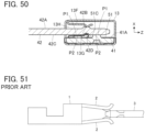
- JP 2015-222621 A discloses a connector as illustrated in FIG. 51 .
- a second terminal 3 is inserted between a pair of elastic contact pieces 2 of a first terminal 1, whereby the pair of elastic contact pieces 2 each make contact with the second terminal 3 with a predetermined elastic force, and hence the first terminal 1 and the second terminal 3 are electrically connected to each other.
- the second terminal 3 is slid while constantly receiving a predetermined elastic force from the pair of elastic contact pieces 2; therefore, slid portions of the elastic contact pieces 2 and the second terminal 3 are easily worn.
- the present invention has been made to overcome the conventional problems as above and aims at providing a connector that can electrically connect a first terminal to a second terminal with high reliability even with an operation of insertion and withdrawal of the second terminal into and from the first terminal.
- the connector according to the invention is a connector in which a second terminal of flat plate shape is moved in parallel with and superposed on a first terminal of flat plate shape to thereby connect the first terminal and the second terminal to each other, the connector including:
- FIG. 1 shows a connector according to Embodiment 1.
- the connector includes a first terminal 11 and a second terminal 12.
- a spring member retaining portion 13 is attached, and the first terminal 11 and the spring member retaining portion 13 constitute a first terminal structure S1.
- the first terminal 11 and the second terminal 12 are each made of a conductive material such as metal and have a flat plate shape.
- the second terminal 12 is inserted in the first terminal structure S1 to be thereby electrically connected to the first terminal 11.
- first terminal 11 and the second terminal 12 both of flat plate shape are defined as extending along a YZ plane, while the direction in which the second terminal 12 is inserted into the first terminal structure S1 is defined as a +Z direction, and the direction perpendicular to the first terminal 11 and the second terminal 12 as a X direction.
- FIG. 2 shows the first terminal structure S1.
- the spring member retaining portion 13 is illustrated by dashed lines to show an interior of the spring member retaining portion 13.
- the spring member retaining portion 13 is constituted of a plate member such as a metal plate being bent, and has a substantially polygonal tube shape whose central axis extends along the Y direction.
- the spring member retaining portion 13 includes a bottom plate portion 13A situated on the -X direction side and extending along a YZ plane, a top plate portion 13B situated on the +X direction side and extending along a YZ plane, a front plate portion 13C situated on the -Z direction side and extending along an XY plane, and a rear plate portion 13D situated on the +Z direction side and extending along an XY plane.
- the front plate portion 13C is provided with an opening 13E into which the second terminal 12 is to be inserted.
- a spring member 13F extending while being bent in the -X direction and the +Z direction is formed at the -Z directional end of the top plate portion 13B.
- a pressing portion 13G is formed to extend in the Y direction and protrude toward the -X direction.
- the height of the top plate portion 13B in the X direction from the bottom plate portion 13A has a larger dimension than the thickness of the first terminal 11 in the X direction, and the spring member retaining portion 13 is attached to the first terminal 11 in such a manner that the first terminal 11 is situated inside the spring member retaining portion 13 and in contact with the bottom plate portion 13A of the spring member retaining portion 13.
- the +X directional surface of the first terminal 11 constitutes a first opposing surface 11A opposing the second terminal 12, and between the first opposing surface 11A of the first terminal 11 and the spring member 13F, formed is a second terminal accommodation portion 13H in which the second terminal 12 is inserted.
- the first opposing surface 11A of the first terminal 11 is provided with three first protrusion portions 11B each projecting toward the +X direction.
- the three first protrusion portions 11B are arranged at three vertexes of an isosceles triangle T1 having a symmetrical shape with respect to the Z direction, and a first contact portion P1 is formed at a top part, facing in the +X direction, of each first protrusion portion 11B.
- the first opposing surface 11A of the first terminal 11 is also provided with two projections 11C each projecting in the +X direction.
- the two projections 11C are separately arranged on two sides of the isosceles triangle T1, the two sides having the same length. Specifically, each projection 11C is situated at a center part of the relevant side of the isosceles triangle T1 and is so situated as not to overlap the three first contact portions P1 in the Z direction, i.e., insertion direction of the second terminal 12.
- the projection height of the two projections 11C from the first opposing surface 11A is higher than the projection height of the three first protrusion portions 11B from the first opposing surface 11A, and a top part in the +X direction of each projection 11C is situated on the +X direction side from the first contact portion P1.
- the three first protrusion portions 11B and the two projections 11C can be formed by subjecting the first terminal 11 to press working, and the back surface on the -X direction side of the first terminal 11 is thus provided with five recesses corresponding to the first protrusion portions 11B and the projections 11C as shown in FIG. 5 . That is, the two projections 11C are integrally formed with the first opposing surface 11A.
- the front surface on the +X direction side of the second terminal 12 constitutes a spring member-opposing surface 12A opposing the spring member 13F when the second terminal 12 is inserted in the second terminal accommodation portion 13H of the first terminal structure S1, and the spring member-opposing surface 12A is provided with a pressed portion 12B projecting toward the +X direction.
- the pressed portion 12B has a shape elongated along the Y direction.
- the back surface on the -X direction side of the second terminal 12 constitutes a second opposing surface 12C opposing the first opposing surface 11A of the first terminal 11 when the second terminal 12 is inserted in the second terminal accommodation portion 13H of the first terminal structure S1, and the second opposing surface 12C is provided with a projection accommodation portion 12D of recess shape recessed toward the +X direction.
- the projection accommodation portion 12D is elongated along the Y direction and has a size with which the two projections 11C of the first terminal 11 can be together accommodated therein. Further, the projection accommodation portion 12D has a depth dimension larger than the height difference in the X direction between the top parts of the projections 11C and the first contact portion P1 of the first terminal 11.
- the pressed portion 12B and the projection accommodation portion 12D can be simultaneously formed by a single step of subjecting the second terminal 12 to press working, and are arranged at the same position in a YZ plane.
- the second terminal 12 shown in FIG. 1 is moved in the +Z direction from the -Z direction, and the tip end of the second terminal 12 is inserted into the spring member retaining portion 13 through the opening 13E of the spring member retaining portion 13 of the first terminal structure S1 as shown in FIG. 8 .
- the +Z directional tip end of the second terminal 12 is inserted in the +Z direction as passing between the first terminal 11 and the spring member 13F, and the top parts of the two projections 11C of the first terminal 11 are situated on the +X direction side from the first contact portions P1.
- the second opposing surface 12C, facing in the -X direction, of the second terminal 12 is situated over the top parts of the two projections 11C without making contact with the first contact portions P1
- the spring member-opposing surface 12A, facing in the +X direction, of the second terminal 12 makes contact with the pressing portion 13G of the spring member 13F to elastically compress the spring member 13F toward the +X direction.
- the second terminal 12 is inserted in the second terminal accommodation portion 13H formed between the spring member 13F and the first opposing surface 11A of the first terminal 11.
- the pressed portion 12B projecting in the +X direction from the spring member-opposing surface 12A of the second terminal 12 is situated on the -Z direction side from the pressing portion 13G of the spring member 13F and is thus not in contact with the pressing portion 13G yet.
- the pressed portion 12B of the second terminal 12 makes contact with the pressing portion 13G of the spring member 13F, and the pressing portion 13G rides on the pressed portion 12B projecting in the +X direction from the spring member-opposing surface 12A of the second terminal 12.
- connection completion position when insertion of the second terminal 12 in the +Z direction continues, as shown in FIG. 11 , with the pressing portion 13G of the spring member 13F being kept on the pressed portion 12B of the second terminal 12, the projection accommodation portion 12D formed in the second opposing surface 12C of the second terminal 12 is situated on the +X direction side from the two projections 11C of the first terminal 11 and accommodates the two projections 11C.
- the position of the second terminal 12 in the second terminal accommodation portion 13H at this time is called "connection completion position.”
- the projection accommodation portion 12D of the second terminal 12 has a depth dimension larger than the height difference in the X direction between the top parts of the projections 11C and the first contact portions P1 of the first terminal 11, when the second terminal 12 is disposed at the connection completion position and the two projections 11C are thus accommodated in the projection accommodation portion 12D, a predetermined gap is formed between the top part of each projection 11C and the bottom part of the projection accommodation portion 12D, and the second opposing surface 12C of the second terminal 12 makes contact with the three first contact portions P1 of the first terminal 11.
- the second terminal 12 Since the pressing portion 13G of the spring member 13F is positioned on the pressed portion 12B of the second terminal 12 as shown in FIG. 11 , the second terminal 12 is pressed against the first terminal 11 by the spring member 13F via the pressed portion 12B, and the first contact portions P1 and the second contact portions P2 make contact with each other with a predetermined contact pressure, whereby the first terminal 11 and the second terminal 12 are electrically connected to each other.
- the second opposing surface 12C of the second terminal 12 is in contact only with the top parts of the two projections 11C of the first terminal 11, and when the second terminal 12 is disposed at the connection completion position and the two projections 11C are accommodated in the projection accommodation portion 12D, the second opposing surface 12C of the second terminal 12 makes contact with the three first contact portions P1 of the first terminal 11 for the first time.
- the two projections 11C of the first terminal 11 are so situated as not to overlap the three first contact portions P1 in the Z direction, i.e., insertion direction of the second terminal 12, the three first contact portions P1 of the first terminal 11 make contact with the three second contact portions P2 of the second terminal 12 without being rubbed by any part of the second terminal 12. Similarly, the three second contact portions P2 of the second terminal 12 make contact with the three first contact portions P1 of the first terminal 11 without being rubbed by any part of the first terminal 11.
- FIG. 12 shows a connector according to Embodiment 2.
- the connector includes a first terminal 21 and a second terminal 22.
- the spring member retaining portion 13 is attached, and the first terminal 21 and the spring member retaining portion 13 constitute a first terminal structure S2.
- the first terminal 21 and the second terminal 22 are each made of a conductive material such as metal and have a flat plate shape.
- the second terminal 22 is inserted in the first terminal structure S2 to be thereby electrically connected to the first terminal 21.
- the spring member retaining portion 13 is the same as the spring member retaining portion 13 used in the first terminal structure S1 in Embodiment 1.
- the spring member retaining portion 13 is attached to the first terminal 21 in such a manner that the first terminal 21 is situated inside the spring member retaining portion 13 and in contact with the bottom plate portion 13A of the spring member retaining portion 13.
- the +X directional surface of the first terminal 21 constitutes a first opposing surface 21A opposing the second terminal 22, and between the first opposing surface 21A of the first terminal 21 and the spring member 13F, formed is the second terminal accommodation portion 13H in which the second terminal 22 is inserted.
- the first opposing surface 21A of the first terminal 21 is provided with two projections 21C each projecting in the +X direction.
- the two projections 21C are aligned in the Y direction.
- the two projections 21C can be formed by subjecting the first terminal 21 to press working, and the back surface on the -X direction side of the first terminal 21 is thus provided with two recesses corresponding to the two projections 21C as shown in FIG. 15 . That is, the two projections 21C are formed as a result of deformation of the first opposing surface 21A through press working.
- the front surface on the +X direction side of the second terminal 22 constitutes a spring member-opposing surface 22A opposing the spring member 13F when the second terminal 22 is inserted in the second terminal accommodation portion 13H of the first terminal structure S2, and the spring member-opposing surface 22A is provided with a pressed portion 22B projecting toward the +X direction.
- the pressed portion 22B has a shape elongated along the Y direction.
- the back surface on the -X direction side of the second terminal 22 constitutes a second opposing surface 22C opposing the first opposing surface 21A of the first terminal 21 when the second terminal 22 is inserted in the second terminal accommodation portion 13H of the first terminal structure S2, and the second opposing surface 22C is provided with a projection accommodation portion 22D of recess shape recessed toward the +X direction.
- the projection accommodation portion 22D is elongated along the Y direction and has a size with which the two projections 21C of the first terminal 21 can be together accommodated therein.
- the pressed portion 22B and the projection accommodation portion 22D can be simultaneously formed by a single step of subjecting the second terminal 22 to press working, and are arranged at the same position in a YZ plane.
- the second opposing surface 22C of the second terminal 22 is provided with three second protrusion portions 22E each projecting toward the -X direction.
- the three second protrusion portions 22E are arranged at three vertexes of an isosceles triangle T2 having a symmetrical shape with respect to the Z direction, and a second contact portion P2 is formed at a top part, facing in the -X direction, of each second protrusion portion 22E.
- the two projections 21C of the first terminal 21 are accommodated in the projection accommodation portion 22D, while the three second contact portions P2 are so situated as not to overlap the two projections 21C in the Z direction, i.e., insertion direction of the second terminal 22.
- the projection height of the two projections 21C of the first terminal 21 from the first opposing surface 21A is set higher than the height of the three second contact portions P2 from the second opposing surface 22C in the second terminal 22.
- the projection accommodation portion 22D of the second terminal 22 has a depth dimension larger than the difference between the projection height of the projections 21C of the first terminal 21 from the first opposing surface 21A and the height of the second contact portions P2 of the second terminal 22 from the second opposing surface 22C.
- the second terminal 22 shown in FIG. 12 is moved in the +Z direction from the -Z direction, and the tip end of the second terminal 22 is inserted into the spring member retaining portion 13 through the opening 13E of the spring member retaining portion 13 of the first terminal structure S2 as shown in FIG. 18 .
- the second contact portion P2 of the second terminal 22 does not make contact with the first opposing surface 21A of the first terminal 21, and the second opposing surface 22C of the second terminal 22 is situated over the top part of the projection 21C of the first terminal 21.
- the spring member-opposing surface 22A, facing in the +X direction, of the second terminal 22 makes contact with the pressing portion 13G of the spring member 13F to elastically compress the spring member 13F toward the +X direction.
- the second terminal 22 is inserted in the second terminal accommodation portion 13H formed between the spring member 13F and the first opposing surface 21A of the first terminal 21.
- the pressed portion 22B of the second terminal 22 is situated on the -Z direction side from the pressing portion 13G of the spring member 13F and is thus not in contact with the pressing portion 13G yet.
- the pressed portion 22B of the second terminal 22 makes contact with the pressing portion 13G of the spring member 13F, and the pressing portion 13G rides on the pressed portion 22B projecting in the +X direction from the spring member-opposing surface 22A of the second terminal 22.
- connection completion position when insertion of the second terminal 22 in the +Z direction continues, as shown in FIG. 21 , with the pressing portion 13G of the spring member 13F being kept on the pressed portion 22B of the second terminal 22, the projection accommodation portion 22D formed in the second opposing surface 22C of the second terminal 22 is situated on the +X direction side from the two projections 21C of the first terminal 21 and accommodates the two projections 21C.
- the position of the second terminal 22 in the second terminal accommodation portion 13H at this time is called "connection completion position.”
- the projection accommodation portion 22D of the second terminal 22 has a depth dimension larger than the difference between the projection height of the projections 21C of the first terminal 21 from the first opposing surface 21A and the height of the second contact portions P2 of the second terminal 22 from the second opposing surface 22C, when the second terminal 22 is disposed at the connection completion position and the two projections 21C are thus accommodated in the projection accommodation portion 22D, a predetermined gap is formed between the top part of each projection 21C and the bottom part of the projection accommodation portion 22D, and the three second contact portions P2 of the second terminal 22 make contact with the first opposing surface 21A of the first terminal 21.
- the second terminal 22 Since the pressing portion 13G of the spring member 13F is positioned on the pressed portion 22B of the second terminal 22 as shown in FIG. 21 , the second terminal 22 is pressed against the first terminal 21 by the spring member 13F via the pressed portion 22B, and the first contact portions P1 and the second contact portions P2 make contact with each other with a predetermined contact pressure, whereby the first terminal 21 and the second terminal 22 are electrically connected to each other.
- the first opposing surface 21A of the first terminal 21 is not in contact with any part of the second terminal 22, and when the second terminal 22 is disposed at the connection completion position and the two projections 21C are accommodated in the projection accommodation portion 22D, the three second contact portions P2 of the second terminal 22 make contact with the first opposing surface 21A of the first terminal 21 for the first time.
- the two projections 21C of the first terminal 21 are so situated as not to overlap the three second contact portions P2 of the second terminal 22 in the Z direction, i.e., insertion direction of the second terminal 22, the three second contact portions P2 of the second terminal 22 make contact with the three first contact portions P1 of the first terminal 21 without being rubbed by any part of the first terminal 21.
- the three first contact portions P1 of the first terminal 21 make contact with the three second contact portions P2 of the second terminal 22 without being rubbed by any part of the second terminal 22.
- FIG. 22 shows a connector according to Embodiment 3.
- the connector includes a first terminal 31 and a second terminal 32.
- the spring member retaining portion 13 is attached, and the first terminal 31 and the spring member retaining portion 13 constitute a first terminal structure S3.
- the first terminal 31 and the second terminal 32 are each made of a conductive material such as metal and have a flat plate shape.
- the second terminal 32 is inserted in the first terminal structure S3 to be thereby electrically connected to the first terminal 31.
- the spring member retaining portion 13 is the same as the spring member retaining portion 13 used in the first terminal structure S1 in Embodiment 1.
- the spring member retaining portion 13 is attached to the first terminal 31 in such a manner that the first terminal 31 is situated inside the spring member retaining portion 13 and in contact with the bottom plate portion 13A of the spring member retaining portion 13.
- the +X directional surface of the first terminal 31 constitutes a first opposing surface 31A opposing the second terminal 32, and between the first opposing surface 31A of the first terminal 31 and the spring member 13F, formed is the second terminal accommodation portion 13H in which the second terminal 32 is inserted.
- the first opposing surface 31A of the first terminal 31 is provided with three first protrusion portions 31B each projecting toward the +X direction.
- the three first protrusion portions 31B are arranged at three vertexes of an isosceles triangle T3 having a symmetrical shape with respect to the Z direction, and a first contact portion P1 is formed at a top part, facing in the +X direction, of each first protrusion portion 31B.
- the first opposing surface 31A of the first terminal 31 is also provided with two projections 31C each projecting in the +X direction.
- the two projections 31C are arranged outside the isosceles triangle T3.
- the projections 31C are separately situated on the +Y direction side and the -Y direction side from the isosceles triangle T3 with a distance therebetween in the Y direction, and are so situated as not to overlap the three first contact portions P1 in the Z direction, i.e., insertion direction of the second terminal 32.
- the projection height of the two projections 31C from the first opposing surface 31A is higher than the projection height of the three first protrusion portions 31B from the first opposing surface 31A, and a top part in the +X direction of each projection 31C is situated on the +X direction side from the first contact portion P1.
- the three first protrusion portions 31B and the two projections 31C can be formed by subjecting the first terminal 31 to press working, and the back surface on the -X direction side of the first terminal 31 is thus provided with five recesses corresponding to the first protrusion portions 31B and the projections 31C as shown in FIG. 25 .
- the front surface on the +X direction side of the second terminal 32 constitutes a spring member-opposing surface 32A opposing the spring member 13F when the second terminal 32 is inserted in the second terminal accommodation portion 13H of the first terminal structure S3, and the spring member-opposing surface 32A is provided with two pressed portions 32B projecting toward the +X direction.
- the two pressed portions 32B are aligned in the Y direction and disposed with a distance therebetween in the Y direction.
- the back surface on the -X direction side of the second terminal 32 constitutes a second opposing surface 32C opposing the first opposing surface 31A of the first terminal 31 when the second terminal 32 is inserted in the second terminal accommodation portion 13H of the first terminal structure S3, and the second opposing surface 32C is provided with two projection accommodation portions 32D of recess shape recessed toward the +X direction.
- the two projection accommodation portions 32D are aligned in the Y direction and disposed with a distance therebetween in the Y direction.
- the distance in the Y direction between the two projection accommodation portions 32D is set equal to the distance in the Y direction between the two projections 31C of the first terminal 31.
- each projection accommodation portion 32D has a size with which the projection 31C of the first terminal 31 can be accommodated therein.
- the two projection accommodation portions 32D each have a depth dimension larger than the height difference in the X direction between the top part of the projection 31C and the first contact portion P1 of the first terminal 31.
- the two pressed portions 32B and the two projection accommodation portions 32D can be simultaneously formed by a single step of subjecting the second terminal 32 to press working, and are arranged at the same positions in a YZ plane.
- the second terminal 32 shown in FIG. 22 is moved in the +Z direction from the -Z direction, and the tip end of the second terminal 32 is inserted into the spring member retaining portion 13 through the opening 13E of the spring member retaining portion 13 of the first terminal structure S3 as shown in FIG. 28 .
- the +Z directional tip end of the second terminal 32 is inserted in the +Z direction as passing between the first terminal 31 and the spring member 13F, and the top parts of the two projections 31C of the first terminal 31 are situated on the +X direction side from the first contact portions P1.
- the second opposing surface 32C, facing in the -X direction, of the second terminal 32 is situated over the top parts of the two projections 31C without making contact with the first contact portions P1
- the spring member-opposing surface 32A, facing in the +X direction, of the second terminal 32 makes contact with the pressing portion 13G of the spring member 13F to elastically compress the spring member 13F toward the +X direction.
- the second terminal 32 is inserted in the second terminal accommodation portion 13H formed between the spring member 13F and the first opposing surface 31A of the first terminal 31.
- the pressed portions 32B projecting in the +X direction from the spring member-opposing surface 32A of the second terminal 32 are situated on the -Z direction side from the pressing portion 13G of the spring member 13F and are thus not in contact with the pressing portion 13G yet.
- connection completion position when insertion of the second terminal 32 in the +Z direction continues, as shown in FIGS. 33 and 34 , with the pressing portion 13G of the spring member 13F being kept on the pressed portions 32B of the second terminal 32, the projection accommodation portions 32D formed in the second opposing surface 32C of the second terminal 32 are situated on the +X direction side from the two projections 31C of the first terminal 31 and separately accommodate the two projections 31C.
- the position of the second terminal 32 in the second terminal accommodation portion 13H at this time is called "connection completion position.”
- the projection accommodation portions 32D of the second terminal 32 have a depth dimension larger than the height difference in the X direction between the top parts of the projections 31C and the first contact portions P1 of the first terminal 31, when the second terminal 32 is disposed at the connection completion position and the two projections 31C are thus accommodated in the projection accommodation portions 32D, a predetermined gap is formed between the top part of each projection 31C and the bottom part of each projection accommodation portion 32D, and the second opposing surface 32C of the second terminal 32 makes contact with the three first contact portions P1 of the first terminal 31.
- the second terminal 32 Since the pressing portion 13G of the spring member 13F is positioned on the pressed portions 32B of the second terminal 32 as shown in FIGS. 33 and 34 , the second terminal 32 is pressed against the first terminal 31 by the spring member 13F via the pressed portions 32B, and the first contact portions P1 and the second contact portions P2 make contact with each other with a predetermined contact pressure, whereby the first terminal 31 and the second terminal 32 are electrically connected to each other.
- the second opposing surface 32C of the second terminal 32 is in contact only with the top parts of the two projections 31C of the first terminal 31, and when the second terminal 32 is disposed at the connection completion position and the two projections 31C are accommodated in the projection accommodation portions 32D, the second opposing surface 32C of the second terminal 32 makes contact with the three first contact portions P1 of the first terminal 31 for the first time.
- the two projections 31C of the first terminal 31 are so situated as not to overlap the three first contact portions P1 in the Z direction, i.e., insertion direction of the second terminal 32, the three first contact portions P1 of the first terminal 31 make contact with the three second contact portions P2 of the second terminal 32 without being rubbed by any part of the second terminal 32. Similarly, the three second contact portions P2 of the second terminal 32 make contact with the three first contact portions P1 of the first terminal 31 without being rubbed by any part of the first terminal 31.
- FIG. 35 shows a connector according to Embodiment 4.
- the connector includes a first terminal 41 and a second terminal 42.
- a projection forming component 51 and the spring member retaining portion 13 are attached, and the first terminal 41, the projection forming component 51, and the spring member retaining portion 13 constitute a first terminal structure S4.
- the first terminal 41 and the second terminal 42 are each made of a conductive material such as metal and have a flat plate shape.
- the second terminal 42 is inserted in the first terminal structure S4 to be thereby electrically connected to the first terminal 41.
- the spring member retaining portion 13 is the same as the spring member retaining portion 13 used in the first terminal structure S1 in Embodiment 1.
- the spring member retaining portion 13 is attached to the first terminal 41 in such a manner that the first terminal 41 is situated inside the spring member retaining portion 13 and in contact with the bottom plate portion 13A of the spring member retaining portion 13.
- the +X directional surface of the first terminal 41 constitutes a first opposing surface 41A opposing the second terminal 42, the projection forming component 51 is attached on the first opposing surface 41A in such a manner that part of the first opposing surface 41A is exposed, and between the exposed part of the first opposing surface 41Atogether with the projection forming component 51 and the spring member 13F, formed is the second terminal accommodation portion 13H in which the second terminal 42 is inserted.
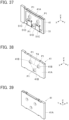
- FIG. 37 shows the first terminal 41 to which the projection forming component 51 is attached.
- the projection forming component 51 has a frame shape, and part of the first opposing surface 41A of the first terminal 41 is exposed through an inner part of the projection forming component 51.
- the first opposing surface 41A of the first terminal 41 is provided with three first protrusion portions 41B each projecting toward the +X direction.
- the three first protrusion portions 41B are arranged at three vertexes of an isosceles triangle T4 having a symmetrical shape with respect to the Z direction, and a first contact portion P1 is formed at a top part, facing in the +X direction, of each first protrusion portion 41B.
- the three first protrusion portions 41B can be formed by subjecting the first terminal 41 to press working, and the back surface on the -X direction side of the first terminal 41 is thus provided with three recesses corresponding to the first protrusion portions 41B as shown in FIG. 39 .
- the projection forming component 51 is formed of a metal plate cut out in a frame shape and bent as shown in FIG. 40 , and includes a frame shape portion 51A extending along a YZ plane and two tubular portions 51B joined to the frame shape portion 51A.
- the two tubular portions 51B are each formed by bending the metal plate constituting the projection forming component 51 into a tubular shape about a center axis extending in the Y direction, are aligned in the Y direction, and are disposed with a distance therebetween in the Y direction.
- the two tubular portions 51B form two projections 51C each projecting in the +X direction.
- a cutout 51D is formed by cutting out a +X directional part of the tubular portion 51B.
- each tubular portion 51B being disposed with a distance therebetween in the Y direction, and each tubular portion 51B being provided with the cutout 51D, it is configured such that, as shown in FIG. 37 , the projections 51C are so situated as not to overlap the three first contact portions P1 of the first terminal 41 in the Z direction, i.e., insertion direction of the second terminal 42 when the projection forming component 51 is attached to the first opposing surface 41A of the first terminal 41.
- the projection height, from the first opposing surface 41A, of the projections 51C formed of the projection forming component 51 is higher than the height of the three first contact portions P1 from the first opposing surface 31A, and a top part in the +X direction of each projection 51C is situated on the +X direction side from the first contact portion P1.
- the projection forming component 51 as above can be attached to the first opposing surface 41A of the first terminal 41 by, for example, welding.
- the front surface on the +X direction side of the second terminal 42 constitutes a spring member-opposing surface 42A opposing the spring member 13F when the second terminal 42 is inserted in the second terminal accommodation portion 13H of the first terminal structure S4, and the spring member-opposing surface 42A is provided with two pressed portions 42B projecting toward the +X direction.
- the two pressed portions 42B are aligned in the Y direction and disposed with a distance therebetween in the Y direction.
- the back surface on the -X direction side of the second terminal 42 constitutes a second opposing surface 42C opposing the first opposing surface 41A of the first terminal 41 when the second terminal 42 is inserted in the second terminal accommodation portion 13H of the first terminal structure S4, and the second opposing surface 42C is provided with two projection accommodation portions 42D of recess shape recessed toward the +X direction.
- the two projection accommodation portions 42D are aligned in the Y direction and disposed with a distance therebetween in the Y direction.
- the two projection accommodation portions 42D each have a size and have a Y directional distance therebetween with which the two projections 51C of the projection forming component 51 attached to the first terminal 41 can be separately accommodated therein.
- the two projection accommodation portions 42D each have a depth dimension larger than the height difference in the X direction between the +X directional top part of each projection 51C of the projection forming component 51 and the first contact portion P1 of the first terminal 41.
- the two pressed portions 42B of the second terminal 42 and the two projection accommodation portions 42D can be simultaneously formed by a single step of subjecting the second terminal 42 to press working, and are arranged at the same positions in a YZ plane.
- the second terminal 42 shown in FIG. 35 is moved in the +Z direction from the -Z direction, and the tip end of the second terminal 42 is inserted into the spring member retaining portion 13 through the opening 13E of the spring member retaining portion 13 of the first terminal structure S4 as shown in FIG. 44 .
- the +Z directional tip end of the second terminal 42 is inserted in the +Z direction as passing between the projection forming component 51 and the spring member 13F, and the +X directional top parts of the two projections 51C of the projection forming component 51 are situated on the +X direction side from the first contact portions P1.
- the second opposing surface 42C, facing in the -X direction, of the second terminal 42 is situated over the top parts of the two projections 51C without making contact with the first contact portions P1
- the spring member-opposing surface 42A, facing in the +X direction, of the second terminal 42 makes contact with the pressing portion 13G of the spring member 13F to elastically compress the spring member 13F toward the +X direction.
- the second terminal 42 is inserted in the second terminal accommodation portion 13H formed between the spring member 13F and the first opposing surface 41A of the first terminal 41 together with the projection forming component 51.
- the pressed portions 42B projecting in the +X direction from the spring member-opposing surface 42A of the second terminal 42 are situated on the -Z direction side from the pressing portion 13G of the spring member 13F and are thus not in contact with the pressing portion 13G yet.
- connection completion position when insertion of the second terminal 42 in the +Z direction continues, as shown in FIGS. 49 and 50 , with the pressing portion 13G of the spring member 13F being kept on the pressed portions 42B of the second terminal 42, the projection accommodation portions 42D formed in the second opposing surface 42C of the second terminal 42 are situated on the +X direction side from the two projections 51C of the projection forming component 51 and separately accommodate the two projections 51C.
- the position of the second terminal 42 in the second terminal accommodation portion 13H at this time is called "connection completion position."
- the projection accommodation portions 42D of the second terminal 42 have a depth dimension larger than the height difference in the X direction between the +X directional top parts of the projections 51C of the projection forming component 51 and the first contact portions P1 of the first terminal 41, when the second terminal 42 is disposed at the connection completion position and the two projections 51C are thus accommodated in the projection accommodation portions 42D, a predetermined gap is formed between the top part of each projection 51C and the bottom part of each projection accommodation portion 42D, and the second opposing surface 42C of the second terminal 42 makes contact with the three first contact portions P1 of the first terminal 41.
- the second terminal 42 Since the pressing portion 13G of the spring member 13F is positioned on the pressed portions 42B of the second terminal 42 as shown in FIGS. 49 and 50 , the second terminal 42 is pressed against the first terminal 41 by the spring member 13F via the pressed portions 42B, and the first contact portions P1 and the second contact portions P2 make contact with each other with a predetermined contact pressure, whereby the first terminal 41 and the second terminal 42 are electrically connected to each other.
- the second opposing surface 42C of the second terminal 42 is in contact only with the top parts of the two projections 51C of the projection forming component 51, and when the second terminal 42 is disposed at the connection completion position and the two projections 51C are separately accommodated in the projection accommodation portions 42D, the second opposing surface 42C of the second terminal 42 makes contact with the three first contact portions P1 of the first terminal 41 for the first time.
- the two projections 51C of the projection forming component 51 are so situated as not to overlap the three first contact portions P1 in the Z direction, i.e., insertion direction of the second terminal 42, the three first contact portions P1 of the first terminal 41 make contact with the three second contact portions P2 of the second terminal 42 without being rubbed by any part of the second terminal 42.
- the three second contact portions P2 of the second terminal 42 make contact with the three first contact portions P1 of the first terminal 41 without being rubbed by any part of the first terminal 41 and the projection forming component 51.
- the three first contact portions P1 of the first terminal 11, 31, 41 are each formed of, for example, the top part of the first protrusion portion 11B, 31B, 41B of the first terminal 11, 31, 41, but the invention is not limited thereto.
- three metal balls are rotatably retained by the first terminal 11, 31, 41 in such a manner that part of each metal ball projects from the first opposing surface 11A, 31A, 41A, and the metal ball surface projecting from the first opposing surface 11A, 31A, 41A is used as the first contact portion P1, whereby the first terminal 11, 31, 41 can be electrically connected to the second terminal 12, 32, 42.
- the connector is preferably configured such that the three first contact portions P1 make contact with the three second contact portions P2 as in Embodiments 1 to 4, because the first terminal 11, 21, 31, 41 and the second terminal 12, 22, 32, 42 when connected to each other are positionally stabilized, thereby improving reliability of the electrical connection.
- three first contact portions P1 and three second contact portions P2 are arranged at three vertexes of the isosceles triangle T1 to T4, but the contact portions are not limited to be arranged at vertexes of an isosceles triangle. Meanwhile, the three first contact portions P1 and the three second contact portions P2 are preferably arranged at three vertexes of the isosceles triangle T1 to T4 for positionally stabilizing the first terminal 11, 21, 31, 41 and the second terminal 12, 22, 32, 42 when connected to each other.
- the two projections 11C, 21C, 31C, 51C are used, but the invention is not limited thereto.
- the two projections 11C, 21C, 31C, 51C aligned in the Y direction are preferably used as in Embodiments 1 to 4 for positionally stabilizing the second terminal 12, 22, 32, 42 in the process of insertion.
Landscapes
- Coupling Device And Connection With Printed Circuit (AREA)
Abstract
Description
- The present invention relates to a connector, particularly to a connector in which a second terminal of flat plate shape is moved in parallel with and superposed on a first terminal of flat plate shape, thereby connecting the first terminal and the second terminal to each other.
- Conventionally, there has been known a connector for connecting a first terminal and a second terminal to each other with an operation of insertion and withdrawal of the second terminal into and from the first terminal.
- For example,
JP 2015-222621 A FIG. 51 . In this connector, asecond terminal 3 is inserted between a pair ofelastic contact pieces 2 of afirst terminal 1, whereby the pair ofelastic contact pieces 2 each make contact with thesecond terminal 3 with a predetermined elastic force, and hence thefirst terminal 1 and thesecond terminal 3 are electrically connected to each other. - Meanwhile, in the course of inserting the
second terminal 3 between the pair ofelastic contact pieces 2 of thefirst terminal 1, thesecond terminal 3 is slid while constantly receiving a predetermined elastic force from the pair ofelastic contact pieces 2; therefore, slid portions of theelastic contact pieces 2 and thesecond terminal 3 are easily worn. - In addition, in the connecting state between the
first terminal 1 and thesecond terminal 3, also when thefirst terminal 1 and thesecond terminal 3 are moved relatively to each other by, for example, receiving any external force, slid portions between theelastic contact pieces 2 and thesecond terminal 3 are easily worn. - Hence, reliability of electrical connection between the
first terminal 1 and thesecond terminal 3 may be impaired. - The present invention has been made to overcome the conventional problems as above and aims at providing a connector that can electrically connect a first terminal to a second terminal with high reliability even with an operation of insertion and withdrawal of the second terminal into and from the first terminal.
- The connector according to the invention is a connector in which a second terminal of flat plate shape is moved in parallel with and superposed on a first terminal of flat plate shape to thereby connect the first terminal and the second terminal to each other, the connector including:
- a spring member attached to the first terminal and configured to press the second terminal toward the first terminal;
- wherein the first terminal includes a first opposing surface and a first contact portion facing the second terminal,
- a second terminal accommodation portion in which the second terminal is inserted is formed between the first opposing surface and the spring member,
- the second terminal includes a second opposing surface opposing the first opposing surface, a second contact portion facing the first terminal, and a pressed portion formed on and projecting from a spring member-opposing surface opposing the spring member,
- one of the first opposing surface and the second opposing surface is provided with a projection projecting toward another of the first opposing surface and the second opposing surface, and the another is provided with a projection accommodation portion of recess shape for accommodating the projection, and
- when the second terminal is inserted along a predetermined insertion direction to a predetermined connection completion position in the second terminal accommodation portion, the projection is accommodated in the projection accommodation portion so that the second terminal is retained at the predetermined connection completion position, the second terminal is pressed against the first terminal by the spring member via the pressed portion, and the first contact portion and the second contact portion make contact with each other, whereby the first terminal and the second terminal are electrically connected to each other.
-
-
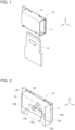
FIG. 1 is a perspective view showing a connector according toEmbodiment 1 before connection. -
FIG. 2 is a perspective view showing a first terminal structure inEmbodiment 1. -
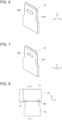
FIG. 3 is a side view showing the first terminal structure inEmbodiment 1. -
FIG. 4 is a perspective view of the first terminal inEmbodiment 1 when viewed from a front surface side. -
FIG. 5 is a perspective view of the first terminal inEmbodiment 1 when viewed from a back surface side. -
FIG. 6 is a perspective view of a second terminal inEmbodiment 1 when viewed from a front surface side. -
FIG. 7 is a perspective view of the second terminal inEmbodiment 1 when viewed from a back surface side. -
FIG. 8 is a plan view showing the connector ofEmbodiment 1 at an early stage of insertion of the second terminal. -
FIG. 9 is a cross-sectional view corresponding to line A-A ofFIG. 8 and showing the connector ofEmbodiment 1 at an early stage of insertion of the second terminal. -
FIG. 10 is a cross-sectional view corresponding to line A-A ofFIG. 8 and showing the connector ofEmbodiment 1 in the process of insertion of the second terminal. -
FIG. 11 is a cross-sectional view corresponding to line A-A ofFIG. 8 and showing the connector ofEmbodiment 1 with the second terminal being inserted to a connection completion position. -
FIG. 12 is a perspective view showing a connector according toEmbodiment 2 before connection. -
FIG. 13 is a side view showing a first terminal structure inEmbodiment 2. -
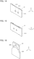
FIG. 14 is a perspective view of the first terminal inEmbodiment 2 when viewed from a front surface side. -
FIG. 15 is a perspective view of the first terminal inEmbodiment 2 when viewed from a back surface side. -
FIG. 16 is a perspective view of a second terminal inEmbodiment 2 when viewed from a front surface side. -
FIG. 17 is a perspective view of the second terminal inEmbodiment 2 when viewed from a back surface side. -
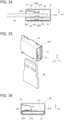
FIG. 18 is a plan view showing the connector ofEmbodiment 2 at an early stage of insertion of the second terminal. -
FIG. 19 is a cross-sectional view corresponding to line B-B ofFIG. 18 and showing the connector ofEmbodiment 2 at an early stage of insertion of the second terminal. -
FIG. 20 is a cross-sectional view corresponding to line B-B ofFIG. 18 and showing the connector ofEmbodiment 2 in the process of insertion of the second terminal. -
FIG. 21 is a cross-sectional view corresponding to line B-B ofFIG. 18 and showing the connector ofEmbodiment 2 with the second terminal being inserted to a connection completion position. -
FIG. 22 is a perspective view showing a connector according toEmbodiment 3 before connection. -
FIG. 23 is a side view showing a first terminal structure in Embodiment 3. -
FIG. 24 is a perspective view of the first terminal inEmbodiment 3 when viewed from a front surface side. -
FIG. 25 is a perspective view of the first terminal inEmbodiment 3 when viewed from a back surface side. -
FIG. 26 is a perspective view of a second terminal inEmbodiment 3 when viewed from a front surface side. -
FIG. 27 is a perspective view of the second terminal inEmbodiment 3 when viewed from a back surface side. -
FIG. 28 is a plan view showing the connector ofEmbodiment 3 at an early stage of insertion of the second terminal. -
FIG. 29 is a cross-sectional view corresponding to line C-C ofFIG. 28 and showing the connector ofEmbodiment 3 at an early stage of insertion of the second terminal. -
FIG. 30 is a cross-sectional view corresponding to line D-D ofFIG. 28 and showing the connector ofEmbodiment 3 at the early stage of insertion of the second terminal. -
FIG. 31 is a cross-sectional view corresponding to line C-C ofFIG. 28 and showing the connector ofEmbodiment 3 in the process of insertion of the second terminal. -
FIG. 32 is a cross-sectional view corresponding to line D-D ofFIG. 28 and showing the connector ofEmbodiment 3 in the process of insertion of the second terminal. -
FIG. 33 is a cross-sectional view corresponding to line C-C ofFIG. 28 and showing the connector ofEmbodiment 3 with the second terminal being inserted to a connection completion position. -
FIG. 34 is a cross-sectional view corresponding to line D-D ofFIG. 28 and showing the connector ofEmbodiment 3 with the second terminal being inserted to a connection completion position. -
FIG. 35 is a perspective view showing a connector according toEmbodiment 4 before connection. -
FIG. 36 is a side view showing a first terminal structure in Embodiment 4. -
FIG. 37 is a perspective view showing the first terminal to which a projection forming component is attached inEmbodiment 4. -
FIG. 38 is a perspective view of the first terminal inEmbodiment 4 when viewed from a front surface side. -
FIG. 39 is a perspective view of the first terminal inEmbodiment 4 when viewed from a back surface side. -
FIG. 40 is a perspective view of the projection forming component inEmbodiment 4 when viewed from a front surface side. -
FIG. 41 is a perspective view of the projection forming component inEmbodiment 4 when viewed from a back surface side. -
FIG. 42 is a perspective view of a second terminal inEmbodiment 4 when viewed from a front surface side. -
FIG. 43 is a perspective view of the second terminal inEmbodiment 4 when viewed from a back surface side. -
FIG. 44 is a plan view showing the connector ofEmbodiment 4 at an early stage of insertion of the second terminal. -
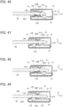
FIG. 45 is a cross-sectional view corresponding to line E-E ofFIG. 44 and showing the connector ofEmbodiment 4 at an early stage of insertion of the second terminal. -
FIG. 46 is a cross-sectional view corresponding to line F-F ofFIG. 44 and showing the connector ofEmbodiment 4 at an early stage of insertion of the second terminal. -
FIG. 47 is a cross-sectional view corresponding to line E-E ofFIG. 44 and showing the connector ofEmbodiment 4 in the process of insertion of the second terminal. -
FIG. 48 is a cross-sectional view corresponding to line F-F ofFIG. 44 and showing the connector ofEmbodiment 4 in the process of insertion of the second terminal. -
FIG. 49 is a cross-sectional view corresponding to line E-E ofFIG. 44 and showing the connector ofEmbodiment 4 with the second terminal being inserted to a connection completion position. -
FIG. 50 is a cross-sectional view corresponding to line F-F ofFIG. 44 and showing the connector ofEmbodiment 4 with the second terminal being inserted to a connection completion position. -
FIG. 51 is a side view showing a conventional connector. - Embodiments of the present invention are described below based on the accompanying drawings.
-
FIG. 1 shows a connector according toEmbodiment 1. The connector includes afirst terminal 11 and asecond terminal 12. To thefirst terminal 11, a springmember retaining portion 13 is attached, and thefirst terminal 11 and the springmember retaining portion 13 constitute a first terminal structure S1. - The
first terminal 11 and thesecond terminal 12 are each made of a conductive material such as metal and have a flat plate shape. - The
second terminal 12 is inserted in the first terminal structure S1 to be thereby electrically connected to thefirst terminal 11. - For convenience, the
first terminal 11 and thesecond terminal 12 both of flat plate shape are defined as extending along a YZ plane, while the direction in which thesecond terminal 12 is inserted into the first terminal structure S1 is defined as a +Z direction, and the direction perpendicular to thefirst terminal 11 and thesecond terminal 12 as a X direction. -
FIG. 2 shows the first terminal structure S1. InFIG. 2 , the springmember retaining portion 13 is illustrated by dashed lines to show an interior of the springmember retaining portion 13. - The spring
member retaining portion 13 is constituted of a plate member such as a metal plate being bent, and has a substantially polygonal tube shape whose central axis extends along the Y direction. Specifically, the springmember retaining portion 13 includes abottom plate portion 13A situated on the -X direction side and extending along a YZ plane, atop plate portion 13B situated on the +X direction side and extending along a YZ plane, afront plate portion 13C situated on the -Z direction side and extending along an XY plane, and arear plate portion 13D situated on the +Z direction side and extending along an XY plane. - The
front plate portion 13C is provided with anopening 13E into which thesecond terminal 12 is to be inserted. Aspring member 13F extending while being bent in the -X direction and the +Z direction is formed at the -Z directional end of thetop plate portion 13B. At a tip portion of thespring member 13F, apressing portion 13G is formed to extend in the Y direction and protrude toward the -X direction. - As shown in
FIG. 3 , the height of thetop plate portion 13B in the X direction from thebottom plate portion 13A has a larger dimension than the thickness of thefirst terminal 11 in the X direction, and the springmember retaining portion 13 is attached to thefirst terminal 11 in such a manner that thefirst terminal 11 is situated inside the springmember retaining portion 13 and in contact with thebottom plate portion 13A of the springmember retaining portion 13. - The +X directional surface of the
first terminal 11 constitutes a first opposingsurface 11A opposing thesecond terminal 12, and between the first opposingsurface 11A of thefirst terminal 11 and thespring member 13F, formed is a secondterminal accommodation portion 13H in which thesecond terminal 12 is inserted. - As shown in
FIG. 4 , the first opposingsurface 11A of thefirst terminal 11 is provided with threefirst protrusion portions 11B each projecting toward the +X direction. The threefirst protrusion portions 11B are arranged at three vertexes of an isosceles triangle T1 having a symmetrical shape with respect to the Z direction, and a first contact portion P1 is formed at a top part, facing in the +X direction, of eachfirst protrusion portion 11B. - The first opposing
surface 11A of thefirst terminal 11 is also provided with twoprojections 11C each projecting in the +X direction. The twoprojections 11C are separately arranged on two sides of the isosceles triangle T1, the two sides having the same length. Specifically, eachprojection 11C is situated at a center part of the relevant side of the isosceles triangle T1 and is so situated as not to overlap the three first contact portions P1 in the Z direction, i.e., insertion direction of thesecond terminal 12. - The projection height of the two
projections 11C from the first opposingsurface 11A is higher than the projection height of the threefirst protrusion portions 11B from the first opposingsurface 11A, and a top part in the +X direction of eachprojection 11C is situated on the +X direction side from the first contact portion P1. - The three
first protrusion portions 11B and the twoprojections 11C can be formed by subjecting thefirst terminal 11 to press working, and the back surface on the -X direction side of thefirst terminal 11 is thus provided with five recesses corresponding to thefirst protrusion portions 11B and theprojections 11C as shown inFIG. 5 . That is, the twoprojections 11C are integrally formed with the first opposingsurface 11A. - As shown in
FIG. 6 , the front surface on the +X direction side of thesecond terminal 12 constitutes a spring member-opposingsurface 12A opposing thespring member 13F when thesecond terminal 12 is inserted in the secondterminal accommodation portion 13H of the first terminal structure S1, and the spring member-opposingsurface 12A is provided with a pressedportion 12B projecting toward the +X direction. The pressedportion 12B has a shape elongated along the Y direction. - In addition, as shown in
FIG. 7 , the back surface on the -X direction side of thesecond terminal 12 constitutes a second opposingsurface 12C opposing the first opposingsurface 11A of thefirst terminal 11 when thesecond terminal 12 is inserted in the secondterminal accommodation portion 13H of the first terminal structure S1, and the second opposingsurface 12C is provided with aprojection accommodation portion 12D of recess shape recessed toward the +X direction. - The
projection accommodation portion 12D is elongated along the Y direction and has a size with which the twoprojections 11C of thefirst terminal 11 can be together accommodated therein. Further, theprojection accommodation portion 12D has a depth dimension larger than the height difference in the X direction between the top parts of theprojections 11C and the first contact portion P1 of thefirst terminal 11. - The pressed
portion 12B and theprojection accommodation portion 12D can be simultaneously formed by a single step of subjecting thesecond terminal 12 to press working, and are arranged at the same position in a YZ plane. - Next, the operation of the connector according to
Embodiment 1 is described. - To electrically connect the
second terminal 12 to thefirst terminal 11, thesecond terminal 12 shown inFIG. 1 is moved in the +Z direction from the -Z direction, and the tip end of thesecond terminal 12 is inserted into the springmember retaining portion 13 through theopening 13E of the springmember retaining portion 13 of the first terminal structure S1 as shown inFIG. 8 . - In this process, as shown in
FIG. 9 , the +Z directional tip end of thesecond terminal 12 is inserted in the +Z direction as passing between thefirst terminal 11 and thespring member 13F, and the top parts of the twoprojections 11C of thefirst terminal 11 are situated on the +X direction side from the first contact portions P1. Hence, the second opposingsurface 12C, facing in the -X direction, of thesecond terminal 12 is situated over the top parts of the twoprojections 11C without making contact with the first contact portions P1, and the spring member-opposingsurface 12A, facing in the +X direction, of thesecond terminal 12 makes contact with thepressing portion 13G of thespring member 13F to elastically compress thespring member 13F toward the +X direction. - In this state, the
second terminal 12 is inserted in the secondterminal accommodation portion 13H formed between thespring member 13F and the first opposingsurface 11A of thefirst terminal 11. - In the state as shown in
FIG. 9 , the pressedportion 12B projecting in the +X direction from the spring member-opposingsurface 12A of thesecond terminal 12 is situated on the -Z direction side from thepressing portion 13G of thespring member 13F and is thus not in contact with thepressing portion 13G yet. - When the
second terminal 12 is inserted further in the +Z direction, as shown inFIG. 10 , with the second opposingsurface 12C of thesecond terminal 12 being kept over the top parts of the twoprojections 11C of thefirst terminal 11, the pressedportion 12B of thesecond terminal 12 makes contact with thepressing portion 13G of thespring member 13F, and thepressing portion 13G rides on the pressedportion 12B projecting in the +X direction from the spring member-opposingsurface 12A of thesecond terminal 12. - In this state, when insertion of the
second terminal 12 in the +Z direction continues, as shown inFIG. 11 , with thepressing portion 13G of thespring member 13F being kept on the pressedportion 12B of thesecond terminal 12, theprojection accommodation portion 12D formed in the second opposingsurface 12C of thesecond terminal 12 is situated on the +X direction side from the twoprojections 11C of thefirst terminal 11 and accommodates the twoprojections 11C. The position of thesecond terminal 12 in the secondterminal accommodation portion 13H at this time is called "connection completion position." - Since the
projection accommodation portion 12D of thesecond terminal 12 has a depth dimension larger than the height difference in the X direction between the top parts of theprojections 11C and the first contact portions P1 of thefirst terminal 11, when thesecond terminal 12 is disposed at the connection completion position and the twoprojections 11C are thus accommodated in theprojection accommodation portion 12D, a predetermined gap is formed between the top part of eachprojection 11C and the bottom part of theprojection accommodation portion 12D, and the second opposingsurface 12C of thesecond terminal 12 makes contact with the three first contact portions P1 of thefirst terminal 11. - At this time, three places in the second opposing
surface 12C at which the three first contact portions P1 are in contact therewith each form a second contact portion P2 in thesecond terminal 12. - Since the
pressing portion 13G of thespring member 13F is positioned on the pressedportion 12B of thesecond terminal 12 as shown inFIG. 11 , thesecond terminal 12 is pressed against thefirst terminal 11 by thespring member 13F via the pressedportion 12B, and the first contact portions P1 and the second contact portions P2 make contact with each other with a predetermined contact pressure, whereby thefirst terminal 11 and thesecond terminal 12 are electrically connected to each other. - As described above, during the process of inserting the
second terminal 12 to the connection completion position, the second opposingsurface 12C of thesecond terminal 12 is in contact only with the top parts of the twoprojections 11C of thefirst terminal 11, and when thesecond terminal 12 is disposed at the connection completion position and the twoprojections 11C are accommodated in theprojection accommodation portion 12D, the second opposingsurface 12C of thesecond terminal 12 makes contact with the three first contact portions P1 of thefirst terminal 11 for the first time. - Moreover, since the two
projections 11C of thefirst terminal 11 are so situated as not to overlap the three first contact portions P1 in the Z direction, i.e., insertion direction of thesecond terminal 12, the three first contact portions P1 of thefirst terminal 11 make contact with the three second contact portions P2 of thesecond terminal 12 without being rubbed by any part of thesecond terminal 12. Similarly, the three second contact portions P2 of thesecond terminal 12 make contact with the three first contact portions P1 of thefirst terminal 11 without being rubbed by any part of thefirst terminal 11. - Hence, it is possible to largely suppress wear of the first contact portions P1 and the second contact portions P2 in the process of insertion of the
second terminal 12 into the secondterminal accommodation portion 13H to thereby electrically connect thefirst terminal 11 and thesecond terminal 12 to each other with high reliability. -
FIG. 12 shows a connector according toEmbodiment 2. The connector includes afirst terminal 21 and asecond terminal 22. To thefirst terminal 21, the springmember retaining portion 13 is attached, and thefirst terminal 21 and the springmember retaining portion 13 constitute a first terminal structure S2. - The
first terminal 21 and thesecond terminal 22 are each made of a conductive material such as metal and have a flat plate shape. - The
second terminal 22 is inserted in the first terminal structure S2 to be thereby electrically connected to thefirst terminal 21. - The spring
member retaining portion 13 is the same as the springmember retaining portion 13 used in the first terminal structure S1 inEmbodiment 1. - As shown in
FIG. 13 , the springmember retaining portion 13 is attached to thefirst terminal 21 in such a manner that thefirst terminal 21 is situated inside the springmember retaining portion 13 and in contact with thebottom plate portion 13A of the springmember retaining portion 13. - The +X directional surface of the
first terminal 21 constitutes a first opposingsurface 21A opposing thesecond terminal 22, and between the first opposingsurface 21A of thefirst terminal 21 and thespring member 13F, formed is the secondterminal accommodation portion 13H in which thesecond terminal 22 is inserted. - As shown in
FIG. 14 , the first opposingsurface 21A of thefirst terminal 21 is provided with twoprojections 21C each projecting in the +X direction. The twoprojections 21C are aligned in the Y direction. - The two
projections 21C can be formed by subjecting thefirst terminal 21 to press working, and the back surface on the -X direction side of thefirst terminal 21 is thus provided with two recesses corresponding to the twoprojections 21C as shown inFIG. 15 . That is, the twoprojections 21C are formed as a result of deformation of the first opposingsurface 21A through press working. - As shown in
FIG. 16 , the front surface on the +X direction side of thesecond terminal 22 constitutes a spring member-opposingsurface 22A opposing thespring member 13F when thesecond terminal 22 is inserted in the secondterminal accommodation portion 13H of the first terminal structure S2, and the spring member-opposingsurface 22A is provided with a pressedportion 22B projecting toward the +X direction. The pressedportion 22B has a shape elongated along the Y direction. - In addition, as shown in
FIG. 17 , the back surface on the -X direction side of thesecond terminal 22 constitutes a second opposingsurface 22C opposing the first opposingsurface 21A of thefirst terminal 21 when thesecond terminal 22 is inserted in the secondterminal accommodation portion 13H of the first terminal structure S2, and the second opposingsurface 22C is provided with aprojection accommodation portion 22D of recess shape recessed toward the +X direction. - The
projection accommodation portion 22D is elongated along the Y direction and has a size with which the twoprojections 21C of thefirst terminal 21 can be together accommodated therein. - The pressed
portion 22B and theprojection accommodation portion 22D can be simultaneously formed by a single step of subjecting thesecond terminal 22 to press working, and are arranged at the same position in a YZ plane. - In addition, the second opposing
surface 22C of thesecond terminal 22 is provided with threesecond protrusion portions 22E each projecting toward the -X direction. The threesecond protrusion portions 22E are arranged at three vertexes of an isosceles triangle T2 having a symmetrical shape with respect to the Z direction, and a second contact portion P2 is formed at a top part, facing in the -X direction, of eachsecond protrusion portion 22E. - When the
second terminal 22 is inserted in the secondterminal accommodation portion 13H of the first terminal structure S2, the twoprojections 21C of thefirst terminal 21 are accommodated in theprojection accommodation portion 22D, while the three second contact portions P2 are so situated as not to overlap the twoprojections 21C in the Z direction, i.e., insertion direction of thesecond terminal 22. - The projection height of the two
projections 21C of the first terminal 21 from the first opposingsurface 21A is set higher than the height of the three second contact portions P2 from the second opposingsurface 22C in thesecond terminal 22. - Further, the
projection accommodation portion 22D of thesecond terminal 22 has a depth dimension larger than the difference between the projection height of theprojections 21C of the first terminal 21 from the first opposingsurface 21A and the height of the second contact portions P2 of the second terminal 22 from the second opposingsurface 22C. - Next, the operation of the connector according to
Embodiment 2 is described. - To electrically connect the
second terminal 22 to thefirst terminal 21, thesecond terminal 22 shown inFIG. 12 is moved in the +Z direction from the -Z direction, and the tip end of thesecond terminal 22 is inserted into the springmember retaining portion 13 through theopening 13E of the springmember retaining portion 13 of the first terminal structure S2 as shown inFIG. 18 . - At this time, as shown in
FIG. 19 , since the projection height of theprojection 21C of the first terminal 21 from the first opposingsurface 21A is higher than the height of the second contact portion P2 of the second terminal 22 from the second opposingsurface 22C, the second contact portion P2 of thesecond terminal 22 does not make contact with the first opposingsurface 21A of thefirst terminal 21, and the second opposingsurface 22C of thesecond terminal 22 is situated over the top part of theprojection 21C of thefirst terminal 21. - The spring member-opposing
surface 22A, facing in the +X direction, of thesecond terminal 22 makes contact with thepressing portion 13G of thespring member 13F to elastically compress thespring member 13F toward the +X direction. - In this state, the
second terminal 22 is inserted in the secondterminal accommodation portion 13H formed between thespring member 13F and the first opposingsurface 21A of thefirst terminal 21. - In the state as shown in
FIG. 19 , the pressedportion 22B of thesecond terminal 22 is situated on the -Z direction side from thepressing portion 13G of thespring member 13F and is thus not in contact with thepressing portion 13G yet. - When the
second terminal 22 is inserted further in the +Z direction, as shown inFIG. 20 , with the second opposingsurface 22C of thesecond terminal 22 being kept over the top parts of the twoprojections 21C of thefirst terminal 21, the pressedportion 22B of thesecond terminal 22 makes contact with thepressing portion 13G of thespring member 13F, and thepressing portion 13G rides on the pressedportion 22B projecting in the +X direction from the spring member-opposingsurface 22A of thesecond terminal 22. - In this state, when insertion of the
second terminal 22 in the +Z direction continues, as shown inFIG. 21 , with thepressing portion 13G of thespring member 13F being kept on the pressedportion 22B of thesecond terminal 22, theprojection accommodation portion 22D formed in the second opposingsurface 22C of thesecond terminal 22 is situated on the +X direction side from the twoprojections 21C of thefirst terminal 21 and accommodates the twoprojections 21C. The position of thesecond terminal 22 in the secondterminal accommodation portion 13H at this time is called "connection completion position." - Since the
projection accommodation portion 22D of thesecond terminal 22 has a depth dimension larger than the difference between the projection height of theprojections 21C of the first terminal 21 from the first opposingsurface 21A and the height of the second contact portions P2 of the second terminal 22 from the second opposingsurface 22C, when thesecond terminal 22 is disposed at the connection completion position and the twoprojections 21C are thus accommodated in theprojection accommodation portion 22D, a predetermined gap is formed between the top part of eachprojection 21C and the bottom part of theprojection accommodation portion 22D, and the three second contact portions P2 of thesecond terminal 22 make contact with the first opposingsurface 21A of thefirst terminal 21. - At this time, three places in the first opposing
surface 21A at which the three second contact portions P2 are in contact therewith each form the first contact portion P1 in thefirst terminal 21. - Since the
pressing portion 13G of thespring member 13F is positioned on the pressedportion 22B of thesecond terminal 22 as shown inFIG. 21 , thesecond terminal 22 is pressed against thefirst terminal 21 by thespring member 13F via the pressedportion 22B, and the first contact portions P1 and the second contact portions P2 make contact with each other with a predetermined contact pressure, whereby thefirst terminal 21 and thesecond terminal 22 are electrically connected to each other. - As described above, during the process of inserting the
second terminal 22 to the connection completion position, the first opposingsurface 21A of thefirst terminal 21 is not in contact with any part of thesecond terminal 22, and when thesecond terminal 22 is disposed at the connection completion position and the twoprojections 21C are accommodated in theprojection accommodation portion 22D, the three second contact portions P2 of thesecond terminal 22 make contact with the first opposingsurface 21A of thefirst terminal 21 for the first time. - Moreover, since the two
projections 21C of thefirst terminal 21 are so situated as not to overlap the three second contact portions P2 of thesecond terminal 22 in the Z direction, i.e., insertion direction of thesecond terminal 22, the three second contact portions P2 of thesecond terminal 22 make contact with the three first contact portions P1 of thefirst terminal 21 without being rubbed by any part of thefirst terminal 21. Similarly, the three first contact portions P1 of thefirst terminal 21 make contact with the three second contact portions P2 of thesecond terminal 22 without being rubbed by any part of thesecond terminal 22. - Hence, as with
Embodiment 1, it is also possible in the connector according toEmbodiment 2 to largely suppress wear of the first contact portions P1 and the second contact portions P2 in the process of insertion of thesecond terminal 22 into the secondterminal accommodation portion 13H to thereby electrically connect thefirst terminal 21 and thesecond terminal 22 to each other with high reliability. -
FIG. 22 shows a connector according toEmbodiment 3. The connector includes afirst terminal 31 and asecond terminal 32. To thefirst terminal 31, the springmember retaining portion 13 is attached, and thefirst terminal 31 and the springmember retaining portion 13 constitute a first terminal structure S3. - The
first terminal 31 and thesecond terminal 32 are each made of a conductive material such as metal and have a flat plate shape. - The
second terminal 32 is inserted in the first terminal structure S3 to be thereby electrically connected to thefirst terminal 31. - The spring
member retaining portion 13 is the same as the springmember retaining portion 13 used in the first terminal structure S1 inEmbodiment 1. - As shown in
FIG. 23 , the springmember retaining portion 13 is attached to thefirst terminal 31 in such a manner that thefirst terminal 31 is situated inside the springmember retaining portion 13 and in contact with thebottom plate portion 13A of the springmember retaining portion 13. - The +X directional surface of the
first terminal 31 constitutes a first opposingsurface 31A opposing thesecond terminal 32, and between the first opposingsurface 31A of thefirst terminal 31 and thespring member 13F, formed is the secondterminal accommodation portion 13H in which thesecond terminal 32 is inserted. - As shown in
FIG. 24 , the first opposingsurface 31A of thefirst terminal 31 is provided with threefirst protrusion portions 31B each projecting toward the +X direction. The threefirst protrusion portions 31B are arranged at three vertexes of an isosceles triangle T3 having a symmetrical shape with respect to the Z direction, and a first contact portion P1 is formed at a top part, facing in the +X direction, of eachfirst protrusion portion 31B. - The first opposing
surface 31A of thefirst terminal 31 is also provided with twoprojections 31C each projecting in the +X direction. The twoprojections 31C are arranged outside the isosceles triangle T3. Specifically, theprojections 31C are separately situated on the +Y direction side and the -Y direction side from the isosceles triangle T3 with a distance therebetween in the Y direction, and are so situated as not to overlap the three first contact portions P1 in the Z direction, i.e., insertion direction of thesecond terminal 32. - The projection height of the two
projections 31C from the first opposingsurface 31A is higher than the projection height of the threefirst protrusion portions 31B from the first opposingsurface 31A, and a top part in the +X direction of eachprojection 31C is situated on the +X direction side from the first contact portion P1. - The three
first protrusion portions 31B and the twoprojections 31C can be formed by subjecting thefirst terminal 31 to press working, and the back surface on the -X direction side of thefirst terminal 31 is thus provided with five recesses corresponding to thefirst protrusion portions 31B and theprojections 31C as shown inFIG. 25 . - As shown in
FIG. 26 , the front surface on the +X direction side of thesecond terminal 32 constitutes a spring member-opposingsurface 32A opposing thespring member 13F when thesecond terminal 32 is inserted in the secondterminal accommodation portion 13H of the first terminal structure S3, and the spring member-opposingsurface 32A is provided with two pressedportions 32B projecting toward the +X direction. The two pressedportions 32B are aligned in the Y direction and disposed with a distance therebetween in the Y direction. - In addition, as shown in
FIG. 27 , the back surface on the -X direction side of thesecond terminal 32 constitutes a second opposingsurface 32C opposing the first opposingsurface 31A of thefirst terminal 31 when thesecond terminal 32 is inserted in the secondterminal accommodation portion 13H of the first terminal structure S3, and the second opposingsurface 32C is provided with twoprojection accommodation portions 32D of recess shape recessed toward the +X direction. - The two
projection accommodation portions 32D are aligned in the Y direction and disposed with a distance therebetween in the Y direction. The distance in the Y direction between the twoprojection accommodation portions 32D is set equal to the distance in the Y direction between the twoprojections 31C of thefirst terminal 31. In addition, eachprojection accommodation portion 32D has a size with which theprojection 31C of thefirst terminal 31 can be accommodated therein. - Moreover, the two
projection accommodation portions 32D each have a depth dimension larger than the height difference in the X direction between the top part of theprojection 31C and the first contact portion P1 of thefirst terminal 31. - The two pressed
portions 32B and the twoprojection accommodation portions 32D can be simultaneously formed by a single step of subjecting thesecond terminal 32 to press working, and are arranged at the same positions in a YZ plane. - Next, the operation of the connector according to
Embodiment 3 is described. - To electrically connect the
second terminal 32 to thefirst terminal 31, thesecond terminal 32 shown inFIG. 22 is moved in the +Z direction from the -Z direction, and the tip end of thesecond terminal 32 is inserted into the springmember retaining portion 13 through theopening 13E of the springmember retaining portion 13 of the first terminal structure S3 as shown inFIG. 28 . - In this process, as shown in
FIGS. 29 and30 , the +Z directional tip end of thesecond terminal 32 is inserted in the +Z direction as passing between thefirst terminal 31 and thespring member 13F, and the top parts of the twoprojections 31C of thefirst terminal 31 are situated on the +X direction side from the first contact portions P1. Hence, the second opposingsurface 32C, facing in the -X direction, of thesecond terminal 32 is situated over the top parts of the twoprojections 31C without making contact with the first contact portions P1, and the spring member-opposingsurface 32A, facing in the +X direction, of thesecond terminal 32 makes contact with thepressing portion 13G of thespring member 13F to elastically compress thespring member 13F toward the +X direction. - In this state, the
second terminal 32 is inserted in the secondterminal accommodation portion 13H formed between thespring member 13F and the first opposingsurface 31A of thefirst terminal 31. - In the state as shown in
FIGS. 29 and30 , the pressedportions 32B projecting in the +X direction from the spring member-opposingsurface 32A of thesecond terminal 32 are situated on the -Z direction side from thepressing portion 13G of thespring member 13F and are thus not in contact with thepressing portion 13G yet. - When the
second terminal 32 is inserted further in the +Z direction, as shown inFIGS. 31 and 32 , with the second opposingsurface 32C of thesecond terminal 32 being kept over the top parts of the twoprojections 31C of thefirst terminal 31, the pressedportions 32B of thesecond terminal 32 make contact with thepressing portion 13G of thespring member 13F, and thepressing portion 13G rides on the pressedportions 32B projecting in the +X direction from the spring member-opposingsurface 32A of thesecond terminal 32. - In this state, when insertion of the
second terminal 32 in the +Z direction continues, as shown inFIGS. 33 and34 , with thepressing portion 13G of thespring member 13F being kept on the pressedportions 32B of thesecond terminal 32, theprojection accommodation portions 32D formed in the second opposingsurface 32C of thesecond terminal 32 are situated on the +X direction side from the twoprojections 31C of thefirst terminal 31 and separately accommodate the twoprojections 31C. The position of thesecond terminal 32 in the secondterminal accommodation portion 13H at this time is called "connection completion position." - Since the
projection accommodation portions 32D of thesecond terminal 32 have a depth dimension larger than the height difference in the X direction between the top parts of theprojections 31C and the first contact portions P1 of thefirst terminal 31, when thesecond terminal 32 is disposed at the connection completion position and the twoprojections 31C are thus accommodated in theprojection accommodation portions 32D, a predetermined gap is formed between the top part of eachprojection 31C and the bottom part of eachprojection accommodation portion 32D, and the second opposingsurface 32C of thesecond terminal 32 makes contact with the three first contact portions P1 of thefirst terminal 31. - At this time, three places in the second opposing
surface 32C at which the three first contact portions P1 are in contact therewith each form a second contact portion P2 in thesecond terminal 32. - Since the
pressing portion 13G of thespring member 13F is positioned on the pressedportions 32B of thesecond terminal 32 as shown inFIGS. 33 and34 , thesecond terminal 32 is pressed against thefirst terminal 31 by thespring member 13F via the pressedportions 32B, and the first contact portions P1 and the second contact portions P2 make contact with each other with a predetermined contact pressure, whereby thefirst terminal 31 and thesecond terminal 32 are electrically connected to each other. - As described above, during the process of inserting the
second terminal 32 to the connection completion position, the second opposingsurface 32C of thesecond terminal 32 is in contact only with the top parts of the twoprojections 31C of thefirst terminal 31, and when thesecond terminal 32 is disposed at the connection completion position and the twoprojections 31C are accommodated in theprojection accommodation portions 32D, the second opposingsurface 32C of thesecond terminal 32 makes contact with the three first contact portions P1 of thefirst terminal 31 for the first time. - Moreover, since the two
projections 31C of thefirst terminal 31 are so situated as not to overlap the three first contact portions P1 in the Z direction, i.e., insertion direction of thesecond terminal 32, the three first contact portions P1 of thefirst terminal 31 make contact with the three second contact portions P2 of thesecond terminal 32 without being rubbed by any part of thesecond terminal 32. Similarly, the three second contact portions P2 of thesecond terminal 32 make contact with the three first contact portions P1 of thefirst terminal 31 without being rubbed by any part of thefirst terminal 31. - Hence, as with
Embodiments Embodiment 3 to largely suppress wear of the first contact portions P1 and the second contact portions P2 in the process of insertion of thesecond terminal 32 into the secondterminal accommodation portion 13H to thereby electrically connect thefirst terminal 31 and thesecond terminal 32 to each other with high reliability. -
FIG. 35 shows a connector according toEmbodiment 4. The connector includes afirst terminal 41 and asecond terminal 42. To thefirst terminal 41, aprojection forming component 51 and the springmember retaining portion 13 are attached, and thefirst terminal 41, theprojection forming component 51, and the springmember retaining portion 13 constitute a first terminal structure S4. - The
first terminal 41 and thesecond terminal 42 are each made of a conductive material such as metal and have a flat plate shape. - The
second terminal 42 is inserted in the first terminal structure S4 to be thereby electrically connected to thefirst terminal 41. - The spring
member retaining portion 13 is the same as the springmember retaining portion 13 used in the first terminal structure S1 inEmbodiment 1. - As shown in
FIG. 36 , the springmember retaining portion 13 is attached to thefirst terminal 41 in such a manner that thefirst terminal 41 is situated inside the springmember retaining portion 13 and in contact with thebottom plate portion 13A of the springmember retaining portion 13. - The +X directional surface of the
first terminal 41 constitutes a first opposingsurface 41A opposing thesecond terminal 42, theprojection forming component 51 is attached on the first opposingsurface 41A in such a manner that part of the first opposingsurface 41A is exposed, and between the exposed part of the first opposing surface 41Atogether with theprojection forming component 51 and thespring member 13F, formed is the secondterminal accommodation portion 13H in which thesecond terminal 42 is inserted. -
FIG. 37 shows thefirst terminal 41 to which theprojection forming component 51 is attached. Theprojection forming component 51 has a frame shape, and part of the first opposingsurface 41A of thefirst terminal 41 is exposed through an inner part of theprojection forming component 51. - As shown in
FIG. 38 , the first opposingsurface 41A of thefirst terminal 41 is provided with threefirst protrusion portions 41B each projecting toward the +X direction. The threefirst protrusion portions 41B are arranged at three vertexes of an isosceles triangle T4 having a symmetrical shape with respect to the Z direction, and a first contact portion P1 is formed at a top part, facing in the +X direction, of eachfirst protrusion portion 41B. - The three
first protrusion portions 41B can be formed by subjecting thefirst terminal 41 to press working, and the back surface on the -X direction side of thefirst terminal 41 is thus provided with three recesses corresponding to thefirst protrusion portions 41B as shown inFIG. 39 . - The
projection forming component 51 is formed of a metal plate cut out in a frame shape and bent as shown inFIG. 40 , and includes aframe shape portion 51A extending along a YZ plane and twotubular portions 51B joined to theframe shape portion 51A. The twotubular portions 51B are each formed by bending the metal plate constituting theprojection forming component 51 into a tubular shape about a center axis extending in the Y direction, are aligned in the Y direction, and are disposed with a distance therebetween in the Y direction. The twotubular portions 51B form twoprojections 51C each projecting in the +X direction. - At a center part in the Y direction of each
tubular portion 51B, acutout 51D is formed by cutting out a +X directional part of thetubular portion 51B. - With the two
tubular portions 51B being disposed with a distance therebetween in the Y direction, and eachtubular portion 51B being provided with thecutout 51D, it is configured such that, as shown inFIG. 37 , theprojections 51C are so situated as not to overlap the three first contact portions P1 of thefirst terminal 41 in the Z direction, i.e., insertion direction of thesecond terminal 42 when theprojection forming component 51 is attached to the first opposingsurface 41A of thefirst terminal 41. - The projection height, from the first opposing
surface 41A, of theprojections 51C formed of theprojection forming component 51 is higher than the height of the three first contact portions P1 from the first opposingsurface 31A, and a top part in the +X direction of eachprojection 51C is situated on the +X direction side from the first contact portion P1. - The
projection forming component 51 as above can be attached to the first opposingsurface 41A of thefirst terminal 41 by, for example, welding. - As shown in
FIG. 42 , the front surface on the +X direction side of thesecond terminal 42 constitutes a spring member-opposingsurface 42A opposing thespring member 13F when thesecond terminal 42 is inserted in the secondterminal accommodation portion 13H of the first terminal structure S4, and the spring member-opposingsurface 42A is provided with two pressedportions 42B projecting toward the +X direction. The two pressedportions 42B are aligned in the Y direction and disposed with a distance therebetween in the Y direction. - In addition, as shown in
FIG. 43 , the back surface on the -X direction side of thesecond terminal 42 constitutes a second opposingsurface 42C opposing the first opposingsurface 41A of thefirst terminal 41 when thesecond terminal 42 is inserted in the secondterminal accommodation portion 13H of the first terminal structure S4, and the second opposingsurface 42C is provided with twoprojection accommodation portions 42D of recess shape recessed toward the +X direction. - The two
projection accommodation portions 42D are aligned in the Y direction and disposed with a distance therebetween in the Y direction. The twoprojection accommodation portions 42D each have a size and have a Y directional distance therebetween with which the twoprojections 51C of theprojection forming component 51 attached to thefirst terminal 41 can be separately accommodated therein. - Moreover, the two
projection accommodation portions 42D each have a depth dimension larger than the height difference in the X direction between the +X directional top part of eachprojection 51C of theprojection forming component 51 and the first contact portion P1 of thefirst terminal 41. - In addition, the two pressed
portions 42B of thesecond terminal 42 and the twoprojection accommodation portions 42D can be simultaneously formed by a single step of subjecting thesecond terminal 42 to press working, and are arranged at the same positions in a YZ plane. - Next, the operation of the connector according to
Embodiment 4 is described. - To electrically connect the
second terminal 42 to thefirst terminal 41, thesecond terminal 42 shown inFIG. 35 is moved in the +Z direction from the -Z direction, and the tip end of thesecond terminal 42 is inserted into the springmember retaining portion 13 through theopening 13E of the springmember retaining portion 13 of the first terminal structure S4 as shown inFIG. 44 . - In this process, as shown in
FIGS. 45 and46 , the +Z directional tip end of thesecond terminal 42 is inserted in the +Z direction as passing between theprojection forming component 51 and thespring member 13F, and the +X directional top parts of the twoprojections 51C of theprojection forming component 51 are situated on the +X direction side from the first contact portions P1. Hence, the second opposingsurface 42C, facing in the -X direction, of thesecond terminal 42 is situated over the top parts of the twoprojections 51C without making contact with the first contact portions P1, and the spring member-opposingsurface 42A, facing in the +X direction, of thesecond terminal 42 makes contact with thepressing portion 13G of thespring member 13F to elastically compress thespring member 13F toward the +X direction. - In this state, the
second terminal 42 is inserted in the secondterminal accommodation portion 13H formed between thespring member 13F and the first opposingsurface 41A of thefirst terminal 41 together with theprojection forming component 51. - In the state as shown in
FIGS. 45 and46 , the pressedportions 42B projecting in the +X direction from the spring member-opposingsurface 42A of thesecond terminal 42 are situated on the -Z direction side from thepressing portion 13G of thespring member 13F and are thus not in contact with thepressing portion 13G yet. - When the
second terminal 42 is inserted further in the +Z direction, as shown inFIGS. 47 and 48 , with the second opposingsurface 42C of thesecond terminal 42 being kept over the top parts of the twoprojections 51C of theprojection forming component 51, the pressedportions 42B of thesecond terminal 42 make contact with thepressing portion 13G of thespring member 13F, and thepressing portion 13G rides on the pressedportions 42B projecting in the +X direction from the spring member-opposingsurface 42A of thesecond terminal 42. - In this state, when insertion of the
second terminal 42 in the +Z direction continues, as shown inFIGS. 49 and50 , with thepressing portion 13G of thespring member 13F being kept on the pressedportions 42B of thesecond terminal 42, theprojection accommodation portions 42D formed in the second opposingsurface 42C of thesecond terminal 42 are situated on the +X direction side from the twoprojections 51C of theprojection forming component 51 and separately accommodate the twoprojections 51C. The position of thesecond terminal 42 in the secondterminal accommodation portion 13H at this time is called "connection completion position." - Since the
projection accommodation portions 42D of thesecond terminal 42 have a depth dimension larger than the height difference in the X direction between the +X directional top parts of theprojections 51C of theprojection forming component 51 and the first contact portions P1 of thefirst terminal 41, when thesecond terminal 42 is disposed at the connection completion position and the twoprojections 51C are thus accommodated in theprojection accommodation portions 42D, a predetermined gap is formed between the top part of eachprojection 51C and the bottom part of eachprojection accommodation portion 42D, and the second opposingsurface 42C of thesecond terminal 42 makes contact with the three first contact portions P1 of thefirst terminal 41. - At this time, three places in the second opposing
surface 42C at which the three first contact portions P1 are in contact therewith each form a second contact portion P2 in thesecond terminal 42. - Since the
pressing portion 13G of thespring member 13F is positioned on the pressedportions 42B of thesecond terminal 42 as shown inFIGS. 49 and50 , thesecond terminal 42 is pressed against thefirst terminal 41 by thespring member 13F via the pressedportions 42B, and the first contact portions P1 and the second contact portions P2 make contact with each other with a predetermined contact pressure, whereby thefirst terminal 41 and thesecond terminal 42 are electrically connected to each other. - As described above, during the process of inserting the
second terminal 42 to the connection completion position, the second opposingsurface 42C of thesecond terminal 42 is in contact only with the top parts of the twoprojections 51C of theprojection forming component 51, and when thesecond terminal 42 is disposed at the connection completion position and the twoprojections 51C are separately accommodated in theprojection accommodation portions 42D, the second opposingsurface 42C of thesecond terminal 42 makes contact with the three first contact portions P1 of thefirst terminal 41 for the first time. - Moreover, since the two
projections 51C of theprojection forming component 51 are so situated as not to overlap the three first contact portions P1 in the Z direction, i.e., insertion direction of thesecond terminal 42, the three first contact portions P1 of thefirst terminal 41 make contact with the three second contact portions P2 of thesecond terminal 42 without being rubbed by any part of thesecond terminal 42. Similarly, the three second contact portions P2 of thesecond terminal 42 make contact with the three first contact portions P1 of thefirst terminal 41 without being rubbed by any part of thefirst terminal 41 and theprojection forming component 51. - Hence, as with
Embodiments 1 to 3, it is also possible in the connector according toEmbodiment 4 to largely suppress wear of the first contact portions P1 and the second contact portions P2 in the process of insertion of thesecond terminal 42 into the secondterminal accommodation portion 13H to thereby electrically connect thefirst terminal 41 and thesecond terminal 42 to each other with high reliability. - In
Embodiments first terminal first protrusion portion first terminal first terminal surface surface first terminal second terminal - With the surface of such rotatable metal ball constituting the first contact portion P1, when the first contact portion P1 makes contact with the
second terminal second terminal first terminal second terminal - In
Embodiments 1 to 4 described above, three first contact portions P1 make contact with three second contact portions P2, but the invention is not limited thereto, and it suffices if one or more first contact portions P1 make contact with one or more second contact portions P2. Meanwhile, the connector is preferably configured such that the three first contact portions P1 make contact with the three second contact portions P2 as inEmbodiments 1 to 4, because thefirst terminal second terminal - In
Embodiments 1 to 4 described above, three first contact portions P1 and three second contact portions P2 are arranged at three vertexes of the isosceles triangle T1 to T4, but the contact portions are not limited to be arranged at vertexes of an isosceles triangle. Meanwhile, the three first contact portions P1 and the three second contact portions P2 are preferably arranged at three vertexes of the isosceles triangle T1 to T4 for positionally stabilizing thefirst terminal second terminal - In addition, in
Embodiments 1 to 4 described above, the twoprojections projections Embodiments 1 to 4 for positionally stabilizing thesecond terminal
Claims (13)
- A connector in which a second terminal (12, 22, 32, 42) of flat plate shape is moved in parallel with and superposed on a first terminal (11, 21, 31, 41) of flat plate shape to thereby connect the first terminal and the second terminal to each other, the connector comprising:a spring member (13F) attached to the first terminal and configured to press the second terminal toward the first terminal;wherein the first terminal includes a first opposing surface (11A, 21A, 31A, 41A) and a first contact portion (P1) facing the second terminal,a second terminal accommodation portion (13H) in which the second terminal is inserted is formed between the first opposing surface and the spring member,the second terminal includes a second opposing surface (12C, 22C, 32C, 42C) opposing the first opposing surface, a second contact portion (P2) facing the first terminal, and a pressed portion (12B, 22B, 32B, 42B) formed on and projecting from a spring member-opposing surface (12A, 22A, 32A, 42A) opposing the spring member,one of the first opposing surface and the second opposing surface is provided with a projection (11C, 21C, 31C, 51C) projecting toward another of the first opposing surface and the second opposing surface, and the another is provided with a projection accommodation portion (12D, 22D, 32D, 42D) of recess shape for accommodating the projection, andwhen the second terminal is inserted along a predetermined insertion direction to a predetermined connection completion position in the second terminal accommodation portion, the projection is accommodated in the projection accommodation portion so that the second terminal is retained at the predetermined connection completion position, the second terminal is pressed against the first terminal by the spring member via the pressed portion, and the first contact portion (P1) and the second contact portion (P2) make contact with each other, whereby the first terminal (11, 21, 31, 41) and the second terminal (12, 22, 32, 42) are electrically connected to each other.
- The connector according to claim 1, wherein when the second terminal is inserted to the predetermined connection completion position, a predetermined gap is formed between a top part of the projection (11C, 21C, 31C, 51C) and a bottom part of the projection accommodation portion (12D, 22D, 32D, 42D).
- The connector according to claim 1 or 2,wherein the first terminal includes a first protrusion portion (11B, 31B, 41B) formed on and projecting from the first opposing surface (11A, 31A, 41A),the first contact portion (P1) is disposed at a top part of the first protrusion portion, andthe second contact portion (P2) is disposed on the second opposing surface (12C, 32C, 42C).
- The connector according to claim 1 or 2,wherein the second terminal includes a second protrusion portion (22E) formed on and projecting from the second opposing surface (22C),the second contact portion (P2) is disposed at a top part of the second protrusion portion, andthe first contact portion (P1) is disposed on the first opposing surface (1 1A).
- The connector according to any one of claims 1-4, wherein the first contact portion (P1) and the second contact portion (P2) are so situated as not to overlap the projection (11C, 21C, 31C, 51C) in the predetermined insertion direction.
- The connector according to claim 5,wherein the first terminal includes a plurality of the first contact portions (P1), andthe second terminal includes a plurality of the second contact portions (P2) corresponding to the plurality of the first contact portions.
- The connector according to claim 6, wherein the plurality of the first contact portions and the plurality of the second contact portions respectively consist of the three first contact portions (P1) and the three second contact portions (P2) separately arranged at vertexes of an isosceles triangle (T1, T2, T3, T4) having a symmetrical shape with respect to the predetermined insertion direction.
- The connector according to claim 7, wherein the projection (11C, 21C, 51C) and the projection accommodation portion (12D, 22D, 42D) are arranged on a side of the isosceles triangle or inside the isosceles triangle (T1, T2, T4).
- The connector according to claim 7, wherein the projection (31C) and the projection accommodation portion (32D) are arranged outside the isosceles triangle (T3).
- The connector according to any one of claims 1-9, wherein the projection (11C, 21C, 31C) is formed integrally with one of the first opposing surface (11A, 21A, 31A) and the second opposing surface (12C, 22C, 32C).
- The connector according to any one of claims 1-3, comprising a projection forming component (51) attached on the first opposing surface in such a manner that the first contact portion is exposed,
wherein the projection (51C) is formed in the projection forming component. - The connector according to any one of claims 1-10, wherein the projection (11C, 21C, 31C) is formed in the first opposing surface (11A, 21A, 31A), the projection accommodation portion (12D, 22D, 32D) is formed in the second opposing surface (12C, 22C, 32C), and the pressed portion (12B, 22B, 32B) is formed at a same position as the projection accommodation portion in the spring member-opposing surface (12A, 22A, 32A).
- The connector according to any one of claims 1-12, comprising a spring member retaining portion (13) attached to the first terminal (11, 21, 31, 41) and retaining the spring member (13F) such that the spring member opposes the first opposing surface (11A).
Applications Claiming Priority (1)
| Application Number | Priority Date | Filing Date | Title |
|---|---|---|---|
| JP2023031701A JP2024123903A (en) | 2023-03-02 | 2023-03-02 | connector |
Publications (2)
| Publication Number | Publication Date |
|---|---|
| EP4425720A1 true EP4425720A1 (en) | 2024-09-04 |
| EP4425720B1 EP4425720B1 (en) | 2025-12-03 |
Family
ID=89535029
Family Applications (1)
| Application Number | Title | Priority Date | Filing Date |
|---|---|---|---|
| EP24151028.8A Active EP4425720B1 (en) | 2023-03-02 | 2024-01-09 | Connector |
Country Status (4)
| Country | Link |
|---|---|
| US (1) | US20240297452A1 (en) |
| EP (1) | EP4425720B1 (en) |
| JP (1) | JP2024123903A (en) |
| CN (1) | CN118589227A (en) |
Families Citing this family (2)
| Publication number | Priority date | Publication date | Assignee | Title |
|---|---|---|---|---|
| JP7686353B2 (en) * | 2021-12-28 | 2025-06-02 | 日本航空電子工業株式会社 | connector |
| JP2024134172A (en) * | 2023-03-20 | 2024-10-03 | 日本圧着端子製造株式会社 | connector |
Citations (4)
| Publication number | Priority date | Publication date | Assignee | Title |
|---|---|---|---|---|
| JP2015222621A (en) | 2014-05-22 | 2015-12-10 | 株式会社オートネットワーク技術研究所 | Connection structure of terminal |
| US20170310032A1 (en) * | 2016-04-21 | 2017-10-26 | Japan Aviation Electronics Industry, Limited | Connector terminal with one or more top side contact portions and three linear bottom side contact portions |
| WO2022185955A1 (en) * | 2021-03-04 | 2022-09-09 | 株式会社オートネットワーク技術研究所 | Terminal unit, female terminal, and male terminal |
| WO2022202446A1 (en) * | 2021-03-26 | 2022-09-29 | 株式会社オートネットワーク技術研究所 | Terminal unit, first terminal, and second terminal |
Family Cites Families (6)
| Publication number | Priority date | Publication date | Assignee | Title |
|---|---|---|---|---|
| JP6634210B2 (en) * | 2014-12-25 | 2020-01-22 | 日本航空電子工業株式会社 | Contact and connector including the same |
| JP6801563B2 (en) * | 2017-04-13 | 2020-12-16 | 株式会社オートネットワーク技術研究所 | Female terminal |
| DE102018215025A1 (en) * | 2018-09-04 | 2020-03-05 | Te Connectivity Germany Gmbh | Electrical contact for mating with a mating contact |
| US12413016B2 (en) * | 2020-11-12 | 2025-09-09 | Autonetworks Technologies, Ltd. | Connector and connector device |
| JP7466844B2 (en) * | 2020-12-11 | 2024-04-15 | 株式会社オートネットワーク技術研究所 | Terminal Unit |
| DE102021112425A1 (en) * | 2021-05-12 | 2022-11-17 | Te Connectivity Germany Gmbh | Vibration resistant high current electrical flat socket contact device |
-
2023
- 2023-03-02 JP JP2023031701A patent/JP2024123903A/en active Pending
- 2023-12-15 CN CN202311737396.3A patent/CN118589227A/en active Pending
-
2024
- 2024-01-09 EP EP24151028.8A patent/EP4425720B1/en active Active
- 2024-02-02 US US18/431,372 patent/US20240297452A1/en active Pending
Patent Citations (4)
| Publication number | Priority date | Publication date | Assignee | Title |
|---|---|---|---|---|
| JP2015222621A (en) | 2014-05-22 | 2015-12-10 | 株式会社オートネットワーク技術研究所 | Connection structure of terminal |
| US20170310032A1 (en) * | 2016-04-21 | 2017-10-26 | Japan Aviation Electronics Industry, Limited | Connector terminal with one or more top side contact portions and three linear bottom side contact portions |
| WO2022185955A1 (en) * | 2021-03-04 | 2022-09-09 | 株式会社オートネットワーク技術研究所 | Terminal unit, female terminal, and male terminal |
| WO2022202446A1 (en) * | 2021-03-26 | 2022-09-29 | 株式会社オートネットワーク技術研究所 | Terminal unit, first terminal, and second terminal |
Also Published As
| Publication number | Publication date |
|---|---|
| JP2024123903A (en) | 2024-09-12 |
| US20240297452A1 (en) | 2024-09-05 |
| CN118589227A (en) | 2024-09-03 |
| EP4425720B1 (en) | 2025-12-03 |
Similar Documents
| Publication | Publication Date | Title |
|---|---|---|
| JP6198712B2 (en) | Circuit board electrical connector | |
| CN116169501B (en) | Terminal and chain terminal | |
| CN109216989B (en) | Connector terminal assembly and connector | |
| JP5859938B2 (en) | Receptacle connector and manufacturing method thereof | |
| JP4207952B2 (en) | connector | |
| EP4425720B1 (en) | Connector | |
| US11211726B2 (en) | Connector and connecting method | |
| CN109004411B (en) | Multi-contact connector | |
| CN112467466B (en) | Connector and connecting method | |
| KR20000034964A (en) | Coaxial connector with switch | |
| CN113675651A (en) | Connector with a locking member | |
| EP0559057A1 (en) | Electrical connector terminal | |
| CN112467440A (en) | Connector and method for manufacturing connector | |
| JP2022059399A (en) | Electrical connector with flat conductor, mating electrical connector, and electrical connector assembly | |
| CN115377719A (en) | Terminal, wire connector and wire-to-board connector | |
| CN112563774B (en) | Connector with a locking member | |
| KR101422907B1 (en) | Electric connector for circuit substrate | |
| KR20130094838A (en) | Connector | |
| CN114447665B (en) | Electrical connector | |
| JPH1032031A (en) | contact | |
| JP2002367695A (en) | Card edge connector | |
| JP2002050420A (en) | Board connector | |
| JP7704805B2 (en) | Terminals | |
| JPH03114153A (en) | Multiple core | |
| CN110212348A (en) | Circuit board electrical connector |
Legal Events
| Date | Code | Title | Description |
|---|---|---|---|
| PUAI | Public reference made under article 153(3) epc to a published international application that has entered the european phase |
Free format text: ORIGINAL CODE: 0009012 |
|
| STAA | Information on the status of an ep patent application or granted ep patent |
Free format text: STATUS: REQUEST FOR EXAMINATION WAS MADE |
|
| 17P | Request for examination filed |
Effective date: 20240109 |
|
| AK | Designated contracting states |
Kind code of ref document: A1 Designated state(s): AL AT BE BG CH CY CZ DE DK EE ES FI FR GB GR HR HU IE IS IT LI LT LU LV MC ME MK MT NL NO PL PT RO RS SE SI SK SM TR |
|
| RAP3 | Party data changed (applicant data changed or rights of an application transferred) |
Owner name: JAPAN AVIATION ELECTRONICS INDUSTRY, LIMITED |
|
| RBV | Designated contracting states (corrected) |
Designated state(s): AL AT BE BG CH CY CZ DE DK EE ES FI FR GB GR HR HU IE IS IT LI LT LU LV MC ME MK MT NL NO PL PT RO RS SE SI SK SM TR |
|
| STAA | Information on the status of an ep patent application or granted ep patent |
Free format text: STATUS: EXAMINATION IS IN PROGRESS |
|
| 17Q | First examination report despatched |
Effective date: 20250115 |
|
| GRAP | Despatch of communication of intention to grant a patent |
Free format text: ORIGINAL CODE: EPIDOSNIGR1 |
|
| STAA | Information on the status of an ep patent application or granted ep patent |
Free format text: STATUS: GRANT OF PATENT IS INTENDED |
|
| GRAS | Grant fee paid |
Free format text: ORIGINAL CODE: EPIDOSNIGR3 |
|
| GRAA | (expected) grant |
Free format text: ORIGINAL CODE: 0009210 |
|
| STAA | Information on the status of an ep patent application or granted ep patent |
Free format text: STATUS: THE PATENT HAS BEEN GRANTED |
|
| INTG | Intention to grant announced |
Effective date: 20251002 |
|
| AK | Designated contracting states |
Kind code of ref document: B1 Designated state(s): AL AT BE BG CH CY CZ DE DK EE ES FI FR GB GR HR HU IE IS IT LI LT LU LV MC ME MK MT NL NO PL PT RO RS SE SI SK SM TR |
|
| REG | Reference to a national code |
Ref country code: CH Ref legal event code: F10 Free format text: ST27 STATUS EVENT CODE: U-0-0-F10-F00 (AS PROVIDED BY THE NATIONAL OFFICE) Effective date: 20251203 Ref country code: GB Ref legal event code: FG4D |
|
| REG | Reference to a national code |
Ref country code: DE Ref legal event code: R096 Ref document number: 602024001433 Country of ref document: DE |
|
| REG | Reference to a national code |
Ref country code: IE Ref legal event code: FG4D |
|
| REG | Reference to a national code |
Ref country code: NL Ref legal event code: MP Effective date: 20251203 |
|
| PG25 | Lapsed in a contracting state [announced via postgrant information from national office to epo] |
Ref country code: ES Free format text: LAPSE BECAUSE OF FAILURE TO SUBMIT A TRANSLATION OF THE DESCRIPTION OR TO PAY THE FEE WITHIN THE PRESCRIBED TIME-LIMIT Effective date: 20251203 |
|
| REG | Reference to a national code |
Ref country code: LT Ref legal event code: MG9D |
|
| PG25 | Lapsed in a contracting state [announced via postgrant information from national office to epo] |
Ref country code: NO Free format text: LAPSE BECAUSE OF FAILURE TO SUBMIT A TRANSLATION OF THE DESCRIPTION OR TO PAY THE FEE WITHIN THE PRESCRIBED TIME-LIMIT Effective date: 20260303 |
|
| PGFP | Annual fee paid to national office [announced via postgrant information from national office to epo] |
Ref country code: DE Payment date: 20251217 Year of fee payment: 3 |
|
| PG25 | Lapsed in a contracting state [announced via postgrant information from national office to epo] |
Ref country code: HR Free format text: LAPSE BECAUSE OF FAILURE TO SUBMIT A TRANSLATION OF THE DESCRIPTION OR TO PAY THE FEE WITHIN THE PRESCRIBED TIME-LIMIT Effective date: 20251203 Ref country code: FI Free format text: LAPSE BECAUSE OF FAILURE TO SUBMIT A TRANSLATION OF THE DESCRIPTION OR TO PAY THE FEE WITHIN THE PRESCRIBED TIME-LIMIT Effective date: 20251203 |
|
| PGFP | Annual fee paid to national office [announced via postgrant information from national office to epo] |
Ref country code: AT Payment date: 20260301 Year of fee payment: 3 |
|
| PGFP | Annual fee paid to national office [announced via postgrant information from national office to epo] |
Ref country code: IT Payment date: 20260131 Year of fee payment: 3 |
|
| PG25 | Lapsed in a contracting state [announced via postgrant information from national office to epo] |
Ref country code: RS Free format text: LAPSE BECAUSE OF FAILURE TO SUBMIT A TRANSLATION OF THE DESCRIPTION OR TO PAY THE FEE WITHIN THE PRESCRIBED TIME-LIMIT Effective date: 20260303 |
|
| PGFP | Annual fee paid to national office [announced via postgrant information from national office to epo] |
Ref country code: FR Payment date: 20260130 Year of fee payment: 3 |
|
| PG25 | Lapsed in a contracting state [announced via postgrant information from national office to epo] |
Ref country code: PL Free format text: LAPSE BECAUSE OF FAILURE TO SUBMIT A TRANSLATION OF THE DESCRIPTION OR TO PAY THE FEE WITHIN THE PRESCRIBED TIME-LIMIT Effective date: 20251203 |
|
| PG25 | Lapsed in a contracting state [announced via postgrant information from national office to epo] |
Ref country code: LV Free format text: LAPSE BECAUSE OF FAILURE TO SUBMIT A TRANSLATION OF THE DESCRIPTION OR TO PAY THE FEE WITHIN THE PRESCRIBED TIME-LIMIT Effective date: 20251203 |
|
| PG25 | Lapsed in a contracting state [announced via postgrant information from national office to epo] |
Ref country code: BG Free format text: LAPSE BECAUSE OF FAILURE TO SUBMIT A TRANSLATION OF THE DESCRIPTION OR TO PAY THE FEE WITHIN THE PRESCRIBED TIME-LIMIT Effective date: 20251203 |
|
| REG | Reference to a national code |
Ref country code: AT Ref legal event code: MK05 Ref document number: 1864744 Country of ref document: AT Kind code of ref document: T Effective date: 20251203 |
|
| PG25 | Lapsed in a contracting state [announced via postgrant information from national office to epo] |
Ref country code: NL Free format text: LAPSE BECAUSE OF FAILURE TO SUBMIT A TRANSLATION OF THE DESCRIPTION OR TO PAY THE FEE WITHIN THE PRESCRIBED TIME-LIMIT Effective date: 20251203 |
|
| PG25 | Lapsed in a contracting state [announced via postgrant information from national office to epo] |
Ref country code: LT Free format text: LAPSE BECAUSE OF FAILURE TO SUBMIT A TRANSLATION OF THE DESCRIPTION OR TO PAY THE FEE WITHIN THE PRESCRIBED TIME-LIMIT Effective date: 20251203 |
|
| PG25 | Lapsed in a contracting state [announced via postgrant information from national office to epo] |
Ref country code: SM Free format text: LAPSE BECAUSE OF FAILURE TO SUBMIT A TRANSLATION OF THE DESCRIPTION OR TO PAY THE FEE WITHIN THE PRESCRIBED TIME-LIMIT Effective date: 20251203 |
|
| PG25 | Lapsed in a contracting state [announced via postgrant information from national office to epo] |
Ref country code: AT Free format text: LAPSE BECAUSE OF FAILURE TO SUBMIT A TRANSLATION OF THE DESCRIPTION OR TO PAY THE FEE WITHIN THE PRESCRIBED TIME-LIMIT Effective date: 20251203 |
|
| PG25 | Lapsed in a contracting state [announced via postgrant information from national office to epo] |
Ref country code: EE Free format text: LAPSE BECAUSE OF FAILURE TO SUBMIT A TRANSLATION OF THE DESCRIPTION OR TO PAY THE FEE WITHIN THE PRESCRIBED TIME-LIMIT Effective date: 20251203 |
|
| PG25 | Lapsed in a contracting state [announced via postgrant information from national office to epo] |
Ref country code: PT Free format text: LAPSE BECAUSE OF FAILURE TO SUBMIT A TRANSLATION OF THE DESCRIPTION OR TO PAY THE FEE WITHIN THE PRESCRIBED TIME-LIMIT Effective date: 20260406 Ref country code: IS Free format text: LAPSE BECAUSE OF FAILURE TO SUBMIT A TRANSLATION OF THE DESCRIPTION OR TO PAY THE FEE WITHIN THE PRESCRIBED TIME-LIMIT Effective date: 20260403 |
|
| PG25 | Lapsed in a contracting state [announced via postgrant information from national office to epo] |
Ref country code: CZ Free format text: LAPSE BECAUSE OF FAILURE TO SUBMIT A TRANSLATION OF THE DESCRIPTION OR TO PAY THE FEE WITHIN THE PRESCRIBED TIME-LIMIT Effective date: 20251203 |
|
| PG25 | Lapsed in a contracting state [announced via postgrant information from national office to epo] |
Ref country code: SK Free format text: LAPSE BECAUSE OF FAILURE TO SUBMIT A TRANSLATION OF THE DESCRIPTION OR TO PAY THE FEE WITHIN THE PRESCRIBED TIME-LIMIT Effective date: 20251203 |
|
| PG25 | Lapsed in a contracting state [announced via postgrant information from national office to epo] |
Ref country code: SE Free format text: LAPSE BECAUSE OF FAILURE TO SUBMIT A TRANSLATION OF THE DESCRIPTION OR TO PAY THE FEE WITHIN THE PRESCRIBED TIME-LIMIT Effective date: 20251203 |