EP4425716A1 - Device and method for splicing automotive coaxial cables - Google Patents
Device and method for splicing automotive coaxial cables Download PDFInfo
- Publication number
- EP4425716A1 EP4425716A1 EP24159038.9A EP24159038A EP4425716A1 EP 4425716 A1 EP4425716 A1 EP 4425716A1 EP 24159038 A EP24159038 A EP 24159038A EP 4425716 A1 EP4425716 A1 EP 4425716A1
- Authority
- EP
- European Patent Office
- Prior art keywords
- coaxial cable
- core
- connector terminal
- tubular insulation
- connection member
- Prior art date
- Legal status (The legal status is an assumption and is not a legal conclusion. Google has not performed a legal analysis and makes no representation as to the accuracy of the status listed.)
- Pending
Links
Images




Classifications
-
- H—ELECTRICITY
- H01—ELECTRIC ELEMENTS
- H01R—ELECTRICALLY-CONDUCTIVE CONNECTIONS; STRUCTURAL ASSOCIATIONS OF A PLURALITY OF MUTUALLY-INSULATED ELECTRICAL CONNECTING ELEMENTS; COUPLING DEVICES; CURRENT COLLECTORS
- H01R9/00—Structural associations of a plurality of mutually-insulated electrical connecting elements, e.g. terminal strips or terminal blocks; Terminals or binding posts mounted upon a base or in a case; Bases therefor
- H01R9/03—Connectors arranged to contact a plurality of the conductors of a multiconductor cable, e.g. tapping connections
- H01R9/05—Connectors arranged to contact a plurality of the conductors of a multiconductor cable, e.g. tapping connections for coaxial cables
- H01R9/0503—Connection between two cable ends
-
- H—ELECTRICITY
- H01—ELECTRIC ELEMENTS
- H01B—CABLES; CONDUCTORS; INSULATORS; SELECTION OF MATERIALS FOR THEIR CONDUCTIVE, INSULATING OR DIELECTRIC PROPERTIES
- H01B13/00—Apparatus or processes specially adapted for manufacturing conductors or cables
- H01B13/016—Apparatus or processes specially adapted for manufacturing conductors or cables for manufacturing co-axial cables
-
- H—ELECTRICITY
- H01—ELECTRIC ELEMENTS
- H01R—ELECTRICALLY-CONDUCTIVE CONNECTIONS; STRUCTURAL ASSOCIATIONS OF A PLURALITY OF MUTUALLY-INSULATED ELECTRICAL CONNECTING ELEMENTS; COUPLING DEVICES; CURRENT COLLECTORS
- H01R4/00—Electrically-conductive connections between two or more conductive members in direct contact, i.e. touching one another; Means for effecting or maintaining such contact; Electrically-conductive connections having two or more spaced connecting locations for conductors and using contact members penetrating insulation
- H01R4/70—Insulation of connections
-
- H—ELECTRICITY
- H01—ELECTRIC ELEMENTS
- H01R—ELECTRICALLY-CONDUCTIVE CONNECTIONS; STRUCTURAL ASSOCIATIONS OF A PLURALITY OF MUTUALLY-INSULATED ELECTRICAL CONNECTING ELEMENTS; COUPLING DEVICES; CURRENT COLLECTORS
- H01R43/00—Apparatus or processes specially adapted for manufacturing, assembling, maintaining, or repairing of line connectors or current collectors or for joining electric conductors
- H01R43/04—Apparatus or processes specially adapted for manufacturing, assembling, maintaining, or repairing of line connectors or current collectors or for joining electric conductors for forming connections by deformation, e.g. crimping tool
-
- H—ELECTRICITY
- H01—ELECTRIC ELEMENTS
- H01R—ELECTRICALLY-CONDUCTIVE CONNECTIONS; STRUCTURAL ASSOCIATIONS OF A PLURALITY OF MUTUALLY-INSULATED ELECTRICAL CONNECTING ELEMENTS; COUPLING DEVICES; CURRENT COLLECTORS
- H01R2103/00—Two poles
-
- H—ELECTRICITY
- H01—ELECTRIC ELEMENTS
- H01R—ELECTRICALLY-CONDUCTIVE CONNECTIONS; STRUCTURAL ASSOCIATIONS OF A PLURALITY OF MUTUALLY-INSULATED ELECTRICAL CONNECTING ELEMENTS; COUPLING DEVICES; CURRENT COLLECTORS
- H01R4/00—Electrically-conductive connections between two or more conductive members in direct contact, i.e. touching one another; Means for effecting or maintaining such contact; Electrically-conductive connections having two or more spaced connecting locations for conductors and using contact members penetrating insulation
- H01R4/10—Electrically-conductive connections between two or more conductive members in direct contact, i.e. touching one another; Means for effecting or maintaining such contact; Electrically-conductive connections having two or more spaced connecting locations for conductors and using contact members penetrating insulation effected solely by twisting, wrapping, bending, crimping, or other permanent deformation
- H01R4/18—Electrically-conductive connections between two or more conductive members in direct contact, i.e. touching one another; Means for effecting or maintaining such contact; Electrically-conductive connections having two or more spaced connecting locations for conductors and using contact members penetrating insulation effected solely by twisting, wrapping, bending, crimping, or other permanent deformation by crimping
- H01R4/183—Electrically-conductive connections between two or more conductive members in direct contact, i.e. touching one another; Means for effecting or maintaining such contact; Electrically-conductive connections having two or more spaced connecting locations for conductors and using contact members penetrating insulation effected solely by twisting, wrapping, bending, crimping, or other permanent deformation by crimping for cylindrical elongated bodies, e.g. cables having circular cross-section
- H01R4/184—Electrically-conductive connections between two or more conductive members in direct contact, i.e. touching one another; Means for effecting or maintaining such contact; Electrically-conductive connections having two or more spaced connecting locations for conductors and using contact members penetrating insulation effected solely by twisting, wrapping, bending, crimping, or other permanent deformation by crimping for cylindrical elongated bodies, e.g. cables having circular cross-section comprising a U-shaped wire-receiving portion
-
- H—ELECTRICITY
- H01—ELECTRIC ELEMENTS
- H01R—ELECTRICALLY-CONDUCTIVE CONNECTIONS; STRUCTURAL ASSOCIATIONS OF A PLURALITY OF MUTUALLY-INSULATED ELECTRICAL CONNECTING ELEMENTS; COUPLING DEVICES; CURRENT COLLECTORS
- H01R9/00—Structural associations of a plurality of mutually-insulated electrical connecting elements, e.g. terminal strips or terminal blocks; Terminals or binding posts mounted upon a base or in a case; Bases therefor
- H01R9/03—Connectors arranged to contact a plurality of the conductors of a multiconductor cable, e.g. tapping connections
- H01R9/05—Connectors arranged to contact a plurality of the conductors of a multiconductor cable, e.g. tapping connections for coaxial cables
- H01R9/0518—Connection to outer conductor by crimping or by crimping ferrule
Definitions
- the present disclosure relates generally to coaxial cable splicing devices, systems, and methods for automotive coaxial cables.
- a coaxial cable comprises a core conductor, a dielectric layer surrounding the core conductor, an outer conductive sheath (e.g., a conductive braid) surrounding the dielectric layer, and an outer insulation layer surrounding the outer conductive sheath.
- Coaxial cables are often used in automotive applications to transfer signals between various automotive sensors, vehicle controls, and/or vehicle systems. Because the outer conductive sheath contains the electric field and magnetic field of the signal (i.e., current) flowing through the core conductor, coaxial cables provide good performance, protecting the signal from outside interference. As a result, a large number of coaxial cables can be positioned near each other without interference from adjacent coaxial cables degrading the signals. In general, damaged automotive coaxial cables are generally removed and replaced with an entirely new coaxial cable. It would be beneficial to develop a device and/or method for repairing damaged coaxial cables without degrading performance of the cable.
- an automotive coaxial cable splicing device includes a core connector terminal and a tubular insulation member.
- the core connector terminal includes a first connection member configured to receive a first core of a first coaxial cable and a second connection member configured to receive a second core of a second coaxial cable therein.
- the conductive spacing member includes a first stop surface to engage the first core and a second stop surface to engage the second core.
- the tubular insulation member includes a cavity configured to receive the core connector terminal, the first core of the first coaxial cable, and the second core of the second coaxial cable therein.
- a method for splicing an automotive coaxial cable includes crimping a core connector terminal to a first core and a second core of the automotive coaxial cable.
- the core connector terminal includes a first connection member configured to receive the first core and a second connection member configured to receive the second core.
- a conductive spacing member is positioned between the first connection member and the second connection member.
- the method includes receiving the core connector terminal within a cavity of a tubular insulation member.
- An outer sheath is positioned around the tubular insulation member. The outer sheath includes a conductive layer.
- a system for splicing an automotive coaxial cable including a conductive core, a dielectric layer, and an outer sheath conductor.
- the system includes a core connector terminal including a first connection member electrically connectable to a first end of the conductive core of the automotive coaxial cable.
- a second connection member is electrically connectable to a second end of the conductive core of the automotive coaxial cable.
- a conductive spacing member is positioned between the first connection member and the second connection member.
- the system includes a tubular insulation member,
- the tubular insulation member includes a first shell, a second shell, a hinge connecting the first shell and the second shell, a first distal end having a first width, and a second distal end having a second width.
- a cavity is formed between the first shell and the second shell. The cavity is positioned between the first distal end and the second distal end.
- the core connector terminal is receivable within the cavity of the tubular insulation member.
- an automotive coaxial cable splicing device includes a core connector terminal and a tubular insulation member.
- An automotive coaxial cable includes a core, a dielectric layer surrounding the core, an outer conductive sheath surrounding the dielectric layer, and an insulation layer surrounding the outer conductive sheath.
- the core connector terminal receives a first core (associated with a first coaxial cable) and a second core (associated with a second coaxial cable).
- the core connector terminal is electrically conductive to electrically couple the first core the second core.
- the core connector terminal is received within the tubular insulation member.
- the tubular insulation member is received within an outer sheath including a conductive layer.
- the core includes a core diameter and the dielectric layer includes a first dielectric diameter.
- the core connector terminal includes a terminal diameter, and the dielectric tubular insulation member includes a second dielectric diameter.
- the terminal diameter is greater than the core diameter.
- the ratio of the core diameter to the first dielectric diameter i.e., the coaxial cable ratio
- the conductor to dielectric ratio affects the characteristic impedance of the coaxial cable, and therefore, in some embodiments it is beneficial to maintain a constant conductor to dielectric ratio throughout the coaxial cable and spliced section.
- a dielectric constant of the dielectric tubular insulation member is different from the dielectric constant of the dielectric layer. In such cases, the conductor to dielectric ratio is configured to keep the characteristic impedance constant.
- the core connector terminal includes conductive spacing member including a first stop surface and a second stop surface.
- the first stop surface engages the end of the first core and the second stop surface engages the end of the second core.
- the conductive spacing member ensures a predetermined length of the core is received within the core connector terminal, and thus, a gap distance between the dielectric layer of the coaxial cable and the core connector terminal is controlled. Controlling the gap distance between the dielectric layer of the coaxial cable and the core terminal is important, as the tubular insulation member may be shaped to precisely fill the gap distance therebetween.
- tubular insulation does not precisely fill the gap, air pockets may be present within the tubular insulation member (air having a different dielectric constant/relative permittivity than the dielectric material) which may result in unwanted impedances which degrade signal transmission (e.g., cause signal reflection, interference, or other signal noise).
- signal transmission e.g., cause signal reflection, interference, or other signal noise.
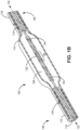
- FIGS. 1A-B illustrate cross sectional views of an automotive cable splicing device 100.
- the automotive cable splicing device 100 includes a core connector terminal 102, a tubular insulation member 108, and an outer sheath 110 including a conductive layer 112.
- a coaxial cable 106 includes a core 104, a dielectric layer 114, an outer shield conductor 116, and an outer insulation layer 118.
- the coaxial cable 106 extends along a longitudinal axis 130 (as illustrated in FIG. 1B ), however, the coaxial cable 106 is flexible to bend or deflect away from the longitudinal axis 130 illustrated in FIG. 1B .
- the coaxial cable 106 is spliced together, i.e., a first coaxial cable 106a is connected to (or joined with) a second coaxial cable 106b, which together form the coaxial cable 106.
- the first end 106a of the coaxial cable 106 may be referred to hereinafter as the first coaxial cable and the second end 106b of the coaxial cable 106 may be referred to hereinafter as the second coaxial cable.
- the core 104, the dielectric layer 114, the outer shield conductor 116, and the outer insulation layer 118 may be identical between the first coaxial cable 106a and the second coaxial cable 106b (e.g., formed of the same materials and dimensions).
- the core connector terminal 102 includes a first connection member 124a, a second connection member 124b, and a conductive spacing member 120 therebetween (the first connection member 124a and the second connection member 124b may also be referred to as attachment members).
- the first connection member 124a receives the core 104 of the first coaxial cable 106a and the second connection member 124b receives the core 104 of the second coaxial cable 106b.
- the first connection member 124a and the second connection member 124b are tubular members, i.e., formed as a substantially cylindrical shape to receive the substantially cylindrical core 104 therein.
- the first connection member 124a and the second connection member 124b are crimped onto the core 104, according to some embodiments.
- the core connector terminal 102 includes a conductive material and a conductive path to electrically connect the core 104 of the first coaxial cable 106a and the core 104 of the second coaxial cable 106b.
- the conductive spacing member 120 includes a first stop surface 122a and a second stop surface 122b.
- the first stop surface 122a engages the core 102 of the first coaxial cable 106a to act as a stopping member, i.e., preventing further insertion of the core within the core connector terminal 102.
- the second stop surface 122b engages the core 102 of the second coaxial cable 106b to act as a stopping member.
- the conductive spacing member 120 may be formed by crimping a portion of the core connector terminal 102, or in other embodiments, the conductive spacing member 120 may be a pre-formed structural element.
- the core connector terminal 102 is a hollow, tubular member.
- the core connector terminal 102 is a multi-winged conductive element that is crimped to form tubular features to receive the core 102 (see e.g., FIGS. 2-4B ).
- the first stop surface 122a and the second stop surface 122b of the conductive spacing member 120 are positioned to create a first gap distance 126a between the first connection member 124a of the core connector terminal 102 and the dielectric layer 114 of the first coaxial cable 106a.
- a second gap distance 126b is created between the second connection member 124b of the core connector terminal 102 and the dielectric layer 114 of the second coaxial cable 106b by the position of the second stop surface 122b.
- the tubular insulation member 108 is sized to fill the first gap distance 126a and the second gap distance 126b.
- the tubular insulation member 108 includes a dielectric material having a substantially similar dielectric constant to the dielectric layer 114.
- a first distal end of the tubular insulation member 108 contacts the dielectric layer 114 of the first coaxial cable 106a and a second distal end of the tubular insulation member 108 contacts the dielectric layer 114 of the second coaxial cable 106b.
- the two main parameters that affect the characteristic impedance are the ratio ( b / a ) and the dielectric constant ⁇ r of the dielectric material.
- the core 104 has a first diameter d 1
- the core connector terminal 102 has a second diameter d 2
- the dielectric layer 114 has a third diameter d 3
- the tubular insulation member 108 has a fourth diameter d 4 .
- the second diameter d 2 of the core connector terminal 102 is greater than the first diameter d 1 of the core 104 because the core connector terminal 102 is sized to at least partially receive the core 104.
- the third diameter d 3 of the dielectric layer 114 to the first diameter d 1 of the core 104 is characterized as a first dielectric to conductor ratio (i.e., d 3 /d 1 is the first dielectric to conductor ratio).
- the fourth diameter d 4 of the tubular insulation member 108 to the second diameter d 2 of the core connector terminal 102 is characterized as a second dielectric to conductor ratio (i.e., d 4 /d 2 is the second dielectric to conductor ratio).
- the dielectric to conductor ratio of the entire coaxial cable 106 and the coaxial cable splicing device 100 may be approximately constant at all locations (e.g., at all cross sections orthogonal to the longitudinal axis 130 of the coaxial cable 106, the dielectric to conductor ratio is approximately d 3 /d 1 ).
- the dielectric to conductor ratio affects the characteristic impedance of the coaxial cable 106, and therefore, the geometric parameters of the dielectric diameter and conductor diameter are scaled together to maintain a constant characteristic impedance. If for example, the characteristic impedance changes throughout the length of a coaxial cable, signal reflection, signal interference, and signal noise would be generated by the changing characteristic impedance. Therefore, it may be beneficial to maintain the same dielectric to conductor ratio throughout the coaxial cable 106 and the coaxial cable splicing device 100.
- a first dielectric constant of the dielectric layer 114 and a dielectric constant of the tubular insulation member 108 are not identical.
- the dielectric to conductor ratio e.g., b / a
- the characteristic impedance can be held approximately constant by selecting the first dielectric constant and/or the second dielectric constant to counteract the inconsistent dielectric to conductor ratio.
- the two variables that affect the characteristic impedance of the coaxial cable are (1) the dielectric to conductor ratio ( b / a ), and (2) the dielectric constant ( ⁇ r ). If one variable changes (e.g., if the dielectric to conductor ratio changes within the coaxial splicing device), the other variable may be selectively altered to keep the characteristic impedance ( Z 0 ) constant.
- the conductive layer 112 of the outer sheath 110 is positioned on an inner surface of the outer sheath 110.
- the conductive layer 112 contacts the outer shield conductor 116 (e.g., conductive braid layer) of the coaxial cable 106.
- the conductive layer 112 electrically couples the outer shield conductor 116 of the first coaxial cable 106a to the outer shield conductor 116 of the second coaxial cable 106b. Electrically coupling the outer shield conductor 116 of the first coaxial cable 106a to the outer shield conductor 116 of the second coaxial cable 106b provides a continuous outer shield layer to prevent signal interference.
- the outer sheath 110 includes a compressive outer layer 132.
- the compressive outer layer 132 provides a tension and/or compressive force upon the conductive layer 112 to urge the conductive layer 112 radially inward toward the longitudinal axis 130.
- the compressive outer layer 132 reinforces the contact between the outer shield conductor 116 and the conductive layer 112 of the outer sheath 110 to ensure the electric connection is maintained through cable bend or deflection.
- the compressive outer layer 132 is a heat shrink element. The compressive outer layer 132 may provide a water-tight barrier over the coaxial cable splicing device 100.
- FIG. 2 illustrates an exploded isometric view of a tubular insulation member 208 and a core connector terminal 202 aligned with the coaxial cable 106, according to some embodiments.
- the coaxial cable 106 is split and stripped into the first coaxial cable 106a and the second coaxial cable 106b, each including the core 104, the dielectric layer 114 surrounding the core 104, the outer shield conductor 116 surrounding the dielectric layer 114, and the outer insulation layer 118 surrounding the outer shield conductor 116.
- the core connector terminal 202 includes a conductive spacing member 220, a first attachment member 224a, and a second attachment member 224b (the first attachment member 224a and the second attachment member 224b may also be referred to as connection members).
- the first attachment member 224a electrically couples to the core 104 of the first coaxial cable 106a and the second attachment member 224b electrically couples to the core 104 of the second coaxial cable 106b.
- the conductive spacing member 220 is positioned in between the first attachment member 224a and the second attachment member 224b and includes stop members that define the length or extent of the core 104 received by the core connector terminal 202. The embodiment illustrated in FIG.
- FIGS. 3A-C show the first attachment member 224a and the second attachment member 224b in a crimped state (i.e., the crimp wings illustrated in FIGS. 3A-C have been crimped).
- the crimp wings of the first attachment member 224a and the second attachment member 224b are not crimped until the core 104 is inserted between the wings (see e.g., FIGS. 3A-4B ).
- the tubular insulation member 208 includes a hinge 234, a first shell 236, and a second shell 238.
- the hinge 234 couples the first shell 236 to the second shell 238.
- the hinge 234 pivots/actuates to allow the first shell 236 to swing away from and/or toward the second shell 238.
- the hinge 234 actuates to allow the first shell 236 to swing away from the second shell 238.
- the core connector terminal 202 and/or the coaxial cable 106 are received within the tubular insulation member 208 while the first shell 236 is positioned away from the second shell 238 (i.e., the tubular insulation member 208 is in an open state).
- the tubular insulation member 208 may be closed via actuation of the hinge 234 urging the first shell 236 toward the second shell 238.
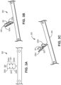
- FIG. 3A illustrates a top view of a core connector terminal 202 in an uncrimped state, according to some embodiments.
- the core connector terminal 202 in the uncrimped state may be formed from a flat sheet of conductive material.
- the core connector terminal 202 may include first deformable wings 225a, second deformable wings 225b, and intermediate deformable wings 221 positioned therebetween.
- the first deformable wings 225a form the first attachment member 224a
- the second deformable wings 225b form the second attachment member 224b
- the intermediate deformable wings 221 form the conductive spacing member 220, according to some embodiments.
- the crimp wings 221, 225a, 225b have the same geometry (dimensions and shape).
- the crimp wings 221, 225a, 225b have different geometries.
- the core connector terminal 202 includes a base section 240 wherein the wings 221, 225a, 225b are deformed around the base section 240.
- each of the first deformable wings 225a, the second deformable wings 225b, and the intermediate deformable wings 221 include at least one wing on each side of the base section 240.
- FIG. 3B illustrates the wings 221, 225a, 225b formed upward relative to the base section 240.
- FIG. 3C illustrates an isometric view of a partially crimped core connector terminal 202, according to some embodiments.
- the intermediate deformable wings 221 are crimped (i.e., folded over toward the base section 240) to form the conductive spacing member 220.
- the first deformable wings 225a and the second deformable wings 225b remain formed upward prior to contact with the core 104 of the coaxial cable 106.
- an excess metal strip 240 may assist positioning and orienting the core connector terminal 202 relative to the coaxial cable 106.
- the core connector terminal 202 includes any and/or all features of the core connector terminal 102 described above, and vice-versa.
- FIG. 4A illustrates the first coaxial cable 106a aligned with the partially crimped core connector terminal 202 shown in FIG. 3C , according to some embodiments.
- the core 104 of the first coaxial cable 106a is partially received between the pair of first deformable wings 225a.
- the core 104 is aligned with the base section 240.
- a distal tip of the core 104 abuts the conductive spacing member 220. Once the distal tip of the core 104 contacts the conductive spacing member 220, the pair of first deformable wings 225a is crimped to the core via deforming each of the first deformable wings 225a toward the core 104.
- FIG. 4B shows the first deformable wings 225a crimped to the core 104 to form the first attachment member 224a.
- the first attachment member 224a is a tubular member which at least partially receives the core 104 therein.
- the core 104 of the first coaxial cable 106a abuts the first stop surface 222a of the conductive spacing member 220.
- the first stop surface 222a of the conductive spacing member 220 thereby controls a distance 242 between the dielectric layer 114 of the first coaxial cable 106a and the distal end of the core 104 of the first coaxial cable 106a.
- the first stop surface 222a of the conductive spacing member 220 controls a gap distance 226 between the dielectric layer 114 of the first coaxial cable 106a and the first attachment member 224a of the core connector terminal 202.
- the core 104 of the second coaxial cable (not shown here) may contact a second stop surface 222b and the pair of second deformable wings 225b may be crimped to the core 104.
- the second stop surface 222b controls a distance (not shown) between the dielectric layer 114 of the second coaxial cable and the distal end of the core 104 of the second coaxial cable and controls a gap distance (not shown) between the dielectric layer 114 of the second coaxial cable and the second attachment member 224b.
- FIG. 5 illustrates an isometric view of the coaxial cable splicing device 200, according to some embodiments.
- the first coaxial cable 106a and the second coaxial cable 106b each include the dielectric layer 114 surrounded by the outer shield conductor 116 and the outer insulation layer 118 surrounding the outer shield conductor 116.
- the automotive coaxial cable splicing device 200 includes the tubular insulation member 208 which contacts the dielectric layer 114 of both the first coaxial cable 106a and the second coaxial cable 106b.
- the automotive coaxial cable splicing device 200 includes an outer sheath (not shown) wrapped around the tubular insulation member 208.
- the outer sheath includes a conductive layer (e.g., a copper tape wound around the longitudinal axis of the tubular insulation member 208 or a tubular conductive braid inserted/slid over the tubular insulation member 208) which contacts the outer shield conductor of both the first coaxial cable 106a and the second coaxial cable 106b.
- the outer sheath includes a heat shrink wrap with a conductive inner lining.
- FIG. 6 illustrates an isometric view of a tubular insulation member 308 in an open state, according to some embodiments.
- the tubular insulation member 308 includes a first shell 336, a second shell 338, and a hinge 334 pivotally coupling the first shell 336 to the second shell 338.
- the tubular insulation member 308 includes a locking detent 346 and a locking recess 348 to receive the locking detent 346, according to some embodiments.
- the first shell 336 and the second shell 338 include a diameter 360 and an aperture having an aperture diameter 358.
- the first shell 336 includes a first cavity 344a and the second shell includes a second cavity 344b (together forming a tubular cavity 344a, 344b in the tubular insulation member 308). Both of the first cavity 344a and the second cavity 334b include a longitudinal length 354 and a cavity diameter 356.
- the tubular insulation member 308 includes a first distal end 350 and a second distal end 352. In some embodiments, the first distal end 350 is separated from the cavity 344a, 344b by a gap filling cap 326a, and the second distal end 352 is separated from the cavity 344a, 344b by a gap filling cap 326b.
- the gap filling caps 326a, 326b are formed of a dielectric material. The gap filling caps 326a, 326b space the core connector terminal 102, 202 from the outer shield conductor 116, and thus, may be referred to as first and second dielectric spacing members, respectively.
- the cavity 344a, 344b is sized to receive the core connector terminal 102, 202 described above in FIGS. 1A-5 .
- the cavity diameter 356 is approximately equal to the diameter of the core connector terminal 102, 202.
- the cavity 344a, 344b may include features to mate with and/or align with features of the core connector terminal 102, 202.
- the cavity 344a, 344b may include ridges or detents that fill spaces between the first attachment member 224b and the conductive spacing member 220 and/or fill spaces between the second attachment member 224b and the conductive spacing member 220.
- Such configuration provides proper positioning/alignment of the core connector terminal 102, 202 within the tubular insulation member 208 and/or reduces the size/quality of air gaps between the core connector terminal 102, 202 and the tubular insulation member 208.
- the longitudinal length 354 of the cavity 344a, 344b is approximately equal to the length of the core connector terminal 102, 202.
- the tubular insulation member 308 includes gap filling caps 326a, 326b at the first and second distal ends 350, 352.
- the gap filling end caps 326a, 326b fill the gap distance 226 (see FIG. 4B ) between the dielectric layer 114 of the coaxial cable 106 and the attachment member 224a, 224b of the core connector terminal 102, 202.
- the gap filling end caps 326a, 326b include an aperture with the aperture diameter 358 approximately equal to the diameter of the core 104.
- the hinge 334 pivotally connects the first shell 336 and the second shell 338.
- FIG. 6 illustrates the tubular insulation member in an open state, i.e., the first shell 336 and the second shell 338 are pivoted away from each other to allow components (e.g., the core connector terminal 102, 202) to be positioned between the first shell 336 and the second shell 338.
- the first shell 336 and the second shell 338 can be urged toward each other via actuation of the hinge 334.
- the locking detent 346 is received in the locking cavity 348 and secures the first shell 336 and the second shell 338 together in a closed state.
- the tubular insulation member 308 includes any and/or all features of the tubular insulation member 108 and 208 described above, and vice-versa.
- FIG. 7 illustrates an exemplary graph 700 of splice shielding performance, according to some embodiments.
- the graph 700 includes electromagnetic interference (EMI) shielding measurements 702 of attenuation (a/dB) versus frequency (MHz).
- EMI electromagnetic interference
- the graph includes a USCAR49 threshold 704.
- USCAR49 is a performance specification for automotive coaxial cables.
- the EMI shielding measurements 702 of the automotive coaxial cable splicing device 100, 200 passes the USCAR49 performance specification.
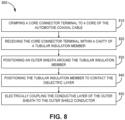
- FIG. 8 illustrates a flow chart of a method 800 for splicing an automotive coaxial cable, according to some embodiments.
- the method 800 includes step 810, crimping a core connector terminal 102, 202 to a core 104 of the automotive coaxial cable 106.
- the method 800 may include stripping the coaxial cable 106 to predetermined lengths, i.e., each layer of the coaxial cable 106 may be stripped to a desired length.
- a stripping tool or stripping fixture is used to create the desired strip lengths at each layer.
- the core 104 of the first coaxial cable 106a is positioned within the first pair of wings 225a and/or the first attachment member 224a and the core 104 of the second coaxial cable 106b is positioned within the second pair of wings 225b and/or the second attachment member 224b.
- the core 104 of the first coaxial cable 106a contacts or abuts the first stop surface 222a and the core 104 of the second coaxial cable 106b contacts or abuts the second stop surface 222b prior to crimping, according to some embodiment.
- step 820 the core connector terminal 102, 202 is received within a cavity 344a, 344b of a tubular insulation member 108, 208, 308.
- step 820 may include providing the tubular insulation member 108, 208, 308 in an open state and aligning the core connector terminal 102, 202 with the cavity 344a, 344b.
- the tubular insulation member 108, 208, 308 can be closed via actuation of the hinge 334 and/or by urging the first shell 336 toward the second shell 338.
- an outer sheath 110 is positioned around the tubular insulation member 108, 208, 308.
- the step 830 may include providing the outer sheath 110 with a conductive layer 112 (e.g., copper tape and/or conductive braid).
- the conductive layer 112 is positioned to contact the outer shield conductor 116 of the first coaxial cable 106a and the second coaxial cable 106b.
- the outer sheath 110 includes a heat shrink tube. The heat shrink tube is positioned on one of the first coaxial cable 106a or the second coaxial cable 106b prior to step 810.
- the heat shrink tube may be moved (i.e., slid) from one of the first coaxial cable 106a or the second coaxial cable 106b to a position overlapping the tubular insulation member 108, 208, 308.
- the heat shrink tube may include the conductive layer 112.
- the conductive layer 112 may be a copper tape (or other conductive tape) wound around the longitudinal axis 130 of the coaxial cable 106.
- the tubular insulation member 108, 208, 308 is positioned to contact the dielectric layer 114 of the coaxial cable 106.
- the first and second distal ends 350, 352 of the tubular insulation member 108, 208, 308 may contact the dielectric layer 114 of the first coaxial cable 106a and the second coaxial cable 106b.
- the conductive layer 112 of the outer sheath 110 is electrically coupled to the outer shield conductor 116.
- the conductive layer 112 is positioned to contact the outer shield conductor 116 of the first coaxial cable 106a and the second coaxial cable 106b.
- the step 810, the step 820, and the step 830 occur sequentially. For example, first the core connector terminal 102, 202 is crimped to the core 104, second the core connector terminal 102, 202 is received within the cavity 344a, 344b of the tubular insulation member 108, 208, 308, and third the outer sheath 110 is positioned around the tubular insulation member 108, 208, 308.
- the above sequence is beneficial because an operator may check the connection status of the core connector terminal 102, 202 to the core 104 prior to enclosing the connection.
- a device for splicing a coaxial cable includes a conductive core, a dielectric layer, and an outer sheath conductor.
- the system includes core connector terminal including a first connection member electrically connectable to a first end of the conductive core of the coaxial cable.
- a second connection member is electrically connectable to a second end of the conductive core of the coaxial cable.
- a conductive spacing member is positioned between the first connection member and the second connection member.
- a tubular insulation member includes a first shell, a second shell, a hinge connecting the first shell and the second shell, a first distal end having a first width, a second distal end having a second width, and a cavity formed between the first shell and the second shell.
- the cavity is positioned between the first distal end and the second distal end.
- the core connector terminal is receivable within the cavity of the tubular insulation member.
- the conductive spacing member includes a first stop surface to engage the first end of the conductive core.
- the first stop surface is positioned to generate a first gap between the first connection member and the dielectric layer of the coaxial cable.
- the first width of the first distal end is approximately equal to the first gap to fit between the first connection member and the dielectric layer of the coaxial cable.
- the system further comprises an outer sheath positioned radially outward of the tubular insulation member.
- the outer sheath includes a conductive layer electrically connectable to the outer sheath conductor of the coaxial cable.
- a first dielectric constant of the dielectric layer is approximately equal to a second dielectric constant of the tubular insulation member.
- the coaxial cable includes a first dielectric ratio of a first diameter of the dielectric layer compared to a second diameter of the conductive core.
- the coaxial cable includes a second dielectric ratio of a third diameter of the tubular insulation member compared to a fourth diameter of the core connector terminal. The second dielectric ratio is approximately equal to the first dielectric ratio.
Landscapes
- Engineering & Computer Science (AREA)
- Manufacturing & Machinery (AREA)
- Coupling Device And Connection With Printed Circuit (AREA)
Abstract

Description
- The present disclosure relates generally to coaxial cable splicing devices, systems, and methods for automotive coaxial cables.
- In general, a coaxial cable comprises a core conductor, a dielectric layer surrounding the core conductor, an outer conductive sheath (e.g., a conductive braid) surrounding the dielectric layer, and an outer insulation layer surrounding the outer conductive sheath. Coaxial cables are often used in automotive applications to transfer signals between various automotive sensors, vehicle controls, and/or vehicle systems. Because the outer conductive sheath contains the electric field and magnetic field of the signal (i.e., current) flowing through the core conductor, coaxial cables provide good performance, protecting the signal from outside interference. As a result, a large number of coaxial cables can be positioned near each other without interference from adjacent coaxial cables degrading the signals. In general, damaged automotive coaxial cables are generally removed and replaced with an entirely new coaxial cable. It would be beneficial to develop a device and/or method for repairing damaged coaxial cables without degrading performance of the cable.
- According to some embodiments, an automotive coaxial cable splicing device includes a core connector terminal and a tubular insulation member. The core connector terminal includes a first connection member configured to receive a first core of a first coaxial cable and a second connection member configured to receive a second core of a second coaxial cable therein. The conductive spacing member includes a first stop surface to engage the first core and a second stop surface to engage the second core. The tubular insulation member includes a cavity configured to receive the core connector terminal, the first core of the first coaxial cable, and the second core of the second coaxial cable therein.
- According to some embodiments, a method for splicing an automotive coaxial cable includes crimping a core connector terminal to a first core and a second core of the automotive coaxial cable. The core connector terminal includes a first connection member configured to receive the first core and a second connection member configured to receive the second core. A conductive spacing member is positioned between the first connection member and the second connection member. The method includes receiving the core connector terminal within a cavity of a tubular insulation member. An outer sheath is positioned around the tubular insulation member. The outer sheath includes a conductive layer.
- According to some embodiments, a system for splicing an automotive coaxial cable including a conductive core, a dielectric layer, and an outer sheath conductor. The system includes a core connector terminal including a first connection member electrically connectable to a first end of the conductive core of the automotive coaxial cable. A second connection member is electrically connectable to a second end of the conductive core of the automotive coaxial cable. A conductive spacing member is positioned between the first connection member and the second connection member. The system includes a tubular insulation member, The tubular insulation member includes a first shell, a second shell, a hinge connecting the first shell and the second shell, a first distal end having a first width, and a second distal end having a second width. A cavity is formed between the first shell and the second shell. The cavity is positioned between the first distal end and the second distal end. The core connector terminal is receivable within the cavity of the tubular insulation member.
- These and other examples and features of the present devices, systems, and methods will be set forth, at least in part, in the following Detailed Description. This Overview is intended to provide non-limiting examples of the present subject matter-it is not intended to provide an exclusive or exhaustive explanation. The Detailed Description below is included to provide further information about the present devices, systems, and methods.
- This written disclosure describes illustrative embodiments that are non-limiting and non-exhaustive. Reference is made to illustrative embodiments that are depicted in the figures, in which:
-
FIG. 1A illustrates a cross sectional side view of an automotive cable splicing device, according to some embodiments. -
FIG. 1B illustrates a cross sectional isometric view of an automotive cable splicing device, according to some embodiments. -
FIG. 2 illustrates an exploded isometric view of a core connector terminal and a tubular insertion member aligned with a longitudinal axis of a coaxial cable, according to some embodiments. -
FIG. 3A illustrates a top view of an uncrimped core connector terminal, according to some embodiments. -
FIG. 3B illustrates an isometric view of a partially crimped core connector terminal, according to some embodiments. -
FIG. 3C illustrates an isometric view of a partially crimped core connector terminal, according to some embodiments. -
FIG. 4A illustrates an isometric view of a partially crimped core connector terminal aligned with a coaxial cable, according to some embodiments. -
FIG. 4B illustrates an isometric view of a partially crimped core connector terminal with a first tubular member crimped to a core of a coaxial cable, according to some embodiments. -
FIG. 5 illustrates an isometric view of a tubular insulation member secured to a coaxial cable, according to some embodiments. -
FIG. 6 illustrates an isometric view of a tubular insulation member, according to some embodiments. -
FIG. 7 illustrates a graph of coaxial splice shielding signal attenuation, according to some embodiments. -
FIG. 8 illustrates a flow chart of a method for splicing an automotive coaxial cable, according to some embodiments. - According to some embodiments, this disclosure relates to devices, systems, and methods for splicing automotive coaxial cables. In some embodiments, an automotive coaxial cable splicing device includes a core connector terminal and a tubular insulation member. An automotive coaxial cable includes a core, a dielectric layer surrounding the core, an outer conductive sheath surrounding the dielectric layer, and an insulation layer surrounding the outer conductive sheath. The core connector terminal receives a first core (associated with a first coaxial cable) and a second core (associated with a second coaxial cable). The core connector terminal is electrically conductive to electrically couple the first core the second core. The core connector terminal is received within the tubular insulation member. In some embodiments, the tubular insulation member is received within an outer sheath including a conductive layer.
- In some embodiments, the core includes a core diameter and the dielectric layer includes a first dielectric diameter. The core connector terminal includes a terminal diameter, and the dielectric tubular insulation member includes a second dielectric diameter. The terminal diameter is greater than the core diameter. The ratio of the core diameter to the first dielectric diameter (i.e., the coaxial cable ratio) may be approximately equal to the ratio of the terminal diameter to the second dielectric diameter (i.e., the slicing device ratio). The conductor to dielectric ratio affects the characteristic impedance of the coaxial cable, and therefore, in some embodiments it is beneficial to maintain a constant conductor to dielectric ratio throughout the coaxial cable and spliced section. Changes to the conductor to dielectric ratio results in unwanted impedances which degrade signal transmission (e.g., cause signal reflection, interference, or other signal noise). In some embodiments, a dielectric constant of the dielectric tubular insulation member is different from the dielectric constant of the dielectric layer. In such cases, the conductor to dielectric ratio is configured to keep the characteristic impedance constant.
- In some embodiments, the core connector terminal includes conductive spacing member including a first stop surface and a second stop surface. The first stop surface engages the end of the first core and the second stop surface engages the end of the second core. The conductive spacing member ensures a predetermined length of the core is received within the core connector terminal, and thus, a gap distance between the dielectric layer of the coaxial cable and the core connector terminal is controlled. Controlling the gap distance between the dielectric layer of the coaxial cable and the core terminal is important, as the tubular insulation member may be shaped to precisely fill the gap distance therebetween. If the tubular insulation does not precisely fill the gap, air pockets may be present within the tubular insulation member (air having a different dielectric constant/relative permittivity than the dielectric material) which may result in unwanted impedances which degrade signal transmission (e.g., cause signal reflection, interference, or other signal noise). Thus, it is beneficial to form a precise fit between the tubular insulation member, the core connector terminal, and the coaxial cable.
-
FIGS. 1A-B illustrate cross sectional views of an automotivecable splicing device 100. In some embodiments, the automotivecable splicing device 100 includes acore connector terminal 102, atubular insulation member 108, and anouter sheath 110 including aconductive layer 112. In some embodiments, acoaxial cable 106 includes acore 104, adielectric layer 114, anouter shield conductor 116, and anouter insulation layer 118. Thecoaxial cable 106 extends along a longitudinal axis 130 (as illustrated inFIG. 1B ), however, thecoaxial cable 106 is flexible to bend or deflect away from thelongitudinal axis 130 illustrated inFIG. 1B . Thecoaxial cable 106 is spliced together, i.e., a firstcoaxial cable 106a is connected to (or joined with) a secondcoaxial cable 106b, which together form thecoaxial cable 106. Thefirst end 106a of thecoaxial cable 106 may be referred to hereinafter as the first coaxial cable and thesecond end 106b of thecoaxial cable 106 may be referred to hereinafter as the second coaxial cable. In some embodiments, thecore 104, thedielectric layer 114, theouter shield conductor 116, and theouter insulation layer 118 may be identical between the firstcoaxial cable 106a and the secondcoaxial cable 106b (e.g., formed of the same materials and dimensions). - In some embodiments, the
core connector terminal 102 includes afirst connection member 124a, asecond connection member 124b, and aconductive spacing member 120 therebetween (thefirst connection member 124a and thesecond connection member 124b may also be referred to as attachment members). Thefirst connection member 124a receives thecore 104 of the firstcoaxial cable 106a and thesecond connection member 124b receives thecore 104 of the secondcoaxial cable 106b. In some embodiments, thefirst connection member 124a and thesecond connection member 124b are tubular members, i.e., formed as a substantially cylindrical shape to receive the substantiallycylindrical core 104 therein. Thefirst connection member 124a and thesecond connection member 124b are crimped onto thecore 104, according to some embodiments. Thecore connector terminal 102 includes a conductive material and a conductive path to electrically connect thecore 104 of the firstcoaxial cable 106a and thecore 104 of the secondcoaxial cable 106b. In some embodiments, theconductive spacing member 120 includes afirst stop surface 122a and asecond stop surface 122b. Thefirst stop surface 122a engages thecore 102 of the firstcoaxial cable 106a to act as a stopping member, i.e., preventing further insertion of the core within thecore connector terminal 102. Thesecond stop surface 122b engages thecore 102 of the secondcoaxial cable 106b to act as a stopping member. Theconductive spacing member 120 may be formed by crimping a portion of thecore connector terminal 102, or in other embodiments, theconductive spacing member 120 may be a pre-formed structural element. In some embodiments, thecore connector terminal 102 is a hollow, tubular member. In other embodiments, thecore connector terminal 102 is a multi-winged conductive element that is crimped to form tubular features to receive the core 102 (see e.g.,FIGS. 2-4B ). - In some embodiments, the
first stop surface 122a and thesecond stop surface 122b of theconductive spacing member 120 are positioned to create afirst gap distance 126a between thefirst connection member 124a of thecore connector terminal 102 and thedielectric layer 114 of the firstcoaxial cable 106a. Asecond gap distance 126b is created between thesecond connection member 124b of thecore connector terminal 102 and thedielectric layer 114 of the secondcoaxial cable 106b by the position of thesecond stop surface 122b. Thetubular insulation member 108 is sized to fill thefirst gap distance 126a and thesecond gap distance 126b. Controlling thefirst gap distance 126a and thesecond gap distance 126b is beneficial, as thetubular insulation member 108 is sized to fill thefirst gap distance 126a and thesecond gap distance 126b and thereby remove air gaps within the coaxialcable splicing device 100. In some embodiments, thetubular insulation member 108 includes a dielectric material having a substantially similar dielectric constant to thedielectric layer 114. In some embodiments, a first distal end of thetubular insulation member 108 contacts thedielectric layer 114 of the firstcoaxial cable 106a and a second distal end of thetubular insulation member 108 contacts thedielectric layer 114 of the secondcoaxial cable 106b. - In some embodiments, a characteristic impedance of the
coaxial cable 106 is expressed as:
- In some embodiments, the
core 104 has a first diameter d1, thecore connector terminal 102 has a second diameter d2, thedielectric layer 114 has a third diameter d3, and thetubular insulation member 108 has a fourth diameter d4. The second diameter d2 of thecore connector terminal 102 is greater than the first diameter d1 of thecore 104 because thecore connector terminal 102 is sized to at least partially receive thecore 104. The third diameter d3 of thedielectric layer 114 to the first diameter d1 of thecore 104 is characterized as a first dielectric to conductor ratio (i.e., d3/d1 is the first dielectric to conductor ratio). The fourth diameter d4 of thetubular insulation member 108 to the second diameter d2 of thecore connector terminal 102 is characterized as a second dielectric to conductor ratio (i.e., d4/d2 is the second dielectric to conductor ratio). In some embodiments, the first dielectric to conductor ratio is approximately equal to the second dielectric to conductor ration (d3/d1 = d4/d2). In some embodiments, the dielectric to conductor ratio of the entirecoaxial cable 106 and the coaxialcable splicing device 100 may be approximately constant at all locations (e.g., at all cross sections orthogonal to thelongitudinal axis 130 of thecoaxial cable 106, the dielectric to conductor ratio is approximately d3/d1). - The dielectric to conductor ratio affects the characteristic impedance of the
coaxial cable 106, and therefore, the geometric parameters of the dielectric diameter and conductor diameter are scaled together to maintain a constant characteristic impedance. If for example, the characteristic impedance changes throughout the length of a coaxial cable, signal reflection, signal interference, and signal noise would be generated by the changing characteristic impedance. Therefore, it may be beneficial to maintain the same dielectric to conductor ratio throughout thecoaxial cable 106 and the coaxialcable splicing device 100. - In some embodiments, a first dielectric constant of the
dielectric layer 114 and a dielectric constant of thetubular insulation member 108 are not identical. For example, if the dielectric to conductor ratio (e.g., b/a) is not constant throughout thecoaxial cable 106 and the coaxialcable splicing device 100, the characteristic impedance can be held approximately constant by selecting the first dielectric constant and/or the second dielectric constant to counteract the inconsistent dielectric to conductor ratio. In other words, the two variables that affect the characteristic impedance of the coaxial cable are (1) the dielectric to conductor ratio (b/a), and (2) the dielectric constant (εr ). If one variable changes (e.g., if the dielectric to conductor ratio changes within the coaxial splicing device), the other variable may be selectively altered to keep the characteristic impedance (Z0 ) constant. - In some embodiments, the
conductive layer 112 of theouter sheath 110 is positioned on an inner surface of theouter sheath 110. Theconductive layer 112 contacts the outer shield conductor 116 (e.g., conductive braid layer) of thecoaxial cable 106. Theconductive layer 112 electrically couples theouter shield conductor 116 of the firstcoaxial cable 106a to theouter shield conductor 116 of the secondcoaxial cable 106b. Electrically coupling theouter shield conductor 116 of the firstcoaxial cable 106a to theouter shield conductor 116 of the secondcoaxial cable 106b provides a continuous outer shield layer to prevent signal interference. - In some embodiments, the
outer sheath 110 includes a compressiveouter layer 132. The compressiveouter layer 132 provides a tension and/or compressive force upon theconductive layer 112 to urge theconductive layer 112 radially inward toward thelongitudinal axis 130. In some embodiments, the compressiveouter layer 132 reinforces the contact between theouter shield conductor 116 and theconductive layer 112 of theouter sheath 110 to ensure the electric connection is maintained through cable bend or deflection. In some embodiments, the compressiveouter layer 132 is a heat shrink element. The compressiveouter layer 132 may provide a water-tight barrier over the coaxialcable splicing device 100. -
FIG. 2 illustrates an exploded isometric view of atubular insulation member 208 and acore connector terminal 202 aligned with thecoaxial cable 106, according to some embodiments. Thecoaxial cable 106 is split and stripped into the firstcoaxial cable 106a and the secondcoaxial cable 106b, each including thecore 104, thedielectric layer 114 surrounding thecore 104, theouter shield conductor 116 surrounding thedielectric layer 114, and theouter insulation layer 118 surrounding theouter shield conductor 116. - In some embodiments, the
core connector terminal 202 includes aconductive spacing member 220, afirst attachment member 224a, and asecond attachment member 224b (thefirst attachment member 224a and thesecond attachment member 224b may also be referred to as connection members). Thefirst attachment member 224a electrically couples to thecore 104 of the firstcoaxial cable 106a and thesecond attachment member 224b electrically couples to thecore 104 of the secondcoaxial cable 106b. Theconductive spacing member 220 is positioned in between thefirst attachment member 224a and thesecond attachment member 224b and includes stop members that define the length or extent of thecore 104 received by thecore connector terminal 202. The embodiment illustrated inFIG. 2 shows thefirst attachment member 224a and thesecond attachment member 224b in a crimped state (i.e., the crimp wings illustrated inFIGS. 3A-C have been crimped). In some embodiments, the crimp wings of thefirst attachment member 224a and thesecond attachment member 224b are not crimped until thecore 104 is inserted between the wings (see e.g.,FIGS. 3A-4B ). - In some embodiments, the
tubular insulation member 208 includes ahinge 234, afirst shell 236, and asecond shell 238. Thehinge 234 couples thefirst shell 236 to thesecond shell 238. Thehinge 234 pivots/actuates to allow thefirst shell 236 to swing away from and/or toward thesecond shell 238. In some embodiments, thehinge 234 actuates to allow thefirst shell 236 to swing away from thesecond shell 238. Thecore connector terminal 202 and/or thecoaxial cable 106 are received within thetubular insulation member 208 while thefirst shell 236 is positioned away from the second shell 238 (i.e., thetubular insulation member 208 is in an open state). Once thecore connector terminal 202 and/or thecoaxial cable 106 are positioned between thefirst shell 236 and thesecond shell 238, thetubular insulation member 208 may be closed via actuation of thehinge 234 urging thefirst shell 236 toward thesecond shell 238. -
FIG. 3A illustrates a top view of acore connector terminal 202 in an uncrimped state, according to some embodiments. Thecore connector terminal 202 in the uncrimped state may be formed from a flat sheet of conductive material. In some embodiments, thecore connector terminal 202 may include firstdeformable wings 225a, seconddeformable wings 225b, and intermediatedeformable wings 221 positioned therebetween. The firstdeformable wings 225a form thefirst attachment member 224a, the seconddeformable wings 225b form thesecond attachment member 224b, and the intermediatedeformable wings 221 form theconductive spacing member 220, according to some embodiments. In some embodiments, thecrimp wings crimp wings core connector terminal 202 includes abase section 240 wherein thewings base section 240. In some embodiments, each of the firstdeformable wings 225a, the seconddeformable wings 225b, and the intermediatedeformable wings 221 include at least one wing on each side of thebase section 240. For instance,FIG. 3B illustrates thewings base section 240. -
FIG. 3C illustrates an isometric view of a partially crimpedcore connector terminal 202, according to some embodiments. The intermediatedeformable wings 221 are crimped (i.e., folded over toward the base section 240) to form theconductive spacing member 220. The firstdeformable wings 225a and the seconddeformable wings 225b remain formed upward prior to contact with thecore 104 of thecoaxial cable 106. In some embodiments, anexcess metal strip 240 may assist positioning and orienting thecore connector terminal 202 relative to thecoaxial cable 106. In some embodiments, thecore connector terminal 202 includes any and/or all features of thecore connector terminal 102 described above, and vice-versa. -
FIG. 4A illustrates the firstcoaxial cable 106a aligned with the partially crimpedcore connector terminal 202 shown inFIG. 3C , according to some embodiments. Thecore 104 of the firstcoaxial cable 106a is partially received between the pair of firstdeformable wings 225a. Thecore 104 is aligned with thebase section 240. In some embodiments, a distal tip of thecore 104 abuts theconductive spacing member 220. Once the distal tip of the core 104 contacts theconductive spacing member 220, the pair of firstdeformable wings 225a is crimped to the core via deforming each of the firstdeformable wings 225a toward thecore 104. - For instance,
FIG. 4B shows the firstdeformable wings 225a crimped to thecore 104 to form thefirst attachment member 224a. Thefirst attachment member 224a is a tubular member which at least partially receives thecore 104 therein. Thecore 104 of the firstcoaxial cable 106a abuts the first stop surface 222a of theconductive spacing member 220. The first stop surface 222a of theconductive spacing member 220 thereby controls adistance 242 between thedielectric layer 114 of the firstcoaxial cable 106a and the distal end of thecore 104 of the firstcoaxial cable 106a. Likewise, the first stop surface 222a of theconductive spacing member 220 controls agap distance 226 between thedielectric layer 114 of the firstcoaxial cable 106a and thefirst attachment member 224a of thecore connector terminal 202. In some embodiments, thecore 104 of the second coaxial cable (not shown here) may contact asecond stop surface 222b and the pair of seconddeformable wings 225b may be crimped to thecore 104. Thesecond stop surface 222b controls a distance (not shown) between thedielectric layer 114 of the second coaxial cable and the distal end of thecore 104 of the second coaxial cable and controls a gap distance (not shown) between thedielectric layer 114 of the second coaxial cable and thesecond attachment member 224b. -
FIG. 5 illustrates an isometric view of the coaxialcable splicing device 200, according to some embodiments. The firstcoaxial cable 106a and the secondcoaxial cable 106b each include thedielectric layer 114 surrounded by theouter shield conductor 116 and theouter insulation layer 118 surrounding theouter shield conductor 116. In some embodiments, the automotive coaxialcable splicing device 200 includes thetubular insulation member 208 which contacts thedielectric layer 114 of both the firstcoaxial cable 106a and the secondcoaxial cable 106b. In some embodiments, the automotive coaxialcable splicing device 200 includes an outer sheath (not shown) wrapped around thetubular insulation member 208. In one example, the outer sheath includes a conductive layer (e.g., a copper tape wound around the longitudinal axis of thetubular insulation member 208 or a tubular conductive braid inserted/slid over the tubular insulation member 208) which contacts the outer shield conductor of both the firstcoaxial cable 106a and the secondcoaxial cable 106b. In one example, the outer sheath includes a heat shrink wrap with a conductive inner lining. -
FIG. 6 illustrates an isometric view of atubular insulation member 308 in an open state, according to some embodiments. In some embodiments, thetubular insulation member 308 includes afirst shell 336, asecond shell 338, and ahinge 334 pivotally coupling thefirst shell 336 to thesecond shell 338. Thetubular insulation member 308 includes alocking detent 346 and alocking recess 348 to receive thelocking detent 346, according to some embodiments. Thefirst shell 336 and thesecond shell 338 include adiameter 360 and an aperture having anaperture diameter 358. Thefirst shell 336 includes afirst cavity 344a and the second shell includes asecond cavity 344b (together forming atubular cavity first cavity 344a and the second cavity 334b include alongitudinal length 354 and acavity diameter 356. Thetubular insulation member 308 includes a firstdistal end 350 and a seconddistal end 352. In some embodiments, the firstdistal end 350 is separated from thecavity gap filling cap 326a, and the seconddistal end 352 is separated from thecavity gap filling cap 326b. Thegap filling caps gap filling caps core connector terminal outer shield conductor 116, and thus, may be referred to as first and second dielectric spacing members, respectively. - In some embodiments, the
cavity core connector terminal FIGS. 1A-5 . Thecavity diameter 356 is approximately equal to the diameter of thecore connector terminal cavity core connector terminal cavity first attachment member 224b and theconductive spacing member 220 and/or fill spaces between thesecond attachment member 224b and theconductive spacing member 220. Such configuration provides proper positioning/alignment of thecore connector terminal tubular insulation member 208 and/or reduces the size/quality of air gaps between thecore connector terminal tubular insulation member 208. In some embodiments, thelongitudinal length 354 of thecavity core connector terminal - In some embodiments, the
tubular insulation member 308 includesgap filling caps end caps FIG. 4B ) between thedielectric layer 114 of thecoaxial cable 106 and theattachment member core connector terminal end caps aperture diameter 358 approximately equal to the diameter of thecore 104. - In some embodiments, the
hinge 334 pivotally connects thefirst shell 336 and thesecond shell 338.FIG. 6 illustrates the tubular insulation member in an open state, i.e., thefirst shell 336 and thesecond shell 338 are pivoted away from each other to allow components (e.g., thecore connector terminal 102, 202) to be positioned between thefirst shell 336 and thesecond shell 338. Once the desired components are positioned between thefirst shell 336 and thesecond shell 338, thefirst shell 336 and thesecond shell 338 can be urged toward each other via actuation of thehinge 334. In some embodiments, thelocking detent 346 is received in thelocking cavity 348 and secures thefirst shell 336 and thesecond shell 338 together in a closed state. In some embodiments, thetubular insulation member 308 includes any and/or all features of thetubular insulation member -
FIG. 7 illustrates anexemplary graph 700 of splice shielding performance, according to some embodiments. Thegraph 700 includes electromagnetic interference (EMI) shieldingmeasurements 702 of attenuation (a/dB) versus frequency (MHz). The graph includes aUSCAR49 threshold 704. USCAR49 is a performance specification for automotive coaxial cables. FIG. TheEMI shielding measurements 702 of the automotive coaxialcable splicing device -
FIG. 8 illustrates a flow chart of amethod 800 for splicing an automotive coaxial cable, according to some embodiments. Themethod 800 includesstep 810, crimping acore connector terminal core 104 of the automotivecoaxial cable 106. In some embodiments, themethod 800 may include stripping thecoaxial cable 106 to predetermined lengths, i.e., each layer of thecoaxial cable 106 may be stripped to a desired length. In some embodiments, a stripping tool or stripping fixture is used to create the desired strip lengths at each layer. Atstep 810, thecore 104 of the firstcoaxial cable 106a is positioned within the first pair ofwings 225a and/or thefirst attachment member 224a and thecore 104 of the secondcoaxial cable 106b is positioned within the second pair ofwings 225b and/or thesecond attachment member 224b. Thecore 104 of the firstcoaxial cable 106a contacts or abuts the first stop surface 222a and thecore 104 of the secondcoaxial cable 106b contacts or abuts thesecond stop surface 222b prior to crimping, according to some embodiment. - At
step 820, thecore connector terminal cavity tubular insulation member step 820 may include providing thetubular insulation member core connector terminal cavity tubular insulation member hinge 334 and/or by urging thefirst shell 336 toward thesecond shell 338. - At
step 830, anouter sheath 110 is positioned around thetubular insulation member step 830 may include providing theouter sheath 110 with a conductive layer 112 (e.g., copper tape and/or conductive braid). In some embodiments, theconductive layer 112 is positioned to contact theouter shield conductor 116 of the firstcoaxial cable 106a and the secondcoaxial cable 106b. In some embodiments, theouter sheath 110 includes a heat shrink tube. The heat shrink tube is positioned on one of the firstcoaxial cable 106a or the secondcoaxial cable 106b prior to step 810. After thestep 810 and thestep 820, the heat shrink tube may be moved (i.e., slid) from one of the firstcoaxial cable 106a or the secondcoaxial cable 106b to a position overlapping thetubular insulation member conductive layer 112. In other embodiments, theconductive layer 112 may be a copper tape (or other conductive tape) wound around thelongitudinal axis 130 of thecoaxial cable 106. - At
step 840, thetubular insulation member dielectric layer 114 of thecoaxial cable 106. The first and second distal ends 350, 352 of thetubular insulation member dielectric layer 114 of the firstcoaxial cable 106a and the secondcoaxial cable 106b. - At
step 850, theconductive layer 112 of theouter sheath 110 is electrically coupled to theouter shield conductor 116. In some embodiments, theconductive layer 112 is positioned to contact theouter shield conductor 116 of the firstcoaxial cable 106a and the secondcoaxial cable 106b. - In some embodiments, the
step 810, thestep 820, and thestep 830 occur sequentially. For example, first thecore connector terminal core 104, second thecore connector terminal cavity tubular insulation member outer sheath 110 is positioned around thetubular insulation member core connector terminal core 104 prior to enclosing the connection. - In some embodiments, a device for splicing a coaxial cable includes a conductive core, a dielectric layer, and an outer sheath conductor. The system includes core connector terminal including a first connection member electrically connectable to a first end of the conductive core of the coaxial cable. A second connection member is electrically connectable to a second end of the conductive core of the coaxial cable. A conductive spacing member is positioned between the first connection member and the second connection member. A tubular insulation member includes a first shell, a second shell, a hinge connecting the first shell and the second shell, a first distal end having a first width, a second distal end having a second width, and a cavity formed between the first shell and the second shell. The cavity is positioned between the first distal end and the second distal end. The core connector terminal is receivable within the cavity of the tubular insulation member. The conductive spacing member includes a first stop surface to engage the first end of the conductive core. The first stop surface is positioned to generate a first gap between the first connection member and the dielectric layer of the coaxial cable. The first width of the first distal end is approximately equal to the first gap to fit between the first connection member and the dielectric layer of the coaxial cable. In some embodiments, the system further comprises an outer sheath positioned radially outward of the tubular insulation member. The outer sheath includes a conductive layer electrically connectable to the outer sheath conductor of the coaxial cable. In some embodiments, a first dielectric constant of the dielectric layer is approximately equal to a second dielectric constant of the tubular insulation member. The coaxial cable includes a first dielectric ratio of a first diameter of the dielectric layer compared to a second diameter of the conductive core. The coaxial cable includes a second dielectric ratio of a third diameter of the tubular insulation member compared to a fourth diameter of the core connector terminal. The second dielectric ratio is approximately equal to the first dielectric ratio.
- While the invention has been described with reference to an exemplary embodiment(s), it will be understood by those skilled in the art that various changes may be made and equivalents may be substituted for elements thereof without departing from the scope of the invention. In addition, many modifications may be made to adapt a particular situation or material to the teachings of the invention without departing from the essential scope thereof. Therefore, it is intended that the invention not be limited to the particular embodiment(s) disclosed, but that the invention will include all embodiments falling within the scope of the appended claims.
Claims (15)
- A coaxial cable splicing device (100), comprising:a core connector terminal (102, 202) including:a first connection member (124a, 224a) configured to receive a first core (104) of a first coaxial cable (106, 106a) therein,a second connection member (124b, 224b) configured to receive a second core (104) of a second coaxial cable (106, 106b) therein, anda conductive spacing member (120, 220) positioned between the first connection member (124a, 224a) and the second connection member (124b, 224b), the conductive spacing member (120, 220) including a first stop surface (122a, 222a) to engage the first core (104) and a second stop surface (122b, 222b) to engage the second core (104); anda tubular insulation member (108, 208, 308) including a cavity (344a, 344b) configured to receive the core connector terminal (102, 202), the first core (104) of the first coaxial cable (106, 106a), and the second core (104) of the second coaxial cable (106, 106b) therein.
- The coaxial cable splicing device (100) of claim 1, wherein the core connector terminal (102, 202) is a one-piece construction including a first set of crimp wings (225a) crimped around the first core (104) to form the first connection member (124a, 224a) and a second set of crimp wings (225b) crimped around the second core (104) to form the second connection member (124b, 224b).
- The coaxial cable splicing device (100) of claims 1 or 2, further comprising:an outer sheath (110) including a conductive layer (112),wherein the conductive layer (112) of the outer sheath (110) is electrically coupled to a first outer shield conductor (116) of the first coaxial cable (106, 106a) and a second outer shield conductor (116) of the second coaxial cable (106, 106b).
- The coaxial cable splicing device (100) of claim 3, wherein the outer sheath (110) includes a compressive outer layer (132) configured to urge the conductive layer (112) of the outer sheath (110) radially inward toward the first coaxial cable (106, 106a) and the second coaxial cable (106, 106b).
- The coaxial cable splicing device (100) of any of claims 1-4, wherein the first stop surface (122a, 222a) of the conductive spacing member (120, 220) is configured to control a gap distance (126a) between the first connection member (124a, 224a) and a first dielectric layer (114) of the first coaxial cable (106, 106a).
- The coaxial cable splicing device (100) of claim 5, wherein a first distal end (350) of the tubular insulation member (108, 208, 308) contacts the first dielectric layer (114) of the first coaxial cable (106, 106a) and a second distal end (352) of the tubular insulation member (108, 208, 308) contacts a second dielectric layer (114) of the second coaxial cable (106, 106b).
- The coaxial cable splicing device (100) of claim 6, wherein the tubular insulation member (108, 208, 308) includes a first dielectric spacing member (326a) at the first distal end (350), wherein the first dielectric spacing member (326a) is approximately equal length to the first gap distance (126a) between the first connection member (124a, 224a) and the first dielectric layer (114), and wherein the first dielectric spacing member (326a) is configured to be received within the first gap distance (126a) between the first connection member (124a, 224a) and the first dielectric layer (114).
- The coaxial cable splicing device (100) of any of claims 1-7, wherein:a first dielectric constant of the dielectric layer (114) of the first or second coaxial cable (106, 106a, 106b) is approximately equal to a second dielectric constant of the tubular insulation member (108, 208, 308),the first core (104) and the second core (104) have a first outer diameter (d1),the first connection member (124a, 224a) and the second connection member (124b, 224b) have a second outer diameter (d2) greater than the first outer diameter (d1),a first dielectric layer (114) of the first coaxial cable (106, 106a) and a second dielectric layer (114) of the second coaxial cable (106, 106b) have a third outer diameter (d3),the tubular insulation member (108, 208, 308) has a fourth outer diameter (d4) greater than the third outer diameter (d3), andwherein a first ratio of the third outer diameter (d3) to the first outer diameter (d1) is approximately equal to a second ratio of the fourth outer diameter (d4) to the second outer diameter (d2).
- A method (800) for splicing a coaxial cable (106, 106a, 106b), the method comprising:crimping (800) a core connector terminal (102, 202) to a first core (104) and a second core (104) of the coaxial cable (106, 106a, 106b), the core connector terminal (102, 202) including:a first connection member (124a, 224a) configured to receive the first core (104),a second connection member (124b, 224b) configured to receive the second core (104), anda conductive spacing member (120, 220) positioned between the first connection member (124a, 224a) and the second connection member (124b, 224b);receiving (820) the core connector terminal (102, 202) within a cavity (344a, 344b) of a tubular insulation member (108, 208, 308); andpositioning (830) an outer sheath (110) around the tubular insulation member (108, 208, 308), the outer sheath (110) including a conductive layer (112).
- The method (800) of claim 9, where the coaxial cable (106, 106a, 106b) includes:a dielectric layer (114) surrounding the first core (104) and the second core (104),an outer shield conductor (116) surrounding the dielectric layer (114), andan outer insulator (118) surrounding the outer shield conductor (116).
- The method (800) of claim 10 further comprising:positioning (840) the tubular insulation member (108, 208, 308) to contact the dielectric layer (114) of the coaxial cable (106, 106a, 106b); andelectrically coupling (850) the conductive layer (112) of the outer sheath (110) to the outer shield conductor (116) of the coaxial cable (106, 106a, 106b).
- The method (800) of any of claims 9 to 11, wherein the core connector terminal (102, 202) is crimped to the first core (104) and the second core (104) before the core connector terminal (102, 202) is received within the tubular insulation member (108, 208, 308), and wherein the tubular insulation member (108, 208, 308) receives the core connector terminal (102, 202) before the outer sheath (110) is positioned around the tubular insulation member (108, 208, 308).
- The method (800) of any of claims 9 to 12, further comprising:
crimping a flat, three-winged conductive element (202) to form the core connector terminal (202), wherein a center wing (221) is crimped to form the conductive spacing member (220). - The method (800) of any of claims 9 to 13 further comprising:urging a first shell (336) of the tubular insulation member (108, 208, 308) toward a second shell (338) of the tubular insulation member (108, 208, 308) to enclose the core connector terminal (102, 202) therebetween,wherein the first shell (336) and the second shell (338) are connected via a hinge mechanism (334).
- The method (800) of any of claims 9 to 14 further comprising:heating the outer sheath (110) to constrict the outer sheath (110) radially inward toward the coaxial cable (106, 106a, 106b) therein,wherein the outer sheath (110) includes a heat shrink element (132) positioned radially outward from the conductive layer (112),wherein constricting the heat shrink element (132) provides a water-tight seal.
Applications Claiming Priority (2)
| Application Number | Priority Date | Filing Date | Title |
|---|---|---|---|
| US202363447478P | 2023-02-22 | 2023-02-22 | |
| US18/583,165 US20240282486A1 (en) | 2023-02-22 | 2024-02-21 | Device and method for splicing automotive coaxial cables |
Publications (1)
| Publication Number | Publication Date |
|---|---|
| EP4425716A1 true EP4425716A1 (en) | 2024-09-04 |
Family
ID=90041670
Family Applications (1)
| Application Number | Title | Priority Date | Filing Date |
|---|---|---|---|
| EP24159038.9A Pending EP4425716A1 (en) | 2023-02-22 | 2024-02-22 | Device and method for splicing automotive coaxial cables |
Country Status (2)
| Country | Link |
|---|---|
| US (1) | US20240282486A1 (en) |
| EP (1) | EP4425716A1 (en) |
Citations (4)
| Publication number | Priority date | Publication date | Assignee | Title |
|---|---|---|---|---|
| US3909506A (en) * | 1973-12-31 | 1975-09-30 | Amp Inc | Coxial cable connector and method therefor |
| DE3641085C1 (en) * | 1986-12-02 | 1988-03-10 | Georg Dr-Ing Spinner | Coaxial cable connector |
| WO1996035243A1 (en) * | 1995-05-03 | 1996-11-07 | H.P.M. Industries Pty. Ltd. | Fault voltage isolator |
| GB2342234A (en) * | 1998-05-27 | 2000-04-05 | Whitaker Corp | Splicing electro-luminescent cables |
-
2024
- 2024-02-21 US US18/583,165 patent/US20240282486A1/en active Pending
- 2024-02-22 EP EP24159038.9A patent/EP4425716A1/en active Pending
Patent Citations (4)
| Publication number | Priority date | Publication date | Assignee | Title |
|---|---|---|---|---|
| US3909506A (en) * | 1973-12-31 | 1975-09-30 | Amp Inc | Coxial cable connector and method therefor |
| DE3641085C1 (en) * | 1986-12-02 | 1988-03-10 | Georg Dr-Ing Spinner | Coaxial cable connector |
| WO1996035243A1 (en) * | 1995-05-03 | 1996-11-07 | H.P.M. Industries Pty. Ltd. | Fault voltage isolator |
| GB2342234A (en) * | 1998-05-27 | 2000-04-05 | Whitaker Corp | Splicing electro-luminescent cables |
Also Published As
| Publication number | Publication date |
|---|---|
| US20240282486A1 (en) | 2024-08-22 |
Similar Documents
| Publication | Publication Date | Title |
|---|---|---|
| CN102394396B (en) | Contact for coaxial cable and end processing method for coaxial cable | |
| US7819694B2 (en) | Electrical connector | |
| KR102227622B1 (en) | External conductor device for coaxial plug connector | |
| US9748711B2 (en) | HF coaxial cable with angular plug connection, and a method for producing same | |
| KR20170132741A (en) | Manufacturing method of plug connector structure | |
| WO2009096368A1 (en) | Coaxial connector and method for assembling coaxial connector | |
| MXPA97001560A (en) | System to complete the protection of a cable dealta veloci | |
| US5495075A (en) | Coaxial connector | |
| US5445535A (en) | Insulation displacement terminal | |
| KR20240163171A (en) | Angled subassembly for angled connector | |
| CN117977269A (en) | Corner connector outer conductor, corner connector insulator and corner radio frequency connector | |
| JP2003317882A (en) | Coaxial connector | |
| JPS5842684B2 (en) | connector | |
| US7273394B1 (en) | Right angle coaxial connector | |
| US20240282486A1 (en) | Device and method for splicing automotive coaxial cables | |
| US12413013B2 (en) | Shielded electrically conductive cable connector | |
| HU214068B (en) | Wire connector, as well as method for making thereof | |
| CN111834793B (en) | Connector for differential signal transmission cable and shell structure thereof | |
| KR19990029498A (en) | Grounding device and cable grounding method | |
| US10389077B2 (en) | HF coaxial cable with angular plug connection | |
| US20240006780A1 (en) | Electrical Connection Device and Method of Manufacturing the Same | |
| CN110504597B (en) | Shielded connector | |
| EP0027680A1 (en) | Coaxial contact assembly for captivating inner pin-socket electrical contacts | |
| EP3127189B1 (en) | Shielded telecommunications connector | |
| CN118539204A (en) | Splicing device and method for automotive coaxial cables |
Legal Events
| Date | Code | Title | Description |
|---|---|---|---|
| PUAI | Public reference made under article 153(3) epc to a published international application that has entered the european phase |
Free format text: ORIGINAL CODE: 0009012 |
|
| STAA | Information on the status of an ep patent application or granted ep patent |
Free format text: STATUS: THE APPLICATION HAS BEEN PUBLISHED |
|
| AK | Designated contracting states |
Kind code of ref document: A1 Designated state(s): AL AT BE BG CH CY CZ DE DK EE ES FI FR GB GR HR HU IE IS IT LI LT LU LV MC ME MK MT NL NO PL PT RO RS SE SI SK SM TR |
|
| RAP3 | Party data changed (applicant data changed or rights of an application transferred) |
Owner name: APTIV TECHNOLOGIES AG |
|
| STAA | Information on the status of an ep patent application or granted ep patent |
Free format text: STATUS: REQUEST FOR EXAMINATION WAS MADE |
|
| 17P | Request for examination filed |
Effective date: 20250303 |
|
| STAA | Information on the status of an ep patent application or granted ep patent |
Free format text: STATUS: EXAMINATION IS IN PROGRESS |
|
| 17Q | First examination report despatched |
Effective date: 20260313 |