EP4425666A1 - Battery case and battery-case cross member - Google Patents
Battery case and battery-case cross member Download PDFInfo
- Publication number
- EP4425666A1 EP4425666A1 EP22900857.8A EP22900857A EP4425666A1 EP 4425666 A1 EP4425666 A1 EP 4425666A1 EP 22900857 A EP22900857 A EP 22900857A EP 4425666 A1 EP4425666 A1 EP 4425666A1
- Authority
- EP
- European Patent Office
- Prior art keywords
- battery case
- resin
- main body
- reinforcement
- cross member
- Prior art date
- Legal status (The legal status is an assumption and is not a legal conclusion. Google has not performed a legal analysis and makes no representation as to the accuracy of the status listed.)
- Pending
Links
- 239000011347 resin Substances 0.000 claims abstract description 112
- 229920005989 resin Polymers 0.000 claims abstract description 112
- 230000002787 reinforcement Effects 0.000 claims abstract description 86
- 239000011248 coating agent Substances 0.000 claims abstract description 16
- 238000000576 coating method Methods 0.000 claims abstract description 16
- 238000005304 joining Methods 0.000 claims description 23
- 230000002093 peripheral effect Effects 0.000 claims description 12
- 230000003014 reinforcing effect Effects 0.000 claims description 10
- 239000000463 material Substances 0.000 description 24
- 238000012360 testing method Methods 0.000 description 21
- 230000000052 comparative effect Effects 0.000 description 20
- 238000000034 method Methods 0.000 description 16
- 229910000831 Steel Inorganic materials 0.000 description 13
- 239000010959 steel Substances 0.000 description 13
- 239000013585 weight reducing agent Substances 0.000 description 12
- 238000005452 bending Methods 0.000 description 9
- 238000013016 damping Methods 0.000 description 9
- 230000000694 effects Effects 0.000 description 9
- 239000000853 adhesive Substances 0.000 description 7
- 230000001070 adhesive effect Effects 0.000 description 7
- 238000009863 impact test Methods 0.000 description 7
- 229910052751 metal Inorganic materials 0.000 description 7
- 239000002184 metal Substances 0.000 description 7
- 229910000838 Al alloy Inorganic materials 0.000 description 6
- 230000003247 decreasing effect Effects 0.000 description 5
- 230000006872 improvement Effects 0.000 description 5
- XEEYBQQBJWHFJM-UHFFFAOYSA-N Iron Chemical compound [Fe] XEEYBQQBJWHFJM-UHFFFAOYSA-N 0.000 description 4
- 230000007423 decrease Effects 0.000 description 3
- 238000004519 manufacturing process Methods 0.000 description 3
- 230000001133 acceleration Effects 0.000 description 2
- 229910052742 iron Inorganic materials 0.000 description 2
- 230000009467 reduction Effects 0.000 description 2
- 238000005316 response function Methods 0.000 description 2
- 238000012935 Averaging Methods 0.000 description 1
- 229910001209 Low-carbon steel Inorganic materials 0.000 description 1
- 230000009471 action Effects 0.000 description 1
- 230000008859 change Effects 0.000 description 1
- 239000010960 cold rolled steel Substances 0.000 description 1
- 238000013461 design Methods 0.000 description 1
- 230000005489 elastic deformation Effects 0.000 description 1
- 238000002474 experimental method Methods 0.000 description 1
- 238000009434 installation Methods 0.000 description 1
- 238000005259 measurement Methods 0.000 description 1
- 238000000465 moulding Methods 0.000 description 1
- 230000007935 neutral effect Effects 0.000 description 1
- 238000012545 processing Methods 0.000 description 1
- 238000003466 welding Methods 0.000 description 1
Images

Classifications
-
- H—ELECTRICITY
- H01—ELECTRIC ELEMENTS
- H01M—PROCESSES OR MEANS, e.g. BATTERIES, FOR THE DIRECT CONVERSION OF CHEMICAL ENERGY INTO ELECTRICAL ENERGY
- H01M50/00—Constructional details or processes of manufacture of the non-active parts of electrochemical cells other than fuel cells, e.g. hybrid cells
- H01M50/20—Mountings; Secondary casings or frames; Racks, modules or packs; Suspension devices; Shock absorbers; Transport or carrying devices; Holders
- H01M50/233—Mountings; Secondary casings or frames; Racks, modules or packs; Suspension devices; Shock absorbers; Transport or carrying devices; Holders characterised by physical properties of casings or racks, e.g. dimensions
- H01M50/242—Mountings; Secondary casings or frames; Racks, modules or packs; Suspension devices; Shock absorbers; Transport or carrying devices; Holders characterised by physical properties of casings or racks, e.g. dimensions adapted for protecting batteries against vibrations, collision impact or swelling
-
- B—PERFORMING OPERATIONS; TRANSPORTING
- B60—VEHICLES IN GENERAL
- B60K—ARRANGEMENT OR MOUNTING OF PROPULSION UNITS OR OF TRANSMISSIONS IN VEHICLES; ARRANGEMENT OR MOUNTING OF PLURAL DIVERSE PRIME-MOVERS IN VEHICLES; AUXILIARY DRIVES FOR VEHICLES; INSTRUMENTATION OR DASHBOARDS FOR VEHICLES; ARRANGEMENTS IN CONNECTION WITH COOLING, AIR INTAKE, GAS EXHAUST OR FUEL SUPPLY OF PROPULSION UNITS IN VEHICLES
- B60K1/00—Arrangement or mounting of electrical propulsion units
- B60K1/04—Arrangement or mounting of electrical propulsion units of the electric storage means for propulsion
-
- B—PERFORMING OPERATIONS; TRANSPORTING
- B60—VEHICLES IN GENERAL
- B60L—PROPULSION OF ELECTRICALLY-PROPELLED VEHICLES; SUPPLYING ELECTRIC POWER FOR AUXILIARY EQUIPMENT OF ELECTRICALLY-PROPELLED VEHICLES; ELECTRODYNAMIC BRAKE SYSTEMS FOR VEHICLES IN GENERAL; MAGNETIC SUSPENSION OR LEVITATION FOR VEHICLES; MONITORING OPERATING VARIABLES OF ELECTRICALLY-PROPELLED VEHICLES; ELECTRIC SAFETY DEVICES FOR ELECTRICALLY-PROPELLED VEHICLES
- B60L50/00—Electric propulsion with power supplied within the vehicle
- B60L50/50—Electric propulsion with power supplied within the vehicle using propulsion power supplied by batteries or fuel cells
- B60L50/60—Electric propulsion with power supplied within the vehicle using propulsion power supplied by batteries or fuel cells using power supplied by batteries
- B60L50/64—Constructional details of batteries specially adapted for electric vehicles
-
- H—ELECTRICITY
- H01—ELECTRIC ELEMENTS
- H01M—PROCESSES OR MEANS, e.g. BATTERIES, FOR THE DIRECT CONVERSION OF CHEMICAL ENERGY INTO ELECTRICAL ENERGY
- H01M50/00—Constructional details or processes of manufacture of the non-active parts of electrochemical cells other than fuel cells, e.g. hybrid cells
- H01M50/20—Mountings; Secondary casings or frames; Racks, modules or packs; Suspension devices; Shock absorbers; Transport or carrying devices; Holders
- H01M50/204—Racks, modules or packs for multiple batteries or multiple cells
- H01M50/207—Racks, modules or packs for multiple batteries or multiple cells characterised by their shape
-
- H—ELECTRICITY
- H01—ELECTRIC ELEMENTS
- H01M—PROCESSES OR MEANS, e.g. BATTERIES, FOR THE DIRECT CONVERSION OF CHEMICAL ENERGY INTO ELECTRICAL ENERGY
- H01M50/00—Constructional details or processes of manufacture of the non-active parts of electrochemical cells other than fuel cells, e.g. hybrid cells
- H01M50/20—Mountings; Secondary casings or frames; Racks, modules or packs; Suspension devices; Shock absorbers; Transport or carrying devices; Holders
- H01M50/249—Mountings; Secondary casings or frames; Racks, modules or packs; Suspension devices; Shock absorbers; Transport or carrying devices; Holders specially adapted for aircraft or vehicles, e.g. cars or trains
-
- H—ELECTRICITY
- H01—ELECTRIC ELEMENTS
- H01M—PROCESSES OR MEANS, e.g. BATTERIES, FOR THE DIRECT CONVERSION OF CHEMICAL ENERGY INTO ELECTRICAL ENERGY
- H01M50/00—Constructional details or processes of manufacture of the non-active parts of electrochemical cells other than fuel cells, e.g. hybrid cells
- H01M50/20—Mountings; Secondary casings or frames; Racks, modules or packs; Suspension devices; Shock absorbers; Transport or carrying devices; Holders
- H01M50/289—Mountings; Secondary casings or frames; Racks, modules or packs; Suspension devices; Shock absorbers; Transport or carrying devices; Holders characterised by spacing elements or positioning means within frames, racks or packs
- H01M50/291—Mountings; Secondary casings or frames; Racks, modules or packs; Suspension devices; Shock absorbers; Transport or carrying devices; Holders characterised by spacing elements or positioning means within frames, racks or packs characterised by their shape
-
- H—ELECTRICITY
- H01—ELECTRIC ELEMENTS
- H01M—PROCESSES OR MEANS, e.g. BATTERIES, FOR THE DIRECT CONVERSION OF CHEMICAL ENERGY INTO ELECTRICAL ENERGY
- H01M50/00—Constructional details or processes of manufacture of the non-active parts of electrochemical cells other than fuel cells, e.g. hybrid cells
- H01M50/20—Mountings; Secondary casings or frames; Racks, modules or packs; Suspension devices; Shock absorbers; Transport or carrying devices; Holders
- H01M50/289—Mountings; Secondary casings or frames; Racks, modules or packs; Suspension devices; Shock absorbers; Transport or carrying devices; Holders characterised by spacing elements or positioning means within frames, racks or packs
- H01M50/293—Mountings; Secondary casings or frames; Racks, modules or packs; Suspension devices; Shock absorbers; Transport or carrying devices; Holders characterised by spacing elements or positioning means within frames, racks or packs characterised by the material
-
- B—PERFORMING OPERATIONS; TRANSPORTING
- B60—VEHICLES IN GENERAL
- B60K—ARRANGEMENT OR MOUNTING OF PROPULSION UNITS OR OF TRANSMISSIONS IN VEHICLES; ARRANGEMENT OR MOUNTING OF PLURAL DIVERSE PRIME-MOVERS IN VEHICLES; AUXILIARY DRIVES FOR VEHICLES; INSTRUMENTATION OR DASHBOARDS FOR VEHICLES; ARRANGEMENTS IN CONNECTION WITH COOLING, AIR INTAKE, GAS EXHAUST OR FUEL SUPPLY OF PROPULSION UNITS IN VEHICLES
- B60K1/00—Arrangement or mounting of electrical propulsion units
- B60K1/04—Arrangement or mounting of electrical propulsion units of the electric storage means for propulsion
- B60K2001/0405—Arrangement or mounting of electrical propulsion units of the electric storage means for propulsion characterised by their position
- B60K2001/0438—Arrangement under the floor
-
- B—PERFORMING OPERATIONS; TRANSPORTING
- B60—VEHICLES IN GENERAL
- B60Y—INDEXING SCHEME RELATING TO ASPECTS CROSS-CUTTING VEHICLE TECHNOLOGY
- B60Y2306/00—Other features of vehicle sub-units
- B60Y2306/01—Reducing damages in case of crash, e.g. by improving battery protection
-
- Y—GENERAL TAGGING OF NEW TECHNOLOGICAL DEVELOPMENTS; GENERAL TAGGING OF CROSS-SECTIONAL TECHNOLOGIES SPANNING OVER SEVERAL SECTIONS OF THE IPC; TECHNICAL SUBJECTS COVERED BY FORMER USPC CROSS-REFERENCE ART COLLECTIONS [XRACs] AND DIGESTS
- Y02—TECHNOLOGIES OR APPLICATIONS FOR MITIGATION OR ADAPTATION AGAINST CLIMATE CHANGE
- Y02E—REDUCTION OF GREENHOUSE GAS [GHG] EMISSIONS, RELATED TO ENERGY GENERATION, TRANSMISSION OR DISTRIBUTION
- Y02E60/00—Enabling technologies; Technologies with a potential or indirect contribution to GHG emissions mitigation
- Y02E60/10—Energy storage using batteries
Definitions
- the present invention relates to a battery case of an automobile and a battery case cross member used for the battery case.
- a battery case cross member is provided as a stiffing member in a battery case installed under a floor of an automobile.
- the battery case cross member is set inside the battery case in such a manner that an axial direction is a vehicle width direction, and has a function of controlling a deformation of the battery case due to an input load from a side sill at the time of side crash of the automobile and preventing breakage of a battery inside the battery case.
- the battery case cross member is a component requiring a high level of strength.
- a technique of forming a battery case with light metal such as an aluminum alloy has been studied.
- Patent Literature 1 describes a structure in which a reinforcing member that reinforces a battery case container main body (described as a tray in Patent Literature 1) in a vehicle width direction sandwiches the tray from an upper surface and a lower surface, or the reinforcing member is arranged on any one of the upper surface or the lower surface of the tray.
- Patent Literature 2 describes a structure in which a battery case container main body is formed of a deep drawn product made of a 5000-series aluminum alloy.
- the battery case includes at least one internal reinforcing member in a vehicle front-rear direction and right-left direction inside the container main body, and the internal reinforcing member is made of a 7000-series aluminum alloy.
- Patent Literature 1 there remains a problem of further reducing weight of an automotive body in order to increase a cruising distance of a battery electric vehicle.
- the structure described in Patent Literature 2 has a characteristic that the 7000-series aluminum alloy having high strength among aluminum alloys is used for the reinforcing member.
- the 7000-series aluminum alloy has only about 300 MPa to 400 MPa of 0.2% yield strength.
- it is necessary to increase a thickness of a member of the battery case cross member in order to control deformation of the battery case, and there are problems of an increase in weight and an increase in cost.
- the present invention has been made to solve the above problems, and an object thereof is to provide a battery case and a battery case cross member capable of realizing stiffness, weight reduction, and vibration-damping properties better than those in a related art without reducing a battery case volume.
- a battery case is mounted under a floor of a vehicle body to store a battery and includes: a main body formed of a bottomed frame body having side walls facing each other in a vehicle width direction in a state of being mounted on the vehicle body; and a battery case cross member configured to extend between the facing side walls in the main body and to reinforce the main body, the battery case cross member including a hat-shaped section part including a top portion, side wall portions, and flange portions, the flange portions abutting on a bottom surface of the main body, a resin patched on or coating a full length of an inner surface and/or outer surface of the hat-shaped section part, and a reinforcement arranged to cover the resin and adhered to the resin.
- a battery case is mounted under a floor of a vehicle body to store a battery and includes: a main body formed of a bottomed frame body having side walls facing each other in a vehicle width direction in a state of being mounted on the vehicle body; and a battery case cross member configured to extend between the facing side walls in the main body and reinforce the main body, the battery case cross member including a tunnel-shaped part having a tunnel shape as a whole and including a flange portion at a lower end portion of each of side walls, a resin patched on or coating a full length of an inner surface and/or outer surface of the tunnel-shaped part, and a reinforcement arranged to cover the resin and adhered to the resin.
- a thickness of the resin may be 0.1 to 5 mm, and a thickness of the reinforcement may be 0.15 to 1 mm.
- An end portion of the reinforcement may be joined to each of the side wall portions of the hat-shaped section part or the peripheral wall of the tunnel-shaped part.
- Joining protrusions may be formed at the end portion of the reinforcement at predetermined intervals in a longitudinal direction, and the joining protrusions may be joined to each of the side wall portions of the hat-shaped section part or the peripheral wall of the tunnel-shaped part.
- An end portion of the reinforcement may be joined to the bottom surface of the main body.
- a battery case cross member is provided in a main body of a battery case to extend between facing side walls of the main body and reinforcing the main body, the main body being formed of a bottomed frame body having the facing side walls, and the battery case being configured to store a battery in the main body, and includes: a hat-shaped section part including a top portion, side wall portions, and flange portions, the flange portions abutting on a bottom surface of the main body in a state of being installed in the battery case; a resin patched on or coating a full length of an inner surface and/or outer surface of the hat-shaped section part; and a reinforcement arranged to cover the resin and adhered to the resin.
- a battery case cross member is provided in a main body of a battery case to extend between facing side walls of the main body and reinforcing the main body, the main body being formed of a bottomed frame body having the facing side walls, and the battery case being configured to store a battery in the main body, and includes: a tunnel-shaped part including an opening in a part of a peripheral wall, and a flange portion in the opening; a resin patched on or coating a full length of an inner surface and/or outer surface of the tunnel-shaped part; and a reinforcement arranged to cover the resin and adhered to the resin.
- a thickness of the resin may be 0.1 to 5 mm, and a thickness of the reinforcement may be 0.15 to 1 mm.
- An end portion of the reinforcement may be joined to each of the side wall portions of the hat-shaped section part or the peripheral wall of the tunnel-shaped part.
- Joining protrusions may be formed at the end portion of the reinforcement at predetermined intervals in a longitudinal direction, and the joining protrusions may be joined to each of the side wall portions of the hat-shaped section part or the peripheral wall of the tunnel-shaped part.
- An end portion of the reinforcement may be joined to the bottom surface of the main body.
- a battery case of the present invention deformation of the battery case at the time of a side crash can be controlled by an improvement in stiffness of a battery case cross member, and weight reduction and vibration-damping properties of the battery case can also be improved.
- the volume does not decrease as compared with a battery case of related art.
- a battery case 1 of an automobile according to an embodiment of the present invention will be described with reference to FIG. 1 .
- the battery case 1 according to the present embodiment is mounted under a floor of a vehicle body, stores a battery, and includes a main body 3, and a battery case cross member 5 that is provided in such a manner as to extend between facing side walls 9 in the main body 3 and that reinforces the main body 3.
- a battery case cross member 5 that is provided in such a manner as to extend between facing side walls 9 in the main body 3 and that reinforces the main body 3.
- the main body 3 stores a battery of a battery electric vehicle.
- the main body 3 includes a battery case lower 11 formed of a bottomed frame body including a rectangular bottom portion 7 and side walls 9 erected on a peripheral edge of the bottom portion 7, and a battery case upper (not illustrated) that is a lid covering the battery case lower 11.
- the battery case cross member 5 is a stiffing member that improves stiffness of the battery case 1, and controls deformation of the battery case 1 at the time of a side crash.
- the battery case cross member 5 includes a hat-shaped section part 13, a resin 15 patched on or coating an inner surface of the hat-shaped section part 13, and a reinforcement 17 provided in such a manner as to cover the resin 15.
- the hat-shaped section part 13 is a member made of metal (such as a steel sheet) having a hat-shaped cross section and includes a top portion 13a, side wall portions 13b, and flange portions 13c.
- the flange portions 13c of the hat-shaped section part 13 are joined to the bottom portion 7 of the battery case lower 11.
- both end portions of the side wall portions 13b are respectively joined to the facing side walls 9.
- a material of the hat-shaped section part 13 for example, a high strength steel sheet of 980 MPa or more is used in order to enhance strength and stiffness.
- the resin 15 of predetermined adhesive strength is patched on or coating an inner surface of each of the side wall portions 13b of the hat-shaped section part 13.
- the resin 15 may be molded in advance (as an injection-molded resin component) and patched on the hat-shaped section part 13, or may be formed by coating of the resin 15 before molding to the hat-shaped section part 13 and by baking.
- a lower limit of a thickness of the resin 15 is about 0.1 mm that can uniformly coat in a case of forming the resin 15 by coating, and is about 20 ⁇ m in a case where the film-shaped resin 15 is patched.
- An upper limit of the thickness of the resin 15 is preferably about 5 mm from a viewpoint of cost.
- the reinforcement 17 is provided in such a manner as to cover the resin 15.
- the reinforcement 17 prevents the resin 15 from being debonded from the side wall portion 13b of the hat-shaped section part 13, and improves the plane stiffness of the side wall portion 13b in cooperation with the resin 15 as described later, whereby the stiffness of the battery case cross member 5 is improved.
- the reinforcement 17 is fixed to the side wall portion 13b of the hat-shaped section part 13 by spot welding. In addition, the reinforcement 17 and the resin 15 are adhered to each other with predetermined strength.
- the effect of improving the plane stiffness of the side wall portion 13b in the present embodiment does not largely depend on tensile strength of the material of the reinforcement 17 as described later.
- the tensile strength may be lower than that of the material of the hat-shaped section part 13, and 270 MPa-class to 590 MPa-class tensile strength may be employed from a viewpoint of reducing a manufacturing cost.
- the reinforcement 17 only needs to prevent debonding of the resin 15 from the side wall portion 13b of the hat-shaped section part 13.
- a sheet thickness of the reinforcement 17 may be thinner than a sheet thickness of the material of the hat-shaped section part 13, and a steel sheet having a sheet thickness of 0.15 to 1 mm is preferable from a viewpoint of weight reduction and manufacturing cost reduction.
- the tensile strength is set to the 270 MPa-class to the 590 MPa-class since the tensile strength is the lowest in a usually-used steel sheet at the 270 MPa-class, and cost is greatly increased when the 590 MPa-class is exceeded.
- the 270 MPa-class (so-called mild steel) that is a grade of an inexpensive general cold rolled steel sheet called common steel such as SPCC of the Japan Industrial Standard (JIS) is preferable from a viewpoint of cost.
- the sheet thickness is set to 0.15 to 1 mm since the manufacturing cost increases when the sheet thickness is less than 0.15 mm, and a weight reduction effect decreases when the sheet thickness exceeds 1 mm.
- a general battery case cross member 19 in a related art only includes a metal hat-shaped section part 13.
- a metal hat-shaped section part 13 in order to improve strength and stiffness, it is necessary to increase a sheet thickness of the hat-shaped section part 13, and weight is increased.
- the plane stiffness of the side wall portion 13b can be improved.
- the plane stiffness of the side wall portion 13b is stiffness before a load is input in an in-plane direction of the side wall portion 13b from the end portion of the side wall portion 13b and buckling deformation is started (bending stiffness). This point will be described with reference to FIG. 3 and FIG. 4 .
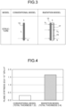
- FIG. 3 a conventional model including only a steel sheet (hat-shaped section part 13) is illustrated as a model for evaluating plane stiffness of a side wall portion 13b of the battery case cross member 19 in the related art (see FIG. 2 ).
- an invention model having a sandwich structure is illustrated in FIG. 3 as a model for evaluating the plane stiffness of the side wall portion 13b of the battery case cross member 5 of the present embodiment (see FIG. 1(b) ).
- parts corresponding to those in FIG. 1 and FIG. 2 are denoted by the same reference signs.
- the plane stiffness of a case where only a steel sheet is included as in the conventional model is generally given by a product EI of Young's modulus E of a material and a geometrical moment of inertia I.
- EI of a case of the sandwich structure as in the invention model can be obtained by utilization of the following expression (1).
- L is a width of a laminated body
- i is a material
- n is the number of layers
- E i is a Young's modulus of the material i
- FIG. 4 A difference in the plane stiffness EI of a case where the conventional model and the invention model in FIG. 3 have substantially the same weight was compared, and a result thereof is illustrated in FIG. 4 .
- a thickness of the hat-shaped section part 13 of the conventional model is set to 1.2t (total thickness 1.2t)
- a thickness of the hat-shaped section part 13 of the present invention model is set to 0.6t
- a thickness of the resin 15 is set to 1.5t
- a thickness of the reinforcement 17 is set to 0.3t (total thickness 2.4t)
- the plane stiffness EI of each is calculated by utilization of the expression (1).
- the invention model was 0.97 when the weight of the conventional model was a reference (1.00).
- the plane stiffness of the invention model (1.65 ⁇ 10 -7 GPa ⁇ m 4 ) was improved to 5.3 times that of the conventional model (0.31 ⁇ 10 -7 GPa ⁇ m 4 ).
- the hat-shaped section part 13 (made of metal) of the invention model is made thinner than that of the conventional model and replaced with the resin 15 having the lower density and the lower Young's modulus than metal, and the total thickness of the sandwich structure with the reinforcement 17 is made thicker than the sheet thickness of the conventional model.
- the invention model can significantly increase the plane stiffness even with the same degree of weight as the conventional model.
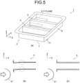
- FIG. 5 is a view for describing a deformed state of the battery case cross member 5 of a case where a side surface of the vehicle body crashes into a pole 21.
- FIG. 5(a) is a perspective view of the battery case 1
- FIG. 5(b) and FIG. 5(c) are plan views of cut sections taken along xy planes indicated by broken lines in FIG. 5(a) .
- broken lines in FIG. 5(b) and FIG. 5(c) represent an original shape of the battery case cross member 5.
- other components such as a side sill is present outside the vehicle body of the battery case 1 in an actual vehicle body, these components are not illustrated in FIG. 5 .
- the side wall portion 13b undergoes out-of-plane deformation.
- the side wall portion 13b is more easily deformed than the top portion 13a.
- improving the plane stiffness of the side wall portion 13b by providing the resin 15 and the reinforcement 17 on the side wall portion 13b improves the yield strength against the bending mode of the battery case cross member 5 and is effective.
- the battery case cross member 5 is maintained in the original shape thereof even at the time of the side crash.
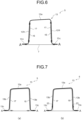
- providing the resin 15 and the reinforcement 17 only on the side wall portion 13b of the hat-shaped section part 11 is effective for deformation in the bending mode, and weight reduction can be expected.
- the hat-shaped section part 13 and the resin 15, and the reinforcement 17 integrally receive the load and the plane stiffness is effectively improved, the hat-shaped section part 13 and the resin 15, and the resin 15 and the reinforcement 17 need to be adhered with predetermined strength. This point will be described with a specific example.
- the plane stiffness EI is 2.72 ⁇ 10 -7 GPa ⁇ m 4 .
- the Young's modulus of iron was 206 GPa
- the Young's modulus of the resin 15 was 2 GPa.
- the plane stiffness EI of the adhered hat-shaped section part 13 and resin 15 is 0.19 ⁇ 10 -7 GPa ⁇ m 4
- the plane stiffness EI of the reinforcement 17 alone is 0.04 ⁇ 10 -7 GPa ⁇ m 4
- the total is 0.23 ⁇ 10 -7 GPa ⁇ m 4
- the plane stiffness as a whole is significantly decreased.
- the adhesive strength is preferably 5 MPa or more, for example.
- an adhesive is not debonded from the steel sheet in a case of bending deformation up to about 90° in the deformation in the bending mode in which the battery case cross member 5 is bent and folded in one side wall direction.
- the end portion of the battery case cross member 5 may be axially crushed and buckling-deformed into a bellows shape at an initial stage of the crash, and a deformation amount is larger than that of the bending deformation.
- yield strength at the time of the next (bellows) deformation decreases.
- the thickness of the resin 15 of the battery case cross member 5 is not limited in the present invention.
- the effect of improving the plane stiffness of the side wall portion 13b may be decreased when the resin 15 is too thin, and the effect of weight reduction may be decreased when the resin 15 is too thick.
- an example of a method of determining such a resin thickness will be described.
- the hat-shaped section part 13 to be a base for examination is prepared, and the weight and the plane stiffness of the side wall portion 13b are obtained.
- the hat-shaped section part 13 made of a steel sheet having the sheet thickness of 1.6 mm was prepared, and the weight (including the weight of the bottom portion 7) and the plane stiffness of the side wall portion 13b were obtained (see ⁇ base>> in Table 1 in the following).
- the hat-shaped section part 13 included in the battery case cross member 5 one having a sheet thickness thinner than the sheet thickness of the hat-shaped section part 13 serving as the base is prepared.
- three types of hat-shaped section parts 13 having the sheet thicknesses of 0.8 mm ⁇ No. 1>>, 1.0 mm ⁇ No. 2>>, and 1.2 mm ⁇ No. 3>> were prepared.
- the reinforcement 17 was made of a steel sheet having a sheet thickness of 0.4 mm (common to ⁇ No. 1>> to ⁇ No. 3>>).
- the sheet thickness of the hat-shaped section part 13 is made thinner than that of ⁇ base>>, and the resin 15 having the Young's modulus lower than that of the steel sheet is provided.
- the total thickness of the sandwich structure with the reinforcement 17 was made thicker than the sheet thickness of ⁇ base>>, the same degree of plane stiffness as the plane stiffness of ⁇ base>> (0.70 ⁇ 10 -7 GPa ⁇ m 4 ) was secured, and the effect of weight reduction by utilization of the resin 15 having the density lower than that of the steel sheet was maximized.
- the weight reduction rates are 21% for ⁇ No. 1>>, 12% for ⁇ No. 2>>, and 4% for ⁇ No. 3>>.
- the resin thickness is determined with the resin thickness of a case of A in which the weight can be maximally reduced without reduction of the plane stiffness as compared with ⁇ base>> being set as a lower limit, and the resin thickness of a case of B in which the plane stiffness can be maximally improved without an increase in the weight as compared with ⁇ base>> being set an upper limit.
- the resin thickness is set within a range of 0.45 mm to 4.0 mm.
- the thickness of the resin 15 can be determined in consideration of the balance between the weight reduction and the improvement in plane stiffness (bending stiffness).
- the battery case cross member 5 includes the resin 15 patched on or coating the inner surface of the hat-shaped section part 13, and the reinforcement 17 arranged to cover the resin 15 and adhered.
- the stiffness of the battery case cross member 5 is improved, deformation of the battery case 1 at the time of the side crash is controlled as compared with the related art, and the weight of the battery case cross member 5 can be reduced.
- an installation position of the battery case cross member 5 is not limited, a degree of freedom in battery case design is not reduced, and the volume of the battery case 1 is not reduced.
- the present embodiment can also improve vibration-damping properties. This point will be specifically described in examples described later.
- a resin 15 and a reinforcement 17 may be provided on an outer surface of s hat-shaped section part 13.
- a resin 15 and a reinforcement 17 may be provided on each of an inner surface and an outer surface of a hat-shaped section part 13.
- the present invention has a characteristic in a configuration of the battery case cross member 5 that is one component of the battery case 1.
- the present invention also includes an invention as a battery case cross member alone. Since an embodiment of the battery case cross member 5 is similar to the above description, the description thereof is omitted.
- the battery case cross member 5 having the hat-shaped cross section has been described in the above embodiment, the battery case cross member 5 according to the present invention is not limited to one having the hat-shaped cross section.
- a tunnel-shaped part having a flange portion at a lower end portion of each of side walls and having a tunnel shape as a whole may be used.
- a dome-shaped member includes an aspect in which a portion formed of three planes of the side wall portions 13b and the top portion 13a in the hat-shaped cross section is not formed of three planes but formed of two planes or four planes or more (rectangular dome shape), and an aspect in which the portion is formed of a curved surface instead of a plane (general dome shape).
- a cylindrical test body (200 mm in length) including a component that has a hat-shaped cross section and that corresponds to the battery case cross member 5, and a flat plate corresponding to the bottom portion 7 of the battery case 1 was prepared, and a crash test of evaluating crash worthiness and an impact vibration test of evaluating vibration characteristics were performed.
- a load was input in an axial direction (longitudinal direction) of the test body with an impact punch at a test speed of 8.9 m/s, and the test body was deformed for 20 mm from 200 mm to 180 mm in the axial direction.
- a load-stroke curve was obtained by measurement of the load generated in a support portion of the test body and a stroke of the impact punch (amount of axial crush deformation), and a maximum load (kN) of the load-stroke curve was defined as yield strength against the crash (referred to as crash yield strength) of the test body.
- the maximum value of the crash yield strength indicates a load at the time of a change to plastic deformation through elastic deformation immediately after a start of the axial crush deformation, and it can be said that the deformation at the time of the crash is less likely to be generated and the crash worthiness is better as this value becomes higher.
- an acceleration sensor was attached near an edge of the top portion 13a of the suspended test body, and impact vibration was applied to the side wall portions 13b of the test body with an impact hammer. Then, impact force obtained from the impact hammer and acceleration measured in the test body were taken into a fast Fourier transform (FFT) analyzer, and a frequency response function of accelerance (m/s 2 /N) was calculated. The frequency response function was obtained by averaging processing of results of the five times of impact tests.
- FFT fast Fourier transform
- a battery case cross member 5 is made of a material having 1180 MPa and a sheet thickness of 1.6 mm
- a flat plate (member corresponding to a bottom portion 7 of a battery case lower 11) is made of a material having 440 MPa and a sheet thickness of 0.7 mm.
- weight was 3.32 kg
- accelerance at 200 Hz which accelerance was obtained in the impact test was 200 m/s 2 /N.
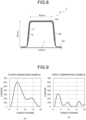
- crash yield strength indicating crash performance corresponds to the maximum load of the load-stroke curve (see FIG. 9 ) obtained by the crash test, and was 310 kN in the first comparative example.
- a material having 1180 MPa and a sheet thickness of 1.0 mm is used for a battery case cross member 5
- a material having 440 MPa and a sheet thickness of 0.7 mm is used for a flat plate (member corresponding to a bottom portion 7 of a battery case lower 11)
- a resin thickness is 2 mm
- a material having 270 MPa and a sheet thickness of 0.4 mm is used for a reinforcement 17.
- a method of joining the reinforcement 17 is illustrated in FIG. 1(b) .
- weight was 3.23 kg
- crash yield strength was 370 kN
- accelerance at 200 Hz in the impact test was 1 m/s 2 /N. While the weight was reduced by 0.09 kg as compared with the first comparative example, the crash yield strength was improved by 60 kN, and a vibration (accelerance) could be greatly controlled.
- a battery case cross member 5 is made of a material having 1470 MPa and a sheet thickness of 1.2 mm, and a flat plate (member corresponding to a bottom portion 7 of a battery case lower 11) is made of a material having 440 MPa and a sheet thickness of 0.7 mm.
- a resin thickness is 0.2 mm, and a material having 270 MPa and a sheet thickness of 0.4 mm is used for a reinforcement 17.
- a method of joining the reinforcement 17 is illustrated in FIG. 1(b) .
- weight was 3.19 kg
- crash yield strength was 320 kN
- accelerance at 200 Hz in the impact test was 2 m/s 2 /N.
- a battery case cross member 5 is made of a material having 1470 MPa and a sheet thickness of 1.0 mm
- a flat plate (member corresponding to a bottom portion 7 of a battery case lower 11) is made of a material having 440 MPa and a sheet thickness of 0.7 mm.
- a resin thickness is 2 mm
- a material having 270 MPa and a sheet thickness of 0.2 mm is used for a reinforcement 17.
- a method of joining the reinforcement 17 is illustrated in FIG. 1(b) .
- the weight was 2.97 kg
- the crash yield strength was 310 kN
- the accelerance at 200 Hz in the impact test was 1 m/s 2 /N.
- the structure is the lightest in the invention examples, and the crash yield strength was equivalent and the vibration-damping properties was significantly improved while the weight was reduced for 0.35 kg as compared with the first comparative example.
- a battery case cross member 5 is made of a material having 980 MPa and a sheet thickness of 1.2 mm, and a flat plate (member corresponding to a bottom portion 7 of a battery case lower 11) is made of a material having 440 MPa and a sheet thickness of 0.7 mm.
- a resin thickness is 5 mm, and a material having 270 MPa and a sheet thickness of 0.6 mm is used for a reinforcement 17.
- a method of joining the reinforcement 17 is illustrated in FIG. 1(b) .
- weight was 4.43 kg and was increased as compared with the first comparative example.
- crash yield strength was 600 kN and was almost twice as high as that in the first comparative example. Accelerance at 200 Hz in the impact test was 1 m/s 2 /N, and a vibration could be greatly controlled.
- a method of joining a reinforcement 17 is in a manner illustrated in FIG. 7(a) , and other conditions are the same as those in the first invention example.
- an end portion of the reinforcement 17 is joined to a flat plate (member corresponding to a bottom portion 7 of a battery case lower 11).
- weight is 3.31 kg and is increased as compared with the first invention example but is decreased as compared with the first comparative example.
- crash yield strength was 380 kN and was improved as compared with the first invention example.
- a method of joining the reinforcement 17 is in a manner illustrated in FIG. 7(b) , and other conditions are the same as those in the first invention example.
- the joining method illustrated in FIG. 7(b) is the same as that in FIG. 1(b) in a point that the lower end portion of the reinforcement 17 is joined to the lower end portion of the side wall.
- joining protrusions 23 are provided at predetermined intervals in a longitudinal direction at a lower end portion of the reinforcement 17, and the joining protrusions 23 are joined to a peripheral wall of a side wall portion 13b of a hat-shaped section part 13.
- a resin 15 can be patched to the lower end of the reinforcement 17, and a patched amount of the resin 15 can be increased.
- weight was 3.32 kg, was increased as compared with the first invention example, and was the same as that of the first comparative example.
- crash yield strength was 380 kN and was improved as compared with the first invention example.
- a resin 15 and a reinforcement 17 are provided only on a side wall portion 13b of the hat-shaped section part 11, and the other conditions are the same as those of the first invention example.
- weight was 3.02 kg
- crash yield strength was 364 kN
- accelerance at 200 Hz in the impact test was 2 m/s 2 /N.
- the crash yield strength and the vibration (accelerance) were at a level equivalent to those of the first invention example
- the crash yield strength was improved by 54 kN as compared with the first comparative example, and the vibration-damping properties were also significantly improved.
- the first to third and fifth invention examples can reduce the weight while securing the plane stiffness, the crash yield strength, and the vibration-damping properties equivalent to or higher than those of the first comparative example.
- the fourth invention example although the weight is increased as compared with the first comparative example, the crash yield strength is almost doubled and the effect of improving the crash performance is high as compared with the increase in the weight. Thus, it is effective in a case where higher crash performance is required.
- the sixth invention example in which the weight is the same as that of the first comparative example and the crash yield strength is high.
- the present invention it is possible to provide a battery case and a battery case cross member capable of realizing stiffness, weight reduction, and vibration-damping properties better than those of a related art without reducing the volume of the battery case.
Landscapes
- Engineering & Computer Science (AREA)
- Chemical & Material Sciences (AREA)
- Chemical Kinetics & Catalysis (AREA)
- Electrochemistry (AREA)
- General Chemical & Material Sciences (AREA)
- Mechanical Engineering (AREA)
- Transportation (AREA)
- Sustainable Energy (AREA)
- Sustainable Development (AREA)
- Power Engineering (AREA)
- Life Sciences & Earth Sciences (AREA)
- Aviation & Aerospace Engineering (AREA)
- Combustion & Propulsion (AREA)
- Battery Mounting, Suspending (AREA)
- Sealing Battery Cases Or Jackets (AREA)
- Arrangement Or Mounting Of Propulsion Units For Vehicles (AREA)
- Body Structure For Vehicles (AREA)
Abstract
Description
- The present invention relates to a battery case of an automobile and a battery case cross member used for the battery case.
- A battery case cross member is provided as a stiffing member in a battery case installed under a floor of an automobile. The battery case cross member is set inside the battery case in such a manner that an axial direction is a vehicle width direction, and has a function of controlling a deformation of the battery case due to an input load from a side sill at the time of side crash of the automobile and preventing breakage of a battery inside the battery case.
- In order to effectively exhibit such a function, the battery case cross member is a component requiring a high level of strength. In addition, at the present time at which weight reduction of an automatic body of the automobile is required, a technique of forming a battery case with light metal such as an aluminum alloy has been studied.
- As a related art of a structure of the battery case, for example, there are structures described in
Patent Literature 1 and Patent Literature 2.Patent Literature 1 describes a structure in which a reinforcing member that reinforces a battery case container main body (described as a tray in Patent Literature 1) in a vehicle width direction sandwiches the tray from an upper surface and a lower surface, or the reinforcing member is arranged on any one of the upper surface or the lower surface of the tray. - Furthermore, Patent Literature 2 describes a structure in which a battery case container main body is formed of a deep drawn product made of a 5000-series aluminum alloy. In this structure, the battery case includes at least one internal reinforcing member in a vehicle front-rear direction and right-left direction inside the container main body, and the internal reinforcing member is made of a 7000-series aluminum alloy.
-
- Patent Literature 1:
Japanese Patent Application Laid-open No. 2019-81436 - Patent Literature 2:
Japanese Patent Application Laid-open No. 2021-68523 - In the structure described in
Patent Literature 1, there remains a problem of further reducing weight of an automotive body in order to increase a cruising distance of a battery electric vehicle. On the other hand, the structure described in Patent Literature 2 has a characteristic that the 7000-series aluminum alloy having high strength among aluminum alloys is used for the reinforcing member. However, the 7000-series aluminum alloy has only about 300 MPa to 400 MPa of 0.2% yield strength. Thus, it is necessary to increase a thickness of a member of the battery case cross member in order to control deformation of the battery case, and there are problems of an increase in weight and an increase in cost. - As described above, although there are techniques of preventing the deformation of the battery case due to the input load from the side sill at the time of the side crash of the automobile, these techniques have problems of the increase in weight and the increase in cost.
- The present invention has been made to solve the above problems, and an object thereof is to provide a battery case and a battery case cross member capable of realizing stiffness, weight reduction, and vibration-damping properties better than those in a related art without reducing a battery case volume.
- A battery case according to a first aspect of the present invention is mounted under a floor of a vehicle body to store a battery and includes: a main body formed of a bottomed frame body having side walls facing each other in a vehicle width direction in a state of being mounted on the vehicle body; and a battery case cross member configured to extend between the facing side walls in the main body and to reinforce the main body, the battery case cross member including a hat-shaped section part including a top portion, side wall portions, and flange portions, the flange portions abutting on a bottom surface of the main body, a resin patched on or coating a full length of an inner surface and/or outer surface of the hat-shaped section part, and a reinforcement arranged to cover the resin and adhered to the resin.
- A battery case according to a second aspect of the present invention is mounted under a floor of a vehicle body to store a battery and includes: a main body formed of a bottomed frame body having side walls facing each other in a vehicle width direction in a state of being mounted on the vehicle body; and a battery case cross member configured to extend between the facing side walls in the main body and reinforce the main body, the battery case cross member including a tunnel-shaped part having a tunnel shape as a whole and including a flange portion at a lower end portion of each of side walls, a resin patched on or coating a full length of an inner surface and/or outer surface of the tunnel-shaped part, and a reinforcement arranged to cover the resin and adhered to the resin.
- A thickness of the resin may be 0.1 to 5 mm, and a thickness of the reinforcement may be 0.15 to 1 mm.
- An end portion of the reinforcement may be joined to each of the side wall portions of the hat-shaped section part or the peripheral wall of the tunnel-shaped part.
- Joining protrusions may be formed at the end portion of the reinforcement at predetermined intervals in a longitudinal direction, and the joining protrusions may be joined to each of the side wall portions of the hat-shaped section part or the peripheral wall of the tunnel-shaped part.
- An end portion of the reinforcement may be joined to the bottom surface of the main body.
- A battery case cross member according to the first aspect of the present invention is provided in a main body of a battery case to extend between facing side walls of the main body and reinforcing the main body, the main body being formed of a bottomed frame body having the facing side walls, and the battery case being configured to store a battery in the main body, and includes: a hat-shaped section part including a top portion, side wall portions, and flange portions, the flange portions abutting on a bottom surface of the main body in a state of being installed in the battery case; a resin patched on or coating a full length of an inner surface and/or outer surface of the hat-shaped section part; and a reinforcement arranged to cover the resin and adhered to the resin.
- A battery case cross member according to the second aspect of the present invention is provided in a main body of a battery case to extend between facing side walls of the main body and reinforcing the main body, the main body being formed of a bottomed frame body having the facing side walls, and the battery case being configured to store a battery in the main body, and includes: a tunnel-shaped part including an opening in a part of a peripheral wall, and a flange portion in the opening; a resin patched on or coating a full length of an inner surface and/or outer surface of the tunnel-shaped part; and a reinforcement arranged to cover the resin and adhered to the resin.
- A thickness of the resin may be 0.1 to 5 mm, and a thickness of the reinforcement may be 0.15 to 1 mm.
- An end portion of the reinforcement may be joined to each of the side wall portions of the hat-shaped section part or the peripheral wall of the tunnel-shaped part.
- Joining protrusions may be formed at the end portion of the reinforcement at predetermined intervals in a longitudinal direction, and the joining protrusions may be joined to each of the side wall portions of the hat-shaped section part or the peripheral wall of the tunnel-shaped part.
- An end portion of the reinforcement may be joined to the bottom surface of the main body.
- According to a battery case of the present invention, deformation of the battery case at the time of a side crash can be controlled by an improvement in stiffness of a battery case cross member, and weight reduction and vibration-damping properties of the battery case can also be improved. In addition, since an appearance of the battery cross member hardly changes, the volume does not decrease as compared with a battery case of related art.
-
-
FIG. 1 is a view for describing a battery case according to an embodiment of the present invention,FIG. 1(a) being a perspective view, andFIG. 1(b) being a cross-sectional view taken along a line A-A ofFIG. 1(a) . -
FIG. 2 is a view illustrating a cross section of a battery case cross member of a related art as a comparative example of the battery case cross member ofFIG. 1 . -
FIG. 3 is a view for describing a model of evaluating plane stiffness of a side wall portion of the battery case cross member inFIG. 1 (invention model), and a model of evaluating plane stiffness of a side wall portion of the battery case cross member in the related art inFIG. 2 (conventional model). -
FIG. 4 is a graph illustrating results of evaluating plane stiffness of the conventional model and the invention model inFIG. 3 . -
FIG. 5 is a view of describing a deformed state of the battery case cross member at the time of a side crash. -
FIG. 6 is a view illustrating another aspect of a cross section of the battery case cross member ofFIG. 1 . -
FIG. 7 is a view for describing another aspect of a joining method of a reinforcement in the battery case cross member. -
FIG. 8 is a view for describing a resin coating (patching) range and a specific dimension in a circumferential direction of a test body of an invention example according to an example. -
FIG. 9 is a view illustrating load-stroke curves during a crash test in a fourth invention example and a first comparative example according to the example. - A
battery case 1 of an automobile according to an embodiment of the present invention will be described with reference toFIG. 1 . Thebattery case 1 according to the present embodiment is mounted under a floor of a vehicle body, stores a battery, and includes amain body 3, and a batterycase cross member 5 that is provided in such a manner as to extend between facingside walls 9 in themain body 3 and that reinforces themain body 3. Each configuration will be described below. - The
main body 3 stores a battery of a battery electric vehicle. Themain body 3 includes a battery case lower 11 formed of a bottomed frame body including arectangular bottom portion 7 andside walls 9 erected on a peripheral edge of thebottom portion 7, and a battery case upper (not illustrated) that is a lid covering the battery case lower 11. - The battery
case cross member 5 is a stiffing member that improves stiffness of thebattery case 1, and controls deformation of thebattery case 1 at the time of a side crash. - As illustrated in
FIG. 1(b) , the batterycase cross member 5 includes a hat-shaped section part 13, aresin 15 patched on or coating an inner surface of the hat-shaped section part 13, and areinforcement 17 provided in such a manner as to cover theresin 15. - The hat-
shaped section part 13 is a member made of metal (such as a steel sheet) having a hat-shaped cross section and includes atop portion 13a,side wall portions 13b, andflange portions 13c. Theflange portions 13c of the hat-shaped section part 13 are joined to thebottom portion 7 of the battery case lower 11. In addition, both end portions of theside wall portions 13b are respectively joined to the facingside walls 9. As a material of the hat-shaped section part 13, for example, a high strength steel sheet of 980 MPa or more is used in order to enhance strength and stiffness. - The
resin 15 of predetermined adhesive strength is patched on or coating an inner surface of each of theside wall portions 13b of the hat-shaped section part 13. Theresin 15 may be molded in advance (as an injection-molded resin component) and patched on the hat-shaped section part 13, or may be formed by coating of theresin 15 before molding to the hat-shaped section part 13 and by baking. - A lower limit of a thickness of the
resin 15 is about 0.1 mm that can uniformly coat in a case of forming theresin 15 by coating, and is about 20 µm in a case where the film-shaped resin 15 is patched. An upper limit of the thickness of theresin 15 is preferably about 5 mm from a viewpoint of cost. - Furthermore, the
reinforcement 17 is provided in such a manner as to cover theresin 15. Thereinforcement 17 prevents theresin 15 from being debonded from theside wall portion 13b of the hat-shapedsection part 13, and improves the plane stiffness of theside wall portion 13b in cooperation with theresin 15 as described later, whereby the stiffness of the batterycase cross member 5 is improved. Thereinforcement 17 is fixed to theside wall portion 13b of the hat-shapedsection part 13 by spot welding. In addition, thereinforcement 17 and theresin 15 are adhered to each other with predetermined strength. - The effect of improving the plane stiffness of the
side wall portion 13b in the present embodiment does not largely depend on tensile strength of the material of thereinforcement 17 as described later. Thus, the tensile strength may be lower than that of the material of the hat-shapedsection part 13, and 270 MPa-class to 590 MPa-class tensile strength may be employed from a viewpoint of reducing a manufacturing cost. Furthermore, thereinforcement 17 only needs to prevent debonding of theresin 15 from theside wall portion 13b of the hat-shapedsection part 13. Thus, a sheet thickness of thereinforcement 17 may be thinner than a sheet thickness of the material of the hat-shapedsection part 13, and a steel sheet having a sheet thickness of 0.15 to 1 mm is preferable from a viewpoint of weight reduction and manufacturing cost reduction. - The tensile strength is set to the 270 MPa-class to the 590 MPa-class since the tensile strength is the lowest in a usually-used steel sheet at the 270 MPa-class, and cost is greatly increased when the 590 MPa-class is exceeded. Within this range, specifically, the 270 MPa-class (so-called mild steel) that is a grade of an inexpensive general cold rolled steel sheet called common steel such as SPCC of the Japan Industrial Standard (JIS) is preferable from a viewpoint of cost. In addition, the sheet thickness is set to 0.15 to 1 mm since the manufacturing cost increases when the sheet thickness is less than 0.15 mm, and a weight reduction effect decreases when the sheet thickness exceeds 1 mm.
- As illustrated in
FIG. 2 , a general batterycase cross member 19 in a related art only includes a metal hat-shapedsection part 13. However, in this case, in order to improve strength and stiffness, it is necessary to increase a sheet thickness of the hat-shapedsection part 13, and weight is increased. - In this point, in the battery
case cross member 5 of the present embodiment in which theresin 15 and thereinforcement 17 are provided on the hat-shapedsection part 13, an apparent sheet thickness of the portion where theresin 15 and the reinforcing 17 are provided is thick. However, since theresin 15 having density lower than that of metal is used, the weight is less likely to increase as compared with a case where the sheet thickness of the hat-shapedsection part 13 itself is increased as in the related art. - Furthermore, since a sandwich structure in which the
resin 15 is sandwiched between the metal hat-shapedsection part 13 and thereinforcement 17 is employed, the plane stiffness of theside wall portion 13b can be improved. The plane stiffness of theside wall portion 13b is stiffness before a load is input in an in-plane direction of theside wall portion 13b from the end portion of theside wall portion 13b and buckling deformation is started (bending stiffness). This point will be described with reference toFIG. 3 and FIG. 4 . - In
FIG. 3 , a conventional model including only a steel sheet (hat-shaped section part 13) is illustrated as a model for evaluating plane stiffness of aside wall portion 13b of the batterycase cross member 19 in the related art (seeFIG. 2 ). In addition, an invention model having a sandwich structure (three-layer laminate structure) is illustrated inFIG. 3 as a model for evaluating the plane stiffness of theside wall portion 13b of the batterycase cross member 5 of the present embodiment (seeFIG. 1(b) ). InFIG. 3 , parts corresponding to those inFIG. 1 and FIG. 2 are denoted by the same reference signs. - The plane stiffness of a case where only a steel sheet is included as in the conventional model is generally given by a product EI of Young's modulus E of a material and a geometrical moment of inertia I. On the other hand, the plane stiffness EI of a case of the sandwich structure as in the invention model can be obtained by utilization of the following expression (1).

- In the above expression (1), L is a width of a laminated body, i is a material, n is the number of layers, Ei is a Young's modulus of the material i, hi is a thickness from a material of i = 1 to a layer of the material i, and λ is a distance from a surface of the material of i = 1 to a neutral plane of the laminated body.
- A difference in the plane stiffness EI of a case where the conventional model and the invention model in
FIG. 3 have substantially the same weight was compared, and a result thereof is illustrated inFIG. 4 . InFIG. 4 , a thickness of the hat-shapedsection part 13 of the conventional model is set to 1.2t (total thickness 1.2t), a thickness of the hat-shapedsection part 13 of the present invention model is set to 0.6t, a thickness of theresin 15 is set to 1.5t, and a thickness of thereinforcement 17 is set to 0.3t (total thickness 2.4t), and the plane stiffness EI of each is calculated by utilization of the expression (1). In a weight ratio of the both models inFIG. 4 , the invention model was 0.97 when the weight of the conventional model was a reference (1.00). - As illustrated in
FIG. 4 , the plane stiffness of the invention model (1.65 × 10⁻⁷ GPa·m4) was improved to 5.3 times that of the conventional model (0.31 × 10⁻⁷ GPa·m4). As described above, the hat-shaped section part 13 (made of metal) of the invention model is made thinner than that of the conventional model and replaced with theresin 15 having the lower density and the lower Young's modulus than metal, and the total thickness of the sandwich structure with thereinforcement 17 is made thicker than the sheet thickness of the conventional model. As a result, the invention model can significantly increase the plane stiffness even with the same degree of weight as the conventional model. - Next, a reason why the
resin 15 and thereinforcement 17 are provided on theside wall portion 13b of the hat-shapedsection part 13 will be described with reference toFIG. 5. FIG. 5 is a view for describing a deformed state of the batterycase cross member 5 of a case where a side surface of the vehicle body crashes into apole 21.FIG. 5(a) is a perspective view of thebattery case 1, andFIG. 5(b) and FIG. 5(c) are plan views of cut sections taken along xy planes indicated by broken lines inFIG. 5(a) . Furthermore, broken lines inFIG. 5(b) and FIG. 5(c) represent an original shape of the batterycase cross member 5. Although other components such as a side sill is present outside the vehicle body of thebattery case 1 in an actual vehicle body, these components are not illustrated inFIG. 5 . - When the
pole 21 is located at a position illustrated inFIG. 5(b) and a left side surface of the vehicle body in the drawing crashes into thepole 21, deformation of the batterycase cross members 5 on both sides of the portion crashing into thepole 21 is often a bending mode (solid line inFIG. 5(b) ) of being bent toward the crash portion. - At the time of deformation in the bending mode as illustrated in
FIG. 5(b) , while thetop portion 13a undergoes in-plane deformation, theside wall portion 13b undergoes out-of-plane deformation. Thus, theside wall portion 13b is more easily deformed than thetop portion 13a. Thus, improving the plane stiffness of theside wall portion 13b by providing theresin 15 and thereinforcement 17 on theside wall portion 13b improves the yield strength against the bending mode of the batterycase cross member 5 and is effective. By improvement of the plane stiffness of theside wall portion 13b, as illustrated inFIG. 5(c) , the batterycase cross member 5 is maintained in the original shape thereof even at the time of the side crash. In addition, as illustrated inFIG. 6 , providing theresin 15 and thereinforcement 17 only on theside wall portion 13b of the hat-shapedsection part 11 is effective for deformation in the bending mode, and weight reduction can be expected. - Since the hat-shaped
section part 13, theresin 15, and thereinforcement 17 integrally receive the load and the plane stiffness is effectively improved, the hat-shapedsection part 13 and theresin 15, and theresin 15 and thereinforcement 17 need to be adhered with predetermined strength. This point will be described with a specific example. - For example, in a case where the sheet thickness of the hat-shaped
section part 13 is 1.0 mm, the thickness of theresin 15 is 1.0 mm, and the sheet thickness of the reinforcement 17 (made of iron) is 0.6 mm, when the hat-shapedsection part 13 and theresin 15, and theresin 15 and thereinforcement 17 are adhered to each other, the plane stiffness EI is 2.72 × 10⁻⁷ GPa·m4. Here, the Young's modulus of iron was 206 GPa, and the Young's modulus of theresin 15 was 2 GPa. In a case where theresin 15 and thereinforcement 17 are not adhered to each other, the plane stiffness EI of the adhered hat-shapedsection part 13 andresin 15 is 0.19 × 10⁻⁷ GPa·m4, and the plane stiffness EI of thereinforcement 17 alone is 0.04 × 10⁻⁷ GPa·m4. Thus, the total is 0.23 × 10⁻⁷ GPa·m4, and the plane stiffness as a whole is significantly decreased. Thus, it is important that the hat-shapedsection part 13 and theresin 15 are adhered with sufficient strength and theresin 15 and thereinforcement 17 are adhered with sufficient strength in such a manner that the hat-shapedsection part 13, theresin 15, and thereinforcement 17 can integrally receive the load. - The adhesive strength is preferably 5 MPa or more, for example. When the adhesive strength is 5 MPa or more, an adhesive is not debonded from the steel sheet in a case of bending deformation up to about 90° in the deformation in the bending mode in which the battery
case cross member 5 is bent and folded in one side wall direction. The end portion of the batterycase cross member 5 may be axially crushed and buckling-deformed into a bellows shape at an initial stage of the crash, and a deformation amount is larger than that of the bending deformation. When theresin 15 is debonded at the initial stage of the deformation, yield strength at the time of the next (bellows) deformation decreases. Thus, it is more preferable to set the adhesive strength to 10 MPa or more at a portion where large deformation such as axial crushing is assumed. - With respect to a patching (or coating) range of the
resin 15 in a longitudinal direction of the batterycase cross member 5, it is preferable to provide theresin 15 over a full length in the longitudinal direction. - As described above, the thickness of the
resin 15 of the batterycase cross member 5 is not limited in the present invention. However, the effect of improving the plane stiffness of theside wall portion 13b may be decreased when theresin 15 is too thin, and the effect of weight reduction may be decreased when theresin 15 is too thick. Thus, it is preferable to determine the resin thickness in consideration of a balance between the two. Hereinafter, an example of a method of determining such a resin thickness will be described. - First, the hat-shaped
section part 13 to be a base for examination is prepared, and the weight and the plane stiffness of theside wall portion 13b are obtained. Here, the hat-shapedsection part 13 made of a steel sheet having the sheet thickness of 1.6 mm was prepared, and the weight (including the weight of the bottom portion 7) and the plane stiffness of theside wall portion 13b were obtained (see <<base>> in Table 1 in the following). - Next, as the hat-shaped
section part 13 included in the batterycase cross member 5 according to the present embodiment, one having a sheet thickness thinner than the sheet thickness of the hat-shapedsection part 13 serving as the base is prepared. Here, three types of hat-shapedsection parts 13 having the sheet thicknesses of 0.8 mm <<No. 1>>, 1.0 mm <<No. 2>>, and 1.2 mm <<No. 3>> were prepared. Thereinforcement 17 was made of a steel sheet having a sheet thickness of 0.4 mm (common to <<No. 1>> to <<No. 3>>). - In a case where the battery
case cross member 5 in a manner illustrated inFIG. 1 is configured by utilization of the hat-shapedsection parts 13 of <<No. 1>> to <<No. 3>> and thereinforcement 17, the resin thickness of when the plane stiffness of theside wall portion 13b is adjusted to be the same degree as the plane stiffness of <<base>> was obtained (A). In addition, the resin thickness of when the weight of the batterycase cross member 5 was adjusted to be the same degree as the weight of <<base>> was obtained (B). Results are illustrated in Table 1. Weight in Table 1 also includes the weight of the bottom portion 7 (0.9 kg in common). In addition, the plane stiffness is assumed to be that in theside wall portion 13b.Table 1 No Resin thickness determination A. Constant plane stiffness B. Constant weight Sheet thickness of hat-shaped section part hc/mm Resin thickness hj/mm Sheet thickness of reinforcement hp/mm Total thickness hc+hj+hp/mm Weight *including bottom portion /kg Weight reduction rate /% m Plane stiffness of side wall portion ×10-7 GPa·m4 Plane stiffness improvement rate /% Base - 1.60 - - 1.60 3.59 - 0.70 - 1 A 0.80 0.45 0.40 1.65 2.85 21 0.71 1% B 0.80 4.00 0.40 5.20 3.56 1 11.89 1599% 2 A 1.00 0.25 0.40 1.65 3.15 12 0.71 1% B 1.00 2.50 0.40 3.90 3.60 0 6.27 796% 3 A 1.20 0.02 0.40 1.62 3.44 4 0.72 3% B 1.20 0.80 0.40 2.40 3.60 0 1.90 171% *Weight of bottom portion is 0.9 kg (in common) - In A of <<No. 1>> to <<No. 3>> illustrated in Table 1, the sheet thickness of the hat-shaped
section part 13 is made thinner than that of <<base>>, and theresin 15 having the Young's modulus lower than that of the steel sheet is provided. In addition, in A of <<No. 1>> to <<No. 3>>, the total thickness of the sandwich structure with thereinforcement 17 was made thicker than the sheet thickness of <<base>>, the same degree of plane stiffness as the plane stiffness of <<base>> (0.70 × 10⁻⁷ GPa·m4) was secured, and the effect of weight reduction by utilization of theresin 15 having the density lower than that of the steel sheet was maximized. The weight reduction rates are 21% for <<No. 1>>, 12% for <<No. 2>>, and 4% for <<No. 3>>. - On the other hand, in B of <<No. 1>> to <<No. 3>>, the resin thickness is increased until the weight becomes the same degree as the weight of <<base>> (3.59 kg), the total thickness of the sandwich structure is made thicker than that of A, and the effect of improving the plane stiffness is maximized. Plane stiffness improvement rates are 1599% for <<No. 1>>, 796% for <<No. 2>>, and 171% for <<No. 3>>.
- On the basis of the results in Table 1, the resin thickness is determined with the resin thickness of a case of A in which the weight can be maximally reduced without reduction of the plane stiffness as compared with <<base>> being set as a lower limit, and the resin thickness of a case of B in which the plane stiffness can be maximally improved without an increase in the weight as compared with <<base>> being set an upper limit. Thus, in a case of <<No. 1>> (the sheet thickness hc of the hat-shaped
section part 13 = 0.8 mm, and the sheet thickness hp of thereinforcement 17 = 0.4 mm), the resin thickness is set within a range of 0.45 mm to 4.0 mm. Similarly, the resin thickness is set within a range of 0.25 mm to 2.5 mm in a case of <<No. 2>> (the sheet thickness hc of the hat-shapedsection part 13 = 1.0 mm, and the sheet thickness hp of thereinforcement 17 = 0.4 mm), and may be set within a range of 0.02 mm to 0.8 mm in a case of <<No. 3>> (the sheet thickness hc of the hat-shapedsection part 13 = 1.2 mm, and the sheet thickness hp of thereinforcement 17 = 0.4 mm). In such a manner, the thickness of theresin 15 can be determined in consideration of the balance between the weight reduction and the improvement in plane stiffness (bending stiffness). - As described above, according to the present embodiment, the battery
case cross member 5 includes theresin 15 patched on or coating the inner surface of the hat-shapedsection part 13, and thereinforcement 17 arranged to cover theresin 15 and adhered. As a result, the stiffness of the batterycase cross member 5 is improved, deformation of thebattery case 1 at the time of the side crash is controlled as compared with the related art, and the weight of the batterycase cross member 5 can be reduced. In addition, since an installation position of the batterycase cross member 5 is not limited, a degree of freedom in battery case design is not reduced, and the volume of thebattery case 1 is not reduced. The present embodiment can also improve vibration-damping properties. This point will be specifically described in examples described later. - Although an example in which the
resin 15 and thereinforcement 17 are provided on the inner surface of the hat-shapedsection part 13 of the batterycase cross member 5 has been described in the above embodiment, the present invention is not limited thereto. Aresin 15 and areinforcement 17 may be provided on an outer surface of s hat-shapedsection part 13. In addition, aresin 15 and areinforcement 17 may be provided on each of an inner surface and an outer surface of a hat-shapedsection part 13. - Furthermore, although the embodiment as the
battery case 1 of the automobile has been described above, the present invention has a characteristic in a configuration of the batterycase cross member 5 that is one component of thebattery case 1. Thus, the present invention also includes an invention as a battery case cross member alone. Since an embodiment of the batterycase cross member 5 is similar to the above description, the description thereof is omitted. - Although the battery
case cross member 5 having the hat-shaped cross section has been described in the above embodiment, the batterycase cross member 5 according to the present invention is not limited to one having the hat-shaped cross section. A tunnel-shaped part having a flange portion at a lower end portion of each of side walls and having a tunnel shape as a whole may be used. A dome-shaped member includes an aspect in which a portion formed of three planes of theside wall portions 13b and thetop portion 13a in the hat-shaped cross section is not formed of three planes but formed of two planes or four planes or more (rectangular dome shape), and an aspect in which the portion is formed of a curved surface instead of a plane (general dome shape). - A specific experiment of evaluating an action and effect of the present invention has been conducted, and results will be described below. In the present example, a cylindrical test body (200 mm in length) including a component that has a hat-shaped cross section and that corresponds to the battery
case cross member 5, and a flat plate corresponding to thebottom portion 7 of thebattery case 1 was prepared, and a crash test of evaluating crash worthiness and an impact vibration test of evaluating vibration characteristics were performed. - In the crash test, a load was input in an axial direction (longitudinal direction) of the test body with an impact punch at a test speed of 8.9 m/s, and the test body was deformed for 20 mm from 200 mm to 180 mm in the axial direction. At that time, a load-stroke curve was obtained by measurement of the load generated in a support portion of the test body and a stroke of the impact punch (amount of axial crush deformation), and a maximum load (kN) of the load-stroke curve was defined as yield strength against the crash (referred to as crash yield strength) of the test body. The maximum value of the crash yield strength indicates a load at the time of a change to plastic deformation through elastic deformation immediately after a start of the axial crush deformation, and it can be said that the deformation at the time of the crash is less likely to be generated and the crash worthiness is better as this value becomes higher.
- In the impact vibration test, an acceleration sensor was attached near an edge of the
top portion 13a of the suspended test body, and impact vibration was applied to theside wall portions 13b of the test body with an impact hammer. Then, impact force obtained from the impact hammer and acceleration measured in the test body were taken into a fast Fourier transform (FFT) analyzer, and a frequency response function of accelerance (m/s2/N) was calculated. The frequency response function was obtained by averaging processing of results of the five times of impact tests. - Details of the invention examples and a comparative example as test bodies (tensile strength and sheet thicknesses of the hat-shaped
section part 13, the flat plate, and thereinforcement 17, a resin thickness, a resin/reinforcement patched position, a joining method of thereinforcement 17, an adhesive strength of theresin 15, and weight of each test body) and the results of the above tests are illustrated in Table 2. As an example of the load-stroke curve obtained in the crash test, load-stroke curves of the first comparative example and a fourth invention example are illustrated inFIG. 9 .Table 2 Hat-shaped section part Flat plate Resin Reinforcement Resin/ reinforcement patched position in longitudinal direction of component Resin/ reinforcement patched position in cross-sectional direction Joining method of reinforcement Adhesive strength Mpa Weight /kg Crash yield strength /kN Vibration damping Accelerance (200 Hz) m/s2/N Strength /Mpa Sheet thickness /mm Strength /Mpa Sheet thickness /mm Thickness /mm Strength /Mpa Sheet thickness /mm First invention example 1180 1.0 440 0.7 2.0 270 0.4 Full length Whole circumference FIG. 1(b) 10 3.23 370 1 Second invention example 1470 1.2 440 0.7 0.2 270 0.4 Full length Whole circumference FIG. 1(b) 12 3.19 320 2 Third invention example 1470 1.0 440 0.7 2.0 270 0.2 Full length Whole circumference FIG. 1(b) 5 2.97 310 1 Fourth invention example 980 1.2 440 0.7 5.0 270 0.6 Full length Whole circumference FIG. 1(b) 10 4.43 600 1 Fifth invention example 1180 1.0 440 0.7 2.0 270 0.4 Full length Whole circumference FIG. 7(a) 10 3.31 380 1 Sixth invention example 1180 1.0 440 0.7 2.0 270 0.4 Full length Whole circumference FIG. 7(b) 10 3.32 380 1 Seventh invention example 1180 1.0 440 0.7 2.0 270 0.4 Full length Side wall FIG. 6 10 3.02 364 2 First comparative example 1180 1.6 440 0.7 - - - - - - - 3.32 310 200 - In Table 2, a "whole circumference" described in a "resin/reinforcement patched position in a cross-sectional direction" indicates that the
resin 15 and thereinforcement 17 are provided on thetop portion 13a and theside wall portions 13b of the hat-shapedsection part 13 as illustrated inFIG. 8 . In addition, "plane stiffness" in Table 2 was calculated on the basis of an equation expressed in the above-described expression (1). Furthermore, "vibration-damping properties" indicating the vibration characteristics are values of accelerance at a frequency of 200 Hz obtained by the impact vibration test. - A structure made only of a steel sheet is employed in the first comparative example, a battery
case cross member 5 is made of a material having 1180 MPa and a sheet thickness of 1.6 mm, and a flat plate (member corresponding to abottom portion 7 of a battery case lower 11) is made of a material having 440 MPa and a sheet thickness of 0.7 mm. In the first comparative example, weight was 3.32 kg, and accelerance at 200 Hz which accelerance was obtained in the impact test was 200 m/s2/N. In addition, crash yield strength indicating crash performance corresponds to the maximum load of the load-stroke curve (seeFIG. 9 ) obtained by the crash test, and was 310 kN in the first comparative example. - In the first invention example, a material having 1180 MPa and a sheet thickness of 1.0 mm is used for a battery
case cross member 5, a material having 440 MPa and a sheet thickness of 0.7 mm is used for a flat plate (member corresponding to abottom portion 7 of a battery case lower 11), a resin thickness is 2 mm, and a material having 270 MPa and a sheet thickness of 0.4 mm is used for areinforcement 17. A method of joining thereinforcement 17 is illustrated inFIG. 1(b) . In this case, weight was 3.23 kg, crash yield strength was 370 kN, and accelerance at 200 Hz in the impact test was 1 m/s2/N. While the weight was reduced by 0.09 kg as compared with the first comparative example, the crash yield strength was improved by 60 kN, and a vibration (accelerance) could be greatly controlled. - In the second invention example, a battery
case cross member 5 is made of a material having 1470 MPa and a sheet thickness of 1.2 mm, and a flat plate (member corresponding to abottom portion 7 of a battery case lower 11) is made of a material having 440 MPa and a sheet thickness of 0.7 mm. A resin thickness is 0.2 mm, and a material having 270 MPa and a sheet thickness of 0.4 mm is used for areinforcement 17. A method of joining thereinforcement 17 is illustrated inFIG. 1(b) . In this case, weight was 3.19 kg, crash yield strength was 320 kN, and accelerance at 200 Hz in the impact test was 2 m/s2/N. Even when the resin thickness is thin, the crash yield strength was improved by 10 kN and the vibration (accelerance) was greatly decreased while the weight was reduced by 0.13 kg as compared with the first comparative example. - In the third invention example, a battery
case cross member 5 is made of a material having 1470 MPa and a sheet thickness of 1.0 mm, and a flat plate (member corresponding to abottom portion 7 of a battery case lower 11) is made of a material having 440 MPa and a sheet thickness of 0.7 mm. A resin thickness is 2 mm, and a material having 270 MPa and a sheet thickness of 0.2 mm is used for areinforcement 17. A method of joining thereinforcement 17 is illustrated inFIG. 1(b) . In this case, the weight was 2.97 kg, the crash yield strength was 310 kN, and the accelerance at 200 Hz in the impact test was 1 m/s2/N. The structure is the lightest in the invention examples, and the crash yield strength was equivalent and the vibration-damping properties was significantly improved while the weight was reduced for 0.35 kg as compared with the first comparative example. - In the fourth invention example, a battery
case cross member 5 is made of a material having 980 MPa and a sheet thickness of 1.2 mm, and a flat plate (member corresponding to abottom portion 7 of a battery case lower 11) is made of a material having 440 MPa and a sheet thickness of 0.7 mm. A resin thickness is 5 mm, and a material having 270 MPa and a sheet thickness of 0.6 mm is used for areinforcement 17. A method of joining thereinforcement 17 is illustrated inFIG. 1(b) . In this case, weight was 4.43 kg and was increased as compared with the first comparative example. However, crash yield strength was 600 kN and was almost twice as high as that in the first comparative example. Accelerance at 200 Hz in the impact test was 1 m/s2/N, and a vibration could be greatly controlled. - In the fifth invention example, a method of joining a
reinforcement 17 is in a manner illustrated inFIG. 7(a) , and other conditions are the same as those in the first invention example. In the joining method illustrated inFIG. 7(a) , an end portion of thereinforcement 17 is joined to a flat plate (member corresponding to abottom portion 7 of a battery case lower 11). In this case, weight is 3.31 kg and is increased as compared with the first invention example but is decreased as compared with the first comparative example. In addition, crash yield strength was 380 kN and was improved as compared with the first invention example. - In the sixth invention example, a method of joining the
reinforcement 17 is in a manner illustrated inFIG. 7(b) , and other conditions are the same as those in the first invention example. The joining method illustrated inFIG. 7(b) is the same as that inFIG. 1(b) in a point that the lower end portion of thereinforcement 17 is joined to the lower end portion of the side wall. However, instead of directly joining a lower end of thereinforcement 17 to aside wall portion 13b as illustrated inFIG. 1(b) , joiningprotrusions 23 are provided at predetermined intervals in a longitudinal direction at a lower end portion of thereinforcement 17, and the joiningprotrusions 23 are joined to a peripheral wall of aside wall portion 13b of a hat-shapedsection part 13. Thus, aresin 15 can be patched to the lower end of thereinforcement 17, and a patched amount of theresin 15 can be increased. In this case, weight was 3.32 kg, was increased as compared with the first invention example, and was the same as that of the first comparative example. However, crash yield strength was 380 kN and was improved as compared with the first invention example. As illustrated inFIG. 6 , in the seventh invention example, aresin 15 and areinforcement 17 are provided only on aside wall portion 13b of the hat-shapedsection part 11, and the other conditions are the same as those of the first invention example. In this case, weight was 3.02 kg, crash yield strength was 364 kN, and accelerance at 200 Hz in the impact test was 2 m/s2/N. While the weight was reduced by 0.21 kg as compared with the first invention example and by 0.30 kg as compared with the first comparative example, the crash yield strength and the vibration (accelerance) were at a level equivalent to those of the first invention example, the crash yield strength was improved by 54 kN as compared with the first comparative example, and the vibration-damping properties were also significantly improved. - As described above, it was indicated that the first to third and fifth invention examples can reduce the weight while securing the plane stiffness, the crash yield strength, and the vibration-damping properties equivalent to or higher than those of the first comparative example. In addition, in the fourth invention example, although the weight is increased as compared with the first comparative example, the crash yield strength is almost doubled and the effect of improving the crash performance is high as compared with the increase in the weight. Thus, it is effective in a case where higher crash performance is required. The same applies to the sixth invention example in which the weight is the same as that of the first comparative example and the crash yield strength is high.
- According to the present invention, it is possible to provide a battery case and a battery case cross member capable of realizing stiffness, weight reduction, and vibration-damping properties better than those of a related art without reducing the volume of the battery case.
-
- 1
- BATTERY CASE
- 3
- MAIN BODY
- 5
- BATTERY CASE CROSS MEMBER
- 7
- BOTTOM PORTION
- 9
- SIDE WALL
- 11
- BATTERY CASE LOWER
- 13
- HAT-SHAPED SECTION PART
- 13a
- TOP PORTION
- 13b
- SIDE WALL PORTION
- 13c
- FLANGE PORTION
- 15
- RESIN
- 17
- REINFORCEMENT
- 19
- BATTERY CASE CROSS MEMBER (CONVENTIONAL EXAMPLE)
- 21
- POLE
- 23
- JOINING PROTRUSION
Claims (12)
- A battery case for being mounted under a floor of a vehicle body and storing a battery, comprising:a main body formed of a bottomed frame body having side walls facing each other in a vehicle width direction in a state of being mounted on the vehicle body; anda battery case cross member configured to extend between the facing side walls in the main body and to reinforce the main body, the battery case cross member includinga hat-shaped section part including a top portion, side wall portions, and flange portions, the flange portions abutting on a bottom surface of the main body,a resin patched on or coating a full length of an inner surface and/or outer surface of the hat-shaped section part, anda reinforcement arranged to cover the resin and adhered to the resin.
- A battery case for being mounted under a floor of a vehicle body and storing a battery, comprising:a main body formed of a bottomed frame body having side walls facing each other in a vehicle width direction in a state of being mounted on the vehicle body; anda battery case cross member configured to extend between the facing side walls in the main body and reinforce the main body, the battery case cross member including
a tunnel-shaped part having a tunnel shape as a whole and including a flange portion at a lower end portion of each of side walls,a resin patched on or coating a full length of an inner surface and/or outer surface of the tunnel-shaped part, anda reinforcement arranged to cover the resin and adhered to the resin. - The battery case according to claim 1 or 2, whereina thickness of the resin is 0.1 to 5 mm, anda thickness of the reinforcement is 0.15 to 1 mm.
- The battery case according to any one of claims 1 to 3, wherein an end portion of the reinforcement is joined to each of the side wall portions of the hat-shaped section part or the peripheral wall of the tunnel-shaped part.
- The battery case according to claim 4, whereinjoining protrusions are formed at the end portion of the reinforcement at predetermined intervals in a longitudinal direction, andthe joining protrusions are joined to each of the side wall portions of the hat-shaped section part or the peripheral wall of the tunnel-shaped part.
- The battery case according to any one of claims 1 to 3, wherein an end portion of the reinforcement is joined to the bottom surface of the main body.
- A battery case cross member for being provided in a main body of a battery case to extend between facing side walls of the main body and reinforcing the main body, the main body being formed of a bottomed frame body having the facing side walls, and the battery case being configured to store a battery in the main body, the battery case cross member comprising:a hat-shaped section part including a top portion, side wall portions, and flange portions, the flange portions abutting on a bottom surface of the main body in a state of being installed in the battery case;a resin patched on or coating a full length of an inner surface and/or outer surface of the hat-shaped section part; anda reinforcement arranged to cover the resin and adhered to the resin.
- A battery case cross member for being provided in a main body of a battery case to extend between facing side walls of the main body and reinforcing the main body, the main body being formed of a bottomed frame body having the facing side walls, and the battery case being configured to store a battery in the main body, the battery case cross member comprising:a tunnel-shaped part including an opening in a part of a peripheral wall, and a flange portion in the opening;a resin patched on or coating a full length of an inner surface and/or outer surface of the tunnel-shaped part; anda reinforcement arranged to cover the resin and adhered to the resin.
- The battery case cross member according to claim 7 or 8, whereina thickness of the resin is 0.1 to 5 mm, anda thickness of the reinforcement is 0.15 to 1 mm.
- The battery case cross member according to any one of claims 7 to 9, wherein an end portion of the reinforcement is joined to each of the side wall portions of the hat-shaped section part or the peripheral wall of the tunnel-shaped part.
- The battery case cross member according to claim 10, whereinjoining protrusions are formed at the end portion of the reinforcement at predetermined intervals in a longitudinal direction, andthe joining protrusions are joined to each of the side wall portions of the hat-shaped section part or the peripheral wall of the tunnel-shaped part.
- The battery case cross member according to any one of claims 7 to 9, wherein an end portion of the reinforcement is joined to the bottom surface of the main body.
Applications Claiming Priority (2)
| Application Number | Priority Date | Filing Date | Title |
|---|---|---|---|
| JP2021195847A JP7215557B1 (en) | 2021-12-02 | 2021-12-02 | Battery case and battery case cross member |
| PCT/JP2022/030954 WO2023100422A1 (en) | 2021-12-02 | 2022-08-16 | Battery case and battery-case cross member |
Publications (2)
| Publication Number | Publication Date |
|---|---|
| EP4425666A1 true EP4425666A1 (en) | 2024-09-04 |
| EP4425666A4 EP4425666A4 (en) | 2025-03-12 |
Family
ID=85111676
Family Applications (1)
| Application Number | Title | Priority Date | Filing Date |
|---|---|---|---|
| EP22900857.8A Pending EP4425666A4 (en) | 2021-12-02 | 2022-08-16 | BATTERY HOUSING AND BATTERY HOUSING CROSS BEAM |
Country Status (6)
| Country | Link |
|---|---|
| EP (1) | EP4425666A4 (en) |
| JP (1) | JP7215557B1 (en) |
| KR (1) | KR20240090848A (en) |
| CN (1) | CN118339708A (en) |
| MX (1) | MX2024006586A (en) |
| WO (1) | WO2023100422A1 (en) |
Families Citing this family (1)
| Publication number | Priority date | Publication date | Assignee | Title |
|---|---|---|---|---|
| JP7758010B2 (en) * | 2022-11-07 | 2025-10-22 | Jfeスチール株式会社 | Body frame part and method of manufacturing the same |
Family Cites Families (9)
| Publication number | Priority date | Publication date | Assignee | Title |
|---|---|---|---|---|
| JP6631560B2 (en) | 2017-03-02 | 2020-01-15 | Jfeスチール株式会社 | Automotive collision energy absorbing parts |
| WO2019055658A2 (en) * | 2017-09-13 | 2019-03-21 | Shape Corp. | Vehicle battery tray with tubular peripheral wall |
| JP2019081436A (en) | 2017-10-30 | 2019-05-30 | 三菱自動車工業株式会社 | Battery pack structure of vehicle |
| JP6724061B2 (en) | 2018-04-18 | 2020-07-15 | 本田技研工業株式会社 | Battery pack |
| JP6933203B2 (en) | 2018-12-20 | 2021-09-08 | Jfeスチール株式会社 | Collision energy absorbing parts for automobiles, methods for manufacturing the collision energy absorbing parts for automobiles |
| JP6950871B2 (en) * | 2019-01-23 | 2021-10-13 | Jfeスチール株式会社 | Body skeleton parts |
| EP3948970A1 (en) * | 2019-03-29 | 2022-02-09 | Covestro Intellectual Property GmbH & Co. KG | Battery housing and its use in electric vehicles |
| CN114144928B (en) * | 2019-06-04 | 2025-01-07 | 形状集团 | Cross member for vehicle battery tray |
| JP7140735B2 (en) | 2019-10-18 | 2022-09-21 | 株式会社神戸製鋼所 | battery housing unit |
-
2021
- 2021-12-02 JP JP2021195847A patent/JP7215557B1/en active Active
-
2022
- 2022-08-16 KR KR1020247017171A patent/KR20240090848A/en active Pending
- 2022-08-16 EP EP22900857.8A patent/EP4425666A4/en active Pending
- 2022-08-16 MX MX2024006586A patent/MX2024006586A/en unknown
- 2022-08-16 WO PCT/JP2022/030954 patent/WO2023100422A1/en not_active Ceased
- 2022-08-16 CN CN202280079281.7A patent/CN118339708A/en active Pending
Also Published As
| Publication number | Publication date |
|---|---|
| WO2023100422A1 (en) | 2023-06-08 |
| JP2023082240A (en) | 2023-06-14 |
| CN118339708A (en) | 2024-07-12 |
| JP7215557B1 (en) | 2023-01-31 |
| KR20240090848A (en) | 2024-06-21 |
| EP4425666A4 (en) | 2025-03-12 |
| MX2024006586A (en) | 2024-06-11 |
Similar Documents
| Publication | Publication Date | Title |
|---|---|---|
| US11993311B2 (en) | Automotive crashworthiness energy absorptive part and method for manufacturing same | |
| US3868796A (en) | Side door intrusion protection | |
| US8052198B2 (en) | Pedestrian safe automotive hood having reinforcing foam | |
| US8430448B2 (en) | Hybrid reinforcement structure | |
| US8899642B2 (en) | Bumper-stay mounting structure and load transmission member | |
| KR101501816B1 (en) | Vehicle component | |
| KR102629672B1 (en) | car body skeleton parts | |
| CN113490617A (en) | Structural member for vehicle | |
| KR20220005515A (en) | Collision energy absorbing part for automobile and manufacturing method thereof | |
| WO2023079805A1 (en) | Automobile battery case protection structure and floor crossmember | |
| EP4510335A1 (en) | Battery case | |
| JPH0920267A (en) | Pillar structure of automobile | |
| JP7215557B1 (en) | Battery case and battery case cross member | |
| WO2022185774A1 (en) | Vehicular component | |
| US11981370B2 (en) | Structural member for vehicle | |
| EP4667325A1 (en) | Sub-frame structure of automobile | |
| WO2023079804A1 (en) | Floor crossmember | |
| US7390055B2 (en) | Engine hood for automobiles | |
| JP2008100621A (en) | Energy absorption member for car occupant protection |
Legal Events
| Date | Code | Title | Description |
|---|---|---|---|
| STAA | Information on the status of an ep patent application or granted ep patent |
Free format text: STATUS: THE INTERNATIONAL PUBLICATION HAS BEEN MADE |
|
| PUAI | Public reference made under article 153(3) epc to a published international application that has entered the european phase |
Free format text: ORIGINAL CODE: 0009012 |
|
| STAA | Information on the status of an ep patent application or granted ep patent |
Free format text: STATUS: REQUEST FOR EXAMINATION WAS MADE |
|
| 17P | Request for examination filed |
Effective date: 20240527 |
|
| AK | Designated contracting states |
Kind code of ref document: A1 Designated state(s): AL AT BE BG CH CY CZ DE DK EE ES FI FR GB GR HR HU IE IS IT LI LT LU LV MC MK MT NL NO PL PT RO RS SE SI SK SM TR |
|
| REG | Reference to a national code |
Ref country code: DE Ref legal event code: R079 Free format text: PREVIOUS MAIN CLASS: H01M0050249000 Ipc: B60K0001040000 |
|
| A4 | Supplementary search report drawn up and despatched |
Effective date: 20250211 |
|
| DAV | Request for validation of the european patent (deleted) | ||
| DAX | Request for extension of the european patent (deleted) | ||
| RIC1 | Information provided on ipc code assigned before grant |
Ipc: H01M 50/207 20210101ALN20250205BHEP Ipc: B60L 50/64 20190101ALN20250205BHEP Ipc: H01M 50/293 20210101ALI20250205BHEP Ipc: H01M 50/291 20210101ALI20250205BHEP Ipc: H01M 50/242 20210101ALI20250205BHEP Ipc: H01M 50/249 20210101ALI20250205BHEP Ipc: B60K 1/04 20190101AFI20250205BHEP |