EP4425518A1 - Gas circuit breaker - Google Patents
Gas circuit breaker Download PDFInfo
- Publication number
- EP4425518A1 EP4425518A1 EP23193868.9A EP23193868A EP4425518A1 EP 4425518 A1 EP4425518 A1 EP 4425518A1 EP 23193868 A EP23193868 A EP 23193868A EP 4425518 A1 EP4425518 A1 EP 4425518A1
- Authority
- EP
- European Patent Office
- Prior art keywords
- arc
- contact
- opposing
- gas
- extinguishing gas
- Prior art date
- Legal status (The legal status is an assumption and is not a legal conclusion. Google has not performed a legal analysis and makes no representation as to the accuracy of the status listed.)
- Pending
Links
- 238000010891 electric arc Methods 0.000 claims abstract description 34
- 238000009825 accumulation Methods 0.000 claims description 11
- 229910018503 SF6 Inorganic materials 0.000 claims description 8
- SFZCNBIFKDRMGX-UHFFFAOYSA-N sulfur hexafluoride Chemical compound FS(F)(F)(F)(F)F SFZCNBIFKDRMGX-UHFFFAOYSA-N 0.000 claims description 8
- 229960000909 sulfur hexafluoride Drugs 0.000 claims description 6
- 238000010792 warming Methods 0.000 claims description 3
- 239000007789 gas Substances 0.000 description 127
- 239000000872 buffer Substances 0.000 description 36
- 239000004020 conductor Substances 0.000 description 5
- 238000010586 diagram Methods 0.000 description 5
- 238000005192 partition Methods 0.000 description 4
- 230000002093 peripheral effect Effects 0.000 description 4
- 238000007664 blowing Methods 0.000 description 3
- IJGRMHOSHXDMSA-UHFFFAOYSA-N Atomic nitrogen Chemical compound N#N IJGRMHOSHXDMSA-UHFFFAOYSA-N 0.000 description 2
- CURLTUGMZLYLDI-UHFFFAOYSA-N Carbon dioxide Chemical compound O=C=O CURLTUGMZLYLDI-UHFFFAOYSA-N 0.000 description 2
- 238000013459 approach Methods 0.000 description 2
- 238000006243 chemical reaction Methods 0.000 description 2
- 230000000694 effects Effects 0.000 description 2
- 238000009413 insulation Methods 0.000 description 2
- 238000000034 method Methods 0.000 description 2
- 239000003570 air Substances 0.000 description 1
- QVGXLLKOCUKJST-UHFFFAOYSA-N atomic oxygen Chemical compound [O] QVGXLLKOCUKJST-UHFFFAOYSA-N 0.000 description 1
- 229910002092 carbon dioxide Inorganic materials 0.000 description 1
- 239000001569 carbon dioxide Substances 0.000 description 1
- 230000015556 catabolic process Effects 0.000 description 1
- 230000003247 decreasing effect Effects 0.000 description 1
- 239000003779 heat-resistant material Substances 0.000 description 1
- 239000011810 insulating material Substances 0.000 description 1
- 239000012212 insulator Substances 0.000 description 1
- 239000007769 metal material Substances 0.000 description 1
- 239000000203 mixture Substances 0.000 description 1
- 229910052757 nitrogen Inorganic materials 0.000 description 1
- 229910052760 oxygen Inorganic materials 0.000 description 1
- 239000001301 oxygen Substances 0.000 description 1
- -1 polytetrafluoroethylene Polymers 0.000 description 1
- 229920001343 polytetrafluoroethylene Polymers 0.000 description 1
- 239000004810 polytetrafluoroethylene Substances 0.000 description 1
- 230000000630 rising effect Effects 0.000 description 1
- 238000000926 separation method Methods 0.000 description 1
- 230000035939 shock Effects 0.000 description 1
- 238000006467 substitution reaction Methods 0.000 description 1
Images



Classifications
-
- H—ELECTRICITY
- H01—ELECTRIC ELEMENTS
- H01H—ELECTRIC SWITCHES; RELAYS; SELECTORS; EMERGENCY PROTECTIVE DEVICES
- H01H33/00—High-tension or heavy-current switches with arc-extinguishing or arc-preventing means
- H01H33/70—Switches with separate means for directing, obtaining, or increasing flow of arc-extinguishing fluid
- H01H33/88—Switches with separate means for directing, obtaining, or increasing flow of arc-extinguishing fluid the flow of arc-extinguishing fluid being produced or increased by movement of pistons or other pressure-producing parts
- H01H33/90—Switches with separate means for directing, obtaining, or increasing flow of arc-extinguishing fluid the flow of arc-extinguishing fluid being produced or increased by movement of pistons or other pressure-producing parts this movement being effected by or in conjunction with the contact-operating mechanism
-
- H—ELECTRICITY
- H01—ELECTRIC ELEMENTS
- H01H—ELECTRIC SWITCHES; RELAYS; SELECTORS; EMERGENCY PROTECTIVE DEVICES
- H01H33/00—High-tension or heavy-current switches with arc-extinguishing or arc-preventing means
- H01H33/70—Switches with separate means for directing, obtaining, or increasing flow of arc-extinguishing fluid
- H01H33/88—Switches with separate means for directing, obtaining, or increasing flow of arc-extinguishing fluid the flow of arc-extinguishing fluid being produced or increased by movement of pistons or other pressure-producing parts
- H01H33/90—Switches with separate means for directing, obtaining, or increasing flow of arc-extinguishing fluid the flow of arc-extinguishing fluid being produced or increased by movement of pistons or other pressure-producing parts this movement being effected by or in conjunction with the contact-operating mechanism
- H01H33/91—Switches with separate means for directing, obtaining, or increasing flow of arc-extinguishing fluid the flow of arc-extinguishing fluid being produced or increased by movement of pistons or other pressure-producing parts this movement being effected by or in conjunction with the contact-operating mechanism the arc-extinguishing fluid being air or gas
-
- H—ELECTRICITY
- H01—ELECTRIC ELEMENTS
- H01H—ELECTRIC SWITCHES; RELAYS; SELECTORS; EMERGENCY PROTECTIVE DEVICES
- H01H33/00—High-tension or heavy-current switches with arc-extinguishing or arc-preventing means
- H01H33/02—Details
- H01H33/04—Means for extinguishing or preventing arc between current-carrying parts
- H01H33/22—Selection of fluids for arc-extinguishing
-
- H—ELECTRICITY
- H01—ELECTRIC ELEMENTS
- H01H—ELECTRIC SWITCHES; RELAYS; SELECTORS; EMERGENCY PROTECTIVE DEVICES
- H01H33/00—High-tension or heavy-current switches with arc-extinguishing or arc-preventing means
- H01H33/02—Details
- H01H33/04—Means for extinguishing or preventing arc between current-carrying parts
- H01H33/12—Auxiliary contacts on to which the arc is transferred from the main contacts
-
- H—ELECTRICITY
- H01—ELECTRIC ELEMENTS
- H01H—ELECTRIC SWITCHES; RELAYS; SELECTORS; EMERGENCY PROTECTIVE DEVICES
- H01H33/00—High-tension or heavy-current switches with arc-extinguishing or arc-preventing means
- H01H33/02—Details
- H01H33/53—Cases; Reservoirs, tanks, piping or valves, for arc-extinguishing fluid; Accessories therefor, e.g. safety arrangements, pressure relief devices
- H01H33/56—Gas reservoirs
-
- H—ELECTRICITY
- H01—ELECTRIC ELEMENTS
- H01H—ELECTRIC SWITCHES; RELAYS; SELECTORS; EMERGENCY PROTECTIVE DEVICES
- H01H33/00—High-tension or heavy-current switches with arc-extinguishing or arc-preventing means
- H01H33/70—Switches with separate means for directing, obtaining, or increasing flow of arc-extinguishing fluid
- H01H33/7015—Switches with separate means for directing, obtaining, or increasing flow of arc-extinguishing fluid characterised by flow directing elements associated with contacts
- H01H33/7023—Switches with separate means for directing, obtaining, or increasing flow of arc-extinguishing fluid characterised by flow directing elements associated with contacts characterised by an insulating tubular gas flow enhancing nozzle
-
- H—ELECTRICITY
- H01—ELECTRIC ELEMENTS
- H01H—ELECTRIC SWITCHES; RELAYS; SELECTORS; EMERGENCY PROTECTIVE DEVICES
- H01H33/00—High-tension or heavy-current switches with arc-extinguishing or arc-preventing means
- H01H33/70—Switches with separate means for directing, obtaining, or increasing flow of arc-extinguishing fluid
- H01H33/7015—Switches with separate means for directing, obtaining, or increasing flow of arc-extinguishing fluid characterised by flow directing elements associated with contacts
- H01H33/7023—Switches with separate means for directing, obtaining, or increasing flow of arc-extinguishing fluid characterised by flow directing elements associated with contacts characterised by an insulating tubular gas flow enhancing nozzle
- H01H33/703—Switches with separate means for directing, obtaining, or increasing flow of arc-extinguishing fluid characterised by flow directing elements associated with contacts characterised by an insulating tubular gas flow enhancing nozzle having special gas flow directing elements, e.g. grooves, extensions
-
- H—ELECTRICITY
- H01—ELECTRIC ELEMENTS
- H01H—ELECTRIC SWITCHES; RELAYS; SELECTORS; EMERGENCY PROTECTIVE DEVICES
- H01H33/00—High-tension or heavy-current switches with arc-extinguishing or arc-preventing means
- H01H33/02—Details
- H01H33/53—Cases; Reservoirs, tanks, piping or valves, for arc-extinguishing fluid; Accessories therefor, e.g. safety arrangements, pressure relief devices
- H01H33/56—Gas reservoirs
- H01H2033/566—Avoiding the use of SF6
Definitions
- Arrangements described herein relate generally to a gas circuit breaker.
- a conventionally known gas circuit breaker has two contact parts constituting an electric path, and extinguishes arc discharge that occurs between the two contact parts by blowing an arc-extinguishing gas.
- a puffer chamber that is a pressure accumulation space, and increase an exhaust flow rate of a gas stream.
- the pressure increase in the puffer chamber acts as a driving reaction force when the pressure acting on a puffer piston drives it to open.
- a large driving force is required to significantly increase the pressure in the puffer chamber.
- the weight of a movable contact including the puffer chamber increases for increasing the mechanical strength to withstand the pressure, causing the necessity to increase the drive energy further.
- a sulfur hexafluoride gas or the like often used as an arc-extinguishing gas causes a very high greenhouse effect, so that it is necessary to develop a gas circuit breaker that uses alternative gases.
- the arc may not be cooled (insulated) sufficiently, thereby failing to interrupt an electric current.
- the flow may be separated at an insulating nozzle part where the cross-sectional area of the flow passage widens, and the hot gas stays therein without flowing downstream, thereby causing insulation breakdown.
- the gas circuit breaker according to the arrangements described below cools the arc more effectively and improves the current breaking performance over a wider breaking current area, even when alternative gases are used as the arc-extinguishing gas.
- a gas circuit breaker 1 includes an opposing contact part 10 and a movable contact part 20 as two contact parts constituting an electric path.
- the gas circuit breaker 1 switches between a connected state ( Fig. 1 ) where the opposing contact part 10 and the movable contact part 20 are in contact with each other, and an open state ( Fig. 2 and Fig. 3 ) where the opposing contact part 10 and the movable contact part 20 are separated from each other.
- a connected state Fig. 1
- an open state Fig. 2 and Fig. 3
- the connected state may also be referred to as a contact state, and the open state may also be referred to as a separated state.
- the gas circuit breaker 1 includes a sealed container 30.
- the sealed container 30 is filled with an arc-extinguishing gas.
- the sealed container 30 is, for example, composed of a metal material, an insulator, or the like, and it is connected to ground.
- the sealed container 30 is an example of a container.
- the arc-extinguishing gas is, for example, a gas with excellent arc-extinguishing and insulation performance such as a sulfur hexafluoride gas (SF6 gas), air, carbon dioxide, oxygen, nitrogen, mixtures of those, or the like.
- SF6 gas sulfur hexafluoride gas
- the arc-extinguishing gas may be, for example, a gas that has a lower global warming potential and lower molecular weight than the SF6 gas has, and is in a gas phase at least at 1 atmospheric pressure or higher and 20 degrees Celsius or lower.
- the opposing contact part 10 and the movable contact part 20 are disposed opposing to each other.
- the opposing contact part 10 and the movable contact part 20 each have a plurality of members, such as cylindrical or columnar members, and are concentrically disposed with each other around a central axis Ax.
- axial direction is the axial direction of the central axis Ax
- radial direction is the radial direction of the central axis Ax
- “circumferential direction” is the circumferential direction of the central axis Ax.
- the opposing contact part 10 is an example of an opposing part
- the movable contact part 20 is an example of a movable part.
- the opposing contact part 10 side in the axial direction that is, the left side in Fig. 1 to Fig. 3
- the movable contact part 20 side in the axial direction that is, the right side in Fig. 1 to Fig. 3
- the other direction of the axial direction A for convenience.
- the opposing contact part 10 is fixed to the sealed container 30 in the present arrangement, it may also be referred to as a fixed contact part.
- a support member 31 protrudes inwardly in the radial direction.
- the opposing contact part 10 is fixed to the sealed container 30 via the support member 31.
- the support member 31 insulates the sealed container 30 and the opposing contact part 10.
- the support member 31 may also be referred to as an insulating support member.
- the movable contact part 20 is connected to an operation rod 40.
- the operation rod 40 is structured in a cylindrical shape extending along the axial direction A about the central axis Ax, and it is structured to be capable of reciprocating along the central axis Ax.
- the operation rod 40 is moved along the axial direction A by a drive device (not illustrated).
- the movable contact part 20 moves in the axial direction A in conjunction with the operation rod 40.
- the operation rod 40 moves in the direction away from the opposing contact part 10, that is, in the other direction of the axial direction A, the opposing contact part 10 and the movable contact part 20 come to be in an open state, as illustrated in Fig. 2 and Fig. 3 . Furthermore, the operation rod 40 also functions as a discharge pipe for the arc-extinguishing gas. In other words, the arc-extinguishing gas can enter the cylinder of the operation rod 40 from the end part in the axial direction A, pass through the cylinder, and flow out into the sealed container 30 via an opening part 21b.
- the opposing contact part 10 includes an opposing arc contact 11 and an opposing current-carrying contact 12. Furthermore, the movable contact part 20 includes a movable arc contact 21 and a movable current-carrying contact 22. The opposing arc contact 11 and the movable arc contact 21 oppose to each other in the axial direction A, and electrically connected in the connected state. Furthermore, the opposing current-carrying contact 12 and the movable current-carrying contact 22 oppose to each other in the axial direction A, and are electrically connected in the connected state. When the opposing contact part 10 is fixed to the sealed container 30, the opposing arc contact 11 may also be referred to as a fixed arc contact, and the opposing current-carrying contact 12 may also be referred to as a fixed current-carrying contact.
- the opposing arc contact 11 is a rod-shaped conductor, and extends along the axial direction A about the central axis Ax.
- a disk-shaped first shield wall 14 orthogonal to the axial direction A is provided inside an exhaust stack 13 of the opposing contact part 10.
- a second shield wall 15 extending along the axial direction A is provided toward the other direction of the axial direction A.
- the movable arc contact 21 is a tubular conductor, and extends along the axial direction A about the central axis Ax.
- the movable arc contact 21 is integrated with the operation rod 40.
- a circular through-hole 21a is provided at an end part of the movable arc contact 21 in the axial direction A.
- the end part where the through-hole 21a is provided is divided into a plurality of finger-shaped electrodes extending along the axial direction A by a plurality of slits (not illustrated) extending along the axial direction A.
- the end parts of the finger-shaped electrodes are aligned along an edge of a diameter that is smaller than the outer peripheral face of the opposing arc contact 11.
- the movable arc contact 21 approaches the opposing arc contact 11, and the opposing arc contact 11 is inserted into the through-hole 21a, as illustrated in Fig. 1 .
- the finger-shaped electrodes are pushed by the outer peripheral face of the opposing arc contact 11 and spread outward in the radial direction to be in contact with the outer peripheral face of the opposing arc contact 11 by the elastic force of the finger-shaped electrodes.
- the tip parts of the opposing arc contact 11 and the movable arc contact 21 are covered by an insulating nozzle 50 with a gap provided therebetween.
- the insulating nozzle 50 is made of, for example, a heat-resistant and insulating material such as polytetrafluoroethylene.
- the insulating nozzle 50 is fixed at the end part of the movable contact part 20 in the axial direction A, and moves in the axial direction A together with the operation rod 40 and a cylinder 23.
- the insulating nozzle 50 has a cylindrical outer face, and extends along the axial direction A about the central axis Ax.
- the insulating nozzle 50 is an example of a nozzle.
- the insulating nozzle 50 has an opening part 50a that is opened through in the axial direction A about the central axis Ax.
- the opposing arc contact 11 can be inserted in a middle part 50m of the opening part 50a in the axial direction A with a gap provided therebetween.
- the middle part 50m may also be referred to as a throat.
- the movable arc contact 21 is inserted between the middle part 50m of the opening part 50a and a thermal puffer chamber 25 with a gap provided therebetween. This gap constitutes a passage 50p of the arc-extinguishing gas between the middle part 50m and the thermal puffer chamber 25.
- a conical face shaped diameter-enlarged part is formed with the diameter widened toward the end part.
- the diameter-enlarged part constitutes a passage 50s of the arc-extinguishing gas between the middle part 50m and the exhaust stack 13.
- the opening part 50a is an example of a space.
- the opposing current-carrying contact 12 is a tubular conductor, and extends along the axial direction A about the central axis Ax.
- the opposing current-carrying contact 12 is joined at the outer peripheral face of the end part of the exhaust stack 13 in the other direction of the axial direction A.
- the opening edge of the opposing current-carrying contact 12 in the longitudinal direction of the opposing current-carrying contact 12 protrudes inwardly in the radial direction.
- the movable current-carrying contact 22 is a tubular conductor, and extends along the axial direction A about the central axis Ax.
- the movable contact part 20 includes the cylinder 23 in a cylindrical shape that houses the operation rod 40.
- the movable current-carrying contact 22 is joined at the end part of the cylinder 23 in the axial direction A. Along with the move of the operation rod 40, the movable current-carrying contact 22 approaches the opposing current-carrying contact 12 and inserted into the opposing current-carrying contact 12, as illustrated in Fig. 1 .
- the inner diameter of the opening edge of the opposing current-carrying contact 12 and the outer diameter of the movable current-carrying contact 22 are substantially the same, and the opposing current-carrying contact 12 and the movable current-carrying contact 22 are electrically connected in a state where the movable current-carrying contact 22 is being inserted into the opposing current-carrying contact 12.
- an arc discharge Ad occurs between the opposing arc contact 11 and the movable arc contact 21 inside the opening part 50a of the insulating nozzle 50.
- the generated arc discharge Ad is extinguished by a flow of the arc-extinguishing gas.
- the flow of the arc-extinguishing gas may also be referred to simply as a gas flow.
- the gas flow is generated in the cylinder 23.
- the cylinder 23 is a tubular conductor, and extends along the axial direction A about the central axis Ax.
- the cylinder 23 is fixed to the operation rod 40. In other words, along with the move of the operation rod 40, the cylinder 23 also moves.
- annular space is provided between the cylinder 23 and the operation rod 40.
- the annular space is partitioned in the axial direction A by a partition wall 24 extending in the radial direction, thereby forming the thermal puffer chamber 25 and a mechanical puffer chamber 26.
- the gas flow that is blown onto the arc discharge Ad is generated in the thermal puffer chamber 25 and the mechanical puffer chamber 26.
- the partition wall 24 has a plurality of through-holes 24a provided therein.
- the arc-extinguishing gas can travel back and forth between the thermal puffer chamber 25 and the mechanical puffer chamber 26 via the through holes 24a.
- the thermal puffer chamber 25 and the mechanical puffer chamber 26 are examples of a pressure accumulation part, which may also be referred to as a pressure accumulation space.
- the pressure of the arc-extinguishing gas is increased by the thermal energy generated by the arc discharge Ad between the opposing arc contact 11 and the movable arc contact 21 as illustrated in Fig. 2 .
- the pressure wave generated by the thermal energy of the arc discharge Ad is introduced into the thermal puffer chamber 25, thereby increasing the pressure in the thermal puffer chamber 25.
- a piston 27 fixed to the sealed container 30 is disposed in the mechanical puffer chamber 26 on the opposite side of the partition wall 24 .
- the piston 27 is housed in the cylinder 23 to be relatively slidable with the cylinder 23 and the operation rod 40 in the axial direction A.
- the distance between the partition wall 24 and the piston 27 is shortened and the volume of the mechanical puffer chamber 26 becomes smaller.
- This reduction in the volume of the mechanical puffer chamber 26 increases the pressure of the arc-extinguishing gas in the mechanical puffer chamber 26.
- the piston 27 has a relief valve 28 that opens with a pressure of a prescribed value or more. The relief valve 28 suppresses the pressure in the mechanical puffer chamber 26 from rising to a prescribed value or more.
- the arc-extinguishing gas in the mechanical puffer chamber 26 flows into the thermal puffer chamber 25 via the through-holes 24a and, together with the arc-extinguishing gas in the thermal puffer chamber 25, acts on the arc discharge Ad via the passage 50p in the insulating nozzle 50 to extinguish the arc discharge Ad.
- the exhaust stack 13 includes a cylindrical part 13a and a conical part 13b.
- the cylindrical part 13a is positioned on the axial direction A side of the exhaust stack 13.
- the conical part 13b is positioned on the side in the other direction of the axial direction A of the exhaust stack 13.
- the conical part 13b is structured to be gradually tapered from the cylindrical part 13a toward an end part 13c on the movable contact part 20 side.
- the conical part 13b may also be referred to as a diffuser.
- a shield part 19 is provided inside the exhaust stack 13.
- the shield part 19 includes the first shield wall 14 and the second shield wall 15.
- the first shield wall 14 is structured in a disk shape orthogonal to the axial direction A.
- the first shield wall 14 may also be referred to as a shield plate.
- the second shield wall 15 is structured in a cylindrical shape extending along the axial direction A about the central axis Ax.
- the second shield wall 15 extends from the end part of the first shield wall 14 on the outward side of the radial direction toward the end part 13c of the exhaust stack 13 in the other direction of the axial direction A.
- the second shield wall 15 is in contact with the end part 13c, that is, the opening edge, of the exhaust stack 13. In other words, the space between the second shield wall 15 and the conical part 13b is almost closed by the end part 13c.
- the second shield wall 15 may be in a tubular shape other than a cylindrical shape, such as a tubular shape with a polygonal cross section or the like, for example.
- the second shield wall 15 may also be referred to as a shield cylinder.
- the second shield wall 15 has through-holes 15a provided therein. More specifically, in the second shield wall 15, a plurality of through-holes 15a is provided at an interval along the axial direction A. Those through-holes 15a constitute a row along the axial direction A. In the present arrangement, a plurality of rows constituted with the through-holes 15a are provided at an interval in the circumferential direction of the exhaust stack 13. In the present arrangement, as an example, three through-holes 15a (through-holes 15a1, 15a2, 15a3) are provided along the axial direction A in each row.
- the insulating nozzle 50 is inserted into the second shield wall 15 and moves along the axial direction A inside the second shield wall 15. Furthermore, a relatively narrow clearance is provided between the inner face of the second shield wall 15 and the outer face of the insulating nozzle 50. This prevents leakage of the arc-extinguishing gas from the gap between the second shield wall 15 and the insulating nozzle 50.
- the inner face of the second shield wall 15 is an example of a guide part that guides the insulating nozzle 50.
- the second shield wall 15 has the through-holes 15a provided therein. Via the through-holes 15a, the space inside the second shield wall 15 and the space outside the second shield wall 15 are connected.
- the arc-extinguishing gas from the insulating nozzle 50 flows out from the space inside the second shield wall 15 to the space outside the second shield wall 15 via a gap G2 and the through-holes 15a. Furthermore, the arc-extinguishing gas flows into the space inside the cylindrical part 13a and flows out from an end part 13d of the exhaust stack 13 into the sealed container 30. At this time, the pressure in the thermal puffer chamber 25 and the mechanical puffer chamber 26 (pressure accumulation part) is higher than the pressure in the insulating nozzle 50, and the pressure in the insulating nozzle 50 is higher than the pressure in the exhaust stack 13.
- the arc-extinguishing gas flowed into the second shield wall 15 passes between the opposing arc contact 11 and the second shield wall 15 at supersonic speeds. More specifically, in the present arrangement, the arc-extinguishing gas passes between a structure 18 and the second shield wall 15 at supersonic speeds. The arc-extinguishing gas then becomes subsonic inside the second shield wall 15 after passing between the structure 18 including the opposing arc contact 11 and the second shield wall 15. This is because, in the area inside the second shield wall 15 in the axial direction A, the cross-sectional area of the space that serves as the passage for the arc-extinguishing gas increases more rapidly in the area where the structure 18 is not provided than in the area where the structure 18 is provided.
- the shield part 19 (the first shield wall 14 and the second shield wall 15) allows the flow of the arc-extinguishing gas in the exhaust stack 13 via the gaps G1, G2 and the through-holes 15a.
- the gaps G1, G2 and the through-holes 15a are passages for the arc-extinguishing gas.
- the gap G1 can also be considered an opening part provided in the structure including a support member 16, the second shield wall 15, and the exhaust stack 13.
- the gap G2 can also be considered an opening part provided in the structure including a support member 17 and the second shield wall 15.
- a jet hole that ejects the arc-extinguishing gas against the arc discharge Ad is provided.
- the insulating nozzle 50 is provided with one or more jet holes 111a, one or more flow passages 112a, and one or more inflow holes 113a.
- the inflow hole 113a is an example of a hole through which part of the arc-extinguishing gas flowing in the passage 50p flows in.
- the passage 50p corresponds to a flow passage (first flow passage) of the arc-extinguishing gas between the middle part 50m (an example of a middle part) and the thermal puffer chamber 25.
- the jet hole 111a is a hole for ejecting an unsteady jet flow of the arc-extinguishing gas against the arc discharge Ad.
- the jet hole 111a may be provided at any positions in the insulating nozzle 50, for example, in the middle part 50m where the cross-sectional area of the flow passage is constant, or in the diameter-enlarged part.
- the positions of the jet holes 111a may be determined, for example, as the positions where the arc-extinguishing gas is ejected at the timing where the arc discharge Ad can be more efficiently extinguished during the period of an open state.
- the size of the jet holes 111a may be the size to be able to eject the arc-extinguishing gas as a jet flow.
- the jet holes 111a are in a size at least smaller than the cross-sectional area of the passage 50p.
- the flow passage 112a is a flow passage (jet-forming flow passage) for forming a jet flow ejected from the jet hole 111a.
- the flow passage 112a is an example of a flow passage (second flow passage) through which part of the arc-extinguishing gas flowing in from the passage 50p flows.
- the arc-extinguishing gas whose pressure is increased in the pressure accumulation part flows into the opening part 50a via the passage 50p, and it is ejected from the jet holes 111a through the flow passages 112a toward the arc discharge Ad, thereby extinguishing the arc discharge Ad.
- At least one of the one or more jet holes 111a is provided to be able to eject a jet flow of the arc-extinguishing gas against the arc discharge Ad.
- the jet flow can also eliminate stagnation of the hot insulating gas associated with flow separation that may occur in areas of the insulating nozzle 50 where the cross-sectional area of the flow passage gradually expands.
- Fig. 4 is a sectional view taken along line V-V in Fig. 1 .
- Fig. 5 is a sectional view taken along line VI-VI in Fig. 1 .
- Fig. 4 and Fig. 5 correspond to cross sections orthogonal to the axial direction A in the areas where the jet holes 111a and the flow passages 112a are provided, respectively.
- Fig. 4 and Fig. 5 illustrate examples where the four jet holes 111a and the four flow passages 112a are provided in an axially symmetrical manner about the central axis Ax, respectively.
- the structures in Fig. 4 and Fig. 5 are examples only, and the structures are not limited thereto.
- the jet holes 111a and the flow passages 112a one of each simply need to be provided.
- the jet holes 111a and the flow passages 112a do not need to be axially symmetric about the central axis Ax.
- the jet hole 111a and the flow passage 112a may correspond to each other on a one-to-one basis.
- the flow passage 112a may be formed such that the arc-extinguishing gas flowed in from a single inflow hole 113a is ejected from a plurality of jet holes 111a.
- the flow passage 112a may be formed such that the arc-extinguishing gas flowed in from a plurality of inflow holes 113a is ejected from a single jet hole 111a.
- each of the inflow holes 113a does not need to be provided at the same position in the axial direction.
- each of the jet holes 111a does not need to be provided at the same position in the axial direction.
- some of the jet holes 111a may be provided in the middle part 50m, while the rest of the jet holes 111a may be provided in the diameter-enlarged part. This allows the arc-extinguishing gas to be ejected against the arc discharge Ad at more timings included in the period of the open state.
- the inflow holes 113a may be in different sizes from each other.
- the jet holes 111a may be in different sizes from each other.
- the flow passages 112a may have different cross-sectional areas from each other.
- the first arrangement includes the jet holes 111a, so that it is possible to cool the arc more effectively and improve the current breaking performance over a wider breaking current area, even when alternative gases are used as the arc-extinguishing gas.
- a gas circuit breaker according to a second arrangement includes a gas chamber instead of the flow passage 112a of the first arrangement.
- the gas chamber corresponds to a housing part into which part of the arc-extinguishing gas flowing in the passage 50p flows, the housing part housing the arc-extinguishing gas flowed therein, and ejecting the housed arc-extinguishing gas from one or more jet holes.
- Fig. 6 is a diagram illustrating an example of the structure of the gas circuit breaker according to the second arrangement.
- the structure of an insulating nozzle 50-2 is different from that of the insulating nozzle 50 of the first arrangement.
- Other structural components are the same as those of the first arrangement, so that illustration thereof are omitted in Fig. 6 or the same reference signs are given thereto. Explanation of the structural components to which the same reference signs are given is omitted.
- the insulating nozzle 50-2 includes one or more jet holes 111b, 111c, and 111d, one or more gas chambers 121, and one or more inflow holes 113a.
- the gas chamber 121 is structured to house the arc-extinguishing gas flowing in from the inflow hole 113a and to eject the housed arc-extinguishing gas from the three jet holes 111b, 111c, and 111d whose positions in the axial direction are different from each other.
- Fig. 7 is a sectional view taken along line VII-VII in Fig. 6.
- Fig. 7 corresponds to a cross section orthogonal to the axial direction A in the area where the jet holes 111d are provided.
- Fig. 7 illustrates an example of a single gas chamber 121 that is not divided in the circumferential direction.
- the insulating nozzle 50-2 includes a single gas chamber 121.
- Fig. 7 illustrates an example where the four jet holes 111d are provided in an axially symmetrical manner about the central axis Ax.
- the insulating nozzle 50-2 may include, for example, four inflow holes 113a, four jet holes 111b, and four jet holes 111c, which are provided in an axially symmetrical manner by corresponding to the four jet holes 111d, respectively.
- the gas chamber 121 houses the arc-extinguishing gas flowing in from the four inflow holes 113a, for example, and ejects the housed arc-extinguishing gas from 4x3 jet holes (jet holes 111b, 111c, 111d).
- the structure of the gas chamber 121 is not limited to that illustrated in Fig. 7 .
- a plurality of gas chambers 121 divided in the circumferential direction may be provided.
- Fig. 8 is a diagram illustrating an example of the structure of the gas chambers 121 divided into four in the circumferential direction.
- Each of the four gas chambers 121 corresponds to any one of the four inflow holes 113a, any one of the four jet holes 111b, and any one of the four jet holes 111c, for example. Then, each of the four gas chambers 121 houses the arc-extinguishing gas flowing in from the corresponding inflow hole 113a, and ejects the housed arc-extinguishing gas from the corresponding three jet holes (jet holes 111b, 111c, 111d).
- Fig. 9 is a chart illustrating a time history of the temperatures in the vicinity of the opposing arc contact 11.
- the horizontal axis in Fig. 9 represents time (elapsed time), and the vertical axis represents the temperature in the vicinity of the opposing arc contact 11. From Fig. 9 , it can be seen that the temperature drops rapidly from the high temperature state caused by the arc discharge Ad, by blowing the arc-extinguishing gas onto the arc discharge Ad and letting it flow out into the sealed container 30. As a result, the current is interrupted.
- jet holes simply need to be able to eject an unsteady jet flow of the arc-extinguishing gas from the insulating nozzle toward the arc discharge, and are not limited to the jet holes of the above arrangements (first arrangement and second arrangement).
- a gas circuit breaker (1) includes a container (30), an opposing part, a movable part, and a nozzle (50).
- the container (30) is filled with an arc-extinguishing gas.
- the opposing part is housed in the container (30).
- the opposing part includes an opposing arc contact (11) and an exhaust stack.
- the movable part is housed in the container (30).
- the movable part includes a movable arc contact (21) that comes in contact with the opposing arc contact (11) in a connected state, and separates from the opposing arc contact (11) in an open state; and a pressure accumulation part where a pressure of the arc-extinguishing gas is increased.
- the nozzle (50) is housed in the container (30) and includes a space where arc discharge occurs between the movable arc contact (21) and the opposing arc contact (11).
- the nozzle (50) includes a middle part (50m) where the opposing arc contact (11) is inserted, and includes one or more jet holes (111a, 111b, 111c, 111d) that eject, toward the space, part of the arc-extinguishing gas flowing in from a first flow passage between the pressure accumulation part and the middle part (50m).
- the arc-extinguishing gas whose pressure is increased in the pressure accumulation part flows into the space via the first flow passage and the jet holes (111a, 111b, 111c, 111d) to extinguish the arc discharge.
- the nozzle (50) includes one or more second flow passages where part of the arc-extinguishing gas flowing in the first flow passage flows in.
- the one or more second flow passages allow inflow arc-extinguishing gas to flow out to the one or more jet holes (111a, 111b, 111c, 111d).
- the nozzle (50) includes a housing part where part of the arc-extinguishing gas flowing in the first flow passage flows in.
- the housing part houses inflow arc-extinguishing gas and ejects the housed arc-extinguishing gas from the one or more jet holes (111a, 111b, 111c, 111d).
- the nozzle (50) includes one or more inflow holes where part of the arc-extinguishing gas flowing in the first flow passage flows in, and each of the one or more jet holes (111a, 111b, 111c, 111d) ejects, toward the space, the arc-extinguishing gas flowed in from any of the one or more inflow holes.
- the nozzle (50) includes a diameter-enlarged part with a diameter expanding from the middle part (50m) toward an end part on a side of the opposing arc contact (11), and each of the one or more jet holes (111a, 111b, 111c, 111d) is provided in the middle part (50m) or the diameter-enlarged part.
- the arc-extinguishing gas is a gas that has a lower global warming potential than a sulfur hexafluoride gas has, that has a lower molecular weight than the sulfur hexafluoride gas has, and that is in a gas phase at least at 1 atmospheric pressure or higher and 20 degrees Celsius or lower.
Landscapes
- Circuit Breakers (AREA)
Abstract
The gas-circuit-breaker (1) includes a container (30), opposing part, movable-part, and nozzle (50). An arc-extinguishing gas fills the container. The opposing-part is housed in the container and includes an opposing-arc-contact (11) and an exhaust stack. The movable-part is housed in the container and includes a movable-arc-contact (21) coming in contact with the opposing-arc-contact in a connected-state and separating from the opposing-arc-contact in an open-state; and a pressure-accumulation-part where an arc-extinguishing gas pressure increases. The nozzle is housed in the container and includes a space where arc-discharge occurs between the movable-arc-contact and the opposing-arc-contact. The nozzle includes a middle-part (50m) where the opposing-arc-contact is inserted and one or more jet-holes (111a, 111b, 111c, 111d) that eject, toward the space, partial arc-extinguishing gas flowing in from a flow-passage between the pressure-accumulation-part and the middle-part. The arc-extinguishing gas whose pressure increases in the pressure-accumulation-part flows into the space via the flow-passage and the jet-holes to extinguish the arc-discharge.
Description
- Arrangements described herein relate generally to a gas circuit breaker.
- A conventionally known gas circuit breaker has two contact parts constituting an electric path, and extinguishes arc discharge that occurs between the two contact parts by blowing an arc-extinguishing gas.
- For this type of gas circuit breaker, for example, more smooth or ensured extinguishing of arc discharge would be significant.
-
-
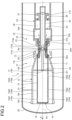
Fig. 1 is a sectional view of a gas circuit breaker according to an arrangement, which illustrates a connected state; -
Fig. 2 is a sectional view of the gas circuit breaker according to the arrangement, which illustrates an open state; -
Fig. 3 is a diagram illustrating an open state after the state ofFig. 2 ; -
Fig. 4 is a sectional view taken along line V-V inFig. 1 ; -
Fig. 5 is a sectional view taken along line VI-VI inFig. 1 ; -
Fig. 6 is a diagram illustrating an example of a structure of a gas circuit breaker according to a second arrangement; -
Fig. 7 is a sectional view taken along line VII-VII inFig. 6 ; -
Fig. 8 is a diagram illustrating an example of a structure of gas chambers divided into four in a circumferential direction; and -
Fig. 9 is a chart illustrating a time history of temperatures in the vicinity of an opposing arc contact. - Hereinafter, exemplary arrangements of the present application will be disclosed. The structures and control (technical features) of the arrangements described below as well as the actions and results (effects) brought about by such structures and control are examples. Furthermore, plural arrangements illustrated below include similar structural components. Hereafter, common reference signs are applied to similar structural components, and duplicate explanations will be omitted.
- In order to effectively cool arc discharge, it is necessary to significantly increase the pressure in a puffer chamber that is a pressure accumulation space, and increase an exhaust flow rate of a gas stream. The pressure increase in the puffer chamber acts as a driving reaction force when the pressure acting on a puffer piston drives it to open. A large driving force is required to significantly increase the pressure in the puffer chamber. In order to generate a large driving force, it is necessary to increase the size of a driving device. Furthermore, as the pressure in the puffer chamber increases, the weight of a movable contact including the puffer chamber increases for increasing the mechanical strength to withstand the pressure, causing the necessity to increase the drive energy further.
- Therefore, in recent years, a method for downsizing the puffer chamber and decreasing the reaction force and a method for accumulating the pressure in the puffer chamber using a hot arc-extinguishing gas that is heated by arc discharge have been developed.
- However, downsizing the puffer piston reduces the mass of the arc-extinguishing gas blown onto the arc discharge, which may cause problems such as a decrease in the gas density and an increase in the gas temperature. A decrease in the gas density leads to a decrease in the dynamic pressure.
- Furthermore, a sulfur hexafluoride gas or the like often used as an arc-extinguishing gas (insulating gas) causes a very high greenhouse effect, so that it is necessary to develop a gas circuit breaker that uses alternative gases. However, with alternative gases, due to the gas properties, the arc may not be cooled (insulated) sufficiently, thereby failing to interrupt an electric current. In addition, the flow may be separated at an insulating nozzle part where the cross-sectional area of the flow passage widens, and the hot gas stays therein without flowing downstream, thereby causing insulation breakdown.
- The gas circuit breaker according to the arrangements described below cools the arc more effectively and improves the current breaking performance over a wider breaking current area, even when alternative gases are used as the arc-extinguishing gas.
- As illustrated in
Fig. 1 to Fig. 3 , a gas circuit breaker 1 includes anopposing contact part 10 and amovable contact part 20 as two contact parts constituting an electric path. The gas circuit breaker 1 switches between a connected state (Fig. 1 ) where theopposing contact part 10 and themovable contact part 20 are in contact with each other, and an open state (Fig. 2 andFig. 3 ) where theopposing contact part 10 and themovable contact part 20 are separated from each other. In the open state after the connected state, an arc discharge occurs between theopposing contact part 10 and themovable contact part 20. By blowing a flow of an arc-extinguishing gas onto the arc discharge, the arc discharge is insulated, cooled, and extinguished at the current zero point, thereby interrupting the current. The connected state may also be referred to as a contact state, and the open state may also be referred to as a separated state. - As illustrated in
Fig. 1 , the gas circuit breaker 1 includes a sealedcontainer 30. The sealedcontainer 30 is filled with an arc-extinguishing gas. The sealedcontainer 30 is, for example, composed of a metal material, an insulator, or the like, and it is connected to ground. The sealedcontainer 30 is an example of a container. - The arc-extinguishing gas is, for example, a gas with excellent arc-extinguishing and insulation performance such as a sulfur hexafluoride gas (SF6 gas), air, carbon dioxide, oxygen, nitrogen, mixtures of those, or the like. Note that the arc-extinguishing gas may be, for example, a gas that has a lower global warming potential and lower molecular weight than the SF6 gas has, and is in a gas phase at least at 1 atmospheric pressure or higher and 20 degrees Celsius or lower.
- In the sealed
container 30, theopposing contact part 10 and themovable contact part 20 are disposed opposing to each other. Theopposing contact part 10 and themovable contact part 20 each have a plurality of members, such as cylindrical or columnar members, and are concentrically disposed with each other around a central axis Ax. In the following, "axial direction" is the axial direction of the central axis Ax, "radial direction" is the radial direction of the central axis Ax, and "circumferential direction" is the circumferential direction of the central axis Ax. Theopposing contact part 10 is an example of an opposing part, and themovable contact part 20 is an example of a movable part. Furthermore, in the following, theopposing contact part 10 side in the axial direction, that is, the left side inFig. 1 to Fig. 3 , is referred to as an axial direction A, and themovable contact part 20 side in the axial direction, that is, the right side inFig. 1 to Fig. 3 , is referred to as the other direction of the axial direction A, for convenience. Furthermore, since theopposing contact part 10 is fixed to the sealedcontainer 30 in the present arrangement, it may also be referred to as a fixed contact part. - From the inner face of the sealed
container 30, asupport member 31 protrudes inwardly in the radial direction. Theopposing contact part 10 is fixed to the sealedcontainer 30 via thesupport member 31. Thesupport member 31 insulates the sealedcontainer 30 and the opposingcontact part 10. Thus, thesupport member 31 may also be referred to as an insulating support member. - The
movable contact part 20 is connected to anoperation rod 40. Theoperation rod 40 is structured in a cylindrical shape extending along the axial direction A about the central axis Ax, and it is structured to be capable of reciprocating along the central axis Ax. Theoperation rod 40 is moved along the axial direction A by a drive device (not illustrated). Themovable contact part 20 moves in the axial direction A in conjunction with theoperation rod 40. When theoperation rod 40 moves in the direction approaching theopposing contact part 10, that is, in the axial direction A, theopposing contact part 10 and themovable contact part 20 come to be in the connected state, as illustrated inFig. 1 . When theoperation rod 40 moves in the direction away from theopposing contact part 10, that is, in the other direction of the axial direction A, theopposing contact part 10 and themovable contact part 20 come to be in an open state, as illustrated inFig. 2 andFig. 3 . Furthermore, theoperation rod 40 also functions as a discharge pipe for the arc-extinguishing gas. In other words, the arc-extinguishing gas can enter the cylinder of theoperation rod 40 from the end part in the axial direction A, pass through the cylinder, and flow out into the sealedcontainer 30 via anopening part 21b. - The
opposing contact part 10 includes anopposing arc contact 11 and an opposing current-carryingcontact 12. Furthermore, themovable contact part 20 includes amovable arc contact 21 and a movable current-carryingcontact 22. Theopposing arc contact 11 and themovable arc contact 21 oppose to each other in the axial direction A, and electrically connected in the connected state.
Furthermore, the opposing current-carryingcontact 12 and the movable current-carryingcontact 22 oppose to each other in the axial direction A, and are electrically connected in the connected state. When the opposingcontact part 10 is fixed to the sealedcontainer 30, the opposingarc contact 11 may also be referred to as a fixed arc contact, and the opposing current-carryingcontact 12 may also be referred to as a fixed current-carrying contact. - The opposing
arc contact 11 is a rod-shaped conductor, and extends along the axial direction A about the central axis Ax. Inside anexhaust stack 13 of the opposingcontact part 10, a disk-shapedfirst shield wall 14 orthogonal to the axial direction A is provided. Furthermore, from thefirst shield wall 14, asecond shield wall 15 extending along the axial direction A is provided toward the other direction of the axial direction A. - The
movable arc contact 21 is a tubular conductor, and extends along the axial direction A about the central axis Ax. In the present arrangement, as an example, themovable arc contact 21 is integrated with theoperation rod 40. At an end part of themovable arc contact 21 in the axial direction A, a circular through-hole 21a is provided. The end part where the through-hole 21a is provided is divided into a plurality of finger-shaped electrodes extending along the axial direction A by a plurality of slits (not illustrated) extending along the axial direction A. The end parts of the finger-shaped electrodes are aligned along an edge of a diameter that is smaller than the outer peripheral face of the opposingarc contact 11. Along with the move of theoperation rod 40, themovable arc contact 21 approaches the opposingarc contact 11, and the opposingarc contact 11 is inserted into the through-hole 21a, as illustrated inFig. 1 . Whereby, the finger-shaped electrodes are pushed by the outer peripheral face of the opposingarc contact 11 and spread outward in the radial direction to be in contact with the outer peripheral face of the opposingarc contact 11 by the elastic force of the finger-shaped electrodes. - The tip parts of the opposing
arc contact 11 and themovable arc contact 21 are covered by an insulatingnozzle 50 with a gap provided therebetween. The insulatingnozzle 50 is made of, for example, a heat-resistant and insulating material such as polytetrafluoroethylene. In the present arrangement, as an example, the insulatingnozzle 50 is fixed at the end part of themovable contact part 20 in the axial direction A, and moves in the axial direction A together with theoperation rod 40 and acylinder 23. The insulatingnozzle 50 has a cylindrical outer face, and extends along the axial direction A about the central axis Ax. The insulatingnozzle 50 is an example of a nozzle. - The insulating
nozzle 50 has anopening part 50a that is opened through in the axial direction A about the central axis Ax. As illustrated inFig. 1 , the opposingarc contact 11 can be inserted in amiddle part 50m of theopening part 50a in the axial direction A with a gap provided therebetween. Themiddle part 50m may also be referred to as a throat. Furthermore, as illustrated inFig. 2 andFig. 3 , themovable arc contact 21 is inserted between themiddle part 50m of theopening part 50a and athermal puffer chamber 25 with a gap provided therebetween. This gap constitutes apassage 50p of the arc-extinguishing gas between themiddle part 50m and thethermal puffer chamber 25. Furthermore, between themiddle part 50m and the end part of the insulatingnozzle 50 in the axial direction A, a conical face shaped diameter-enlarged part is formed with the diameter widened toward the end part.
As illustrated inFig. 3 , the diameter-enlarged part constitutes apassage 50s of the arc-extinguishing gas between themiddle part 50m and theexhaust stack 13. Theopening part 50a is an example of a space. - The opposing current-carrying
contact 12 is a tubular conductor, and extends along the axial direction A about the central axis Ax. The opposing current-carryingcontact 12 is joined at the outer peripheral face of the end part of theexhaust stack 13 in the other direction of the axial direction A. The opening edge of the opposing current-carryingcontact 12 in the longitudinal direction of the opposing current-carryingcontact 12 protrudes inwardly in the radial direction. - The movable current-carrying
contact 22 is a tubular conductor, and extends along the axial direction A about the central axis Ax. Themovable contact part 20 includes thecylinder 23 in a cylindrical shape that houses theoperation rod 40. The movable current-carryingcontact 22 is joined at the end part of thecylinder 23 in the axial direction A. Along with the move of theoperation rod 40, the movable current-carryingcontact 22 approaches the opposing current-carryingcontact 12 and inserted into the opposing current-carryingcontact 12, as illustrated inFig. 1 . The inner diameter of the opening edge of the opposing current-carryingcontact 12 and the outer diameter of the movable current-carryingcontact 22 are substantially the same, and the opposing current-carryingcontact 12 and the movable current-carryingcontact 22 are electrically connected in a state where the movable current-carryingcontact 22 is being inserted into the opposing current-carryingcontact 12. - In the structure described above, in the open state after the connected state, as illustrated in
Fig. 2 andFig. 3 , an arc discharge Ad occurs between the opposingarc contact 11 and themovable arc contact 21 inside theopening part 50a of the insulatingnozzle 50. The generated arc discharge Ad is extinguished by a flow of the arc-extinguishing gas. Hereafter, the flow of the arc-extinguishing gas may also be referred to simply as a gas flow. - The gas flow is generated in the
cylinder 23. Thecylinder 23 is a tubular conductor, and extends along the axial direction A about the central axis Ax. Thecylinder 23 is fixed to theoperation rod 40. In other words, along with the move of theoperation rod 40, thecylinder 23 also moves. - Between the
cylinder 23 and theoperation rod 40, an annular space is provided. The annular space is partitioned in the axial direction A by apartition wall 24 extending in the radial direction, thereby forming thethermal puffer chamber 25 and amechanical puffer chamber 26. The gas flow that is blown onto the arc discharge Ad is generated in thethermal puffer chamber 25 and themechanical puffer chamber 26. Thepartition wall 24 has a plurality of through-holes 24a provided therein. The arc-extinguishing gas can travel back and forth between thethermal puffer chamber 25 and themechanical puffer chamber 26 via the throughholes 24a. Thethermal puffer chamber 25 and themechanical puffer chamber 26 are examples of a pressure accumulation part, which may also be referred to as a pressure accumulation space. - In the
thermal puffer chamber 25, the pressure of the arc-extinguishing gas is increased by the thermal energy generated by the arc discharge Ad between the opposingarc contact 11 and themovable arc contact 21 as illustrated inFig. 2 . Specifically, as indicated by arrows inFig. 2 , the pressure wave generated by the thermal energy of the arc discharge Ad is introduced into thethermal puffer chamber 25, thereby increasing the pressure in thethermal puffer chamber 25. - In the
mechanical puffer chamber 26, on the opposite side of thepartition wall 24, apiston 27 fixed to the sealedcontainer 30 is disposed. Thepiston 27 is housed in thecylinder 23 to be relatively slidable with thecylinder 23 and theoperation rod 40 in the axial direction A. As is clear by comparingFig. 2 andFig. 3 withFig. 1 , when thecylinder 23 and theoperation rod 40 move in the other direction of the axial direction A, the distance between thepartition wall 24 and thepiston 27 is shortened and the volume of themechanical puffer chamber 26 becomes smaller. This reduction in the volume of themechanical puffer chamber 26 increases the pressure of the arc-extinguishing gas in themechanical puffer chamber 26. Note that thepiston 27 has arelief valve 28 that opens with a pressure of a prescribed value or more. Therelief valve 28 suppresses the pressure in themechanical puffer chamber 26 from rising to a prescribed value or more. - As illustrated in
Fig. 2 , when the arc discharge Ad occurs between the opposingarc contact 11 and themovable arc contact 21, a pressure wave of the arc-extinguishing gas is introduced into thethermal puffer chamber 25 via thepassage 50p of the insulatingnozzle 50, thereby increasing the pressure in thethermal puffer chamber 25. Furthermore, the pressure in themechanical puffer chamber 26 increases in accordance with the relative move of thecylinder 23, theoperation rod 40, and thepiston 27, as described above. As illustrated inFig. 3 , in accordance with the pressure increase, the arc-extinguishing gas in themechanical puffer chamber 26 flows into thethermal puffer chamber 25 via the through-holes 24a and, together with the arc-extinguishing gas in thethermal puffer chamber 25, acts on the arc discharge Ad via thepassage 50p in the insulatingnozzle 50 to extinguish the arc discharge Ad. - The
exhaust stack 13 includes acylindrical part 13a and aconical part 13b. Thecylindrical part 13a is positioned on the axial direction A side of theexhaust stack 13. Furthermore, theconical part 13b is positioned on the side in the other direction of the axial direction A of theexhaust stack 13. Theconical part 13b is structured to be gradually tapered from thecylindrical part 13a toward anend part 13c on themovable contact part 20 side. Theconical part 13b may also be referred to as a diffuser. - As illustrated in
Fig. 1 to Fig. 3 , ashield part 19 is provided inside theexhaust stack 13. Theshield part 19 includes thefirst shield wall 14 and thesecond shield wall 15. Thefirst shield wall 14 is structured in a disk shape orthogonal to the axial direction A. Thefirst shield wall 14 may also be referred to as a shield plate. - The
second shield wall 15 is structured in a cylindrical shape extending along the axial direction A about the central axis Ax. Thesecond shield wall 15 extends from the end part of thefirst shield wall 14 on the outward side of the radial direction toward theend part 13c of theexhaust stack 13 in the other direction of the axial direction A. Thesecond shield wall 15 is in contact with theend part 13c, that is, the opening edge, of theexhaust stack 13. In other words, the space between thesecond shield wall 15 and theconical part 13b is almost closed by theend part 13c. Thesecond shield wall 15 may be in a tubular shape other than a cylindrical shape, such as a tubular shape with a polygonal cross section or the like, for example. Thesecond shield wall 15 may also be referred to as a shield cylinder. - The
second shield wall 15 has through-holes 15a provided therein. More specifically, in thesecond shield wall 15, a plurality of through-holes 15a is provided at an interval along the axial direction A. Those through-holes 15a constitute a row along the axial direction A. In the present arrangement, a plurality of rows constituted with the through-holes 15a are provided at an interval in the circumferential direction of theexhaust stack 13. In the present arrangement, as an example, three through-holes 15a (through-holes 15a1, 15a2, 15a3) are provided along the axial direction A in each row. - As is clear from
Fig. 1 to Fig. 3 , the insulatingnozzle 50 is inserted into thesecond shield wall 15 and moves along the axial direction A inside thesecond shield wall 15. Furthermore, a relatively narrow clearance is provided between the inner face of thesecond shield wall 15 and the outer face of the insulatingnozzle 50. This prevents leakage of the arc-extinguishing gas from the gap between thesecond shield wall 15 and the insulatingnozzle 50. The inner face of thesecond shield wall 15 is an example of a guide part that guides the insulatingnozzle 50. - The
second shield wall 15 has the through-holes 15a provided therein. Via the through-holes 15a, the space inside thesecond shield wall 15 and the space outside thesecond shield wall 15 are connected. - Thus, as illustrated in
Fig. 3 , in theexhaust stack 13, the arc-extinguishing gas from the insulatingnozzle 50 flows out from the space inside thesecond shield wall 15 to the space outside thesecond shield wall 15 via a gap G2 and the through-holes 15a. Furthermore, the arc-extinguishing gas flows into the space inside thecylindrical part 13a and flows out from anend part 13d of theexhaust stack 13 into the sealedcontainer 30. At this time, the pressure in thethermal puffer chamber 25 and the mechanical puffer chamber 26 (pressure accumulation part) is higher than the pressure in the insulatingnozzle 50, and the pressure in the insulatingnozzle 50 is higher than the pressure in theexhaust stack 13. - Furthermore, at this time, the arc-extinguishing gas flowed into the
second shield wall 15 passes between the opposingarc contact 11 and thesecond shield wall 15 at supersonic speeds. More specifically, in the present arrangement, the arc-extinguishing gas passes between astructure 18 and thesecond shield wall 15 at supersonic speeds. The arc-extinguishing gas then becomes subsonic inside thesecond shield wall 15 after passing between thestructure 18 including the opposingarc contact 11 and thesecond shield wall 15. This is because, in the area inside thesecond shield wall 15 in the axial direction A, the cross-sectional area of the space that serves as the passage for the arc-extinguishing gas increases more rapidly in the area where thestructure 18 is not provided than in the area where thestructure 18 is provided. As a result, a shock wave is generated, thereby decelerating the speeds to subsonic speeds. The arc-extinguishing gas, which has become subsonic, then flows into the through-holes 15a. InFig. 3 , the arc-extinguishing gas flows at supersonic speeds on the right side of a dashed line B, and flows at subsonic speeds on the left side of the dashed line B. As described above, the shield part 19 (thefirst shield wall 14 and the second shield wall 15) allows the flow of the arc-extinguishing gas in theexhaust stack 13 via the gaps G1, G2 and the through-holes 15a. The gaps G1, G2 and the through-holes 15a are passages for the arc-extinguishing gas. Note that the gap G1 can also be considered an opening part provided in the structure including a support member 16, thesecond shield wall 15, and theexhaust stack 13. Furthermore, the gap G2 can also be considered an opening part provided in the structure including asupport member 17 and thesecond shield wall 15. - In the present arrangement, in order to cool the arc more effectively, a jet hole that ejects the arc-extinguishing gas against the arc discharge Ad is provided. For example, as illustrated in
Fig. 1 to Fig. 3 , the insulatingnozzle 50 is provided with one ormore jet holes 111a, one ormore flow passages 112a, and one ormore inflow holes 113a. - The
inflow hole 113a is an example of a hole through which part of the arc-extinguishing gas flowing in thepassage 50p flows in. Thepassage 50p corresponds to a flow passage (first flow passage) of the arc-extinguishing gas between themiddle part 50m (an example of a middle part) and thethermal puffer chamber 25. - The
jet hole 111a is a hole for ejecting an unsteady jet flow of the arc-extinguishing gas against the arc discharge Ad. Thejet hole 111a may be provided at any positions in the insulatingnozzle 50, for example, in themiddle part 50m where the cross-sectional area of the flow passage is constant, or in the diameter-enlarged part. The positions of thejet holes 111a may be determined, for example, as the positions where the arc-extinguishing gas is ejected at the timing where the arc discharge Ad can be more efficiently extinguished during the period of an open state. Furthermore, the size of thejet holes 111a may be the size to be able to eject the arc-extinguishing gas as a jet flow. For example, thejet holes 111a are in a size at least smaller than the cross-sectional area of thepassage 50p. - The
flow passage 112a is a flow passage (jet-forming flow passage) for forming a jet flow ejected from thejet hole 111a. Theflow passage 112a is an example of a flow passage (second flow passage) through which part of the arc-extinguishing gas flowing in from thepassage 50p flows. - With such a structure, the arc-extinguishing gas whose pressure is increased in the pressure accumulation part flows into the
opening part 50a via thepassage 50p, and it is ejected from thejet holes 111a through theflow passages 112a toward the arc discharge Ad, thereby extinguishing the arc discharge Ad. - At least one of the one or
more jet holes 111a is provided to be able to eject a jet flow of the arc-extinguishing gas against the arc discharge Ad. This creates a flow of the arc-extinguishing gas toward the center of the arc discharge Ad, and vortexes around various axes different from the central axis Ax. As a result, heat transfer is promoted, so that the arc discharge Ad can be cooled more effectively. The jet flow can also eliminate stagnation of the hot insulating gas associated with flow separation that may occur in areas of the insulatingnozzle 50 where the cross-sectional area of the flow passage gradually expands. -
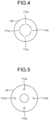
Fig. 4 is a sectional view taken along line V-V inFig. 1 .Fig. 5 is a sectional view taken along line VI-VI inFig. 1 .Fig. 4 and Fig. 5 correspond to cross sections orthogonal to the axial direction A in the areas where thejet holes 111a and theflow passages 112a are provided, respectively.Fig. 4 and Fig. 5 illustrate examples where the fourjet holes 111a and the fourflow passages 112a are provided in an axially symmetrical manner about the central axis Ax, respectively. - The structures in
Fig. 4 and Fig. 5 are examples only, and the structures are not limited thereto. As for thejet holes 111a and theflow passages 112a, one of each simply need to be provided. When a plurality ofjet holes 111a and a plurality offlow passages 112a are provided, thejet holes 111a and theflow passages 112a do not need to be axially symmetric about the central axis Ax. - There is no need for the
jet hole 111a and theflow passage 112a (inflow hole 113a) to correspond to each other on a one-to-one basis. For example, theflow passage 112a may be formed such that the arc-extinguishing gas flowed in from asingle inflow hole 113a is ejected from a plurality ofjet holes 111a. Furthermore, theflow passage 112a may be formed such that the arc-extinguishing gas flowed in from a plurality ofinflow holes 113a is ejected from asingle jet hole 111a. - When a plurality of
inflow holes 113a is provided, each of theinflow holes 113a does not need to be provided at the same position in the axial direction. Similarly, when a plurality ofjet holes 111a is provided, each of thejet holes 111a does not need to be provided at the same position in the axial direction. For example, some of thejet holes 111a may be provided in themiddle part 50m, while the rest of thejet holes 111a may be provided in the diameter-enlarged part. This allows the arc-extinguishing gas to be ejected against the arc discharge Ad at more timings included in the period of the open state. - When a plurality of
inflow holes 113a is provided, theinflow holes 113a may be in different sizes from each other. When a plurality ofjet holes 111a is provided, thejet holes 111a may be in different sizes from each other. When a plurality offlow passages 112a is provided, theflow passages 112a may have different cross-sectional areas from each other. - As described, the first arrangement includes the
jet holes 111a, so that it is possible to cool the arc more effectively and improve the current breaking performance over a wider breaking current area, even when alternative gases are used as the arc-extinguishing gas. - A gas circuit breaker according to a second arrangement includes a gas chamber instead of the
flow passage 112a of the first arrangement. The gas chamber corresponds to a housing part into which part of the arc-extinguishing gas flowing in thepassage 50p flows, the housing part housing the arc-extinguishing gas flowed therein, and ejecting the housed arc-extinguishing gas from one or more jet holes. -
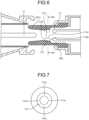
Fig. 6 is a diagram illustrating an example of the structure of the gas circuit breaker according to the second arrangement. In the second arrangement, the structure of an insulating nozzle 50-2 is different from that of the insulatingnozzle 50 of the first arrangement. Other structural components are the same as those of the first arrangement, so that illustration thereof are omitted inFig. 6 or the same reference signs are given thereto. Explanation of the structural components to which the same reference signs are given is omitted. - The insulating nozzle 50-2 includes one or
more jet holes more gas chambers 121, and one ormore inflow holes 113a. In the example ofFig. 6 , thegas chamber 121 is structured to house the arc-extinguishing gas flowing in from theinflow hole 113a and to eject the housed arc-extinguishing gas from the threejet holes -
Fig. 7 is a sectional view taken along line VII-VII inFig. 6. Fig. 7 corresponds to a cross section orthogonal to the axial direction A in the area where thejet holes 111d are provided.Fig. 7 illustrates an example of asingle gas chamber 121 that is not divided in the circumferential direction. In other words, in the example ofFig. 7 , the insulating nozzle 50-2 includes asingle gas chamber 121. Furthermore,Fig. 7 illustrates an example where the fourjet holes 111d are provided in an axially symmetrical manner about the central axis Ax. The insulating nozzle 50-2 may include, for example, fourinflow holes 113a, fourjet holes 111b, and fourjet holes 111c, which are provided in an axially symmetrical manner by corresponding to the fourjet holes 111d, respectively. - The
gas chamber 121 houses the arc-extinguishing gas flowing in from the fourinflow holes 113a, for example, and ejects the housed arc-extinguishing gas from 4x3 jet holes (jet holes - The structure of the
gas chamber 121 is not limited to that illustrated inFig. 7 . For example, a plurality ofgas chambers 121 divided in the circumferential direction may be provided.Fig. 8 is a diagram illustrating an example of the structure of thegas chambers 121 divided into four in the circumferential direction. - Each of the four
gas chambers 121 corresponds to any one of the fourinflow holes 113a, any one of the fourjet holes 111b, and any one of the fourjet holes 111c, for example. Then, each of the fourgas chambers 121 houses the arc-extinguishing gas flowing in from the correspondinginflow hole 113a, and ejects the housed arc-extinguishing gas from the corresponding three jet holes (jet holes - Next, current interruption according to the above described arrangements (first arrangement and second arrangement) will be described.
Fig. 9 is a chart illustrating a time history of the temperatures in the vicinity of the opposingarc contact 11. The horizontal axis inFig. 9 represents time (elapsed time), and the vertical axis represents the temperature in the vicinity of the opposingarc contact 11. FromFig. 9 , it can be seen that the temperature drops rapidly from the high temperature state caused by the arc discharge Ad, by blowing the arc-extinguishing gas onto the arc discharge Ad and letting it flow out into the sealedcontainer 30. As a result, the current is interrupted. - Note that the jet holes simply need to be able to eject an unsteady jet flow of the arc-extinguishing gas from the insulating nozzle toward the arc discharge, and are not limited to the jet holes of the above arrangements (first arrangement and second arrangement).
- While certain arrangements have been described, these arrangements have been presented by way of example only, and are not intended to limit the scope of the claims. Indeed, the apparatuses described herein may be embodied in a variety of other forms; furthermore various omissions, substitutions and changes in the form of the apparatuses described herein may be made.
- Example 1. A gas circuit breaker (1) according to an arrangement includes a container (30), an opposing part, a movable part, and a nozzle (50). The container (30) is filled with an arc-extinguishing gas. The opposing part is housed in the container (30). The opposing part includes an opposing arc contact (11) and an exhaust stack. The movable part is housed in the container (30). The movable part includes a movable arc contact (21) that comes in contact with the opposing arc contact (11) in a connected state, and separates from the opposing arc contact (11) in an open state; and a pressure accumulation part where a pressure of the arc-extinguishing gas is increased.
The nozzle (50) is housed in the container (30) and includes a space where arc discharge occurs between the movable arc contact (21) and the opposing arc contact (11). The nozzle (50) includes a middle part (50m) where the opposing arc contact (11) is inserted, and includes one or more jet holes (111a, 111b, 111c, 111d) that eject, toward the space, part of the arc-extinguishing gas flowing in from a first flow passage between the pressure accumulation part and the middle part (50m). The arc-extinguishing gas whose pressure is increased in the pressure accumulation part flows into the space via the first flow passage and the jet holes (111a, 111b, 111c, 111d) to extinguish the arc discharge. - Example 2. In the gas circuit breaker (1) according to example 1, the nozzle (50) includes one or more second flow passages where part of the arc-extinguishing gas flowing in the first flow passage flows in. The one or more second flow passages allow inflow arc-extinguishing gas to flow out to the one or more jet holes (111a, 111b, 111c, 111d).
- Example 3. In the gas circuit breaker (1) according to example 1, the nozzle (50) includes a housing part where part of the arc-extinguishing gas flowing in the first flow passage flows in. The housing part houses inflow arc-extinguishing gas and ejects the housed arc-extinguishing gas from the one or more jet holes (111a, 111b, 111c, 111d).
- Example 4. In the gas circuit breaker (1) according to example 1, the nozzle (50) includes one or more inflow holes where part of the arc-extinguishing gas flowing in the first flow passage flows in, and each of the one or more jet holes (111a, 111b, 111c, 111d) ejects, toward the space, the arc-extinguishing gas flowed in from any of the one or more inflow holes.
- Example 5. In the gas circuit breaker (1) according to example 1, the nozzle (50) includes a diameter-enlarged part with a diameter expanding from the middle part (50m) toward an end part on a side of the opposing arc contact (11), and each of the one or more jet holes (111a, 111b, 111c, 111d) is provided in the middle part (50m) or the diameter-enlarged part.
- Example 6. In the gas circuit breaker (1) according to example 1, the arc-extinguishing gas is a gas that has a lower global warming potential than a sulfur hexafluoride gas has, that has a lower molecular weight than the sulfur hexafluoride gas has, and that is in a gas phase at least at 1 atmospheric pressure or higher and 20 degrees Celsius or lower.
Claims (6)
- A gas circuit breaker (1), comprising:a container (30) filled with an arc-extinguishing gas;an opposing part that is housed in the container (30), the opposing part including an opposing arc contact (11) and an exhaust stack;a movable part that is housed in the container (30), the movable part including: a movable arc contact (21) that comes in contact with the opposing arc contact (11) in a connected state, and separates from the opposing arc contact (11) in an open state; and a pressure accumulation part where a pressure of the arc-extinguishing gas is increased; anda nozzle (50) that is housed in the container (30), the nozzle (50) including a space where arc discharge occurs between the movable arc contact (21) and the opposing arc contact (11), whereinthe nozzle (50) comprises:a middle part (50m) where the opposing arc contact (11) is inserted, andone or more jet holes (111a, 111b, 111c, 111d) that eject, toward the space, part of the arc-extinguishing gas flowing in from a first flow passage between the pressure accumulation part and the middle part (50m), andthe arc-extinguishing gas whose pressure is increased in the pressure accumulation part flows into the space via the first flow passage and the jet holes (111a, 111b, 111c, 111d) to extinguish the arc discharge.
- The gas circuit breaker (1) according to claim 1, wherein the nozzle (50) comprises one or more second flow passages where part of the arc-extinguishing gas flowing in the first flow passage flows in, the one or more second flow passages allowing inflow arc-extinguishing gas to flow out to the one or more jet holes (111a, 111b, 111c, 111d).
- The gas circuit breaker (1) according to claim 1, wherein the nozzle (50) comprises a housing part where part of the arc-extinguishing gas flowing in the first flow passage flows in, the housing part housing inflow arc-extinguishing gas and ejecting the housed arc-extinguishing gas from the one or more jet holes (111a, 111b, 111c, 111d) .
- The gas circuit breaker (1) according to claim 1,
whereinthe nozzle (50) includes one or more inflow holes where part of the arc-extinguishing gas flowing in the first flow passage flows in, andeach of the one or more jet holes (111a, 111b, 111c, 111d) ejects, toward the space, the arc-extinguishing gas flowed in from any of the one or more inflow holes. - The gas circuit breaker (1) according to claim 1,
whereinthe nozzle (50) includes a diameter-enlarged part with a diameter expanding from the middle part (50m) toward an end part on a side of the opposing arc contact (11), andeach of the one or more jet holes (111a, 111b, 111c, 111d) is provided in the middle part (50m) or the diameter-enlarged part. - The gas circuit breaker (1) according to claim 1,
wherein the arc-extinguishing gas is a gas thathas a lower global warming potential than a sulfur hexafluoride gas has,has a lower molecular weight than the sulfur hexafluoride gas has, andis in a gas phase at least at 1 atmospheric pressure or higher and 20 degrees Celsius or lower.
Applications Claiming Priority (1)
| Application Number | Priority Date | Filing Date | Title |
|---|---|---|---|
| JP2023032440A JP2024124633A (en) | 2023-03-03 | 2023-03-03 | Gas Circuit Breaker |
Publications (1)
| Publication Number | Publication Date |
|---|---|
| EP4425518A1 true EP4425518A1 (en) | 2024-09-04 |
Family
ID=87863152
Family Applications (1)
| Application Number | Title | Priority Date | Filing Date |
|---|---|---|---|
| EP23193868.9A Pending EP4425518A1 (en) | 2023-03-03 | 2023-08-29 | Gas circuit breaker |
Country Status (4)
| Country | Link |
|---|---|
| US (1) | US20240297005A1 (en) |
| EP (1) | EP4425518A1 (en) |
| JP (1) | JP2024124633A (en) |
| CN (1) | CN118588486A (en) |
Families Citing this family (1)
| Publication number | Priority date | Publication date | Assignee | Title |
|---|---|---|---|---|
| CN120177840A (en) * | 2025-05-22 | 2025-06-20 | 安徽徽电科技股份有限公司 | High voltage AC withstand voltage test device and method for high voltage equipment using capacitive voltage divider |
Citations (4)
| Publication number | Priority date | Publication date | Assignee | Title |
|---|---|---|---|---|
| US5723840A (en) * | 1995-05-04 | 1998-03-03 | Ansaldo Industria S.P.A. | Gas-dielectric high-tension interrupter of the arc-puffer type |
| JPH1186697A (en) * | 1997-09-08 | 1999-03-30 | Mitsubishi Electric Corp | Puffer type gas circuit breaker for DC |
| JP2004039312A (en) * | 2002-06-28 | 2004-02-05 | Toshiba Corp | Switch |
| WO2018225255A1 (en) * | 2017-06-09 | 2018-12-13 | 株式会社 東芝 | Gas circuit breaker |
Family Cites Families (13)
| Publication number | Priority date | Publication date | Assignee | Title |
|---|---|---|---|---|
| DE2057686A1 (en) * | 1969-11-27 | 1971-06-03 | Magrini Fab Riun Scarpa | Improved blower opening unit for a self-extinguishing electrical pressure gas switch |
| DE2455674A1 (en) * | 1974-11-25 | 1976-05-26 | Siemens Ag | ARRANGEMENT FOR EXTINGUISHING AN ARC IN A GAS FLOW SWITCH |
| DE19547522C1 (en) * | 1995-12-08 | 1997-01-16 | Siemens Ag | HV line circuit breaker with gas-storage space - has gas-storage space divided by partition into heating space and cold gas space |
| FR2821482B1 (en) * | 2001-02-27 | 2003-04-04 | Alstom | CIRCUIT BREAKER INCLUDING A PISTON COMPRESSION CHAMBER DRAIN CHANNEL |
| DE502007006438D1 (en) * | 2007-10-16 | 2011-03-17 | Abb Research Ltd | A RELIEF CHANNEL CONTROLLED BY AN OVERFLOW VALVE |
| CN102714112B (en) * | 2010-02-04 | 2016-01-27 | 三菱电机株式会社 | Gas-break switch |
| DE102010020979A1 (en) * | 2010-05-12 | 2011-11-17 | Siemens Aktiengesellschaft | Compressed gas circuit breakers |
| CN103703533B (en) * | 2011-08-30 | 2016-04-20 | 三菱电机株式会社 | gas circuit breaker |
| CN102945768B (en) * | 2012-11-07 | 2015-04-22 | 中国西电电气股份有限公司 | Arc-control device of breaker |
| EP3149757B1 (en) * | 2014-06-02 | 2018-08-08 | ABB Schweiz AG | High voltage puffer breaker and a circuit breaker unit comprising such a puffer breaker |
| JP6794327B2 (en) * | 2017-09-15 | 2020-12-02 | 株式会社東芝 | Gas circuit breaker |
| JP6961105B2 (en) * | 2018-10-24 | 2021-11-05 | 三菱電機株式会社 | Gas circuit breaker |
| JP7228714B2 (en) * | 2019-11-22 | 2023-02-24 | 株式会社東芝 | gas insulated equipment |
-
2023
- 2023-03-03 JP JP2023032440A patent/JP2024124633A/en active Pending
- 2023-08-23 CN CN202311063397.4A patent/CN118588486A/en active Pending
- 2023-08-24 US US18/455,065 patent/US20240297005A1/en active Pending
- 2023-08-29 EP EP23193868.9A patent/EP4425518A1/en active Pending
Patent Citations (4)
| Publication number | Priority date | Publication date | Assignee | Title |
|---|---|---|---|---|
| US5723840A (en) * | 1995-05-04 | 1998-03-03 | Ansaldo Industria S.P.A. | Gas-dielectric high-tension interrupter of the arc-puffer type |
| JPH1186697A (en) * | 1997-09-08 | 1999-03-30 | Mitsubishi Electric Corp | Puffer type gas circuit breaker for DC |
| JP2004039312A (en) * | 2002-06-28 | 2004-02-05 | Toshiba Corp | Switch |
| WO2018225255A1 (en) * | 2017-06-09 | 2018-12-13 | 株式会社 東芝 | Gas circuit breaker |
Also Published As
| Publication number | Publication date |
|---|---|
| CN118588486A (en) | 2024-09-03 |
| US20240297005A1 (en) | 2024-09-05 |
| JP2024124633A (en) | 2024-09-13 |
Similar Documents
| Publication | Publication Date | Title |
|---|---|---|
| US10964498B2 (en) | Gas-insulated low- or medium-voltage load break switch | |
| US9761395B2 (en) | Gas circuit breaker | |
| US20240297005A1 (en) | Gas circuit breaker | |
| JP2012069348A (en) | Gas circuit breaker | |
| US4080521A (en) | Quenching contact arrangement for a compressed-gas circuit breaker | |
| JP6139299B2 (en) | Gas circuit breaker | |
| US10475607B2 (en) | Gas circuit breaker | |
| WO2019150655A1 (en) | Gas circuit breaker | |
| WO2018225255A1 (en) | Gas circuit breaker | |
| JP2019091590A (en) | Gas-blast circuit breaker | |
| JP2018113189A (en) | Gas circuit breaker | |
| JP2015170544A (en) | Gas circuit breaker | |
| JP7612893B2 (en) | Gas Circuit Breaker | |
| WO2015129273A1 (en) | Gas circuit breaker | |
| JP2016143473A (en) | Gas circuit breaker | |
| JP2016143499A (en) | Gas circuit breaker | |
| CN111357074B (en) | Gas circuit breaker | |
| WO2023135639A1 (en) | Gas circuit breaker | |
| EP3433869B1 (en) | Electrical circuit breaker device | |
| WO2022070397A1 (en) | Gas circuit breaker | |
| JP2015023006A (en) | Gas circuit breaker | |
| JP2016062650A (en) | Gas circuit breaker | |
| JP6746787B2 (en) | Gas circuit breaker | |
| CN111433878B (en) | Gas circuit breaker | |
| JP2014186796A (en) | Gas circuit breaker |
Legal Events
| Date | Code | Title | Description |
|---|---|---|---|
| PUAI | Public reference made under article 153(3) epc to a published international application that has entered the european phase |
Free format text: ORIGINAL CODE: 0009012 |
|
| STAA | Information on the status of an ep patent application or granted ep patent |
Free format text: STATUS: REQUEST FOR EXAMINATION WAS MADE |
|
| 17P | Request for examination filed |
Effective date: 20230829 |
|
| AK | Designated contracting states |
Kind code of ref document: A1 Designated state(s): AL AT BE BG CH CY CZ DE DK EE ES FI FR GB GR HR HU IE IS IT LI LT LU LV MC ME MK MT NL NO PL PT RO RS SE SI SK SM TR |