EP4425293A1 - Verfahren zur wegplanung für einen mobilen nichtkreisförmigen roboter - Google Patents
Verfahren zur wegplanung für einen mobilen nichtkreisförmigen roboter Download PDFInfo
- Publication number
- EP4425293A1 EP4425293A1 EP23165592.9A EP23165592A EP4425293A1 EP 4425293 A1 EP4425293 A1 EP 4425293A1 EP 23165592 A EP23165592 A EP 23165592A EP 4425293 A1 EP4425293 A1 EP 4425293A1
- Authority
- EP
- European Patent Office
- Prior art keywords
- robot
- costmap
- mobile non
- circular
- circular robot
- Prior art date
- Legal status (The legal status is an assumption and is not a legal conclusion. Google has not performed a legal analysis and makes no representation as to the accuracy of the status listed.)
- Pending
Links
Images






Classifications
-
- B—PERFORMING OPERATIONS; TRANSPORTING
- B25—HAND TOOLS; PORTABLE POWER-DRIVEN TOOLS; MANIPULATORS
- B25J—MANIPULATORS; CHAMBERS PROVIDED WITH MANIPULATION DEVICES
- B25J9/00—Program-controlled manipulators
- B25J9/16—Program controls
- B25J9/1656—Program controls characterised by programming, planning systems for manipulators
- B25J9/1664—Program controls characterised by programming, planning systems for manipulators characterised by motion, path, trajectory planning
- B25J9/1666—Avoiding collision or forbidden zones
-
- G—PHYSICS
- G01—MEASURING; TESTING
- G01C—MEASURING DISTANCES, LEVELS OR BEARINGS; SURVEYING; NAVIGATION; GYROSCOPIC INSTRUMENTS; PHOTOGRAMMETRY OR VIDEOGRAMMETRY
- G01C21/00—Navigation; Navigational instruments not provided for in groups G01C1/00 - G01C19/00
- G01C21/26—Navigation; Navigational instruments not provided for in groups G01C1/00 - G01C19/00 specially adapted for navigation in a road network
- G01C21/34—Route searching; Route guidance
- G01C21/3407—Route searching; Route guidance specially adapted for specific applications
-
- G—PHYSICS
- G01—MEASURING; TESTING
- G01C—MEASURING DISTANCES, LEVELS OR BEARINGS; SURVEYING; NAVIGATION; GYROSCOPIC INSTRUMENTS; PHOTOGRAMMETRY OR VIDEOGRAMMETRY
- G01C21/00—Navigation; Navigational instruments not provided for in groups G01C1/00 - G01C19/00
- G01C21/20—Instruments for performing navigational calculations
-
- B—PERFORMING OPERATIONS; TRANSPORTING
- B25—HAND TOOLS; PORTABLE POWER-DRIVEN TOOLS; MANIPULATORS
- B25J—MANIPULATORS; CHAMBERS PROVIDED WITH MANIPULATION DEVICES
- B25J5/00—Manipulators mounted on wheels or on carriages
- B25J5/007—Manipulators mounted on wheels or on carriages mounted on wheels
-
- B—PERFORMING OPERATIONS; TRANSPORTING
- B25—HAND TOOLS; PORTABLE POWER-DRIVEN TOOLS; MANIPULATORS
- B25J—MANIPULATORS; CHAMBERS PROVIDED WITH MANIPULATION DEVICES
- B25J9/00—Program-controlled manipulators
- B25J9/16—Program controls
- B25J9/1628—Program controls characterised by the control loop
- B25J9/1653—Program controls characterised by the control loop parameters identification, estimation, stiffness, accuracy, error analysis
-
- G—PHYSICS
- G05—CONTROLLING; REGULATING
- G05D—SYSTEMS FOR CONTROLLING OR REGULATING NON-ELECTRIC VARIABLES
- G05D1/00—Control of position, course, altitude or attitude of land, water, air or space vehicles, e.g. using automatic pilots
- G05D1/20—Control system inputs
- G05D1/24—Arrangements for determining position or orientation
- G05D1/246—Arrangements for determining position or orientation using environment maps, e.g. simultaneous localisation and mapping [SLAM]
- G05D1/2464—Arrangements for determining position or orientation using environment maps, e.g. simultaneous localisation and mapping [SLAM] using an occupancy grid
-
- G—PHYSICS
- G05—CONTROLLING; REGULATING
- G05D—SYSTEMS FOR CONTROLLING OR REGULATING NON-ELECTRIC VARIABLES
- G05D1/00—Control of position, course, altitude or attitude of land, water, air or space vehicles, e.g. using automatic pilots
- G05D1/60—Intended control result
- G05D1/617—Safety or protection, e.g. defining protection zones around obstacles or avoiding hazards
- G05D1/622—Obstacle avoidance
- G05D1/628—Obstacle avoidance following the obstacle profile, e.g. a wall or undulated terrain
-
- G—PHYSICS
- G05—CONTROLLING; REGULATING
- G05D—SYSTEMS FOR CONTROLLING OR REGULATING NON-ELECTRIC VARIABLES
- G05D1/00—Control of position, course, altitude or attitude of land, water, air or space vehicles, e.g. using automatic pilots
- G05D1/60—Intended control result
- G05D1/644—Optimisation of travel parameters, e.g. of energy consumption, journey time or distance
-
- G—PHYSICS
- G05—CONTROLLING; REGULATING
- G05D—SYSTEMS FOR CONTROLLING OR REGULATING NON-ELECTRIC VARIABLES
- G05D2109/00—Types of controlled vehicles
- G05D2109/10—Land vehicles
- G05D2109/18—Holonomic vehicles, e.g. with omni wheels
Definitions
- the present invention relates to path control for navigation of a mobile robot.
- the invention refers to a method of path planning for a mobile non-circular robot in an environment with obstacles, like furniture, laboratory equipment, walls, desks, and the like, and further refers to a computing device for such path planning, for a system and a computer program product.
- an environment representation in the form of an x-y grid map is used, each cell (and/or node) of which is associated with a cost value that indexes obstacles in the immediate vicinity.
- [3] introduces collision-free orientation intervals for each x-y position, with the graph search traversing along intersecting intervals.
- [7] proposes efficient methods of partially updating changed sections of the map.
- a short planning time and more generally for saving resources during the planning, for a path of a mobile non-circular robot in an environment with obstacles.
- a (in particular computer-implemented) method of path planning for a mobile non-circular robot in an environment comprising obstacles comprises a step of receiving a three-dimensional (3D) costmap.
- the 3D costmap comprises a two-dimensional (2D) map of a plane, in which a mobile non-circular robot is movable.
- the 3D costmap further comprises a cost value, for each position on the 2D map, indicative of a cost of a positioning, and/or a movement, of the mobile non-circular robot in the presence of one or more obstacles in a predetermined environment of the position.
- the positioning and/or movement comprises an orientation of the mobile non-circular robot.
- the method further comprises a step of receiving a start position and an end position of the mobile non-circular robot on the 3D costmap.
- the start position comprises a start orientation of the mobile non-circular robot.
- the end position comprises an end orientation of the mobile non-circular robot.
- the method further comprises a step of iteratively selecting consecutive positions for a path to be planned, starting at the received start position and terminating at the received end position.
- the iteratively selecting comprises minimizing a cumulative cost value of the consecutive positions.
- the cumulative cost value comprises a sum of the cost values of the consecutive positions (e.g., according to the received 3D costmap).
- the cumulative cost value further comprises a stress value.
- the stress value may be indicative of a change in a movement direction along the planned path.
- the method still further comprises a step of outputting the planned path based on the iteratively selected consecutive positions.
- the planning of a collision-free path for the mobile non-circular robot can be performed faster (and/or can have a shorter planning time), and/or with a higher precision, than conventionally.
- the inventive technique in particular enables real-time path planning based on the (e.g., previously generated, stored, and/or existing) 3D costmap.
- the planning of a collision-free path can optimize the path planning including the orientation of the mobile non-circular (e.g., holonomic) robot.
- a mobile non-circular robot may also be denoted as "any shape” robot (or anyshape robot).
- the non-circular property, and/or the shape, of the robot may refer to a footprint of the robot.
- the footprint of the robot may correspond to, or may comprise, a projection of the robot onto the plane, in which the robot is movable.
- the mobile non-circular robot may comprise a robot with a non-circular footprint, e.g., a rectangular footprint and/or an elongated footprint.
- the mobile non-circular robot may comprise means for moving across the plane.
- the means may, e.g., comprise one or more, in particular four, (e.g., mecanum) wheels, one or more rollers, and/or one or more continuous tracks.
- Each (e.g., mecanum) wheel, roller, and/or continuous track may comprise a drivetrain, an engine and/or a powertrain.
- the powertrain may comprise the drivetrain and the engine (also denoted as motor).
- pose The combination of position and orientation of the mobile non-circular robot.
- the (e.g., full) environment may comprise a, e.g., closed, room (also denoted as space).
- the environment may comprise a laboratory (briefly also: lab) space, and/or a factory floor (also denoted as shop floor).
- the predetermined environment of the position may comprise a part, and/or a sector, of the (e.g., full) environment, and/or a vicinity of the (e.g., full) environment.
- a radius, and/or spatial extension from the position, of the predetermined environment may correspond to, or be larger than, a maximal distance of a convex hull of the robot footprint from a rotation axis, e.g., through the center of mass, of the robot.
- the plane may also be denoted as floor space (briefly also: floor).
- the 2D map of the plane may comprise a grid.
- Each node of the grid may comprise a position, e.g., of a center of mass, of the mobile non-circular robot.
- a position, and/or a node of the grid may alternatively be denoted as (e.g., center of a) cell.
- the start position (and/or starting position, briefly also: start) may comprise a set of initial coordinates, and/or a start node (also denoted as initial node), on the 3D costmap (which may briefly also be denoted as costmap).
- the end position (and/or ending position, briefly: end; also denoted as final position; terminal position; target position, briefly: target; and/or goal position, briefly: goal) may comprise a set of final coordinates, and/or an end node (also denoted as final node, target node, and/or terminal node).
- the iteratively selecting of consecutive positions may comprise iteratively selecting nodes on the grid.
- the stress value may increase when a direction of the planned path changes.
- the stress value may increase when the orientation of the mobile non-circular robot changes.
- the stress value may increase when a velocity (also denoted as speed), and/or an acceleration, of the mobile non-circular robot changes.
- a change in a movement direction may include (and/or necessitate) one or more changes in the robot's velocity and/or the robot's acceleration.
- a change in the orientation of the mobile non-circular robot may comprise a rotation around a vertical axis of the robot, e.g., passing through a center of mass of the robot.
- a (e.g., change in) orientation of the mobile non-circular robot may be denoted as yaw.
- a yaw across multiple orientations may occur at one position, and/or at one node on the grid.
- a yaw may comprise a successive change of orientations across, e.g., multiple, (in particular consecutive) positions, and/or across, e.g., multiple, (in particular consecutive) nodes on the grid.
- the output of the planned path may comprise a digital dataset.
- the digital dataset (and/or the output) may comprise a set of changes in the movement direction, a set of speeds (and/or velocities) associated with any (e.g., the start and one or more consecutive) positions along the planned path, and/or an efficiency score (e.g., the cumulative cost value) associated with the planned path.
- the output of the planned path may comprise a maze-like map in the presence of many obstacles impeding a, e.g., straight, path.
- the 2D map of the plane may comprise a grid.
- the 2D map comprising the grid may also be denoted as 2D grid map.
- Nodes (also denoted as cells) on the grid may comprise selectable positions (e.g., of the center of mass of the robot).
- the 3D costmap may comprise a natural number N of copies per node of the grid.
- Each copy may comprise a differently rotated orientation of the mobile non-circular robot, in particular rotated by a fraction k/N of the full angle, 2 ⁇ k/N, for any integer (and/or natural number) k less than N.
- the step of iteratively selecting consecutive positions may comprise applying a greedy search algorithm.
- the greedy search algorithm may comprise an A-star (A*) algorithm.
- the greedy search algorithm may comprise a Dijkstra's algorithm.
- the greedy search algorithm may comprise a D-star-Lite (D*-Lite) algorithm.
- the method may further comprise a step of generating the 3D costmap.
- the method may further comprise a step of updating the 3D costmap responsive to a change in positions of one or more obstacles.
- the generating of the 3D costmap may be initiated with an unknown cost value of a position.
- the method may still further comprise a step of executing, by the mobile non-circular robot, the output planned path.
- the mobile non-circular robot may comprise a holonomic robot.
- the mobile non-circular robot may comprise a non-holonomic robot.
- the mobile non-circular robot may comprise a redundant robot.
- Holonomic, non-holonomic and redundant may refer to relationships between the number of controllable degrees of freedom and the total number of degrees of freedom of the mobile non-circular robot.
- the number of degrees of freedom of the mobile non-circular robot may depend on a transport mode, and/or on a charge (e.g., comprising goods for transport) of the mobile non-circular robot.
- Holonomic may refer to the number of controllable degrees of freedom being equal to the total number of degrees of freedom of the robot.
- Non-holonomic may refer to the number of controllable degrees of freedom being less than the total number of degrees of freedom of the robot.
- Redundant may refer to the number of controllable degrees of freedom being greater than the total number of degrees of freedom of the robot.
- the 3D costmap may be based on a convex hull of a footprint of the mobile non-circular robot onto the 2D map of the plane.
- the 3D costmap may be further based on a predetermined safety area around the convex hull.
- the predetermined safety area may take into account uncertainties in the movement of the robot, in particular at high speeds, and/or at high accelerations.
- the cost value (e.g., per position, which may also be denoted as cell cost) may briefly also be denoted as cost.
- the cumulative cost value may further increase with a change of orientation of the mobile non-circular robot. Alternatively or in addition, the cumulative cost value may further increase with a veering away from the end position, and/or from the start position. Further alternatively or in addition, the cumulative cost value may further increase with a repeated traversal of a position along the planned path.
- the 3D costmap may further comprise a height constraint in relation to the height of the mobile non-circular robot.
- the (e.g., lab, and/or factory) environment may comprise one or more installations (e.g., a workbench, and/or devices mounted at a wall, and/or at the ceiling), which do not (or at least not fully) take up floor space but comprise obstacles in a predetermined height above the floor space.
- installations e.g., a workbench, and/or devices mounted at a wall, and/or at the ceiling
- the mobile non-circular robot may be enabled to make use of floor space with installations only taking up space above the height of the mobile non-circular robot.
- the mobile non-circular robot may be configured for passing below obstacles.
- Determining the cumulative cost value may comprise performing a weighted sum of the cost values.
- a computing device for path planning for a mobile non-circular robot in an environment comprising obstacles comprises a 3D costmap receiving interface configured for receiving a 3D costmap.
- the 3D costmap comprises a 2D map of a plane, in which a mobile non-circular robot is movable.
- the 3D costmap further comprises a cost value, for each position on the 2D map, indicative of a cost of a positioning, and/or a movement, of the mobile non-circular robot in the presence of one or more obstacles in a predetermined environment of the position.
- the positioning and/or movement comprises an orientation of the mobile non-circular robot.
- the computing device further comprises a start and end positions receiving interface configured for receiving a start position and an end position of the mobile non-circular robot on the 3D costmap.
- the start position comprises a start orientation of the mobile non-circular robot.
- the end position comprises an end orientation of the mobile non-circular robot.
- the computing device further comprises a consecutive positions selecting module configured for iteratively selecting consecutive positions for a path to be planned, starting at the received start position and terminating at the received end position.
- the iteratively selecting comprises minimizing a cumulative cost value of the consecutive positions.
- the cumulative cost value comprises a sum of the cost values of the consecutive positions (e.g., according to the received 3D costmap).
- the cumulative cost value further comprises a stress value.
- the stress value may be indicative of a change in a movement direction along the planned path.
- the computing device still further comprises a planned path outputting interface configured for outputting the planned path based on the iteratively selected consecutive positions.
- the computing device may be further configured to perform any one of the steps, or comprise any one of the features, of the method according to the method aspect.
- a system for path planning for a mobile non-circular robot in an environment comprising obstacles comprises a computing device according to the device aspect and a mobile non-circular robot.
- the computing device may be (e.g., physically) located at, and/or comprised in the mobile non-circular robot.
- the mobile non-circular robot may comprise at least one mecanum wheel, in particular four mecanum wheels.
- the mecanum wheel (also denoted as Swedish wheel or Ilon wheel) may comprise an omnidirectional wheel design.
- the mecanum wheel may comprise a series of rubberized external rollers obliquely (e.g., at 45 degree, briefly also: 45 deg, and/or 45°, to the mecanum wheel's axle line) attached to the (e.g., entire, and/or whole) circumference of the mecanum wheel's rim.
- the mecanum wheel may comprise a drivetrain, an engine and/or a powertrain.
- Each mecanum wheel of the robot may be independently moved.
- the mobile non-circular robot may comprise at least one sensor for collision avoidance.
- the sensor for collision avoidance may indicate, and/or may detect, a potential collision. Based on an indicated, and/or detected, potential collision, executing the output planned path may be interrupted, and/or stopped. E.g., a new path based on the stop position may be planned.
- a computer program product comprises program elements which induce a computing device (e.g., according to the device aspect) to carry out, when the program elements are loaded into a memory of the computing device, the steps of the method for path planning for a mobile non-circular robot in an environment comprising obstacles according to the method aspect.
- a computer-readable medium On the computer-readable medium, program elements are stored that can be read and executed by a computing device (e.g., according to the device aspect), in order to perform, when the program elements are executed by the computing device, steps of the method for path planning for a mobile non-circular robot in an environment comprising obstacles according to the method aspect.
- a computing device e.g., according to the device aspect
- Fig. 1 schematically illustrates a flowchart for a (in particular computer-implemented) method of path planning for a mobile non-circular robot in an environment comprising obstacles.
- the method is generally referred to by the reference sign 100.
- the method 100 comprises a step S104 of receiving a three-dimensional (3D) costmap.
- the 3D costmap comprises a two-dimensional(2D) map of a plane, in which a mobile non-circular robot is movable.
- the 3D costmap further comprises a cost value, for each position on the 2D map, indicative of a cost of a positioning, and/or a movement, of the mobile non-circular robot in the presence of one or more obstacles in a predetermined environment of the position.
- the positioning and/or movement comprises an orientation of the mobile non-circular robot.
- the method 100 further comprises a step S106 of receiving a start position and an end position of the mobile non-circular robot on the 3D costmap.
- the start position comprises a start orientation of the mobile non-circular robot.
- the end position comprises an end orientation of the mobile non-circular robot.
- the method 100 further comprises a step S108 of iteratively selecting consecutive positions for a path to be planned, starting at the received S106 start position and terminating at the received S106 end position.
- the iteratively selecting S108 comprises minimizing a cumulative cost value of the consecutive positions.
- the cumulative cost value comprises a sum of the cost values of the consecutive positions (e.g., according to the received S104 3D costmap).
- the cumulative cost value further comprises a stress value.
- the stress value may be indicative of a change in a movement direction along the planned path.
- the method 100 still further comprises a step S110 of outputting the planned path based on the iteratively selected S108 consecutive positions.
- the method 100 comprises a step S102 of generating the 3D costmap.
- the method 100 may comprise a step (not shown in Fig. 1 ) of updating the 3D costmap responsive to a change in positions of one or more obstacles.
- the method 100 comprises a step S112 of executing, by the mobile non-circular robot, the output S110 planned path.
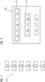
- Fig. 2 schematically illustrates an architecture of a computing device for path planning for a mobile non-circular robot in an environment comprising obstacles.
- the computing device is generally referred to by the reference sign 200.
- the computing device 200 comprises a 3D costmap receiving interface 204 configured for receiving a 3D costmap.
- the 3D costmap comprises a 2D map of a plane, in which a mobile non-circular robot is movable.
- the 3D costmap further comprises a cost value, for each position on the 2D map, indicative of a cost of a positioning, and/or a movement, of the mobile non-circular robot in the presence of one or more obstacles in a predetermined environment of the position.
- the positioning and/or movement comprises an orientation of the mobile non-circular robot.
- the computing device 200 further comprises a start and end positions receiving interface 206 configured for receiving a start position and an end position of the mobile non-circular robot on the 3D costmap.
- the start position comprises a start orientation of the mobile non-circular robot
- the end position comprises an end orientation of the mobile non-circular robot.
- the computing device 200 further comprises a consecutive positions selecting module 208 configured for iteratively selecting consecutive positions for a path to be planned, starting at the received start position and terminating at the received end position.
- the iteratively selecting comprises minimizing a cumulative cost value of the consecutive positions.
- the cumulative cost value comprises a sum of the cost values of the consecutive positions (e.g., according to the received 3D costmap).
- the cumulative cost value further comprises a stress value.
- the stress value may be indicative of a change in a movement direction along the planned path.
- the computing device 200 still further comprises a planned path outputting interface 210 configured for outputting the planned path based on the iteratively selected consecutive positions.
- the computing device 200 comprises a 3D costmap generating module 202 configured for generating the 3D costmap.
- the computing device 200 may comprise a 3D costmap updating module (not shown in Fig. 2 ) configured for updating the 3D costmap responsive to a change in positions of one or more obstacles.
- the computing device 200 comprises a planned path executing module 212 configured for executing, by the mobile non-circular robot, the output planned path.
- the computing device 200 may further comprise a memory 214.
- Any one of the 3D costmap receiving interface 204, the start and end positions receiving interface 206, and the planned path outputting interface 210 may be comprised in a (e.g., common) input-output interface 216.
- the consecutive positions selecting module 208, and optionally the 3D costmap generating module 202 may be comprised in, and/or implemented by, a processor 218 (e.g., a central processing unit, CPU, and/or a graphics processing unit, GPU).
- a processor 218 e.g., a central processing unit, CPU, and/or a graphics processing unit, GPU.
- the computing device 200 may be configured for performing the method 100.
- a system may comprise the computing device 200 and the mobile non-circular robot.
- the computing device 200 may be comprised in the mobile non-circular robot.
- the ROS Navigation stack [1] is a commonly used software package that tackles navigation problems for mobile robots.
- its underlying environmental representation in the form of a two-dimensional (2D) costmap (and/or a 2D grid) is only well suited for circular robots (also denoted as round robots), where the minimum distance between the robot's center of rotation (and/or base link) and obstacles is constant.
- the constant minimum distance relaxes the problem of collision checks for a pose (e.g., comprising x-y position and orientation), as the orientation does not affect whether the round robot's base link can be on a specific x-y position.
- computing resources may be saved, and/or the iterative selection S108 of consecutive positions for the path planning (also denoted as graph search) and the cumulative cost value (also denoted as cost calculation) can be optimized, in particular to allow for online (and/or real-time) performance (e.g., calculation) on the robot.
- the inventive technique provides a solution, which can reduce the computational effort for any one of the cases, while also proposing to integrate "comfort" factors to the path planning (also denoted as path generation, and/or graph search), such as a reduction of directional changes, and/or the preferred orientation (also denoted as heading) of the robot during the path.
- the inventive technique may also be denoted as technique for free path planning for (in particular omnidirectional) non-round (and/or non-circular) robots in a previously mapped environment.
- the inventive technique may further be denoted as technique for collision-free and orientation-optimized path planning for anyshape (e.g., holonomic) robots.
- the inventive technique may, e.g., comprise an algorithm for performing the method 100.
- the algorithm may briefly be denoted as "HunGreedy".
- the inventive technique for path planning for non-circular (in particular holonomic) robots may utilize the commonly used grid-map representation of the environment to create a 3D costmap that encodes the (e.g., true) cost of a node (and/or cell) for an oriented anyshape robot regarding collisions and proximity to Obstacles.
- the 3D costmap may then be traversed using a customized implementation of known graph-search algorithms like A* or D*-Lite.
- the inventive technique uses a novel approach (e.g., in terms of the cumulative cost value) to reward the progress towards the goal (and/or end position), as well as using a preferred orientation along the path and change of directions (e.g., corresponding to stress), therefore producing paths that are collision-free, orientation-optimized and stress reduced.
- HunGreedy of the inventive algorithm may resemble the characteristics of the implementation, which may be resource hungry when generating the 3D costmap (also denoted as pre-calculations, and/or used data structures), but may lead to short planning times due to a greedy search approach.
- the environment representation in the form of the 2D grid can be further used as a basis because it is independent from the robot model.
- the data basis needs to be extended.
- the goal is to create a 3D grid map whose third dimension describes the robot orientation from 0 degrees to 359 degrees (and/or in the interval of [0,2 ⁇ )).
- N 360 degrees/angle resolution, and/or 2 ⁇ /angle resolution
- x-y grid maps are generated.
- the rotated (e.g., about an axis passing through the center of mass of the robot) footprints of the (in particular non-circular) robot are first determined by projecting the non-circular robot footprint (also denoted as robot floor plan) into the grid area and multiplied (and/or rotated) N times by the parameterizable angular resolution (e.g., 1 degrees).
- the parameterizable angular resolution e.g. 1 degrees
- the cost values of the individual nodes (and/or individual cells) are summed up (and, e.g., normalized), so that also each 3D node (and/or 3D cell) is assigned a cost value, which indicates the proximity to obstacles.
- the 3D node (and/or 3D cell) is also marked as lethal.
- path planning also denoted as graph search
- path planning also denoted as graph search
- different parameters may be taken into account individually, or (at least partially) jointly.
- a kinematic model (also denoted as motion model) may be taken into account.
- a movement can occupy 1-3 dimensions.
- the value M may be reduced (e.g., for Differential and/or Ackermann steering geometries), making the approach optionally adaptable to non-holonomic robots.
- a stress value may be taken into account. Movements that allow paths (also denoted as trajectories) with few changes of direction may be rated well.
- the stress value (also denoted as stress rating) favors smooth and natural movements, although more "jerky” paths may be possible. This may be particularly relevant in case the robot moves at a high speed, and/or whenever the effect of inertia becomes relevant.
- safety areas also denoted as protective fields
- Autonomous robots are usually equipped with safety areas (and/or protective fields), which are not directly part of the robot footprint (and/or robot floor plan) but can restrict the robot's freedom of movement.
- (E.g., Virtual) collisions with the safety areas (and/or protective fields) may be planned in advance and avoided.
- Including safety areas (and/or protective fields) in the path planning has an effect on the stress value of the path. E.g.,
- safety areas may be required to compensate for effects of inertia of a robot moving at high momentum.
- the basic data structure is extended compared to the conventional navigation approach as, e.g., in ROS [1].
- the inventive technique extends the kinematic model to holonomic robots compared to the previous approach of [4].
- the stress value (and/or stress determination) of the planned path (and/or the trajectory) at path planning time, and/or the safety area (and/or protective field) integration in the stress value (and/or determination) is unique to the inventive technique.
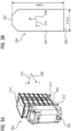
- Figs. 3A and 3B schematically illustrate an example of a mobile non-circular robot 300.
- the robot 300 of the illustrative example is equipped with an omnidirectional (and/or holonomic) mecanum drive with wheels 312. Due to its sensor setup for obstacle avoidance, the exemplary robot 300 of Figs. 3A and 3B has a preferred movement direction of facing forwards 302 while driving.
- the purpose of the robot 300 is to transport rectangular goods, e.g., transport boxes 314 on a carriage.
- Fig. 3A the robot 300 is illustrated in a perspective view with a stack of transport boxes 314.
- Fig. 3B schematically illustrates the footprint (and/or projection onto the 2D floor plan, and/or 2D map of the plane) of the robot 300.
- the robot 300 comprises a front 302, back 306 and sides 304.
- a reference frame e.g., of, and/or aligned with the footprint
- the lateral (and/or transversal extension of the robot 300 is 0.37m
- the longitudinal extension of the robot 300 is 0.89m.
- Fig. 4 exemplarily illustrates a 2D map of a plane of an environment 400 with obstacles 402 in the form of walls. Empty spaces, corridors, and/or hallways 404 are provided between the obstacles 402.
- the environment 400 may, e.g., correspond to (and/or may comprise) a lab space, and/or a factory floor.
- the exemplary environment 400 of Fig. 4 that the robot 300 may be placed in, comprises several critical sections.
- the width of hallways is set to a value only marginally bigger than the width of the exemplary robot 300 itself, creating areas where changes in the orientation (also denoted as in-place rotations) of the robot 300 are not possible without causing a collision.
- Fig. 4 shows the exemplary 2D map created using a simulated 2D-lidar and a SLAM algorithm ([5], [6]).
- the exemplary 2D map has a resolution of 2.5cm and counts 549 ⁇ 412(x-y) nodes (and/or cells), resulting in a map size of 13.7125m ⁇ 10.2875m, and requiring 266.188KB of memory.
- the underlying grid has a node distance (and/or cell size) of 1m per grid direction (and/or per cell side) and may be used for size and distance comparison.
- navigation requests e.g., each comprising a start point 502 and end point 506 with predetermined orientations of the robot
- navigation requests e.g., each comprising a start point 502 and end point 506 with predetermined orientations of the robot
- the start point 502 is connected by the planned path 504 to the end point 506.
- Sections of collisions with obstacles, in particular walls 402 are shown at reference sign 508 in each figure. The collisions take place when the robot follows the conventionally planned 2D paths.
- the start orientation which faces forward in each of the exemplary illustrations of Figs. 5 , 6 , 7A and 7B , and the end orientation (also denoted as target orientation) are displayed by the arrow directions at reference sign 502 and 506, respectively.
- the orientation along the path is generically facing forwards (towards the next pose, and/or the consecutive position and orientation), except when close to the start pose and/or end pose (also denoted as goal pose), where the robot is allowed to move more freely to reach the next desired orientation (and/or rotation) more quickly.
- Fig. 5 shows a long-distance example that causes a collision at reference sign 508 right before delivering the goods into the exemplary loading bay at the end position 506.
- reference signs 510-1 and 510-2 exemplarily, footprints of the robot (e.g., as shown in Fig. 3B ) are shown with different orientations leading to the collision 508 when transitioning from the first orientation 510-1 to the second orientation 510-2.
- Fig. 5 surrounding the obstacles (e.g., walls) 402, differently shaded areas 512-1 and 512-2 denote nodes (and/or cells) with decreasing cost values, with the unshaded area at reference sign 514 denoting nodes (and/or cells) with vanishing cost value.
- Fig. 6 illustrates a (e.g., more difficult) example, in which the robot should reach the center of a tight spiral, which is difficult but possible. Solving the problem of determining a collision-free path conventionally requires the robot to move closer to the obstacles (in particular walls) 402, which an inflation layer prevents.
- the inflation layer may comprise a tool that artificially extends obstacles in a 2D map by the circumscribing radius of a robot instead of actually projecting the robot's footprint into the map.
- the inflation layer reduces the computational effort for path planning significantly, as now only nodes (and/or cells) that are further away than the radius R from an obstacle are valid.
- the 2D map of Fig. 4 may be denoted as original map, and the schematic presentation in Fig. 5 may be denoted as inflated map and/or 2D costmap.
- the darker shaded areas at reference sign 512-1 may mark "inflated lethal" nodes (and/or "inflated lethal” cells), e.g., meaning the distance to obstacles (e.g., walls 402) is less than a round robot's radius R, and therefore it is sure that there would be a collision.
- the lighter shaded areas at reference sign 512-2 may mark decreasing cost values (and/or cell costs), e.g., that indicate that obstacles (e.g., walls 402) are close.
- the decreased cost values close to obstacles may help to, e.g., keep more distance (e.g., according to a safety area, and/or protective field) to walls around corners.
- the darker shaded area at reference sign 512-1 in Fig. 5 may indicate a node (and/or cell), for which a collision with a nearby obstacle (e.g., wall 402) occurs for any orientation of the robot.
- the lighter shaded area at reference sign 512-2 in Fig. 5 may indicate a node (and/or cell), for which a collision with the nearby obstacle (e.g., wall 402) only occurs for some orientations of the mobile non-circular robot (e.g., the longitudinal direction of the robot pointing towards the obstacle).
- Figs. 7A and 7B provide examples of an initially facing forward mobile non-circular robot, as indicated by the arrow of the start position 502, with two different orientations of the end position, as indicated by the direction of the arrow at reference sign 506. If the robot enters the corridor (also denoted as hallway) facing forward and only attempts to change the orientation at the end position 506, several collisions with obstacles (in particular walls) as indicated at reference signs 508 occur.
- corridor also denoted as hallway
- a collision-free path along the same corridor (and/or hallway) exists and is found by the inventive technique, in which the robot first rotates, as indicated at reference sign 1202 in Fig. 12A , and then moves through the corridor (and/or hallway) facing backwards.
- conventional path planning algorithms are not capable of detecting the collision-free path.
- the information that there is no connection between the end (and/or goal) orientation and the positions just before is missing in the conventional 2D costmap.
- the inflation layer (IL) of the conventional 2D costmap is (e.g., conventionally) determined (and/or calculated) using the short side of a non-circular robot, the IL only covers a circular robot with the radius of the short side for collision checks.
- Such a circular robot can traverse the corridor (and/or hallway), as it can rotate there, but a non-circular (and/or long) robot cannot traverse the corridor (and/or hallway), as the positions of the non-circular (and/or long) robot between the two orientations (e.g., 0 degrees and 90 degrees) would cause collisions with the walls.
- the information on the longitudinal direction of the mobile non-circular robot is missing in the conventional inflated map (and/or 2D costmap), as it does not account for the robot's orientation, and therefore does not indicate (and/or parameterize, and/or know) that there would be collisions.
- the conventional search algorithms therefore consider moving through the nodes (and/or cells) of the IL as valid and plan a path that cannot be executed without collisions.
- the inventive technique produces no (e.g., direct) connection between the two orientations, as they would cause collisions.
- path planning and/or graph-searching
- the 3D costmap there is no direct connection, and therefore no path is planned through that passage.
- Fig. 7B the exists no collision-free path using the displayed straight corridor (and/or hallway, and/or passage), even when rotating before entering the corridor (and/or hallway, and/or passage), due to the tightness (and/or narrowness) of the straight corridor (and/or hallway, and/or passage) and the T-shaped junction with a second corridor (and/or hallway, and/or passage).
- start pose 502 and end pose 506 of Fig. 7B the robot has to take a completely different route, entering the second corridor (and/or hallway, and/or passage) from the left rather than from above, as shown in Fig. 12B , where the collision-free path has been found by the inventive technique.
- the programs implementing the method 100 have been successfully tested on a system with an AMD Ryzen 5 3600 processor and 16GB RAM that runs Linux Ubuntu 20.04 and ROS Noetic.
- the developed planner e.g., comprising the consecutive positions selecting module 208, the processor 218, and/or embodied by the computing device 200
- Using multiple threads can reduce the calculation time by a factor N, where N is the number of threads created.
- N is the number of threads created.
- using four threads can reduce the times provided in Table I by a factor of four, making it much more suitable (and/or viable) for real-time applications.
- Using multiple threads can potentially even eliminate the need to generate in advance (and/or preprocess) the 3D costmap.
- Pointers may be smart pointers (e.g., std::shared ptr) to eliminate the workload of manual memory management.
- the 2D map of the plane (also denoted as 2D costmap) composed of nodes (also denoted as x-y cells) must be extended, according to the inventive technique, to include information about the robot's orientation and the resulting cost values (also denoted as cell costs).
- a data structure "ExtendedCostmap” was created and filled with information of the inventive technique.
- the data structure "ExtendedCostmap” comprises the following main elements:
- An inlier point may comprise a node lying within the oriented footprint (and/or within the oriented convex hull) of the robot.
- Determining inlier points of an oriented footprint is generally a time-consuming process that scales with map precision and footprint size and complexity.
- the inlier points for a specific orientation match for all (e.g., x-y) positions and can therefore be determined offline in advance (also denoted as pre-computed), e.g., instead of recalculating them for each node (and/or cell).
- Algorithm 1 describes the process of determining the inlier points in pseudocode.
- Algorithm 1 first the size of the array storing the footprints is set using the desired angular resolution. Then a pose is created for each resulting angle, and the convex (e.g., hull) filling nodes (and/or cells) as well as the nodes, (and/or cells) that the outline of the footprint of the robot occupies, are collected and stored in the array. If this gathering fails due to some points being outside of the (e.g., 2D) map, the process has to be aborted, as in this case only incomplete collision checks can be performed during the creation of the 3D costmap.
- the convex e.g., hull
- Figs. 8A, 8B and 8C shows examples of oriented footprints, with front 302 and rear (also denoted as back) 306 of the robot 300 and the matching inlier points.
- the used footprint corresponds to the footprint of the robot 300 with freight as shown in Fig. 3A and 3B with a footprint padding of 3.5cm that enforces spacing (e.g., corresponding to the safety areas, and/or protective fields) between obstacles (e.g., walls 402) and the robot. Without padding, the collision checks later would allow zero distance between walls 402 and the robot chassis, which could potentially result in collisions (e.g., due to the, in particular loaded, robot's inertia).
- a first and second (e.g., mutually orthogonal) direction of the grid is shown.
- the rotation axis (e.g., located at the center of mass) of the robot 300 is indicated.
- a node 806 e.g., representing a cell of the 2D map (and/or grid) is schematically depicted.
- the orientation of the robot 300 is rotated by 45 degrees (and/or by ⁇ /4) and by 90 degrees and/or by ⁇ /2), respectively, relative to the orientation of the robot 300 in Fig. 8A .
- the cost value (and/or cell cost) of each node (and/or x-y yaw-cell), in an exemplary embodiment, is calculated by adding the 2D cost values (and/or cell costs) of the inlier points of the footprint on the matching pose.
- the (e.g., x-y) positions of each inlier point only have to be shifted according to the relative shift from the previously determined position (also denoted as precomputation-position).
- the 3D node (and/or cell) may also be marked as blocked, and/or lethal.
- a generation function is performed that iterates through all (e.g., three) dimensions (in particular comprising yaw, x and y) and tries to determine (e.g., compute) the cost value, if possible (e.g., only for positions lying sufficiently away from an outer boundary of the environment, outside of which the 2D map of the plane is unknown).
- the costmap is initialized with the expected size and a cost value that resembles an UNKNOWN (e.g., node, and/or cell) cost value, which is treated as non-traversable during path planning.
- UNKNOWN e.g., node, and/or cell
- the outermost dimension being the angular dimension, it is also possible to relax the determination (e.g., calculation) problem for unavailable footprints by skipping the angle and therefore leaving all nodes (and/or) cells (e.g., and therefore all poses with that orientation) UNKNOWN and therefore non-traversable.
- the algorithm effectively skips Size X ⁇ Size Y nodes (and/or cells), e.g., corresponding to the size of the 2D map (and/or the whole 2D costmap), and therefore reduces calculation time.
- Algorithm 2 describes the process of determining the (e.g., complete) 3D costmap in pseudocode.
- the algorithm can proceed with shifting the footprint so that its center (e.g., of mass) matches the coordinates of each (e.g., x-y) position requested. If the shift encounters at least one inlier point being moved outside of the map boundaries of the 2D map, the position is considered as invalid, and therefore all calculations may be skipped (e.g., nodes, and/or cells, remain UNKNOWN), which saves Size Y computations for (e.g., x) positions along a first grid direction (e.g., at reference sign 802 in Figs. 8A, 8B and 8C ) close to the map boundaries. For (e.g., y) positions along a second grid direction (e.g., at reference sign 804 in Figs. 8A, 8B and 8C ), only a single calculation may be skipped due to the implementation.
- a first grid direction e.g., at reference sign 802 in Figs. 8A, 8B and 8C
- Figs. 9A and 9B exemplarily illustrate oriented 3D costmaps (e.g., that result from the determinations, and/or calculations, as described herein).
- White areas mark nodes (and/or cells) that are traversable (e.g., corresponding to a vanishing cost value) with the given orientation of the robot 300.
- Dark nodes (and/or cells) indicate (e.g., potential) collisions, and/or non-traversable nodes (and/or cells).
- the footprint at reference sign 300 in each of the Figs. 9A and 9B displays the orientation of the robot 300 for the displayed (e.g., 3D) costmap.
- Areas close to (and/or around) the outer boundaries of the (e.g., 2D) map are non-traversable as the footprint may not be shifted completely, which makes the nodes (and/or cells) close to the boundary uncertain (and/or unknown).
- the width of the white areas (and/or corridors), corresponding to the cost values of the positions (and/or nodes) depends on the orientation of the non-circular robot 300.
- Table I shows some examples for the resulting number of nodes (and/or cells), the calculation time and the memory requirements in relation to the desired angular precision (which may also be denoted as angular resolution).
- the parameters of the underlying map correspond to those described in connection with the embodiment of Figs. 3A, 3B and 4 .
- As a large part of the map usually does not change too much between power cycles of a robot, it makes sense to save the computed map (e.g., to a hard disk, for example of the computing device 200) and load it at startup (e.g., of the computing device 200, and/or of the method 200) to avoid repeating the computational effort (e.g., of generating the 3D costmap according to the step S102).
- the path planning is limited to a static environment without accounting for dynamic obstacles.
- a section-wise updating algorithm may be integrated that searches for changes in the 2D grid and then updates all surrounding 3D nodes (and/or cells) within a predetermined radius, which may correspond to the circumscribing distance of the footprint.
- the furthest inlier point from the rotational center As the furthest inlier point from the rotational center will travel the furthest during rotations, it sets the minimum precision for no inlier point to travel more than one node (and/or cell) for each rotation step.
- the distance to the furthest inlier point from the rotational center may also be known as the circumscribing radius of the robot's footprint, and/or may be obtained using the planar (e.g., x and y) values of the furthest footprint point.
- n steps can be used to obtain an approximation of the required precision per step that ensures that no part of the robot travels further than one node (and/or cell) per step.
- Skipping a node (and/or cell) may potentially produce paths (and/or connections) between nodes (and/or cells) that are not collision-free.
- the basic (and/or baseline) algorithm structure in the exemplary embodiments is similar to conventional graph search algorithms, e.g., A* or D*-Lite, also utilizing the concepts of a priority queue, a closed list, and a cost function to calculate the cost value to reach a node (and/or cell), including some form of heuristics to speed up the search process.
- inventive technique e.g., comprising the algorithm, however, differs in important implementation details.
- each node also denoted as x-y-yaw-cell
- x-y-yaw-cell e.g., in a graph
- the cost in the above list may correspond to the cumulative cost value in the step S108 of iteratively selecting consecutive positions.
- Algorithm 3 describes the path planning, in particular the step S108 of iteratively selecting consecutive positions, (also denoted as graph search algorithm) of an embodiment in pseudocode.
- An aspect, that may affect the behavior of the algorithm the most, is the calculation and composition of the cost value per node (and/or node cost).
- the corresponding weights for the cost type may be set to zero (e.g., to disable the cost type).
- the conventional A* implementation uses two types of cost: The cost for traversing from one node (and/or cell) to another (including the cost value of the node, and/or cell cost), and a heuristic function towards the end position (and/or goal).
- the conventional A* algorithm does not account for other factors measuring the quality of a path, which are therefore not considered (e.g., not at all) during path planning.
- the equations for the corresponding factors must be formulated.
- the cost value of a parent node usually being included in the cost of its child node, the values of the nodes (and/or cells) rapidly increase with the number of nodes (and/or cells) traversed. Therefore, the cost equations preferably aim to reduce the effect of previous nodes, if possible, in order to represent their true potential more accurately.
- the inventive technique merges both factors, which results in "free" movements towards the end position (and/or goal).
- the inventive technique develops the cost value per node (and/or node cost), and/or focuses on very greedy searches for path planning towards the end position (and/or goal).
- Most robots including the exemplary robot 300 of Figs. 3A and 3B , have a preferred direction of movement.
- the heading while moving may be rated by converting the movement shift from an index unit to a movement vector.
- the (e.g., x and y) values e.g., along a first and second direction on the plane, and/or on the 2D grid) of the shift may be multiplied by sine factors, and/or cosine factors of the orientation of the parent node (and/or cell).
- yaw Coords Parent ,yaw ⁇ angular _ precision ;
- v x cos yaw ⁇ ms .x + sin yaw ⁇ ms .y ;
- v y sin yaw ⁇ ms .x + cos yaw ⁇ ms .y .
- Eqs. (9) and (10) do not differentiate between positive and negative values, situational factors may be applied depending on the actual direction (e.g., w x,pos ).
- a crucial aspect for path planning (and/or trajectory calculations), including the speed (also denoted as execution speed) for the robot executing the planned path, is to minimize the change of movement directions, as the changes of movement directions often require the speed (also denoted as velocity) to come down (e.g., close) to zero for that dimension (and/or change in direction).
- the maximum speed (and/or velocity) on the section (e.g., of the planned path) is limited, in particular beforehand, e.g., due to the robot's (negative, and/or positive) acceleration limits.
- the parameter values were empirically determined by manually evaluating the planned paths (and/or produced paths).
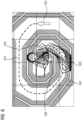
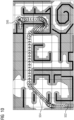
- Figs. 10 , 11 , 12A and 12B each show the planned path (and/or produced path) according to the inventive technique at reference sign 504, as well as the projected footprints for each pose on the path (e.g., around the path 504), and the exploration state of the 3D costmap.
- the exploration state of the 3D costmap is displayed by counting the visited angles per node (e.g., x-y-cell), where fully explored (in particular traversable) nodes (and/or cells) (e.g., 360 degrees, and/or 2 ⁇ ) appear as white, and non-explored (and/or explored as non-traversable) nodes (and/or cells) are dark.
- node e.g., x-y-cell
- fully explored (in particular traversable) nodes (and/or cells) e.g., 360 degrees, and/or 2 ⁇
- non-explored (and/or explored as non-traversable) nodes (and/or cells) are dark.
- nodes (and/or cells) there are a lot of nodes (and/or cells) that may be traversable in Figs. 10 , 11 , 12A and 12B , which are still marked in dark because they have not been explored in the step S108 of iteratively selecting consecutive positions (and/or by the inventive path planning, and/or path search, algorithm).
- the existence of unexplored nodes (and/or cells) is favorable (and/or good), as it shows the direction and/or the focus of search (e.g., avoiding veering away from the end position 506), which reduces computational effort if not all nodes (and/or cells) are explored and a (in particular collision-free) path is still found.
- Table II shows exemplary details about the planned (and/or produced) paths, runtime requirements and the number of explored nodes according to the inventive technique.
- Table II shows exemplary details about the planned (and/or produced) paths, runtime requirements and the number of explored nodes according to the inventive technique.
- Fig. 10 schematically illustrates case 1 from Table II of long distance (e.g., path) planning including an exploration state for the 2D map of Fig. 4 .
- test case 1 only having had a problematic section at the delivery point, the results shown in Fig. 10 show that, using the inventive technique, there was room for more optimization regarding movements.
- the exploration state of the map for the example of Fig. 10 also shows how difficult finding the path actually was, considering how many areas of the map are fully explored (e.g., white). However, it is hard to improve the situation of the exploration state as the algorithm may get stuck in local minima, e.g., for even more maze-like maps.
- Fig. 10 the algorithm proved to produce orientation-optimized paths.
- the only exception in Fig. 10 is the first (on the left-hand side of Fig. 10 ) vertical hallway section, where the effort to perform, e.g., multiple (e.g., two or three) successive, 90 degrees (and/or by ⁇ /2) rotations is valued higher (and/or more expensive) than traversing more sideways and therefore closer to walls.
- the effort to perform e.g., multiple (e.g., two or three) successive, 90 degrees (and/or by ⁇ /2) rotations is valued higher (and/or more expensive) than traversing more sideways and therefore closer to walls.
- one or two successive 90 degrees (and/or by ⁇ /2) rotations may be more expensive (and/or may lead to a higher cumulative cost value) than (in particular two) rotations by 45 degrees (and/or ⁇ /4), and/or driving sideways.
- the exploration state and the low calculation time of test case 2 of Table II, schematically illustrated in Fig. 11 shows how good the algorithm works for more enclosed spaces, such as a spiral.
- the planned path (and/or produced path) is also collision-free, proving the inventive technique's (and/or algorithm's) ability to plan (and/or produce) collision-free maneuvers in enclosed spaces.
- Fig. 12A case 3 of Table II is shown.
- the robot rotates, as indicated at reference sign 1202, before entering the corridor (and/or hallway) backwards.
- the solution of the inventive technique for case 3 looks as expected with the robot turning before entering the narrow corridor (and/or hallway). It is notable that, according to the inventive technique, the non-preferred but necessary backwards movements are among the path solutions.
- Fig. 12B case 4 of Table II is shown.
- an alternative collision-free path 504 (also denoted as route) is found instead of the non-traversable corridor (and/ hallway).
- Case 4 also shows the expected outcome. With the search starting from the end position (and/or goal) 506, the exploration state of case 4 shows no direct connection through the corridor (and/or hallway), as there is no collision-free node connection for the tight corner, which leads to the alternative path (and/or route) around the corridor (and/or hallway) .
- a 3D costmap is received.
- the 3D costmap comprises a 2D map of a plane and a cost value per position on the 2D map, indicative of a cost of positioning the robot with a predetermined orientation in the presence of obstacles in a vicinity of the position.
- a start position and an end position of the robot are received comprising a start and an end orientation of the robot, respectively.
- Consecutive positions for a path in planning are iteratively selected from the start position to the end position.
- a cumulative cost value of the consecutive positions, which comprises a sum of the cost values, is minimized.
- the cumulative cost value further comprises a stress value, e.g., indicative of a change in a movement direction along the planned path.
- the benchmarking results of Table II prove the inventive technique's (e.g., comprising the algorithm, the method 100, the computing device 200, and/or the system comprising the computing device 200 and the mobile non-circular robot) ability to solve advanced navigation problems for the example anyshape (and/or non-circular) footprint and a holonomic drive of the robot 300 of Figs. 3A and 3B .
- the approach is also applicable for any other shape.
- the inventive technique proves to be able to produce longer paths through more open spaces, while outperforming the conventional approaches both in map resolution and calculation time.
- the definition of a path quality is shifted towards real applications.
- difficult paths may be pre-processed (e.g., the 3D costmap generated in advance) and loaded from a memory (e.g., disk), e.g., of the computing device 200.
Landscapes
- Engineering & Computer Science (AREA)
- Radar, Positioning & Navigation (AREA)
- Remote Sensing (AREA)
- Automation & Control Theory (AREA)
- Physics & Mathematics (AREA)
- General Physics & Mathematics (AREA)
- Robotics (AREA)
- Mechanical Engineering (AREA)
- Aviation & Aerospace Engineering (AREA)
- Control Of Position, Course, Altitude, Or Attitude Of Moving Bodies (AREA)
Priority Applications (2)
| Application Number | Priority Date | Filing Date | Title |
|---|---|---|---|
| US18/585,741 US20240286286A1 (en) | 2023-02-28 | 2024-02-23 | Technique of path planning for a mobile non-circular robot |
| CN202410215833.3A CN118565473A (zh) | 2023-02-28 | 2024-02-27 | 用于非圆形移动机器人的路径规划的技术 |
Applications Claiming Priority (1)
| Application Number | Priority Date | Filing Date | Title |
|---|---|---|---|
| EP23159114 | 2023-02-28 |
Publications (1)
| Publication Number | Publication Date |
|---|---|
| EP4425293A1 true EP4425293A1 (de) | 2024-09-04 |
Family
ID=85792244
Family Applications (1)
| Application Number | Title | Priority Date | Filing Date |
|---|---|---|---|
| EP23165592.9A Pending EP4425293A1 (de) | 2023-02-28 | 2023-03-30 | Verfahren zur wegplanung für einen mobilen nichtkreisförmigen roboter |
Country Status (3)
| Country | Link |
|---|---|
| US (1) | US20240286286A1 (de) |
| EP (1) | EP4425293A1 (de) |
| CN (1) | CN118565473A (de) |
Families Citing this family (2)
| Publication number | Priority date | Publication date | Assignee | Title |
|---|---|---|---|---|
| WO2025102156A1 (en) * | 2023-11-14 | 2025-05-22 | Avidbots Corp | Software systems and method for a semi-autonomous floor cleaning apparatus for navigation of tight spaces |
| CN120008614B (zh) * | 2025-04-16 | 2025-07-08 | 盛视科技股份有限公司 | 一种窄道脱困路径规划方法及智能机器人 |
Family Cites Families (6)
| Publication number | Priority date | Publication date | Assignee | Title |
|---|---|---|---|---|
| US6259988B1 (en) * | 1998-07-20 | 2001-07-10 | Lockheed Martin Corporation | Real-time mission adaptable route planner |
| EP2821875A3 (de) * | 2008-09-03 | 2015-05-20 | Murata Machinery, Ltd. | Routenplanungsverfahren, Routenplanungseinheit und autonomes Mobilgerät |
| US10293485B2 (en) * | 2017-03-30 | 2019-05-21 | Brain Corporation | Systems and methods for robotic path planning |
| JP6897376B2 (ja) * | 2017-07-11 | 2021-06-30 | トヨタ自動車株式会社 | 移動計画装置、移動ロボット、および移動計画プログラム |
| US10899006B2 (en) * | 2018-05-01 | 2021-01-26 | X Development Llc | Robot navigation using 2D and 3D path planning |
| US11199853B1 (en) * | 2018-07-11 | 2021-12-14 | AI Incorporated | Versatile mobile platform |
-
2023
- 2023-03-30 EP EP23165592.9A patent/EP4425293A1/de active Pending
-
2024
- 2024-02-23 US US18/585,741 patent/US20240286286A1/en active Pending
- 2024-02-27 CN CN202410215833.3A patent/CN118565473A/zh active Pending
Non-Patent Citations (9)
| Title |
|---|
| B. LAUC. SPRUNKW. BURGARD: "Efficient grid-based spatial representationsfor robot navigation in dynamic environments", ROBOTICS AND AUTONOMOUS SYSTEMS, October 2013 (2013-10-01), pages 1116 - 1130 |
| DAKULOVIC MARIJA ET AL: "Efficient navigation for anyshape holonomic mobile robots in dynamic environments", 2013 IEEE/RSJ INTERNATIONAL CONFERENCE ON INTELLIGENT ROBOTS AND SYSTEMS(ROS), IEEE, 3 November 2013 (2013-11-03), pages 2644 - 2649, XP032537303, ISSN: 2153-0858, [retrieved on 20131226], DOI: 10.1109/IROS.2013.6696729 * |
| E. MARDER-EPPSTEINE. BERGERT. FOOTE: "The Office Marathon: Robust Navigation in an Indoor Office Environment", IEEE INTERNATIONAL; CONFERENCE ON ROBOTICS AND AUTOMATION, 2010 |
| G. GRISETTIC. STACHNISSW. BURGARD: "Improved Techniques for Grid Mapping with Rao-Blackwellized Particle Filters", IEEE TRANSACTIONS ON ROBOTICS, vol. 23, 2007, pages 34 - 46 |
| G. GRISETTIC. STACHNISSW. BURGARD: "Improving Grid-based SLAM with Rao-Blackwellized Particle Filters by Adaptive Proposals and Selective Resampling", PROC. OF THE IEEE INTERNATIONAL CONFERENCE ON ROBOTICS AND AUTOMATION (ICRA, 2005 |
| M. DAKULOVICC. SPRUNKL. SPINELLOIVAN PETROVICW. BURGARD: "Efficient Navigation for Anyshape Holonomic Mobile Robotsin Dynamic Environments", IEEE/RSJ INTERNATIONAL CONFERENCE ON INTELLIGENT ROBOTS AND SYSTEMS, 2013 |
| R. SAMANIEGOJ. LOPEZF. VAZQUEZ: "Path Planning for Non-Circular, Non-Holonomic Robots in Highly Cluttered Environments", SENSORS, August 2017 (2017-08-01) |
| S. KOENIGM. LIKHACHEV, PROCEEDINGS OF THE EIGHTEENTH NATIONAL CONFERENCE ON ARTIFICIAL INTELLIGENCE AND FOURTEENTH CONFERENCE ON INNOVATIVE APPLICATIONS OF ARTIFICIAL INTELLIGENCE, 2002 |
| SAMANIEGO RICARDO ET AL: "Path Planning for Non-Circular, Non-Holonomic Robots in Highly Cluttered Environments", vol. 17, no. 8, 15 August 2017 (2017-08-15), CH, pages 1876, XP093076461, ISSN: 1424-8220, Retrieved from the Internet <URL:https://doi.org/10.3390/s17081876> DOI: 10.3390/s17081876 * |
Also Published As
| Publication number | Publication date |
|---|---|
| CN118565473A (zh) | 2024-08-30 |
| US20240286286A1 (en) | 2024-08-29 |
Similar Documents
| Publication | Publication Date | Title |
|---|---|---|
| Mahulea et al. | Path planning of cooperative mobile robots using discrete event models | |
| US12242272B2 (en) | Path planning in mobile robots | |
| Kelly | Mobile robotics: mathematics, models, and methods | |
| Elbanhawi et al. | Sampling-based robot motion planning: A review | |
| Claes et al. | Multi robot collision avoidance in a shared workspace | |
| EP4425293A1 (de) | Verfahren zur wegplanung für einen mobilen nichtkreisförmigen roboter | |
| Ghita et al. | Trajectory planning for a car-like robot by environment abstraction | |
| Ali et al. | An algorithm for multi-robot collision-free navigation based on shortest distance | |
| Đakulovic et al. | Complete coverage path planning of mobile robots for humanitarian demining | |
| Sainte Catherine et al. | A modified hybrid reciprocal velocity obstacles approach for multi-robot motion planning without communication | |
| Bhargava et al. | An omnidirectional mecanum wheel automated guided vehicle control using hybrid modified A* algorithm | |
| Stentz | The NAVLAB system for mobile robot navigation | |
| Vasseur et al. | Navigation of car-like mobile robots in obstructed environments using convex polygonal cells | |
| Ben-Shahar et al. | To push or not to push: on the rearrangement of movable objects by a mobile robot | |
| Ng | An analysis of mobile robot navigation algorithms in unknown environments | |
| Adriansyah et al. | Optimization of circular robot size using behavior based architecture | |
| Song et al. | Collision and rollover-free g 2 path planning for mobile manipulation | |
| CN115237125A (zh) | 一种无人配送消毒小车的智能线路规划方法 | |
| Stentz | Multi-resolution constraint modeling for mobile robot planning | |
| US20260048507A1 (en) | Motion planning and/or collision determination using continuous environment model | |
| Patel et al. | Exploration with ARWS | |
| Hacohen et al. | A navigation function for uncertain environment | |
| Xidias et al. | Path planning of holonomic and non-holonomic robots using bump-surfaces | |
| Charabaruk et al. | Design and development of an autonomous omnidirectional hazardous materials handling robot | |
| Zhao | Theoretical and experimental studies of mobile robot navigation |
Legal Events
| Date | Code | Title | Description |
|---|---|---|---|
| PUAI | Public reference made under article 153(3) epc to a published international application that has entered the european phase |
Free format text: ORIGINAL CODE: 0009012 |
|
| STAA | Information on the status of an ep patent application or granted ep patent |
Free format text: STATUS: THE APPLICATION HAS BEEN PUBLISHED |
|
| AK | Designated contracting states |
Kind code of ref document: A1 Designated state(s): AL AT BE BG CH CY CZ DE DK EE ES FI FR GB GR HR HU IE IS IT LI LT LU LV MC ME MK MT NL NO PL PT RO RS SE SI SK SM TR |
|
| STAA | Information on the status of an ep patent application or granted ep patent |
Free format text: STATUS: REQUEST FOR EXAMINATION WAS MADE |
|
| 17P | Request for examination filed |
Effective date: 20250303 |
|
| STAA | Information on the status of an ep patent application or granted ep patent |
Free format text: STATUS: EXAMINATION IS IN PROGRESS |
|
| 17Q | First examination report despatched |
Effective date: 20250425 |
|
| REG | Reference to a national code |
Ref country code: DE Ref legal event code: R079 Free format text: PREVIOUS MAIN CLASS: G05D0001020000 Ipc: G05D0001644000 |
|
| GRAP | Despatch of communication of intention to grant a patent |
Free format text: ORIGINAL CODE: EPIDOSNIGR1 |
|
| STAA | Information on the status of an ep patent application or granted ep patent |
Free format text: STATUS: GRANT OF PATENT IS INTENDED |
|
| RIC1 | Information provided on ipc code assigned before grant |
Ipc: G05D 1/644 20240101AFI20251027BHEP Ipc: G05D 1/246 20240101ALI20251027BHEP Ipc: G01C 21/34 20060101ALI20251027BHEP Ipc: G05D 109/18 20240101ALI20251027BHEP |
|
| INTG | Intention to grant announced |
Effective date: 20251111 |
|
| GRAS | Grant fee paid |
Free format text: ORIGINAL CODE: EPIDOSNIGR3 |