EP4425201A1 - Stuck-closed diagnosis method and battery system using same - Google Patents
Stuck-closed diagnosis method and battery system using same Download PDFInfo
- Publication number
- EP4425201A1 EP4425201A1 EP23737352.7A EP23737352A EP4425201A1 EP 4425201 A1 EP4425201 A1 EP 4425201A1 EP 23737352 A EP23737352 A EP 23737352A EP 4425201 A1 EP4425201 A1 EP 4425201A1
- Authority
- EP
- European Patent Office
- Prior art keywords
- relays
- negative
- positive
- battery
- pack
- Prior art date
- Legal status (The legal status is an assumption and is not a legal conclusion. Google has not performed a legal analysis and makes no representation as to the accuracy of the status listed.)
- Granted
Links
Images


Classifications
-
- G—PHYSICS
- G01—MEASURING; TESTING
- G01R—MEASURING ELECTRIC VARIABLES; MEASURING MAGNETIC VARIABLES
- G01R31/00—Arrangements for testing electric properties; Arrangements for locating electric faults; Arrangements for electrical testing characterised by what is being tested not provided for elsewhere
- G01R31/36—Arrangements for testing, measuring or monitoring the electrical condition of accumulators or electric batteries, e.g. capacity or state of charge [SoC]
- G01R31/392—Determining battery ageing or deterioration, e.g. state of health
-
- G—PHYSICS
- G01—MEASURING; TESTING
- G01R—MEASURING ELECTRIC VARIABLES; MEASURING MAGNETIC VARIABLES
- G01R31/00—Arrangements for testing electric properties; Arrangements for locating electric faults; Arrangements for electrical testing characterised by what is being tested not provided for elsewhere
- G01R31/327—Testing of circuit interrupters, switches or circuit-breakers
- G01R31/3277—Testing of circuit interrupters, switches or circuit-breakers of low voltage devices, e.g. domestic or industrial devices, such as motor protections, relays, rotation switches
- G01R31/3278—Testing of circuit interrupters, switches or circuit-breakers of low voltage devices, e.g. domestic or industrial devices, such as motor protections, relays, rotation switches of relays, solenoids or reed switches
-
- G—PHYSICS
- G01—MEASURING; TESTING
- G01R—MEASURING ELECTRIC VARIABLES; MEASURING MAGNETIC VARIABLES
- G01R19/00—Arrangements for measuring currents or voltages or for indicating presence or sign thereof
- G01R19/0038—Circuits for comparing several input signals and for indicating the result of this comparison, e.g. equal, different, greater, smaller (comparing pulses or pulse trains according to amplitude)
-
- G—PHYSICS
- G01—MEASURING; TESTING
- G01R—MEASURING ELECTRIC VARIABLES; MEASURING MAGNETIC VARIABLES
- G01R19/00—Arrangements for measuring currents or voltages or for indicating presence or sign thereof
- G01R19/10—Measuring sum, difference or ratio
-
- G—PHYSICS
- G01—MEASURING; TESTING
- G01R—MEASURING ELECTRIC VARIABLES; MEASURING MAGNETIC VARIABLES
- G01R19/00—Arrangements for measuring currents or voltages or for indicating presence or sign thereof
- G01R19/165—Indicating that current or voltage is either above or below a predetermined value or within or outside a predetermined range of values
- G01R19/16566—Circuits and arrangements for comparing voltage or current with one or several thresholds and for indicating the result not covered by subgroups G01R19/16504, G01R19/16528, G01R19/16533
- G01R19/16571—Circuits and arrangements for comparing voltage or current with one or several thresholds and for indicating the result not covered by subgroups G01R19/16504, G01R19/16528, G01R19/16533 comparing AC or DC current with one threshold, e.g. load current, over-current, surge current or fault current
-
- G—PHYSICS
- G01—MEASURING; TESTING
- G01R—MEASURING ELECTRIC VARIABLES; MEASURING MAGNETIC VARIABLES
- G01R19/00—Arrangements for measuring currents or voltages or for indicating presence or sign thereof
- G01R19/165—Indicating that current or voltage is either above or below a predetermined value or within or outside a predetermined range of values
- G01R19/16566—Circuits and arrangements for comparing voltage or current with one or several thresholds and for indicating the result not covered by subgroups G01R19/16504, G01R19/16528, G01R19/16533
- G01R19/16576—Circuits and arrangements for comparing voltage or current with one or several thresholds and for indicating the result not covered by subgroups G01R19/16504, G01R19/16528, G01R19/16533 comparing DC or AC voltage with one threshold
-
- H—ELECTRICITY
- H01—ELECTRIC ELEMENTS
- H01M—PROCESSES OR MEANS, e.g. BATTERIES, FOR THE DIRECT CONVERSION OF CHEMICAL ENERGY INTO ELECTRICAL ENERGY
- H01M10/00—Secondary cells; Manufacture thereof
- H01M10/42—Methods or arrangements for servicing or maintenance of secondary cells or secondary half-cells
- H01M10/425—Structural combination with electronic components, e.g. electronic circuits integrated to the outside of the casing
-
- G—PHYSICS
- G01—MEASURING; TESTING
- G01R—MEASURING ELECTRIC VARIABLES; MEASURING MAGNETIC VARIABLES
- G01R31/00—Arrangements for testing electric properties; Arrangements for locating electric faults; Arrangements for electrical testing characterised by what is being tested not provided for elsewhere
- G01R31/327—Testing of circuit interrupters, switches or circuit-breakers
- G01R31/3277—Testing of circuit interrupters, switches or circuit-breakers of low voltage devices, e.g. domestic or industrial devices, such as motor protections, relays, rotation switches
-
- G—PHYSICS
- G01—MEASURING; TESTING
- G01R—MEASURING ELECTRIC VARIABLES; MEASURING MAGNETIC VARIABLES
- G01R31/00—Arrangements for testing electric properties; Arrangements for locating electric faults; Arrangements for electrical testing characterised by what is being tested not provided for elsewhere
- G01R31/36—Arrangements for testing, measuring or monitoring the electrical condition of accumulators or electric batteries, e.g. capacity or state of charge [SoC]
- G01R31/396—Acquisition or processing of data for testing or for monitoring individual cells or groups of cells within a battery
-
- H—ELECTRICITY
- H01—ELECTRIC ELEMENTS
- H01M—PROCESSES OR MEANS, e.g. BATTERIES, FOR THE DIRECT CONVERSION OF CHEMICAL ENERGY INTO ELECTRICAL ENERGY
- H01M10/00—Secondary cells; Manufacture thereof
- H01M10/42—Methods or arrangements for servicing or maintenance of secondary cells or secondary half-cells
- H01M10/425—Structural combination with electronic components, e.g. electronic circuits integrated to the outside of the casing
- H01M2010/4271—Battery management systems including electronic circuits, e.g. control of current or voltage to keep battery in healthy state, cell balancing
-
- Y—GENERAL TAGGING OF NEW TECHNOLOGICAL DEVELOPMENTS; GENERAL TAGGING OF CROSS-SECTIONAL TECHNOLOGIES SPANNING OVER SEVERAL SECTIONS OF THE IPC; TECHNICAL SUBJECTS COVERED BY FORMER USPC CROSS-REFERENCE ART COLLECTIONS [XRACs] AND DIGESTS
- Y02—TECHNOLOGIES OR APPLICATIONS FOR MITIGATION OR ADAPTATION AGAINST CLIMATE CHANGE
- Y02E—REDUCTION OF GREENHOUSE GAS [GHG] EMISSIONS, RELATED TO ENERGY GENERATION, TRANSMISSION OR DISTRIBUTION
- Y02E60/00—Enabling technologies; Technologies with a potential or indirect contribution to GHG emissions mitigation
- Y02E60/10—Energy storage using batteries
Definitions
- the present disclosure relates to a stuck-closed diagnosis method and a battery system using the same.
- a battery system may include: a plurality of battery packs; a plurality of positive relays connected between a positive electrode and a positive link of the corresponding battery pack for each of the plurality of packs; a plurality of negative relays connected between a negative electrode and a negative link of the corresponding battery pack for each of the plurality of packs; and a plurality of pack BMSs (Battery Management Systems) connected to the plurality of battery packs.
- a plurality of battery packs may include: a plurality of battery packs; a plurality of positive relays connected between a positive electrode and a positive link of the corresponding battery pack for each of the plurality of packs; a plurality of negative relays connected between a negative electrode and a negative link of the corresponding battery pack for each of the plurality of packs; and a plurality of pack BMSs (Battery Management Systems) connected to the plurality of battery packs.
- BMSs Battery Management Systems
- Each of the plurality of pack BMSs in an opening control condition of the plurality of positive relays and the plurality of negative relays, diagnoses whether the corresponding positive relay is stuck-closed based on the first battery pack current flowing to the corresponding battery pack when the corresponding negative relay is closed when a difference between both terminal voltages of the corresponding positive relay is less than a first threshold voltage.
- Each of the plurality of pack BMSs may determine the corresponding positive relay to be stuck-closed when the first battery pack current is greater than the first threshold current.
- each of the plurality of pack BMSs may measure the battery pack current flowing through each of the plurality of battery packs while sequentially closing each of the plurality of negative relays one by one.
- each of the plurality of pack BMSs may diagnose whether or not the corresponding negative relay is stuck-closed based on the second battery pack current flowing through each of the plurality of battery packs when each of the plurality of positive relays is sequentially closed one by one.
- Each of the plurality of pack BMSs may determine the corresponding negative relay to be stuck-closed when the second battery pack current is larger than the second threshold current.
- Each of the plurality of pack BMSs may determine the positive relay and the negative relay connected to the battery pack to which the battery pack current that is larger than the third threshold current among battery pack currents flowing to each of the plurality of battery packs flows to be stuck-closed.
- a battery system may include: a plurality of battery packs; a plurality of positive relays connected between a positive electrode and a positive link of the corresponding battery pack for each of the plurality of packs; a plurality of negative relays connected between a negative electrode and a negative link of the corresponding battery pack for each of the plurality of packs; and a plurality of pack BMSs (Battery Management Systems) connected to the plurality of battery packs.
- a plurality of battery packs may include: a plurality of battery packs; a plurality of positive relays connected between a positive electrode and a positive link of the corresponding battery pack for each of the plurality of packs; a plurality of negative relays connected between a negative electrode and a negative link of the corresponding battery pack for each of the plurality of packs; and a plurality of pack BMSs (Battery Management Systems) connected to the plurality of battery packs.
- BMSs Battery Management Systems
- Each of the plurality of pack BMSs in an opening control condition of the plurality of positive relays and the plurality of negative relays, may diagnose at least one positive relay and at least one negative relay to which at least one battery pack current flows to be stuck-closed when at least one among a plurality of battery pack currents flowing to the plurality of battery packs is larger than a third threshold current.
- Each of a plurality of pack BMSs in an opening control condition of the plurality of positive relays and the plurality of negative relays, when all of the plurality of battery pack currents are below a third threshold current, may diagnose the stuck-closed of the corresponding positive relay based on the first battery pack current flowing to the corresponding battery pack when the corresponding negative relay is closed, if a difference between both terminal voltages of the corresponding positive relay is less than the first threshold voltage.
- Each of the plurality of pack BMSs in the opening control condition of the plurality of positive relays and the plurality of negative relays, when all of the plurality of battery pack currents are below the third threshold current, may diagnose whether the corresponding negative relay is stuck-closed based on the second battery pack current flowing to the corresponding battery pack when the corresponding positive relay is closed, if the voltage of the negative link is less than the second threshold voltage.
- each of a plurality of pack BMSs connected to the plurality of battery packs may perform: comparing a difference between both terminal voltages of each of the plurality of positive relays with a first threshold voltage in an opening control condition of the plurality of positive relays and the plurality of negative relays; sequentially closing the plurality of negative relays one by one when at least one of the differences between the plurality of both terminals voltages is less than the first threshold voltage; comparing a battery pack current flowing through each of the plurality of battery packs with a first threshold current; and determining at least one positive relay through which the at least one current flows to be stuck-closed when at least one of a plurality of battery pack currents of the plurality of battery packs is greater than the first threshold current.
- each of a plurality of pack BMSs connected to the plurality of battery packs may perform: comparing a voltage of a negative link to which the corresponding negative relay is connected with a threshold voltage in an opening control condition of the plurality of positive relays and the plurality of negative relays; sequentially closing the plurality of positive relays one by one when the voltage of the negative link is less than the second threshold voltage; comparing a battery pack current flowing through each of the plurality of battery packs with a second threshold current; and determining at least one negative relay through which the at least one flows to be stuck-closed when at least one of a plurality of battery pack currents of the plurality of battery packs is greater than the second threshold current.
- the present invention provides the stuck-closed diagnosis method capable of accurately diagnosing the stuck-closed for each of a plurality of relays when a plurality of battery packs are connected in parallel, and the battery system using the same.
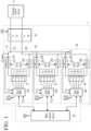
- FIG. 1 is a view showing a battery system according to an embodiment.
- a battery system 1 includes a plurality of battery packs 10 to 30, a main control IC (Main Control Integrated Circuit) 40, and a junction device 50.
- FIG. 1 shows that the number of a plurality of battery packs is three, but the invention is not limited thereto, and the battery system 1 may include four or more battery packs. Also, in FIG. 1 , a plurality of battery packs 10-30 are illustrated as being connected in parallel, but two or more battery packs may be connected in series and a plurality of battery packs that are connected in series may be connected in parallel.
- the external power device 2 may be a load receiving power from the battery system 1 or a charger for charging the battery system 1.
- the external power device 2 may include at least one of an inverter, a DC-DC converter, a motor, an electronic control circuit, an on-board charger (OBC), and a fast charger of a vehicle including the battery system 1.
- OBC on-board charger
- a plurality of battery packs 10 to 30 are connected in parallel to each other, and each of both terminals of a plurality of battery packs 10 to 30 are connected to the junction device 50 through a line 151 and a line 152, respectively.
- the junction device 50 may include a first main relay 51 connected between the line 151 and the external power device 2, and a second main relay 52 connected between the line 152 and the external power device 2.
- the first and second main relays 51 and 52 control the connection between a plurality of battery packs 10 to 30 and the external power device 2, and the main control IC 40 may generate and transmit a relay control signal MRS that controls the operation of the first and second main relays 51 and 52 to the junction device 50.
- the junction device 50 may control the opening and closing of the first and second main relays 51 and 52 according to the relay control signal MRS.
- the junction device 2 is illustrated as including a pair of main relays, but the number of main relay pairs may be determined according to the number of configurations of the external power device 2.
- Each of a plurality of battery packs 10 to 30 includes a plurality of battery cells 11 to 14, 21 to 24, and 31 to 34, a plurality of pack battery management systems 100, 200, and 300, two relays 101, 102, 201, 202, 301, and 302, and current sensors 103, 203, and 303.
- the battery pack battery management system is hereinafter referred to as a battery pack BMS (Battery Management System).
- FIG. 1 shows that each of a plurality of battery packs 10 to 30 includes four battery cells 11 to 14, 21 to 24, and 31 to 34, but this is an example and the invention is not limited thereto.
- each of a plurality of battery packs 10 to 30 is illustrated as including two relays, but this is an example, and the number of relays may be at least one.
- Each of a plurality of pack BMSs 100, 200, and 300 is connected to a plurality of battery cells 11 to 14, 21 to 24, and 31 to 34 to measure a cell voltage of a plurality of battery cells 11 to 14, 21 to 24, and 31 to 34.
- Each of a plurality of pack BMSs 100, 200, and 300 may obtain a voltage (hereinafter, a battery pack voltage), a current (hereinafter, a battery pack current), and a temperature (hereinafter, a temperature of the battery pack) of each of the battery packs 10, 20, and 30.
- Each of a plurality of pack BMSs 100, 200, and 300 may control the charge and discharge of the battery packs 10 to 30 based on the cell voltage, battery pack current, and the like of a plurality of battery cells 11 to 14, 21 to 24, and 31 to 34, and may control and perform the cell balancing operation for a plurality of battery cells 11 to 14, 21 to 24, and 31 to 34.
- a plurality of pack BMSs 100, 200, and 300 may control the opening and closing of each of a plurality of relays 101, 102, 201, 202, 301, and 302 for controlling the charge and discharge of a plurality of battery packs 10 to 30.
- a plurality of pack BMSs 100, 200, and 300 may each generate two driving signals RLS1/RLS2, RLS3/RLS4, and RLS5/RLS6 that control the opening and closing of two relays 101/102, 201/202, and 301/302 to be supplied to two relays 101/102, 201/202, and 301/302.
- the main control IC 40 may receive the cell voltage of a plurality of battery cells 11 to 15, 21 to 25, and 31 to 35, the information for the battery pack voltage, the battery pack current, and the battery pack temperature of the plurality of battery packs 10, 20, and 30 from the plurality of pack BMSs 100, 200, and 300.
- the main control IC 40 may supply a power control signal to a plurality of pack BMSs 100, 200, and 300 for supplying power to the outside, or a charge control signal for the charge of a plurality of battery packs 10, 20, and 30 to a plurality of pack BMSs 100, 200, and 300.
- the main control circuit 40 may perform control necessary for the operation of the battery system 1, and when an abnormal state of the battery system 1 is detected, a protection operation may be started and controlled.
- a plurality of pack BMSs 100, 200, and 300 determine whether a plurality of relays 101/102, 201/202, and 301/302 are stuck-closed.
- the present invention is not limited thereto, and the main control IC 40 determines whether or not the plurality of relays 101/102, 201/202, and 301/302 are stuck-closed based on the cell information received from a plurality of pack BMSs 100, 200, and 300.
- the relay connected to the positive electrode of the battery pack is referred to as a positive relay
- the relay connected to the negative electrode of the battery pack is referred to as a negative relay.
- Each of a plurality of pack BMSs 100, 200, and 300 is connected to both terminals of each of a plurality of positive relays 101, 201, and 301, thereby calculating a voltage difference between both terminals.
- one terminal of each of a plurality of positive relays 101, 201, and 301 is connected to the positive electrode of each of a plurality of battery packs 10, 20, and 30, and the other terminal of each of a plurality of positive relays 101, 201, and 301 is connected to the wiring 151.
- the voltage of one terminal of each of a plurality of positive relays 101, 201, and 301 may be the same as the positive electrode voltage of each battery pack, and the voltage of the other terminal of each of the plurality of positive relays 101, 201, and 301 may be the same as the voltage (hereinafter, a positive link voltage) of the positive link.
- the positive link may be the wiring 151 connecting the positive electrode of the plurality of battery packs 100, 200, and 300 and the external power device 2.
- each of the plurality of pack BMSs 100, 200, and 300 is connected to the positive electrode of each of the plurality of battery packs 100, 200, and 300 the positive electrode voltage of each of the plurality of battery packs 100, 200, and 300 may be measured
- a plurality of pack BMSs 100, 200, and 300 may be connected to the wiring 151 to measure the positive electrode voltage.
- a plurality of pack BMSs 100, 200, and 300 include a switch (not shown) connected to the wiring 151, and the switch may be turned on to measure the positive link voltage.
- Each terminal of a plurality of negative relays 102, 202, and 302 is connected to each negative electrode of a plurality of battery packs 10, 20, and 30, and each of the other terminal a plurality of negative relays 102, 202, and 302 is connected to the wiring 152.
- the voltage of the other terminal of each of the plurality of negative relays 102, 202, and 302 may be the same voltage as the voltage (hereinafter, a negative link voltage) of the negative electrode link.
- the negative link may be the wiring 152 connecting the negative electrodes of a plurality of battery packs 100, 200, and 300 to the external power device 2.
- Each of a plurality of pack BMSs 100, 200, and 300 may be connected to the wiring 152 to measure the negative link voltage.
- a plurality of pack BMSs 100, 200, and 300 include a switch (not shown) connected to the wiring 152, and the switch may be turned on to measure the negative link voltage.
- Each of the plurality of current sensors 103, 203, and 303 may measure the battery pack current and transmit a signal indicating the measured current to each of the plurality of pack BMSs 100, 200, and 300.
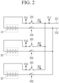
- FIG. 2 is a circuit diagram for explaining a method for determining whether a plurality of positive relays is stuck-closed according to an embodiment.
- FIG. 3 is a flowchart for explaining a method for determining whether a plurality of positive relays is stuck-closed according to an embodiment.
- FIG. 2 shows a plurality of battery packs 100, 200, and 300 , a plurality of positive relays 101, 201, and 301 and a plurality of negative relays 102, 202, and 302 connected to each battery pack for convenience of description.
- FIG. 2 shows the positive relay 101 in a stuck-closed state.
- the closed state of a plurality of negative relays 102, 202, and 302 is shown by a dotted line.
- each of a plurality of pack BMSs 100, 200, and 300 may wake up for a stuck-closed diagnosis (S0).
- a monitoring operation for diagnosing the state of the battery system 1 may be performed by a plurality of pack BMSs 100, 200, and 300.
- a plurality of pack BMSs 100, 200, and 300 may wake up every monitoring period to determine whether each of the plurality of positive relays 101, 201, and 301 is stuck-closed.
- a plurality of pack BMSs 100, 200, and 300 may open and control a plurality of positive relays 101, 201, and 301 and a plurality of negative relays 102, 202, and 302 (S1).
- a plurality of pack BMSs 100, 200, and 300 may calculate both terminals voltage differences of a plurality of positive relays 101, 201, and 301 (S2).
- each of a plurality of pack BMSs 100 measures the voltages VA1, VA2, and VA3 of one terminal of each of a plurality of positive relays 101, 201, and 301 and the positive link voltage VL1, and may calculate an absolute value of the voltage value obtained by subtracting the positive link voltage VL1 from the voltages VA1, VA2, and VA3 of one terminal as both terminals voltage differences of a plurality of positive relays 101, 201, and 301, respectively.
- a plurality of pack BMSs 100, 200, and 300 compare a plurality of the both terminals voltage differences
- a plurality of pack BMSs 100, 200, and 300 end the stuck-closed diagnosis for a plurality of positive relays 101, 201, and 301 (S7).
- the positive link voltage VL1 may be similar to the positive electrode voltage of the battery pack supplied through the stuck-closed positive relay. Since a plurality of battery packs 10, 20, and 30 are operated in a parallel connection state, in the opening control condition of the positive relay and the negative relay, the positive electrode voltages of a plurality of battery packs 10, 20, and 30 may be within a substantially similar range. Therefore, by the stuck-closed positive relay, the both terminals voltage differences
- may all be equal to or greater than the first threshold voltage VTH1.
- each of the plurality of pack BMSs 100, 200, and 300 may be sequentially close to each of the plurality of negative relays 102, 202, and 302 one by one (S4).
- An order in which each of the plurality of pack BMSs 100, 200, and 300 are close to the corresponding negative relays may be controlled by the main control device 40.
- the main control device 40 may close the junction device 50 while measuring a plurality of battery pack currents IB1, IB2, and IB3.
- each of a plurality of negative relays 102, 202, and 302 is sequentially closed one by one.
- Each of a plurality of pack BMSs 100, 200, and 300 compares each of a plurality of battery pack currents IB1, IB2, and IB3 measured by a plurality of current sensors 103, 203, and 303 with a first threshold current ITH1 (S5).
- the pack BMS 100 may determine that the positive relay 101 is stuck-closed (S6).
- a plurality of pack BMSs 200 and 300 terminate the stuck-closed diagnosis, and the pack BMS 100 also terminates the stuck-closed diagnosis after determining the stuck-closed for the positive relay 101 (S7).
- a plurality of pack BMSs 100, 200, and 300 may transmit a stuck-closed diagnosis result to the main control device 40.
- the main control device 40 may control the junction device 50 in an open state when there is a stuck-closed positive relay.
- the main control device 40 may perform an operation to notify the stuck-closed of the positive relay 101.
- information indicating the stuck-closed of the positive relay 101 may be transmitted to a vehicle equipped with the battery system 1 through CAN communication.
- FIG. 4 is a circuit diagram for explaining a method for determining whether a plurality of positive relays are stuck-closed according to an embodiment.
- FIG. 4 unlike FIG. 2 , two positive relays 101 and 301 are shown in a stuck-closed state. Hereinafter, contents overlapping with those described above will be omitted.
- VA3- VL11 of a plurality of positive relays 101, 201, and 301 may be smaller than the first threshold voltage VTH1.
- Each of a plurality of pack BMSs 100, 200, and 300 may sequentially close each of a plurality of negative relays 102, 202, and 302 one by one, and compare each of a plurality of battery pack currents IB1, IB2, and IB3 flowing through each of a plurality of battery packs 10, 20, and 30 with the first threshold current ITH1.
- the pack BMSs 100 and 300 may determine that the positive relays 101 and 103 are stuck-closed.
- the first threshold current ITH1 may be set considering the case where two or more battery positive relays are stuck-closed. For example, when two or more battery positive relays are stuck-closed, the number of the current paths supplied to the vehicle depends on the number of the stuck-closed positive relays. Therefore, compared to the case where one positive relay is stuck-closed, when two or more positive relays are stuck-closed, the battery pack current flowing through the stuck-closed positive relay may be reduced.
- the first threshold current ITH1 should be set in consideration of these points.
- FIG. 5 is a circuit diagram for explaining a method for determining whether a plurality of negative relays are stuck-closed according to an embodiment.
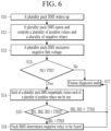
- FIG. 6 is a flowchart for explaining a method for determining whether a plurality of negative relays are stuck-closed according to an embodiment.
- FIG. 5 shows a plurality of battery packs 10, 20, and 30, a plurality of positive relays 101, 201, and 301 and a plurality of negative relays 102, 202, and 302, which are connected to each battery pack for convenience of description.
- the negative relay 102 is shown in a stuck-closed state.
- a closed state of a plurality of positive relays 101, 201, and 301 is shown by a dotted line.
- each of a plurality of pack BMSs 100, 200, and 300 may wake up for the stuck-closed diagnosis (S10).
- a monitoring operation for diagnosing the state of battery system 1 may be performed by a plurality of pack BMSs 100, 200, and 300.
- a plurality of pack BMSs 100, 200, and 300 may wake up every monitoring period to determine whether each of the plurality of negative relays 102, 202, and 302 is stuck-closed.
- a plurality of pack BMSs 100, 200, and 300 may open and control a plurality of positive relays 101, 201, and 301 and a plurality of negative relays 102, 202, and 302 (S11).
- a plurality of pack BMSs 100, 200, and 300 may measure the negative link voltage VL2 (S12).
- a plurality of pack BMSs 100, 200, and 300 may compare the negative link voltage VL2 and the second threshold voltage VHT2 (S13). As a comparison result, when the negative link voltage VL2 is greater than or equal to the second threshold voltage VHT2, a plurality of pack BMSs 100, 200, and 300 end the stuck-closed diagnosis for a plurality of negative relays 102, 202, and 302 (S17).
- each of a plurality of pack BMSs 100, 200, and 300 sequentially closes each of a plurality of positive relays 101, 201, and 301 one by one (S14).
- An order in which each of the plurality of pack BMSs 100, 200, and 300 close the corresponding positive relays may be controlled by the main control device 40.
- the main control device 40 may close the junction device 50 while measuring a plurality of battery pack currents IB1, IB2, and IB3.
- each of a plurality of positive relays 101, 201, and 301 is sequentially closed.
- Each of a plurality of pack BMSs 100, 200, and 300 compares each of a plurality of battery pack currents IB1, IB2, and IB3 measured by each of a plurality of current sensors 103, 203, and 303 with the second threshold current ITH2 (S15).
- the pack BMS 100 may determine that the negative relay 102 is stuck-closed (S16).
- a plurality of pack BMSs 100, 200, and 300 may transmit the stuck-closed diagnosis result to the main control device 40.
- the main control device 40 may control the junction device 50 in an open state when there is the stuck-closed negative relay.
- the main control device 40 may perform the operation to notify the stuck-closed of the negative relay 102.
- the information indicating the stuck-closed of the negative relay 102 may be transmitted to a vehicle equipped with the battery system 1 through CAN communication.
- FIG. 7 is a circuit diagram for explaining a method for determining whether a plurality of negative relays are stuck-closed according to an embodiment.
- FIG. 7 unlike FIG. 5 , shows two negative relays 102 and 302 in a stuck-closed state.
- contents overlapping with those described above are omitted.
- the negative link voltage VL2 is less than the second threshold voltage VTH2.
- Each of a plurality of pack BMSs 100, 200, and 300 may sequentially close one by one each of a plurality of positive relays 101, 201, and 301, and compare each of a plurality of battery pack currents IB1, IB2, and IB3 with a second threshold current ITH2.
- the pack BMSs 100 and 300 may determine that the negative relays 102 and 302 are stuck-closed.
- the second threshold current ITH2 may be set considering the case where two or more battery negative relays are stuck-closed. For example, if two or more battery negative relays are stuck-closed, the number of the current paths supplied to the vehicle depends on the number of stuck-closed negative relays. Therefore, compared to the case where one negative relay is stuck-closed, when two or more negative relays are stuck-closed, the battery pack current flowing through the stuck-closed negative relay may be reduced.
- the second threshold current ITH2 should be set in consideration of these points.
- the embodiments described so far may perform the stuck-closed diagnosis for a plurality of positive relays or a plurality of negative relays.
- the disclosure is not limited thereto, and the embodiment may perform the stuck-closed diagnosis for the positive relay and the negative relay connected to each of a plurality of battery packs.
- FIG. 8 is a circuit diagram for explaining a method for determining whether a plurality of positive relays and a plurality of negative relays are stuck-closed according to an embodiment.
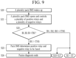
- FIG. 9 is a flowchart for explaining a method for determining whether a plurality of positive relays and a plurality of negative relays are stuck-closed according to an embodiment.
- FIG. 8 shows a plurality of battery packs 10, 20, and 30, and a plurality of positive relays 101, 201, and 301 and a plurality of negative relays 102, 202, and 302, which are connected to each battery pack for convenience of description.
- the positive relay 101 and the negative relay 102 are shown in a stuck-closed state.
- each of a plurality of pack BMSs 100, 200, and 300 may wake up for the stuck-closed diagnosis (S20).
- a monitoring operation for diagnosing the state of battery system 1 may be performed by a plurality of pack BMSs 100, 200, and 300.
- a plurality of pack BMSs 100, 200, and 300 may wake up every monitoring period to determine whether a plurality of positive relays 101, 201, and 301 and a plurality of negative relays 102, 202, and 302 are stuck-closed.
- a plurality of pack BMSs 100, 200, and 300 may open and control a plurality of positive relays 101, 201, and 301 and a plurality of negative relays 102, 202, and 302 (S21).
- Each of a plurality of pack BMSs 100, 200, and 300 compares each of the battery pack currents IB1, IB2, and IB3 flowing through each of a plurality of battery packs 10, 20, and 30 with a third threshold current ITH3 under an open control condition (S22).
- a plurality of battery pack currents IB1, IB2, and IB3 may be measured by a plurality of current sensors 103, 203, and 303, respectively.
- the pack BMS 10 determines that the positive relay 101 and the negative relay 102 are stuck-closed (S23).
- the battery pack currents IB2 and IB3 may be equal to or less than the third threshold current ITH3.
- each of a plurality of pack BMSs 100, 200, and 300 may terminate the stuck-closed diagnosis (S24).
- each of a plurality of pack BMSs 100, 200, and 300 may perform the positive relay diagnosis through the steps S0 to S7 or the negative relay diagnosis through the steps S10 to S17.
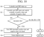
- FIG. 10 is a flowchart showing a variation for an embodiment shown in FIG. 9 .
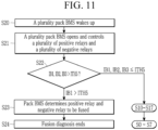
- FIG. 11 is a flowchart showing another variation for an embodiment shown in FIG. 9 .
- each of a plurality of pack BMSs 100, 200, and 300 may perform the negative relay diagnosis (S10 to S17) after performing the positive relay diagnosis (S0 to S7).
- each of a plurality of pack BMSs 100, 200, and 300 may perform the positive relay diagnosis (S0 to S7) after performing the negative relay diagnosis (S10 to S17).
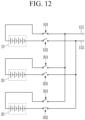
- FIG. 12 is a circuit diagram for explaining a method for determining whether a plurality of positive relays and a plurality of negative relays are stuck-closed according to an embodiment.
- a plurality of pack BMSs 100, 200, and 300 may perform the steps S20 to S23 depending on the method shown in FIG. 9 .
- the circuit shown in FIG. 10 since a plurality of battery pack currents IB1, IB2, and IB3 are all less than the third threshold current ITH3, the corresponding diagnosis is terminated.
- each of a plurality of pack BMSs 100, 200, and 300 may perform the positive relay diagnosis through the steps S0 to S7 and the negative relay diagnosis through the steps S10 to S17. Conversely, each of a plurality of pack BMSs 100, 200, and 300 may perform the negative relay diagnosis through the steps S10 to S17 and the positive relay diagnosis through the steps S0 to S7.
- the pack BMS 100 may determine the stuck-closed of the positive relay 101, and the pack BMS 200 may determine the stuck-closed of the negative relay 302.
- the relay in which the stuck-closed has occurred among a plurality of relays may be accurately diagnosed.
Landscapes
- General Physics & Mathematics (AREA)
- Physics & Mathematics (AREA)
- Engineering & Computer Science (AREA)
- Power Engineering (AREA)
- Chemical & Material Sciences (AREA)
- Electrochemistry (AREA)
- General Chemical & Material Sciences (AREA)
- Chemical Kinetics & Catalysis (AREA)
- Manufacturing & Machinery (AREA)
- Microelectronics & Electronic Packaging (AREA)
- Charge And Discharge Circuits For Batteries Or The Like (AREA)
- Secondary Cells (AREA)
- Testing Electric Properties And Detecting Electric Faults (AREA)
- Protection Of Static Devices (AREA)
Abstract
Description
- This application claims priority to and the benefit of
Korean Patent Application No. 10-2022-0002133 filed in the Korean Intellectual Property Office on January 06, 2022 - The present disclosure relates to a stuck-closed diagnosis method and a battery system using the same.
- In general, during a time of a stuck-closed diagnosis for each of a positive relay connected to a positive electrode of a battery pack and a negative relay connected to a negative electrode of the battery pack, a voltage of the positive electrode of the battery pack and a voltage of a link connected to the positive relay, or the voltage of the negative electrode of the battery pack and the voltage of the link connected to the negative relay, are compared with each other. However, when a plurality of battery packs are connected in parallel, it is difficult to perform the stuck-closed diagnosis for each positive relay and negative relay of a plurality of battery packs in the same manner as above.
- In addition, even if the stuck-closed diagnosis occurs, it's hard to know which battery pack's positive relay or negative relay among a plurality of battery packs has been stuck-closed, and how many battery packs among a plurality of battery packs are connected to the positive relay and the negative relay where the stuck-closed occurred.
- It is intended to provide a method that may accurately diagnose whether or not there is stuck-closed for each of a plurality of relays when a plurality of battery packs is connected in parallel.
- A battery system according to one feature of the present invention may include: a plurality of battery packs; a plurality of positive relays connected between a positive electrode and a positive link of the corresponding battery pack for each of the plurality of packs; a plurality of negative relays connected between a negative electrode and a negative link of the corresponding battery pack for each of the plurality of packs; and a plurality of pack BMSs (Battery Management Systems) connected to the plurality of battery packs. Each of the plurality of pack BMSs, in an opening control condition of the plurality of positive relays and the plurality of negative relays, diagnoses whether the corresponding positive relay is stuck-closed based on the first battery pack current flowing to the corresponding battery pack when the corresponding negative relay is closed when a difference between both terminal voltages of the corresponding positive relay is less than a first threshold voltage.
- Each of the plurality of pack BMSs may determine the corresponding positive relay to be stuck-closed when the first battery pack current is greater than the first threshold current.
- In the opening control condition of the plurality of positive relays and the plurality of negative relays, if the voltage difference between both terminals of at least one of the plurality of positive relays is less than the first threshold voltage, each of the plurality of pack BMSs may measure the battery pack current flowing through each of the plurality of battery packs while sequentially closing each of the plurality of negative relays one by one.
- In the opening control condition of the plurality of positive relays and the plurality of negative relays, when the voltage of the negative link is less than the second threshold voltage, each of the plurality of pack BMSs may diagnose whether or not the corresponding negative relay is stuck-closed based on the second battery pack current flowing through each of the plurality of battery packs when each of the plurality of positive relays is sequentially closed one by one.
- Each of the plurality of pack BMSs may determine the corresponding negative relay to be stuck-closed when the second battery pack current is larger than the second threshold current.
- Each of the plurality of pack BMSs may determine the positive relay and the negative relay connected to the battery pack to which the battery pack current that is larger than the third threshold current among battery pack currents flowing to each of the plurality of battery packs flows to be stuck-closed.
- A battery system according to another feature of the invention may include: a plurality of battery packs; a plurality of positive relays connected between a positive electrode and a positive link of the corresponding battery pack for each of the plurality of packs; a plurality of negative relays connected between a negative electrode and a negative link of the corresponding battery pack for each of the plurality of packs; and a plurality of pack BMSs (Battery Management Systems) connected to the plurality of battery packs. Each of the plurality of pack BMSs, in an opening control condition of the plurality of positive relays and the plurality of negative relays, may diagnose at least one positive relay and at least one negative relay to which at least one battery pack current flows to be stuck-closed when at least one among a plurality of battery pack currents flowing to the plurality of battery packs is larger than a third threshold current.
- Each of a plurality of pack BMSs, in an opening control condition of the plurality of positive relays and the plurality of negative relays, when all of the plurality of battery pack currents are below a third threshold current, may diagnose the stuck-closed of the corresponding positive relay based on the first battery pack current flowing to the corresponding battery pack when the corresponding negative relay is closed, if a difference between both terminal voltages of the corresponding positive relay is less than the first threshold voltage.
- Each of the plurality of pack BMSs, in the opening control condition of the plurality of positive relays and the plurality of negative relays, when all of the plurality of battery pack currents are below the third threshold current, may diagnose whether the corresponding negative relay is stuck-closed based on the second battery pack current flowing to the corresponding battery pack when the corresponding positive relay is closed, if the voltage of the negative link is less than the second threshold voltage.
- In a stuck-closed diagnosis method as a method for diagnosing stuck-closed for a plurality of positive relays connected to positive electrodes of a plurality of battery packs and a plurality of negative relays connected to negative electrodes of the plurality of battery packs, each of a plurality of pack BMSs connected to the plurality of battery packs may perform: comparing a difference between both terminal voltages of each of the plurality of positive relays with a first threshold voltage in an opening control condition of the plurality of positive relays and the plurality of negative relays; sequentially closing the plurality of negative relays one by one when at least one of the differences between the plurality of both terminals voltages is less than the first threshold voltage; comparing a battery pack current flowing through each of the plurality of battery packs with a first threshold current; and determining at least one positive relay through which the at least one current flows to be stuck-closed when at least one of a plurality of battery pack currents of the plurality of battery packs is greater than the first threshold current.
- In a stuck-closed diagnosis method as a method for diagnosing stuck-closed for a plurality of positive relays connected to positive electrodes of a plurality of battery packs and a plurality of negative relays connected to negative electrodes of the plurality of battery packs, each of a plurality of pack BMSs connected to the plurality of battery packs may perform: comparing a voltage of a negative link to which the corresponding negative relay is connected with a threshold voltage in an opening control condition of the plurality of positive relays and the plurality of negative relays; sequentially closing the plurality of positive relays one by one when the voltage of the negative link is less than the second threshold voltage; comparing a battery pack current flowing through each of the plurality of battery packs with a second threshold current; and determining at least one negative relay through which the at least one flows to be stuck-closed when at least one of a plurality of battery pack currents of the plurality of battery packs is greater than the second threshold current.
- The present invention provides the stuck-closed diagnosis method capable of accurately diagnosing the stuck-closed for each of a plurality of relays when a plurality of battery packs are connected in parallel, and the battery system using the same.
-
-
FIG. 1 is a view showing a battery system according to an embodiment. -
FIG. 2 is a circuit diagram for explaining a method for determining whether a plurality of positive relays are stuck-closed according to an embodiment. -
FIG. 3 is a flowchart for explaining a method for determining whether a plurality of positive relays are stuck-closed according to an embodiment. -
FIG. 4 is a circuit diagram for explaining a method for determining whether a plurality of positive relays are stuck-closed according to an embodiment. -
FIG. 5 is a circuit diagram for explaining a method for determining whether a plurality of negative relays are stuck-closed for according to an embodiment. -
FIG. 6 is a flowchart for explaining a method for determining whether a plurality of negative relays are stuck-closed according to an embodiment. -
FIG. 7 is a circuit diagram for explaining a method for determining whether a plurality of negative relays are stuck-closed according to an embodiment. -
FIG. 8 is a circuit diagram for explaining a method for determining whether a plurality of positive relays and a plurality of negative relays are stuck-closed according to an embodiment. -
FIG. 9 is a flowchart for explaining a method for determining whether a plurality of positive relays and a plurality of negative relays are stuck-closed according to an embodiment. -
FIG. 10 is a flowchart showing a variation for an embodiment shown inFIG. 9 . -
FIG. 11 is a flowchart showing another variation for an embodiment shown inFIG. 9 . -
FIG. 12 is a circuit diagram for explaining a method for determining whether a plurality of positive relays and a plurality of negative relays are stuck-closed according to an embodiment. - Embodiments disclosed in the present specification will be described in detail with reference to the accompanying drawings. In the present specification, the same or similar components will be denoted by the same or similar reference numerals, and an overlapped description thereof will be omitted. The terms "module" and "unit" for components used in the following description are used only in order to make the specification easier. Therefore, these terms do not have meanings or roles that distinguish them from each other by themselves. In describing embodiments of the present specification, when it is determined that a detailed description of the well-known art associated with the present invention may obscure the gist of the present invention, it will be omitted. The accompanying drawings are provided only in order to allow embodiments disclosed in the present specification to be easily understood and are not to be interpreted as limiting the spirit disclosed in the present specification, and it is to be understood that the present invention includes all modifications, equivalents, and substitutions without departing from the scope and spirit of the present invention.
- Terms including ordinal numbers such as first, second, and the like will be used only to describe various components, and are not to be interpreted as limiting these components. The terms are only used to differentiate one component from others.
- It is to be understood that when one component is referred to as being "connected" or "coupled" to another component, it may be connected or coupled directly to another component or be connected or coupled to another component with the other component intervening therebetween. On the other hand, it is to be understood that when one component is referred to as being "connected or coupled directly" to another component, it may be connected or coupled to another component without another component intervening therebetween.
- It will be further understood that terms "comprises" or "have" used in the present specification specify the presence of stated features, numerals, steps, operations, components, parts, or a combination thereof, but do not preclude the presence or addition of one or more other features, numerals, steps, operations, components, parts, or a combination thereof.
-
FIG. 1 is a view showing a battery system according to an embodiment. - A
battery system 1 includes a plurality of battery packs 10 to 30, a main control IC (Main Control Integrated Circuit) 40, and ajunction device 50.FIG. 1 shows that the number of a plurality of battery packs is three, but the invention is not limited thereto, and thebattery system 1 may include four or more battery packs. Also, inFIG. 1 , a plurality of battery packs 10-30 are illustrated as being connected in parallel, but two or more battery packs may be connected in series and a plurality of battery packs that are connected in series may be connected in parallel. - The
external power device 2 may be a load receiving power from thebattery system 1 or a charger for charging thebattery system 1. For example, theexternal power device 2 may include at least one of an inverter, a DC-DC converter, a motor, an electronic control circuit, an on-board charger (OBC), and a fast charger of a vehicle including thebattery system 1. - A plurality of battery packs 10 to 30 are connected in parallel to each other, and each of both terminals of a plurality of battery packs 10 to 30 are connected to the
junction device 50 through aline 151 and aline 152, respectively. Thejunction device 50 may include a firstmain relay 51 connected between theline 151 and theexternal power device 2, and a secondmain relay 52 connected between theline 152 and theexternal power device 2. The first and secondmain relays external power device 2, and themain control IC 40 may generate and transmit a relay control signal MRS that controls the operation of the first and secondmain relays junction device 50. Thejunction device 50 may control the opening and closing of the first and secondmain relays FIG. 1 , thejunction device 2 is illustrated as including a pair of main relays, but the number of main relay pairs may be determined according to the number of configurations of theexternal power device 2. - Each of a plurality of
battery packs 10 to 30 includes a plurality ofbattery cells 11 to 14, 21 to 24, and 31 to 34, a plurality of packbattery management systems relays current sensors FIG. 1 shows that each of a plurality ofbattery packs 10 to 30 includes fourbattery cells 11 to 14, 21 to 24, and 31 to 34, but this is an example and the invention is not limited thereto. Also, each of a plurality ofbattery packs 10 to 30 is illustrated as including two relays, but this is an example, and the number of relays may be at least one. - Each of a plurality of
pack BMSs battery cells 11 to 14, 21 to 24, and 31 to 34 to measure a cell voltage of a plurality ofbattery cells 11 to 14, 21 to 24, and 31 to 34. Each of a plurality ofpack BMSs pack BMSs battery cells 11 to 14, 21 to 24, and 31 to 34, and may control and perform the cell balancing operation for a plurality ofbattery cells 11 to 14, 21 to 24, and 31 to 34. - A plurality of
pack BMSs relays pack BMSs relays 101/102, 201/202, and 301/302 to be supplied to tworelays 101/102, 201/202, and 301/302. - The
main control IC 40 may receive the cell voltage of a plurality ofbattery cells 11 to 15, 21 to 25, and 31 to 35, the information for the battery pack voltage, the battery pack current, and the battery pack temperature of the plurality of battery packs 10, 20, and 30 from the plurality ofpack BMSs main control IC 40 may supply a power control signal to a plurality ofpack BMSs pack BMSs main control circuit 40 may perform control necessary for the operation of thebattery system 1, and when an abnormal state of thebattery system 1 is detected, a protection operation may be started and controlled. - In an embodiment, it is described that a plurality of
pack BMSs relays 101/102, 201/202, and 301/302 are stuck-closed. However, the present invention is not limited thereto, and themain control IC 40 determines whether or not the plurality ofrelays 101/102, 201/202, and 301/302 are stuck-closed based on the cell information received from a plurality ofpack BMSs relays 101/102, 201/202, and 301/302, the relay connected to the positive electrode of the battery pack is referred to as a positive relay, and the relay connected to the negative electrode of the battery pack is referred to as a negative relay. - Each of a plurality of
pack BMSs positive relays positive relays positive relays wiring 151. The voltage of one terminal of each of a plurality ofpositive relays positive relays wiring 151 connecting the positive electrode of the plurality of battery packs 100, 200, and 300 and theexternal power device 2. - Since each of the plurality of
pack BMSs
A plurality ofpack BMSs wiring 151 to measure the positive electrode voltage. A plurality ofpack BMSs wiring 151, and the switch may be turned on to measure the positive link voltage. - Each terminal of a plurality of
negative relays negative relays wiring 152. The voltage of the other terminal of each of the plurality ofnegative relays wiring 152 connecting the negative electrodes of a plurality of battery packs 100, 200, and 300 to theexternal power device 2. Each of a plurality ofpack BMSs wiring 152 to measure the negative link voltage. A plurality ofpack BMSs wiring 152, and the switch may be turned on to measure the negative link voltage. - Each of the plurality of
current sensors pack BMSs - Hereinafter, a method for determining whether two relays connected to each of a plurality of battery packs 10, 20, and 30 are stuck-closed will be described with reference to
FIG. 2 to FIG. 10 . -
FIG. 2 is a circuit diagram for explaining a method for determining whether a plurality of positive relays is stuck-closed according to an embodiment. -
FIG. 3 is a flowchart for explaining a method for determining whether a plurality of positive relays is stuck-closed according to an embodiment. -
FIG. 2 shows a plurality of battery packs 100, 200, and 300 , a plurality ofpositive relays negative relays FIG. 2 shows thepositive relay 101 in a stuck-closed state. InFIG. 2 , the closed state of a plurality ofnegative relays - First, each of a plurality of
pack BMSs battery system 1 may be performed by a plurality ofpack BMSs pack BMSs positive relays - A plurality of
pack BMSs positive relays negative relays - A plurality of
pack BMSs positive relays pack BMSs 100 measures the voltages VA1, VA2, and VA3 of one terminal of each of a plurality ofpositive relays positive relays - A plurality of
pack BMSs pack BMSs positive relays - When one of the plurality of
positive relays positive relays positive relays - As a comparison result, when at least one of a plurality of the both terminals voltage differences |VA1-VL1|, |VA2-VL1|, and |VA3-VL1| is less than the first threshold voltage VTH1, each of the plurality of
pack BMSs negative relays pack BMSs main control device 40. Themain control device 40 may close thejunction device 50 while measuring a plurality of battery pack currents IB1, IB2, and IB3. As shown in the dotted line shown inFIG. 2 , each of a plurality ofnegative relays - Each of a plurality of
pack BMSs current sensors - If the battery pack current IB1 among a plurality of battery pack currents IB1, IB2, and IB3 is greater than first threshold current ITH1, the
pack BMS 100 may determine that thepositive relay 101 is stuck-closed (S6). - If the battery pack currents IB2 and IB3 are less than or equal to the first threshold current ITH1, a plurality of
pack BMSs pack BMS 100 also terminates the stuck-closed diagnosis after determining the stuck-closed for the positive relay 101 (S7). - A plurality of
pack BMSs main control device 40. Themain control device 40 may control thejunction device 50 in an open state when there is a stuck-closed positive relay. In addition, themain control device 40 may perform an operation to notify the stuck-closed of thepositive relay 101. For example, information indicating the stuck-closed of thepositive relay 101 may be transmitted to a vehicle equipped with thebattery system 1 through CAN communication. -
FIG. 4 is a circuit diagram for explaining a method for determining whether a plurality of positive relays are stuck-closed according to an embodiment. - In
FIG. 4 , unlikeFIG. 2 , twopositive relays - As shown in
FIG. 4 , since twopositive relays VL 11, |VA2-VL1|, and |VA3- VL11 of a plurality ofpositive relays - Each of a plurality of
pack BMSs negative relays - As a comparison result, among a plurality of battery pack currents IB1, IB2, and IB3, if the battery pack currents IB1 and IB3 are greater than the first threshold current ITH1, the
pack BMSs positive relays - The first threshold current ITH1 may be set considering the case where two or more battery positive relays are stuck-closed. For example, when two or more battery positive relays are stuck-closed, the number of the current paths supplied to the vehicle depends on the number of the stuck-closed positive relays. Therefore, compared to the case where one positive relay is stuck-closed, when two or more positive relays are stuck-closed, the battery pack current flowing through the stuck-closed positive relay may be reduced. The first threshold current ITH1 should be set in consideration of these points.
-
FIG. 5 is a circuit diagram for explaining a method for determining whether a plurality of negative relays are stuck-closed according to an embodiment. -
FIG. 6 is a flowchart for explaining a method for determining whether a plurality of negative relays are stuck-closed according to an embodiment. -
FIG. 5 shows a plurality of battery packs 10, 20, and 30, a plurality ofpositive relays negative relays FIG. 5 , thenegative relay 102 is shown in a stuck-closed state. InFIG. 5 , a closed state of a plurality ofpositive relays - First, each of a plurality of
pack BMSs battery system 1 may be performed by a plurality ofpack BMSs pack BMSs negative relays - A plurality of
pack BMSs positive relays negative relays - A plurality of
pack BMSs - A plurality of
pack BMSs pack BMSs negative relays - As a comparison result, when the negative link voltage VL2 is less than the second threshold voltage VTH2, each of a plurality of
pack BMSs positive relays pack BMSs main control device 40. Themain control device 40 may close thejunction device 50 while measuring a plurality of battery pack currents IB1, IB2, and IB3. Like the dotted line shown inFIG. 5 , each of a plurality ofpositive relays - Each of a plurality of
pack BMSs current sensors - If the battery pack current IB1 among a plurality of battery pack currents IB1, IB2, and IB3 is greater than the second threshold current ITH2, the
pack BMS 100 may determine that thenegative relay 102 is stuck-closed (S16). - When the battery pack currents IB2 and IB3 are less than the second threshold current ITH2, a plurality of
pack BMSs pack BMS 100 determines the stuck-closed for thenegative relay 102 and then ends the stuck-closed diagnosis (S17). - A plurality of
pack BMSs main control device 40. Themain control device 40 may control thejunction device 50 in an open state when there is the stuck-closed negative relay. In addition, themain control device 40 may perform the operation to notify the stuck-closed of thenegative relay 102. For example, the information indicating the stuck-closed of thenegative relay 102 may be transmitted to a vehicle equipped with thebattery system 1 through CAN communication. -
FIG. 7 is a circuit diagram for explaining a method for determining whether a plurality of negative relays are stuck-closed according to an embodiment. -
FIG. 7 , unlikeFIG. 5 , shows twonegative relays - As shown in
FIG. 7 , since the twonegative relays - Each of a plurality of
pack BMSs positive relays - If the battery pack currents IB1 and IB3 among a plurality of battery pack currents IB1, IB2, and IB3 are greater than a fourth threshold current ITH4, the
pack BMSs negative relays - The second threshold current ITH2 may be set considering the case where two or more battery negative relays are stuck-closed. For example, if two or more battery negative relays are stuck-closed, the number of the current paths supplied to the vehicle depends on the number of stuck-closed negative relays. Therefore, compared to the case where one negative relay is stuck-closed, when two or more negative relays are stuck-closed, the battery pack current flowing through the stuck-closed negative relay may be reduced. The second threshold current ITH2 should be set in consideration of these points.
- The embodiments described so far may perform the stuck-closed diagnosis for a plurality of positive relays or a plurality of negative relays. However, the disclosure is not limited thereto, and the embodiment may perform the stuck-closed diagnosis for the positive relay and the negative relay connected to each of a plurality of battery packs.
-
FIG. 8 is a circuit diagram for explaining a method for determining whether a plurality of positive relays and a plurality of negative relays are stuck-closed according to an embodiment. -
FIG. 9 is a flowchart for explaining a method for determining whether a plurality of positive relays and a plurality of negative relays are stuck-closed according to an embodiment. -
FIG. 8 shows a plurality of battery packs 10, 20, and 30, and a plurality ofpositive relays negative relays FIG. 8 , thepositive relay 101 and thenegative relay 102 are shown in a stuck-closed state. - First, each of a plurality of
pack BMSs battery system 1 may be performed by a plurality ofpack BMSs pack BMSs positive relays negative relays - A plurality of
pack BMSs positive relays negative relays - Each of a plurality of
pack BMSs current sensors - As a comparison result of the step S22, if at least one (e.g., IB1) of a plurality of battery pack currents IB1, IB2, and IB3 is greater than the third threshold current ITH3, the
pack BMS 10 determines that thepositive relay 101 and thenegative relay 102 are stuck-closed (S23). In this case, the battery pack currents IB2 and IB3 may be equal to or less than the third threshold current ITH3. After the step S23, each of a plurality ofpack BMSs - As a comparison result of the step S22, when a plurality of battery pack currents IB1, IB2, and IB3 are all less than the third threshold current ITH3, each of a plurality of
pack BMSs -
FIG. 10 is a flowchart showing a variation for an embodiment shown inFIG. 9 . -
FIG. 11 is a flowchart showing another variation for an embodiment shown inFIG. 9 . - In each of
FIG. 10 andFIG. 11 , when all of a plurality of battery pack currents are equal to or less than the third threshold current in the step S22, the subsequent operation is different from the embodiment shown inFIG. 9 . - As shown in
FIG. 10 , each of a plurality ofpack BMSs - Also, as shown in
FIG. 11 , each of a plurality ofpack BMSs -
FIG. 12 is a circuit diagram for explaining a method for determining whether a plurality of positive relays and a plurality of negative relays are stuck-closed according to an embodiment. - As shown in
FIG. 12 , when thepositive relay 101 and thenegative relay 302 are stuck-closed, a plurality ofpack BMSs FIG. 9 . In the circuit shown inFIG. 10 , since a plurality of battery pack currents IB1, IB2, and IB3 are all less than the third threshold current ITH3, the corresponding diagnosis is terminated. - Subsequently, each of a plurality of
pack BMSs pack BMSs - Through this, the
pack BMS 100 may determine the stuck-closed of thepositive relay 101, and thepack BMS 200 may determine the stuck-closed of thenegative relay 302. - Through an embodiment, in the battery system in which a plurality of battery packs are connected in parallel, the relay in which the stuck-closed has occurred among a plurality of relays may be accurately diagnosed.
- While this invention has been described in connection with what is presently considered to be practical embodiments, it is to be understood that the invention is not limited to the disclosed embodiments. On the contrary, it is intended to cover various modifications and equivalent arrangements included within the spirit and scope of the appended claims.
Claims (11)
- A battery system comprising:a plurality of battery packs;a plurality of positive relays connected between a positive electrode and a positive link of the corresponding battery pack for each of the plurality of packs;a plurality of negative relays connected between a negative electrode and a negative link of the corresponding battery pack for each of the plurality of packs; anda plurality of pack BMSs (Battery Management Systems) connected to the plurality of battery packs,wherein each of the plurality of pack BMSs, in an opening control condition of the plurality of positive relays and the plurality of negative relays, diagnoses whether the corresponding positive relay is stuck-closed based on the first battery pack current flowing to the corresponding battery pack when the corresponding negative relay is closed when a difference between both terminals voltages of the corresponding positive relay is less than a first threshold voltage.
- The battery system of claim 1, wherein
each of the plurality of pack BMSs determines the corresponding positive relay to be stuck-closed when the first battery pack current is greater than the first threshold current. - The battery system of claim 1, whereinin the opening control condition of the plurality of positive relays and the plurality of negative relays, if the voltage difference between both terminals of at least one of the plurality of positive relays is less than the first threshold voltage,each of the plurality of pack BMSs measures the battery pack current flowing through each of the plurality of battery packs while sequentially closing each of the plurality of negative relays one by one.
- The battery system of claim 1, whereinin the opening control condition of the plurality of positive relays and the plurality of negative relays, when the voltage of the negative link is less than the second threshold voltage,each of the plurality of pack BMSs diagnoses whether or not the corresponding negative relay is stuck-closed based on the second battery pack current flowing through each of the plurality of battery packs when each of the plurality of positive relays is sequentially closed one by one.
- The battery system of claim 4, wherein
each of the plurality of pack BMSs determines the corresponding negative relay to be stuck-closed when the second battery pack current is larger than the second threshold current. - The battery system of claim 1, wherein
each of the plurality of pack BMSs determines the positive relay and the negative relay connected to the battery pack to which the battery pack current is larger than the third threshold current among battery pack currents flowing to each of the plurality of battery packs flows to be stuck-closed. - A battery system comprising:a plurality of battery packs;a plurality of positive relays connected between a positive electrode and a positive link of the corresponding battery pack for each of the plurality of packs;a plurality of negative relays connected between a negative electrode and a negative link of the corresponding battery pack for each of the plurality of packs; anda plurality of pack BMSs (Battery Management Systems) connected to the plurality of battery packs,wherein each of the plurality of pack BMSs, in an opening control condition of the plurality of positive relays and the plurality of negative relays, diagnoses at least one positive relay and at least one negative relay to which at least one battery pack current flows to be stuck-closed when at least one among a plurality of battery pack currents flowing to the plurality of battery packs is larger than a third threshold current.
- The battery system of claim 7, whereineach of a plurality of pack BMSs,in an opening control condition of the plurality of positive relays and the plurality of negative relays, when all of the plurality of battery pack currents are below a third threshold current,diagnosis the stuck-closed of the corresponding positive relay based on the first battery pack current flowing to the corresponding battery pack when the corresponding negative relay is closed, if a difference between both terminal voltages of the corresponding positive relay is less than the first threshold voltage.
- The battery system of claim 7, whereineach of the plurality of pack BMSs,in the opening control condition of the plurality of positive relays and the plurality of negative relays, when all of the plurality of battery pack currents are below the third threshold current,diagnoses whether the corresponding negative relay is stuck-closed based on the second battery pack current flowing to the corresponding battery pack when the corresponding positive relay is closed, if the voltage of the negative link is less than the second threshold voltage.
- A stuck-closed diagnosis method as a method for diagnosing stuck-closed for a plurality of positive relays connected to positive electrodes of a plurality of battery packs and a plurality of negative relays connected to negative electrodes of the plurality of battery packs,
wherein each of a plurality of pack BMSs connected to the plurality of battery packs performs:comparing a difference between both terminals voltages of each of the plurality of positive relays with a first threshold voltage in an opening control condition of the plurality of positive relays and the plurality of negative relays;sequentially closing the plurality of negative relays one by one when at least one of the differences between the plurality of both terminal voltages is less than the first threshold voltage;comparing a battery pack current flowing through each of the plurality of battery packs with a first threshold current; anddetermining at least one positive relay through which the at least one battery pack current flows to be stuck-closed when at least one of a plurality of battery pack currents of the plurality of battery packs is greater than the first threshold current. - A stuck-closed diagnosis method as a method for diagnosing stuck-closed for a plurality of positive relays connected to positive electrodes of a plurality of battery packs and a plurality of negative relays connected to negative electrodes of the plurality of battery packs,
wherein each of a plurality of pack BMSs connected to the plurality of battery packs performs:comparing a voltage of a negative link to which the corresponding negative relay is connected with a threshold voltage in an opening control condition of the plurality of positive relays and the plurality of negative relays;sequentially closing the plurality of positive relays one by one when the voltage of the negative link is less than the second threshold voltage;comparing a battery pack current flowing through each of the plurality of battery packs with a second threshold current; anddetermining at least one negative relay through which the at least one flows to be stuck-closed when at least one of a plurality of battery pack currents of the plurality of battery packs is greater than the second threshold current.
Applications Claiming Priority (2)
| Application Number | Priority Date | Filing Date | Title |
|---|---|---|---|
| KR1020220002133A KR20230106344A (en) | 2022-01-06 | 2022-01-06 | Stucked diagnosis method and battery system using the same |
| PCT/KR2023/000094 WO2023132604A1 (en) | 2022-01-06 | 2023-01-03 | Stuck-closed diagnosis method and battery system using same |
Publications (3)
| Publication Number | Publication Date |
|---|---|
| EP4425201A1 true EP4425201A1 (en) | 2024-09-04 |
| EP4425201A4 EP4425201A4 (en) | 2025-02-26 |
| EP4425201B1 EP4425201B1 (en) | 2026-03-04 |
Family
ID=87073872
Family Applications (1)
| Application Number | Title | Priority Date | Filing Date |
|---|---|---|---|
| EP23737352.7A Active EP4425201B1 (en) | 2022-01-06 | 2023-01-03 | Stuck-closed diagnosis method and battery system using the same |
Country Status (6)
| Country | Link |
|---|---|
| US (1) | US12584963B2 (en) |
| EP (1) | EP4425201B1 (en) |
| JP (1) | JP7722782B2 (en) |
| KR (1) | KR20230106344A (en) |
| CN (1) | CN118318176A (en) |
| WO (1) | WO2023132604A1 (en) |
Families Citing this family (3)
| Publication number | Priority date | Publication date | Assignee | Title |
|---|---|---|---|---|
| WO2026028446A1 (en) * | 2024-08-02 | 2026-02-05 | 日産自動車株式会社 | Sticking diagnosis method and sticking diagnosis device |
| WO2026028447A1 (en) * | 2024-08-02 | 2026-02-05 | 日産自動車株式会社 | Sticking diagnosis method and sticking diagnosis device |
| WO2026028449A1 (en) * | 2024-08-02 | 2026-02-05 | 日産自動車株式会社 | Sticking diagnosis method and sticking diagnosis device |
Family Cites Families (23)
| Publication number | Priority date | Publication date | Assignee | Title |
|---|---|---|---|---|
| DE69937220T2 (en) * | 1998-03-06 | 2008-07-03 | Matsushita Electric Industrial Co., Ltd., Kadoma | VOLTAGE MEASURING DEVICE WITH FLYING CAPACITOR |
| KR100709841B1 (en) | 2005-11-03 | 2007-04-23 | 삼성에스디아이 주식회사 | Battery pack |
| JP4788461B2 (en) * | 2006-04-24 | 2011-10-05 | トヨタ自動車株式会社 | Power supply control device and relay abnormality detection method |
| JP2010004693A (en) | 2008-06-23 | 2010-01-07 | Toyota Motor Corp | Controller for power circuit and power system with controller thereof |
| KR101255248B1 (en) | 2011-07-04 | 2013-04-16 | 로베르트 보쉬 게엠베하 | Battery management system and control method thereof |
| KR101953121B1 (en) * | 2012-11-14 | 2019-02-28 | 에스케이이노베이션 주식회사 | Apparatus and method for detecting relay welding in battery system |
| US10464507B2 (en) * | 2013-03-07 | 2019-11-05 | Samsung Sdi Co., Ltd. | Battery management system and switching method thereof |
| KR101806996B1 (en) * | 2014-12-26 | 2017-12-08 | 주식회사 엘지화학 | State diagnosis apparatus and method for relay drive circuit |
| KR101712258B1 (en) | 2015-02-24 | 2017-03-03 | 주식회사 엘지화학 | Apparatus and method for detecting welding of relay |
| KR102436418B1 (en) | 2015-07-02 | 2022-08-25 | 삼성에스디아이 주식회사 | Method for Detecting Battery Pack Current |
| JP2017079496A (en) | 2015-10-19 | 2017-04-27 | 三菱自動車工業株式会社 | Contactor failure determination device and contactor failure determination method |
| JP6617023B2 (en) | 2015-12-24 | 2019-12-04 | 株式会社エンビジョンAescジャパン | Relay failure diagnosis method |
| JP6831281B2 (en) | 2017-03-27 | 2021-02-17 | 株式会社デンソーテン | Battery monitoring system and battery monitoring device |
| KR102446969B1 (en) | 2017-06-08 | 2022-09-23 | 엘지이노텍 주식회사 | Method and device for detecting fusion of charging relay in vehicle |
| JP6963358B2 (en) | 2018-03-26 | 2021-11-10 | 株式会社エンビジョンAescジャパン | Power supply |
| KR102433848B1 (en) | 2018-09-12 | 2022-08-17 | 주식회사 엘지에너지솔루션 | Apparatus and method for diagnosing switch |
| KR102779969B1 (en) | 2018-11-02 | 2025-03-12 | 주식회사 엘지에너지솔루션 | Apparatus for diagnosing contactor |
| KR102702762B1 (en) | 2018-12-19 | 2024-09-03 | 주식회사 엘지에너지솔루션 | Appartus and method for diagnosing relay |
| KR102844381B1 (en) | 2019-11-13 | 2025-08-08 | 주식회사 엘지에너지솔루션 | Diagnosing Apparatus for Malfunction of Switch means included in Multi Battery Pack and Method thereof |
| PL3985403T3 (en) | 2019-11-13 | 2025-06-02 | Lg Energy Solution, Ltd. | Apparatus and method for diagnosing failure of switch unit included in multi battery pack |
| KR102785104B1 (en) | 2019-12-20 | 2025-03-21 | 주식회사 엘지에너지솔루션 | Apparatus and method for diagnosing parallel battery relay |
| KR102729158B1 (en) | 2020-06-08 | 2024-11-12 | 주식회사 엘지에너지솔루션 | Relay diagnosis apparatus, relay diagnosis method, battery system, and electric vehicle |
| JP7392755B2 (en) * | 2022-03-24 | 2023-12-06 | いすゞ自動車株式会社 | Sticking diagnosis device and sticking diagnosis method |
-
2022
- 2022-01-06 KR KR1020220002133A patent/KR20230106344A/en active Pending
-
2023
- 2023-01-03 JP JP2024525512A patent/JP7722782B2/en active Active
- 2023-01-03 WO PCT/KR2023/000094 patent/WO2023132604A1/en not_active Ceased
- 2023-01-03 EP EP23737352.7A patent/EP4425201B1/en active Active
- 2023-01-03 US US18/715,244 patent/US12584963B2/en active Active
- 2023-01-03 CN CN202380014773.2A patent/CN118318176A/en active Pending
Also Published As
| Publication number | Publication date |
|---|---|
| US20250027997A1 (en) | 2025-01-23 |
| US12584963B2 (en) | 2026-03-24 |
| JP2024538288A (en) | 2024-10-18 |
| CN118318176A (en) | 2024-07-09 |
| EP4425201A4 (en) | 2025-02-26 |
| KR20230106344A (en) | 2023-07-13 |
| JP7722782B2 (en) | 2025-08-13 |
| EP4425201B1 (en) | 2026-03-04 |
| WO2023132604A1 (en) | 2023-07-13 |
Similar Documents
| Publication | Publication Date | Title |
|---|---|---|
| EP4425201B1 (en) | Stuck-closed diagnosis method and battery system using the same | |
| US10974617B2 (en) | Electric power storage system | |
| EP3933415B1 (en) | Apparatus for estimating insulation resistance and battery system using the same | |
| US9340122B2 (en) | Battery system monitoring apparatus | |
| EP3998491B1 (en) | Apparatus and method for diagnosing insulation resistance measurement circuit | |
| JP5092812B2 (en) | Battery monitoring device and failure diagnosis method | |
| EP4067922A1 (en) | Battery apparatus, battery management system, and method for diagnosing connection status | |
| JP2013084605A (en) | Integrated circuit for battery cell | |
| EP3618218A1 (en) | Power supply system, fault diagnosis method for power supply system, and system control device | |
| JPWO2013024541A1 (en) | Battery monitoring device and battery control device provided with the same | |
| US12429522B2 (en) | Relay diagnosis device and relay diagnosis method | |
| EP4462142B1 (en) | Battery system capable of pack relay diagnosis and vehicle comprising the same | |
| GB2643966A (en) | Lithium ion battery pack and charging system | |
| KR102839450B1 (en) | Battery apparatus and drift fault diagnosis method | |
| EP4332599B1 (en) | External short diagnosis method of preventing melt bonding and battery system where the method is applied | |
| US20250381885A1 (en) | Battery System and Parallel Packs Control Method Using the Same | |
| US20250291002A1 (en) | Abnormality detection system | |
| EP4700407A1 (en) | Battery management system, battery device, and method for diagnosing cell voltage measurement line | |
| US20250170918A1 (en) | Control device |
Legal Events
| Date | Code | Title | Description |
|---|---|---|---|
| STAA | Information on the status of an ep patent application or granted ep patent |
Free format text: STATUS: THE INTERNATIONAL PUBLICATION HAS BEEN MADE |
|
| PUAI | Public reference made under article 153(3) epc to a published international application that has entered the european phase |
Free format text: ORIGINAL CODE: 0009012 |
|
| STAA | Information on the status of an ep patent application or granted ep patent |
Free format text: STATUS: REQUEST FOR EXAMINATION WAS MADE |
|
| 17P | Request for examination filed |
Effective date: 20240529 |
|
| AK | Designated contracting states |
Kind code of ref document: A1 Designated state(s): AL AT BE BG CH CY CZ DE DK EE ES FI FR GB GR HR HU IE IS IT LI LT LU LV MC ME MK MT NL NO PL PT RO RS SE SI SK SM TR |
|
| A4 | Supplementary search report drawn up and despatched |
Effective date: 20250129 |
|
| RIC1 | Information provided on ipc code assigned before grant |
Ipc: G01R 19/10 20060101ALI20250123BHEP Ipc: G01R 19/165 20060101ALI20250123BHEP Ipc: G01R 19/00 20060101ALI20250123BHEP Ipc: G01R 31/327 20060101ALI20250123BHEP Ipc: G01R 31/396 20190101ALI20250123BHEP Ipc: G01R 31/392 20190101AFI20250123BHEP |
|
| DAV | Request for validation of the european patent (deleted) | ||
| DAX | Request for extension of the european patent (deleted) | ||
| GRAP | Despatch of communication of intention to grant a patent |
Free format text: ORIGINAL CODE: EPIDOSNIGR1 |
|
| STAA | Information on the status of an ep patent application or granted ep patent |
Free format text: STATUS: GRANT OF PATENT IS INTENDED |
|
| INTG | Intention to grant announced |
Effective date: 20250605 |
|
| P01 | Opt-out of the competence of the unified patent court (upc) registered |
Free format text: CASE NUMBER: APP_31609/2025 Effective date: 20250701 |
|
| GRAJ | Information related to disapproval of communication of intention to grant by the applicant or resumption of examination proceedings by the epo deleted |
Free format text: ORIGINAL CODE: EPIDOSDIGR1 |
|
| STAA | Information on the status of an ep patent application or granted ep patent |
Free format text: STATUS: REQUEST FOR EXAMINATION WAS MADE |
|
| GRAS | Grant fee paid |
Free format text: ORIGINAL CODE: EPIDOSNIGR3 |
|
| STAA | Information on the status of an ep patent application or granted ep patent |
Free format text: STATUS: GRANT OF PATENT IS INTENDED |
|
| GRAP | Despatch of communication of intention to grant a patent |
Free format text: ORIGINAL CODE: EPIDOSNIGR1 |
|
| GRAJ | Information related to disapproval of communication of intention to grant by the applicant or resumption of examination proceedings by the epo deleted |
Free format text: ORIGINAL CODE: EPIDOSDIGR1 |
|
| STAA | Information on the status of an ep patent application or granted ep patent |
Free format text: STATUS: REQUEST FOR EXAMINATION WAS MADE |
|
| INTC | Intention to grant announced (deleted) | ||
| GRAS | Grant fee paid |
Free format text: ORIGINAL CODE: EPIDOSNIGR3 |
|
| STAA | Information on the status of an ep patent application or granted ep patent |
Free format text: STATUS: GRANT OF PATENT IS INTENDED |
|
| GRAP | Despatch of communication of intention to grant a patent |
Free format text: ORIGINAL CODE: EPIDOSNIGR1 |
|
| INTG | Intention to grant announced |
Effective date: 20251014 |
|
| INTC | Intention to grant announced (deleted) | ||
| INTG | Intention to grant announced |
Effective date: 20251113 |
|
| GRAA | (expected) grant |
Free format text: ORIGINAL CODE: 0009210 |
|
| STAA | Information on the status of an ep patent application or granted ep patent |
Free format text: STATUS: THE PATENT HAS BEEN GRANTED |
|
| AK | Designated contracting states |
Kind code of ref document: B1 Designated state(s): AL AT BE BG CH CY CZ DE DK EE ES FI FR GB GR HR HU IE IS IT LI LT LU LV MC ME MK MT NL NO PL PT RO RS SE SI SK SM TR |
|
| REG | Reference to a national code |
Ref country code: CH Ref legal event code: F10 Free format text: ST27 STATUS EVENT CODE: U-0-0-F10-F00 (AS PROVIDED BY THE NATIONAL OFFICE) Effective date: 20260304 Ref country code: GB Ref legal event code: FG4D |
|
| REG | Reference to a national code |
Ref country code: IE Ref legal event code: FG4D |
|
| REG | Reference to a national code |
Ref country code: DE Ref legal event code: R096 Ref document number: 602023013081 Country of ref document: DE |
|
| REG | Reference to a national code |
Ref country code: ES Ref legal event code: FG2A Ref document number: 3064995 Country of ref document: ES Kind code of ref document: T3 Effective date: 20260430 |