EP4425186A1 - Micro flow passage device - Google Patents
Micro flow passage device Download PDFInfo
- Publication number
- EP4425186A1 EP4425186A1 EP22886901.2A EP22886901A EP4425186A1 EP 4425186 A1 EP4425186 A1 EP 4425186A1 EP 22886901 A EP22886901 A EP 22886901A EP 4425186 A1 EP4425186 A1 EP 4425186A1
- Authority
- EP
- European Patent Office
- Prior art keywords
- channel system
- holder
- chip body
- connection port
- lid member
- Prior art date
- Legal status (The legal status is an assumption and is not a legal conclusion. Google has not performed a legal analysis and makes no representation as to the accuracy of the status listed.)
- Withdrawn
Links
Images


Classifications
-
- G—PHYSICS
- G01—MEASURING; TESTING
- G01N—INVESTIGATING OR ANALYSING MATERIALS BY DETERMINING THEIR CHEMICAL OR PHYSICAL PROPERTIES
- G01N35/00—Automatic analysis not limited to methods or materials provided for in any single one of groups G01N1/00 - G01N33/00; Handling materials therefor
-
- B—PERFORMING OPERATIONS; TRANSPORTING
- B01—PHYSICAL OR CHEMICAL PROCESSES OR APPARATUS IN GENERAL
- B01L—CHEMICAL OR PHYSICAL LABORATORY APPARATUS FOR GENERAL USE
- B01L3/00—Containers or dishes for laboratory use, e.g. laboratory glassware; Droppers
- B01L3/50—Containers for the purpose of retaining a material to be analysed, e.g. test tubes
- B01L3/502—Containers for the purpose of retaining a material to be analysed, e.g. test tubes with fluid transport, e.g. in multi-compartment structures
- B01L3/5027—Containers for the purpose of retaining a material to be analysed, e.g. test tubes with fluid transport, e.g. in multi-compartment structures by integrated microfluidic structures, i.e. dimensions of channels and chambers are such that surface tension forces are important, e.g. lab-on-a-chip
- B01L3/502715—Containers for the purpose of retaining a material to be analysed, e.g. test tubes with fluid transport, e.g. in multi-compartment structures by integrated microfluidic structures, i.e. dimensions of channels and chambers are such that surface tension forces are important, e.g. lab-on-a-chip characterised by interfacing components, e.g. fluidic, electrical, optical or mechanical interfaces
-
- G—PHYSICS
- G01—MEASURING; TESTING
- G01N—INVESTIGATING OR ANALYSING MATERIALS BY DETERMINING THEIR CHEMICAL OR PHYSICAL PROPERTIES
- G01N35/00—Automatic analysis not limited to methods or materials provided for in any single one of groups G01N1/00 - G01N33/00; Handling materials therefor
- G01N35/02—Automatic analysis not limited to methods or materials provided for in any single one of groups G01N1/00 - G01N33/00; Handling materials therefor using a plurality of sample containers moved by a conveyor system past one or more treatment or analysis stations
-
- B—PERFORMING OPERATIONS; TRANSPORTING
- B01—PHYSICAL OR CHEMICAL PROCESSES OR APPARATUS IN GENERAL
- B01L—CHEMICAL OR PHYSICAL LABORATORY APPARATUS FOR GENERAL USE
- B01L2200/00—Solutions for specific problems relating to chemical or physical laboratory apparatus
- B01L2200/10—Integrating sample preparation and analysis in single entity, e.g. lab-on-a-chip concept
-
- B—PERFORMING OPERATIONS; TRANSPORTING
- B01—PHYSICAL OR CHEMICAL PROCESSES OR APPARATUS IN GENERAL
- B01L—CHEMICAL OR PHYSICAL LABORATORY APPARATUS FOR GENERAL USE
- B01L2200/00—Solutions for specific problems relating to chemical or physical laboratory apparatus
- B01L2200/16—Reagents, handling or storing thereof
Definitions
- the present invention relates to a microchannel device.
- microchannel devices equipped with microchannels are widely used for blood tests, genetic tests, and other tests as well as biochemical analysis to control liquid delivery of various specimens, samples, or the like, and to control their reactions.
- the microchannel device for such testing and analysis has a channel structure that allows a plurality of liquids to be combined and mixed with each other.
- PTL 1 discloses a microchip that includes a recess for containing a liquid reagent, and a sealing film having an end thereof drawn out of the microchip.
- the recess is formed in a bottom surface of a groove.
- the sealing film is adhered to the bottom surface of the groove so as to cover an opening of the recess entirely.
- PTL 2 discloses a test device for performing liquid transfer and reactions.
- the test device includes a pipette tip containing a liquid reagent, a housing having a plunger assembly, and a reaction chamber.
- the housing is configured to be engageable with the reaction chamber. When the housing is engaged with the reaction chamber, the pipette tip pierces a seal on a microtube that encapsulates a dry reagent. With the movement of the pipette tip, the test device initiates a reaction.
- the test device disclosed in PTL 2 accommodates the liquid reagent and the dry reagent separately in individual containers and combines these reagents in use. It is hence possible to manage storage of the liquid reagent in a non-dry state and storage of the dry reagent in a dry state.
- the test device that includes a plurality of components is inevitably large and has a risk of losing the components that are stored separately. These disadvantages result in low usability.
- the present invention is made in view of the above-mentioned disadvantages, and aims to provide a microchannel device that can hold both a liquid which prefers a non-dry state and a dry reagent which prefers a dry state, that can maintain the preferable storage conditions, that can shut off the liquid and the dry reagent from each other, and that can combine them together.
- the present invention for achieving the above-mentioned object provides a microchannel device that includes: a chip body having a microchannel; and a lid member attachable to the chip body, wherein the microchannel includes a first channel system having a liquid holder that encapsulates a liquid, and a second channel system having a dry reagent holder that encapsulates a dry reagent, with the first channel system and the second channel system being shut off from each other in the chip body, wherein the lid member has a first groove formed in a contact surface to face the chip body, and wherein the lid member, when attached to the chip body, allows the first channel system and the second channel system to communicate with each other via the first groove.
- the microchannel device that includes the above-mentioned specified matter can shut off the liquid holder and the dry reagent holder from each other, and can thereby store the liquid in a non-dry state and store the dry reagent in a dry state. In use, the microchannel device can easily allow the liquid holder and the dry reagent holder to communicate with each other.
- the chip body has a contact surface to face the lid member, a first connection port that constitutes an end of the first channel system, and a second connection port that constitutes an end of the second channel system, with the first connection port and the second connection port being open to the contact surface to face the lid member.
- the first groove has a recessed groove-like shape configured to connect the first connection port to the second connection port.
- the first connection port and the second connection port are sealed by a sealing member that is adhesive to and removable from the chip body.
- the lid member is attached to the chip body from which the sealing member has been removed.
- the second channel system has a desiccant holder that encapsulates a desiccant and that communicates with the dry reagent holder.
- the lid member when attached, shuts off the communication between the dry reagent holder and the desiccant holder.
- the lid member preferably has a protrusion formed on the contact surface to face the chip body;
- the chip body preferably has a recessed communication part that is formed in a contact surface to face the lid member and that communicates with the dry reagent holder and the desiccant holder; and the protrusion, when fitting in the communication part, preferably shuts off the communication.
- the microchannel device of the above configuration may further include a constricted part that shows a high flow resistance and that is provided between the dry reagent holder and the desiccant holder.
- the microchannel further includes a third channel system provided downstream of the dry reagent holder in the second channel system that is provided downstream of the first channel system.
- the third channel system and the second channel system are shut off from each other in the chip body.
- the lid member has a recessed second groove formed in the contact surface to face the chip body.
- the lid member is configured, when attached to the chip body, to allow the third channel system and the second channel system to communicate with each other via the second groove.
- the third channel system may be configured to communicate with the second channel system by being connected to the second channel system between the dry reagent holder and the desiccant holder.
- the present invention can shut off the liquid holder encapsulating a liquid and the dry reagent holder encapsulating a dry reagent from each other, and can thereby store the liquid in a non-dry state and store the dry reagent in a dry state.
- the present invention can combine the liquid and the dry reagent with each other in a simple manner.
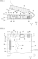
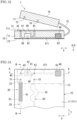
- Fig. 1 is a sectional view schematically showing a microchannel device 1 according to Embodiment 1 of the present invention.
- Fig. 2 is a plan view showing a main part of a chip body 10 of the microchannel device 1.
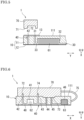
- Fig. 3 and Fig. 4 showing the chip body 10 of the microchannel device 1, are sectional views taken along the line A-A in Fig. 2 and the line B-B in Fig. 2 , respectively.
- the microchannel device 1 is a device for testing or analysis, and has the chip body 10 and a lid member 70 to be attached to the chip body 10, as shown in Fig. 1 and Fig. 2 .
- the microchannel device 1 is configured to mix and deliver, for example, a liquid reagent 61 and a dry reagent 62 encapsulated in the chip body 10, for implementation of a desired process.
- the chip body 10 has a rectangular plate-like shape. As shown in Fig. 3 and Fig. 4 , the chip body 10 includes a first substrate 11 and a second substrate 12. In the illustrated Embodiment, the second substrate 12 is laminated and integrally joined on a bottom surface of the first substrate 11.
- the first substrate 11 and the second substrate 12 can be formed by injection molding of a synthetic resin or may be formed by lamination of a plurality of synthetic resin sheets.
- the overall shape of the chip body 10 is not limited to a rectangular plate-like shape, but may be a disc shape, a sector shape, or any other shape.
- the directions of components of the microchannel device 1 are based on X and Y directions that are orthogonal to each other as shown in Fig. 2 . These directions are specified merely for convenience of description, and are not intended to limit the orientation or other conditions for use of the microchannel chip 1.
- the first substrate 11 of the chip body 10 is provided with a fine channel, a microchannel 20.
- the microchannel 20 includes a first channel system 30 extending in the Y direction, a second channel system 40 extending in the X direction that crosses the first channel system 30, and a third channel system 50 extending in the Y direction that crosses the second channel system 40.
- the first channel system 30 is a channel that delivers, for example, a liquid injected from a liquid introduction port or the like provided further upstream.
- the first channel system 30 is provided with a liquid holder 32 that encapsulates the liquid reagent 61.
- the liquid reagent 61 is liquid at room temperature, and is preferably stored in a non-dry state.
- the liquid holder 32 has a constricted structure, with an upstream channel thereto and a downstream channel therefrom being constricted.
- the channel cross section of, for example, a downstream channel 33 communicating with a downstream side of the liquid holder 32 is smaller than that of the liquid holder 32.
- the downstream channel 33 communicates with a first connection port 31 that opens to a top surface 111 of the first substrate 11, as shown in Fig. 4 .
- the first connection port 31 constitutes a downstream end of the first channel system 30.
- the second channel system 40 has, at an upstream end thereof, a second connection port 42 that opens to the top surface 111 of the first substrate 11.
- the second connection port 42 is aligned on a Y-direction extension of the first connection port 31.
- the second channel system 40 further has an upstream channel 48 communicating with the second connection port 42, and a dry reagent holder 41 encapsulating the dry reagent 62 and communicating with the upstream channel 48.
- the dry reagent holder 41 also has a constricted structure and can stably hold the dry reagent 62 inside.
- the dry reagent 62 is preferably stored in a dry state at room temperature.
- the dry reagent 62 is a beaded enzyme or a beaded reagent mixture that can be kept under ambient temperature.
- the dry reagent 62 is activated on contact with the liquid reagent 61.
- the second channel system 40 is provided with a desiccant holder 46 encapsulating a desiccant and communicating with the dry reagent holder 41.
- This configuration keeps the dry reagent 62 in a dry state.
- the desiccant holder 46 is positioned at a downstream end of the second channel system 40.
- a communication part 47 provided between the dry reagent holder 41 and the desiccant holder 46, allows selection of a communicating state and a shut-off state therebetween.
- the communication part 47 is formed as a recess in the top surface 111 of the first substrate 11 of the chip body 10.
- a fourth connection port 44 communicating with the dry reagent holder 41, and a fifth connection port 45 communicating with the desiccant holder 46 are open to the communication part 47.
- a cover tape 13 is provided on the top surface 111 of the chip body 10, as an adhesive/removable sealing member.
- the cover tape 13 serves to seal the second connection port 42 and the third connection port 43 that are provided in the second channel system 40 and open to the top surface 111 of the chip body 10. With the communication part 47 being covered by the cover tape 13, the fourth connection port 44 and the fifth connection port 45 are allowed to communicate with each other.
- the cover tape 13 may be a highly chemical-resistant, easily adhesive/peelable tape such as an aluminum tape, etc.
- the second channel system 40 allows the dry reagent holder 41 and the desiccant holder 46 to communicate with each other via the communication part 47 as shown in Fig. 1 , and establishes a closed channel by being shut off from the first channel system 30 and the third channel system 50.
- the dry reagent 62 encapsulated in the dry reagent holder 41 is kept in a preferable dry state by a desiccant 63.
- the third channel system 50 has, at an upstream end thereof, a sixth connection port 51 that opens to the top surface 111 of the first substrate 11.
- the third channel system 50 is communicably provided downstream of the dry reagent holder 41 in the second channel system 40 that is provided downstream of the first channel system 30.
- the sixth connection port 51 is aligned on a Y-direction extension of the third connection port 43 in the second channel system 40.
- the third channel system 50 includes a mixing channel 52 that communicates with the sixth connection port 51.
- the mixing channel 52 includes a plurality of widened portions having a widened channel cross section. Liquids mixed in the mixing channel 52 are delivered to a downstream side of the mixing channel 52.
- the cover tape 13 of the chip body 10 is large enough to cover the first connection port 31 in the first channel system 30; the second connection port 42, the third connection port 43, and the communication part 47 in the second channel system 40; and the sixth connection port 51 in the third channel system 50.
- the cover tape 13 as a sealing member, adhering to the chip body 10, the first channel system 30 and the second channel system 40 are shut off from each other.
- the second channel system 40 and the third channel system 50 are shut off from each other, and the first channel system 30 and the third channel system 50 are shut off from each other.
- the top surface 111 of the chip body 10 serves as a contact surface to face the lid member 70.
- the lid member 70 is joined with the chip body 10 via a joint 75, and is attachable to the chip body 10.
- the lid member 70 has a contact surface 71 as a bottom surface thereof.
- the contact surface 71 is a surface to make contact with the first substrate 11 (the top surface 111) of the chip body 10.
- the lid member 70 is large enough to cover the first connection port 31 in the first channel system 30; the second connection port 42, the third connection port 43, and the communication part 47 in the second channel system 40; and the sixth connection port 51 in the third channel system 50.
- the lid member 70 is preferably made of an elastic or viscous material including a silicone-based rubber or a synthetic resin such as an elastomer.
- the contact surface 71 of the lid member 70 has a first groove 72 and a second groove 74.
- the first groove 72 and the second groove 74 extend parallel to the Y direction and do not cross each other.
- the first groove 72 and the second groove 74 have a common cross section, which is a fine groove-like cross section similar to the microchannel 20 in the chip body 10.
- Fig. 5 is a sectional view schematically showing the microchannel device 1, taken along the Y direction.
- the first groove 72 has a recessed groove-like shape, and is arranged in a corresponding manner between the first connection port 31 and the second connection port 42 in the chip body 10. As shown in Fig. 2 , the first groove 72 extends linearly over the first connection port 31 and the second connection port 42, both of which are aligned on the same line extending in the Y direction.
- the second groove 74 has a recessed groove-like shape, as shown in Fig. 1 , and is arranged in a corresponding manner between the third connection port 43 and the sixth connection port 51 in the chip body 10.
- the second groove 74 extends linearly over the third connection port 43 and the sixth connection port 51, both of which are aligned on the same line extending in the Y direction.
- the lid member 70 further has a protrusion 73 that protrudes downwardly from the contact surface 71.
- the position of the protrusion 73 corresponds to that of the recessed communication part 47 formed in the chip body 10.
- a projecting shape of the protrusion 73 corresponds to the shape of the communication part 47 in the chip body 10.
- Fig. 6 is a sectional view taken along the X direction, with the lid member 70 attached to the chip body 10.
- Fig. 7 is a sectional view taken along the Y direction, with the lid member 70 attached to the chip body 10.
- Fig. 8 is a plan view for explaining the microchannel device 1 in use.
- the lid member 70 is attached to the chip body 10 from which the cover tape 13 has been removed from the top surface 111. With the lid member 70 attached to the chip body 10, the first groove 72 in the lid member 70 connects the first connection port 31 to the second connection port 42 in the Y direction, as shown in Fig. 8 .
- the first channel system 30 and the second channel system 40 communicate with each other, as shown in Fig. 7 , via the first groove 72 in the lid member 70.
- the second groove 74 in the lid member 70 connects the third connection port 43 in the second channel system 40 to the sixth connection port 51 in the third channel system 50 in the Y direction.
- the second channel system 40 and the third channel system 50 thus communicate with each other via the second groove 74.
- the protrusion 73 of the lid member 70 fits in the recessed communication part 47 that communicates with the dry reagent holder 41 and the desiccant holder 46.
- the protrusion 73 tightly contacts and seals the fourth connection port 44 and the fifth connection port 45.
- the protrusion 73 shuts off the communication between the dry reagent holder 41 and the desiccant holder 46.
- the thus configured microchannel device 1 allows communication between the liquid holder 32 in the first channel system 30 and the dry reagent holder 41 in the second channel system 40, and thereby allows the liquid reagent 61 in the liquid holder 32 to be combined with the dry reagent 62.
- the liquid reagent 61 flows out of the liquid holder 32, flows through the first connection port 31 to the first groove 72 in the lid member 70, and flows through the second connection port 42 in the second channel system 40 into the dry reagent holder 41, where the liquid reagent 61 contacts and combines with the dry reagent 62.
- the liquid reagent 61 and the dry reagent 62 flow further downstream through the third connection port 43 to the second groove 74 in the lid member 70, flow through the sixth connection port 51 in the third channel system 50, and flow into the mixing channel 52, where the liquid reagent 61 and the dry reagent 62 can mix with each other while flowing.
- the protrusion 73 of the lid member 70 closes the fourth connection port 44 and the fifth connection port 45, and shuts off the communication between the dry reagent holder 41 and the desiccant holder 46. Accordingly, the liquid reagent 61 and the dry reagent 62, as combined, can be led to the third channel system 50.
- the thus configured microchannel device 1 can store the liquid reagent 61 and the dry reagent 62 in the chip body 10 at room temperature, with suitably holding the liquid reagent 61 in a non-dry state in the liquid holder 32 and suitably holding the dry reagent 62 in a dry state in the dry reagent holder 41.
- the operation for using the microchannel device 1 is so simple as to remove the cover tape 13 from the chip body 10 and to attach the lid member 70 to the chip body 10. This simple operation allows the liquid holder 32 and the dry reagent holder 41 to communicate with each other easily, allows the liquid reagent 61 to combine with the dry reagent 62, and thereby enables quick implementation of a test or the like.
- the microchannel device 1 can be formed in a simple structure, at a reduced production cost, in a smaller size.
- the chip body 10 and the lid member 70 are not necessarily joined by the joint 75 but may be provided otherwise.
- the lid member 70 may be provided in advance on the apparatus side of an analytical instrument or the like to which the chip body 10 is attached.
- the linear arrangement of the first channel system 30, the second channel system 40, and the third channel system 50 in the X direction or the Y direction is presented merely as an example of the overall arrangement.
- each of the channel systems may have any shape and any cross section such as a rectangular cross section or a circular cross section.
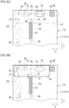
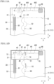
- Fig. 9A is a plan view schematically showing a main part of a chip body 10 of a microchannel device 1 according to Embodiment 2 of the present invention.
- Fig. 9B is a plan view for explaining the microchannel device 1 in use.
- Embodiments 2 to 5 to be described below are common to Embodiment 1 as to the basic configurations of the microchannel device 1. Hence, the following description will detail characteristic configurations of each Embodiment, and will omit the description of the other configurations by sharing the reference signs used in Embodiment 1, etc.
- the layout of the first channel system 30, the second channel system 40, and the third channel system 50 is not limited to the one described in Embodiment 1.
- the third channel system 50 is communicably arranged between the dry reagent holder 41 and the desiccant holder 46 in the second channel system 40.
- the first channel system 30 is communicably arranged between the dry reagent holder 41 and the desiccant holder 46.
- the second connection port 42 in the second channel system 40 is provided between the dry reagent holder 41 and the fourth connection port 44 that opens to the communication part 47.
- the first connection port 31 in the first channel system 30 is aligned on a Y-direction extension of the second connection port 42.
- the third connection port 43 in the second channel system 40 is provided on one side of the dry reagent holder 41 that is a side not facing the desiccant holder 46 and that is an outer side of the chip body 10 in the X direction.
- the sixth connection port 51 in the third channel system 50 is aligned on a Y-direction extension of the third connection port 43.
- the second connection port 42 provided between the dry reagent holder 41 and the desiccant holder 46 is on the upstream side in the second channel system 40.
- Fig. 9B shows the state where the lid member 70 is attached to the chip body 10 from which the cover tape 13 has been removed.
- the protrusion 73 of the lid member 70 fits in the communication part 47, and shuts off the communication between the dry reagent holder 41 and the desiccant holder 46.
- the first connection port 31 in the first channel system 30 communicates with the second connection port 42 in the second channel system 40 via the first groove 72 in the lid member 70.
- the third connection port 43 in the second channel system 40 communicates with the sixth connection port 51 in the third channel system 50 via the second groove 74 in the lid member 70.
- the microchannel device 1 can also store the liquid reagent 61 and the dry reagent 62 in the chip body 10 at room temperature, with suitably holding the liquid reagent 61 in a non-dry state in the liquid holder 32 and suitably holding the dry reagent 62 in a dry state in the dry reagent holder 41.
- the operation for using the microchannel device 1 is so simple as to remove the cover tape 13 and to attach the lid member 70 to the chip body 10. This simple operation allows the liquid reagent 61 to combine with the dry reagent 62.
- Fig. 10A is a plan view schematically showing a main part of a chip body 10 of a microchannel device 1 according to Embodiment 3 of the present invention.
- Fig. 10B is a plan view for explaining the microchannel device 1 in use.
- the third channel system 50 is arranged to communicate with the second channel system 40 via the second groove 74 in the lid member 70.
- the third channel system 50 may be arranged to communicate with the second channel system 40, as described in this Embodiment.
- the third channel system 50 is connected to the second channel system 40 between the dry reagent holder 41 and the desiccant holder 46.
- an upstream channel 53 extends upstream of the mixing channel 52 in the third channel system 50, and communicates with the second channel system 40 between the dry reagent holder 41 and the communication part 47.
- the second channel system 40 does not have the third connection port 43, and the lid member 70 does not have the second groove 74.
- the lid member 70 is attached to the chip body 10 from which the cover tape 13 has been removed, the protrusion 73 of the lid member 70 fits in the communication part 47, and shuts off the communication between the dry reagent holder 41 and the desiccant holder 46.
- the first connection port 31 in the first channel system 30 communicates with the second connection port 42 in the second channel system 40 via the first groove 72 in the lid member 70.
- the channels from the liquid holder 32 in the first channel system 30, through the dry reagent holder 41 in the second channel system 40, to the mixing channel 52 in the third channel system 50 are connected and communicate with each other.
- the microchannel device 1 according to Embodiment 3 can also store the liquid reagent 61 and the dry reagent 62 in the chip body 10 at room temperature, with suitably holding the liquid reagent 61 in a non-dry state in the liquid holder 32 and suitably holding the dry reagent 62 in a dry state in the dry reagent holder 41.
- the operation for using the microchannel device 1 is so simple as to remove the cover tape 13 and to attach the lid member 70 to the chip body 10. This simple operation allows the liquid reagent 61 to combine with the dry reagent 62. Additionally, the microchannel device 1 can be made simpler by omitting the second groove 74 in the lid member 70.
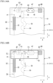
- Fig. 11A is a plan view schematically showing a main part of a chip body 10 of a microchannel device 1 according to Embodiment 4 of the present invention.
- Fig. 11B is a plan view for explaining the microchannel device 1 in use.
- the second channel system 40 includes the recessed communication part 47 between the dry reagent holder 41 and the desiccant holder 46, and the protrusion 73 of the lid member 70 fits in the communication part 47 and thereby shuts off the communication between the dry reagent holder 41 and the desiccant holder 46.
- a constricted part 49 that shows a high flow resistance is provided between the dry reagent holder 41 and the desiccant holder 46.
- the second channel system 40 includes the constricted part 49 on the downstream side (the third connection port 43 side) of the dry reagent holder 41.
- the constricted part 49 has a constricted channel cross section.
- the cross-sectional area of the constricted part 49 taken orthogonally to the X direction that is a liquid delivery direction, is smaller than that of an upstream channel 491 of the constricted part 49 and smaller than that of a downstream channel 492 between the constricted part 49 and the desiccant holder 46.
- This configuration ensures the communication between the dry reagent holder 41 and the desiccant holder 46 to keep the dry reagent 62 in a dry state.
- this configuration increases the flow resistance from the upstream channel 491 toward the constricted part 49 to prevent entry of the liquid reagent 61 or the like.
- the lid member 70 does not have the protrusion 73.
- Fig. 11B shows the state where the lid member 70 is attached to the chip body 10 from which the cover tape 13 has been removed.
- the first connection port 31 in the first channel system 30 communicates with the second connection port 42 in the second channel system 40 via the first groove 72 in the lid member 70
- the third connection port 43 in the second channel system 40 communicates with the sixth connection port 51 in the third channel system 50 via the second groove 74 in the lid member 70.
- the channels from the liquid holder 32 in the first channel system 30, through the dry reagent holder 41 in the second channel system 40, to the mixing channel 52 in the third channel system 50 are connected and communicate with each other.
- the microchannel device 1 according to Embodiment 4 can also store the liquid reagent 61 and the dry reagent 62 in the chip body 10 at room temperature, with suitably holding the liquid reagent 61 in a non-dry state in the liquid holder 32 and suitably holding the dry reagent 62 in a dry state in the dry reagent holder 41.
- the operation for using the microchannel device 1 is so simple as to remove the cover tape 13 and to attach the lid member 70 to the chip body 10. This simple operation allows the liquid reagent 61 to combine with the dry reagent 62.
- the microchannel device 1 can be made simpler by omitting the protrusion 73 in the lid member 70 and omitting the fourth connection port 44, the fifth connection port 45, and the communication part 47 in the chip body 10.
- Fig. 12 is a sectional view schematically showing a microchannel device 1 according to Embodiment 5 of the present invention.
- Fig. 13 is a plan view showing a main part of a chip body 10 of the microchannel device 1.
- the microchannel device 1 can adopt various configurations between the dry reagent holder 41 and the desiccant holder 46.
- the recessed communication part 47 is provided between the dry reagent holder 41 and the desiccant holder 46, and the protrusion 73 of the lid member 70 shuts off the communication between the dry reagent holder 41 and the desiccant holder 46.
- the constricted part 49 that shows a high flow resistance is provided as a constriction between the dry reagent holder 41 and the desiccant holder 46.
- the microchannel device 1 does not necessarily adopt the above-mentioned shuttable or constricted configuration between the dry reagent holder 41 and the desiccant holder 46 in the second channel system 40.
- the dry reagent holder 41 and the desiccant holder 46 may be communicable without constriction or the like.
- the microchannel device 1 has a downstream channel 471 in the second channel system 40, and the dry reagent holder 41 and the desiccant holder 46 communicate with each other via the downstream channel 471.
- the downstream channel 471 extends in the X direction that is a liquid delivery direction.
- the inner diameter of the downstream channel 471 is equal to that of the upstream channel 42.
- the second connection port 42 and the third connection port 43 in the second channel system 40 are covered by the cover tape 13. In this state, the first channel system 30 and the second channel system 40 are shut off from each other.
- the upstream channel 48 communicates with the second connection port 42.
- the dry reagent holder 41 communicates with the upstream channel 48 and encapsulates the dry reagent 62.
- the dry reagent holder 41 communicates with the desiccant holder 46 via the downstream channel 471. This configuration ensures the communication between the dry reagent holder 41 and the desiccant holder 46 to hold the dry reagent 62 in a dry state.
- the lid member 70 does not have the protrusion 73.
- the microchannel 20 does not extend downstream of the desiccant holder 46, and the desiccant holder 46 is the downstream end of the second channel system 40.
- the dry reagent holder 41 and the desiccant holder 46 communicate with each other via the downstream channel 471 without any shut-off structure or constricted structure, the combined liquid reagent 61 and dry reagent 62 are unlikely to flow into the desiccant holder 46 and are led to the third channel system 50.
- the microchannel device 1 according to Embodiment 5 can also store the liquid reagent 61 and the dry reagent 62 in the chip body 10 at room temperature, with suitably holding the liquid reagent 61 in a non-dry state in the liquid holder 32 and suitably holding the dry reagent 62 in a dry state in the dry reagent holder 41. Additionally, the microchannel device 1 can be made simpler by omitting the protrusion 73 in the lid member 70 and omitting the fourth connection port 44, the fifth connection port 45, the communication part 47, the constricted part 49, or the like in the chip body 10.
- the microchannel device 1 configured as above can shut off the liquid holder 32 that holds the liquid reagent 61 and the dry reagent holder 41 that holds the dry reagent 62 from each other, and can thereby store the liquid reagent 61 in a non-dry state and store the dry reagent 62 in a dry state.
- the microchannel device 1 can easily allow the liquid holder 32 and the dry reagent holder 41 to communicate with each other, and can combine the liquid reagent 61 with the dry reagent 62.
- the microchannel device 1 can thus enhance its usability.
- the microchannel device 1 can be particularly suitable for use as a microchannel device for nucleic acid amplification.
- Various nucleic acid amplification methods including the polymerase chain reaction (PCR) method are adopted in the fields of medicine, biochemistry, etc. as a method for amplifying a target nucleic acid sequence.
- Nucleic acid amplification is conducted in a reaction liquid that contains polymerase, a nucleic acid monomer such as dNTP, a primer, and a buffering agent such as tris(hydroxymethyl)aminomethane, etc.
- the microchannel device for nucleic acid amplification is required to purify a nucleic acid with the liquid reagent 61 that is an encapsulated washing liquid, recovery liquid, etc.
- the microchannel device contains a dry enzyme as the dry reagent 62.
- the microchannel device 1 can keep the liquid reagent 61 in a non-dry state and can keep the dry reagent 62 in a dry state.
- the microchannel device 1 allows the liquid holder 32 and the dry reagent holder 41 to communicate with each other easily, and allows the liquid reagent 61 to combine with the dry reagent 62.
- the microchannel device 1 is hence advantageous in terms of storage, ease of distribution, usability, etc.
- microchannel device 1 is not limited to the configurations described in the above Embodiments but can be embodied in other various forms.
- the liquid to be held in the liquid holder 32 and delivered therefrom is not limited to the liquid reagent 61, but may be, for example, water or any liquid.
- the sealing member is not limited to the cover tape 13, but may be a thermal bonding film or the like.
Landscapes
- Chemical & Material Sciences (AREA)
- Health & Medical Sciences (AREA)
- General Health & Medical Sciences (AREA)
- Analytical Chemistry (AREA)
- Life Sciences & Earth Sciences (AREA)
- Physics & Mathematics (AREA)
- Biochemistry (AREA)
- General Physics & Mathematics (AREA)
- Immunology (AREA)
- Pathology (AREA)
- Hematology (AREA)
- Clinical Laboratory Science (AREA)
- Chemical Kinetics & Catalysis (AREA)
- Dispersion Chemistry (AREA)
- Automatic Analysis And Handling Materials Therefor (AREA)
Abstract
Description
- The present invention relates to a microchannel device.
- Devices equipped with microchannels are widely used for blood tests, genetic tests, and other tests as well as biochemical analysis to control liquid delivery of various specimens, samples, or the like, and to control their reactions. The microchannel device for such testing and analysis has a channel structure that allows a plurality of liquids to be combined and mixed with each other. There have been various proposals, including a configuration that uses a film-packed liquid reagent disposed in the device and a configuration that uses a liquid reagent encapsulated in a channel in advance and sealed by a sealing film or the like.
- For example,
PTL 1 discloses a microchip that includes a recess for containing a liquid reagent, and a sealing film having an end thereof drawn out of the microchip. The recess is formed in a bottom surface of a groove. The sealing film is adhered to the bottom surface of the groove so as to cover an opening of the recess entirely. PTL 2 discloses a test device for performing liquid transfer and reactions. The test device includes a pipette tip containing a liquid reagent, a housing having a plunger assembly, and a reaction chamber. The housing is configured to be engageable with the reaction chamber. When the housing is engaged with the reaction chamber, the pipette tip pierces a seal on a microtube that encapsulates a dry reagent. With the movement of the pipette tip, the test device initiates a reaction. -
- PTL 1:
JP 2009-168667 A - PTL 2:
JP 5994158 B2 - The test device disclosed in PTL 2 accommodates the liquid reagent and the dry reagent separately in individual containers and combines these reagents in use. It is hence possible to manage storage of the liquid reagent in a non-dry state and storage of the dry reagent in a dry state. However, the test device that includes a plurality of components is inevitably large and has a risk of losing the components that are stored separately. These disadvantages result in low usability.
- The present invention is made in view of the above-mentioned disadvantages, and aims to provide a microchannel device that can hold both a liquid which prefers a non-dry state and a dry reagent which prefers a dry state, that can maintain the preferable storage conditions, that can shut off the liquid and the dry reagent from each other, and that can combine them together.
- The present invention for achieving the above-mentioned object provides a microchannel device that includes: a chip body having a microchannel; and a lid member attachable to the chip body, wherein the microchannel includes a first channel system having a liquid holder that encapsulates a liquid, and a second channel system having a dry reagent holder that encapsulates a dry reagent, with the first channel system and the second channel system being shut off from each other in the chip body, wherein the lid member has a first groove formed in a contact surface to face the chip body, and wherein the lid member, when attached to the chip body, allows the first channel system and the second channel system to communicate with each other via the first groove.
- The microchannel device that includes the above-mentioned specified matter can shut off the liquid holder and the dry reagent holder from each other, and can thereby store the liquid in a non-dry state and store the dry reagent in a dry state. In use, the microchannel device can easily allow the liquid holder and the dry reagent holder to communicate with each other.
- Preferably in the microchannel device of the above configuration, the chip body has a contact surface to face the lid member, a first connection port that constitutes an end of the first channel system, and a second connection port that constitutes an end of the second channel system, with the first connection port and the second connection port being open to the contact surface to face the lid member. Also preferably, the first groove has a recessed groove-like shape configured to connect the first connection port to the second connection port.
- Preferably in the microchannel device of the above configuration, the first connection port and the second connection port are sealed by a sealing member that is adhesive to and removable from the chip body. Also preferably, the lid member is attached to the chip body from which the sealing member has been removed.
- Preferably in the microchannel device of the above configuration, the second channel system has a desiccant holder that encapsulates a desiccant and that communicates with the dry reagent holder.
- Preferably in the microchannel device of the above configuration, the lid member, when attached, shuts off the communication between the dry reagent holder and the desiccant holder. In this case, the lid member preferably has a protrusion formed on the contact surface to face the chip body; the chip body preferably has a recessed communication part that is formed in a contact surface to face the lid member and that communicates with the dry reagent holder and the desiccant holder; and the protrusion, when fitting in the communication part, preferably shuts off the communication.
- The microchannel device of the above configuration may further include a constricted part that shows a high flow resistance and that is provided between the dry reagent holder and the desiccant holder.
- Preferably in the microchannel device of the above configuration, the microchannel further includes a third channel system provided downstream of the dry reagent holder in the second channel system that is provided downstream of the first channel system.
- Preferably in the microchannel device of the above configuration, the third channel system and the second channel system are shut off from each other in the chip body. Also preferably, the lid member has a recessed second groove formed in the contact surface to face the chip body. Also preferably, the lid member is configured, when attached to the chip body, to allow the third channel system and the second channel system to communicate with each other via the second groove.
- In the microchannel device of the above configuration, the third channel system may be configured to communicate with the second channel system by being connected to the second channel system between the dry reagent holder and the desiccant holder.
- The present invention can shut off the liquid holder encapsulating a liquid and the dry reagent holder encapsulating a dry reagent from each other, and can thereby store the liquid in a non-dry state and store the dry reagent in a dry state. In use, the present invention can combine the liquid and the dry reagent with each other in a simple manner.
-
-
Fig. 1 is a sectional view schematically showing a microchannel device according toEmbodiment 1 of the present invention. -
Fig. 2 is a plan view showing a chip body of the microchannel device. -
Fig. 3 is a sectional view showing the chip body of the microchannel device, taken along the line A-A inFig. 2 . -
Fig. 4 is a sectional view showing the chip body of the microchannel device, taken along the line B-B inFig. 2 . -
Fig. 5 is a sectional view schematically showing the microchannel device, taken along the Y direction. -
Fig. 6 is a sectional view showing the microchannel device, taken along the X direction, with a lid member attached to the chip body. -
Fig. 7 is a sectional view showing the microchannel device, taken along the Y direction, with the lid member attached to the chip body. -
Fig. 8 is a plan view for explaining the microchannel device in use. -
Fig. 9A is a plan view schematically showing a main part of a chip body of a microchannel device according to Embodiment 2 of the present invention. -
Fig. 9B is a plan view for explaining the microchannel device in use. -
Fig. 10A is a plan view schematically showing a main part of a chip body of a microchannel device according to Embodiment 3 of the present invention. -
Fig. 10B is a plan view for explaining the microchannel device in use. -
Fig. 11A is a plan view schematically showing a main part of a chip body of a microchannel device according to Embodiment 4 of the present invention. -
Fig. 11B is a plan view for explaining the microchannel device in use. -
Fig. 12 is a sectional view schematically showing a microchannel device according to Embodiment 5 of the present invention. -
Fig. 13 is a plan view showing a chip body of the microchannel device. -
Microchannel devices 1 according to Embodiments of the present invention are described with reference to the drawings. -
Fig. 1 is a sectional view schematically showing amicrochannel device 1 according toEmbodiment 1 of the present invention.Fig. 2 is a plan view showing a main part of achip body 10 of themicrochannel device 1.Fig. 3 and Fig. 4 , showing thechip body 10 of themicrochannel device 1, are sectional views taken along the line A-A inFig. 2 and the line B-B inFig. 2 , respectively. - The
microchannel device 1 is a device for testing or analysis, and has thechip body 10 and alid member 70 to be attached to thechip body 10, as shown inFig. 1 and Fig. 2 . Themicrochannel device 1 is configured to mix and deliver, for example, aliquid reagent 61 and adry reagent 62 encapsulated in thechip body 10, for implementation of a desired process. - As shown in
Fig. 2 , thechip body 10 has a rectangular plate-like shape. As shown inFig. 3 and Fig. 4 , thechip body 10 includes afirst substrate 11 and asecond substrate 12. In the illustrated Embodiment, thesecond substrate 12 is laminated and integrally joined on a bottom surface of thefirst substrate 11. Thefirst substrate 11 and thesecond substrate 12 can be formed by injection molding of a synthetic resin or may be formed by lamination of a plurality of synthetic resin sheets. - Note that the overall shape of the
chip body 10 is not limited to a rectangular plate-like shape, but may be a disc shape, a sector shape, or any other shape. In the following description, also note that the directions of components of themicrochannel device 1 are based on X and Y directions that are orthogonal to each other as shown inFig. 2 . These directions are specified merely for convenience of description, and are not intended to limit the orientation or other conditions for use of themicrochannel chip 1. - As shown in
Fig. 2 , thefirst substrate 11 of thechip body 10 is provided with a fine channel, amicrochannel 20. Themicrochannel 20 includes afirst channel system 30 extending in the Y direction, asecond channel system 40 extending in the X direction that crosses thefirst channel system 30, and athird channel system 50 extending in the Y direction that crosses thesecond channel system 40. - The
first channel system 30 is a channel that delivers, for example, a liquid injected from a liquid introduction port or the like provided further upstream. Thefirst channel system 30 is provided with aliquid holder 32 that encapsulates theliquid reagent 61. Theliquid reagent 61 is liquid at room temperature, and is preferably stored in a non-dry state. - The
liquid holder 32 has a constricted structure, with an upstream channel thereto and a downstream channel therefrom being constricted. The channel cross section of, for example, adownstream channel 33 communicating with a downstream side of theliquid holder 32 is smaller than that of theliquid holder 32. This structure enables theliquid holder 32 to hold theliquid reagent 61 stably, and to reduce a dead volume in comparison with the case of holding theliquid reagent 61 with use of a film pack or the like. - The
downstream channel 33 communicates with afirst connection port 31 that opens to atop surface 111 of thefirst substrate 11, as shown inFig. 4 . Thefirst connection port 31 constitutes a downstream end of thefirst channel system 30. - Referring back to
Fig. 2 , thesecond channel system 40 has, at an upstream end thereof, asecond connection port 42 that opens to thetop surface 111 of thefirst substrate 11. In the illustrated Embodiment, thesecond connection port 42 is aligned on a Y-direction extension of thefirst connection port 31. Thesecond channel system 40 further has anupstream channel 48 communicating with thesecond connection port 42, and adry reagent holder 41 encapsulating thedry reagent 62 and communicating with theupstream channel 48. - The
dry reagent holder 41 also has a constricted structure and can stably hold thedry reagent 62 inside. Thedry reagent 62 is preferably stored in a dry state at room temperature. For example, thedry reagent 62 is a beaded enzyme or a beaded reagent mixture that can be kept under ambient temperature. Thedry reagent 62 is activated on contact with theliquid reagent 61. - As shown in
Fig. 2 , thesecond channel system 40 is provided with adesiccant holder 46 encapsulating a desiccant and communicating with thedry reagent holder 41. This configuration keeps thedry reagent 62 in a dry state. In the illustrated Embodiment, thedesiccant holder 46 is positioned at a downstream end of thesecond channel system 40. Acommunication part 47, provided between thedry reagent holder 41 and thedesiccant holder 46, allows selection of a communicating state and a shut-off state therebetween. - As shown in
Fig. 3 , thecommunication part 47 is formed as a recess in thetop surface 111 of thefirst substrate 11 of thechip body 10. Afourth connection port 44 communicating with thedry reagent holder 41, and afifth connection port 45 communicating with thedesiccant holder 46 are open to thecommunication part 47. Athird connection port 43, provided between thefourth connection port 44 and thedry reagent holder 41, opens to thetop surface 111 of thefirst substrate 11. - As shown in
Fig. 1 and Fig. 2 , acover tape 13 is provided on thetop surface 111 of thechip body 10, as an adhesive/removable sealing member. Thecover tape 13 serves to seal thesecond connection port 42 and thethird connection port 43 that are provided in thesecond channel system 40 and open to thetop surface 111 of thechip body 10. With thecommunication part 47 being covered by thecover tape 13, thefourth connection port 44 and thefifth connection port 45 are allowed to communicate with each other. As a sealing member, thecover tape 13 may be a highly chemical-resistant, easily adhesive/peelable tape such as an aluminum tape, etc. - According to this arrangement, the
second channel system 40 allows thedry reagent holder 41 and thedesiccant holder 46 to communicate with each other via thecommunication part 47 as shown inFig. 1 , and establishes a closed channel by being shut off from thefirst channel system 30 and thethird channel system 50. Eventually, thedry reagent 62 encapsulated in thedry reagent holder 41 is kept in a preferable dry state by adesiccant 63. - Referring back to
Fig. 2 , thethird channel system 50 has, at an upstream end thereof, asixth connection port 51 that opens to thetop surface 111 of thefirst substrate 11. Thethird channel system 50 is communicably provided downstream of thedry reagent holder 41 in thesecond channel system 40 that is provided downstream of thefirst channel system 30. - In the illustrated Embodiment, the
sixth connection port 51 is aligned on a Y-direction extension of thethird connection port 43 in thesecond channel system 40. Thethird channel system 50 includes a mixingchannel 52 that communicates with thesixth connection port 51. The mixingchannel 52 includes a plurality of widened portions having a widened channel cross section. Liquids mixed in the mixingchannel 52 are delivered to a downstream side of the mixingchannel 52. - The
cover tape 13 of thechip body 10 is large enough to cover thefirst connection port 31 in thefirst channel system 30; thesecond connection port 42, thethird connection port 43, and thecommunication part 47 in thesecond channel system 40; and thesixth connection port 51 in thethird channel system 50. With thecover tape 13, as a sealing member, adhering to thechip body 10, thefirst channel system 30 and thesecond channel system 40 are shut off from each other. Similarly, thesecond channel system 40 and thethird channel system 50 are shut off from each other, and thefirst channel system 30 and thethird channel system 50 are shut off from each other. - The
top surface 111 of thechip body 10 serves as a contact surface to face thelid member 70. As shown inFig. 1 , thelid member 70 is joined with thechip body 10 via a joint 75, and is attachable to thechip body 10. - The
lid member 70 has acontact surface 71 as a bottom surface thereof. Thecontact surface 71 is a surface to make contact with the first substrate 11 (the top surface 111) of thechip body 10. Thelid member 70 is large enough to cover thefirst connection port 31 in thefirst channel system 30; thesecond connection port 42, thethird connection port 43, and thecommunication part 47 in thesecond channel system 40; and thesixth connection port 51 in thethird channel system 50. For example, thelid member 70 is preferably made of an elastic or viscous material including a silicone-based rubber or a synthetic resin such as an elastomer. - As shown in
Fig. 1 , thecontact surface 71 of thelid member 70 has afirst groove 72 and asecond groove 74. Thefirst groove 72 and thesecond groove 74 extend parallel to the Y direction and do not cross each other. In the illustrated Embodiment, thefirst groove 72 and thesecond groove 74 have a common cross section, which is a fine groove-like cross section similar to themicrochannel 20 in thechip body 10. -
Fig. 5 is a sectional view schematically showing themicrochannel device 1, taken along the Y direction. Thefirst groove 72 has a recessed groove-like shape, and is arranged in a corresponding manner between thefirst connection port 31 and thesecond connection port 42 in thechip body 10. As shown inFig. 2 , thefirst groove 72 extends linearly over thefirst connection port 31 and thesecond connection port 42, both of which are aligned on the same line extending in the Y direction. - The
second groove 74 has a recessed groove-like shape, as shown inFig. 1 , and is arranged in a corresponding manner between thethird connection port 43 and thesixth connection port 51 in thechip body 10. Thesecond groove 74 extends linearly over thethird connection port 43 and thesixth connection port 51, both of which are aligned on the same line extending in the Y direction. - The
lid member 70 further has aprotrusion 73 that protrudes downwardly from thecontact surface 71. The position of theprotrusion 73 corresponds to that of the recessedcommunication part 47 formed in thechip body 10. A projecting shape of theprotrusion 73 corresponds to the shape of thecommunication part 47 in thechip body 10. -
Fig. 6 is a sectional view taken along the X direction, with thelid member 70 attached to thechip body 10.Fig. 7 is a sectional view taken along the Y direction, with thelid member 70 attached to thechip body 10.Fig. 8 is a plan view for explaining themicrochannel device 1 in use. - The
lid member 70 is attached to thechip body 10 from which thecover tape 13 has been removed from thetop surface 111. With thelid member 70 attached to thechip body 10, thefirst groove 72 in thelid member 70 connects thefirst connection port 31 to thesecond connection port 42 in the Y direction, as shown inFig. 8 . Thefirst channel system 30 and thesecond channel system 40 communicate with each other, as shown inFig. 7 , via thefirst groove 72 in thelid member 70. - As shown in
Fig. 8 , thesecond groove 74 in thelid member 70 connects thethird connection port 43 in thesecond channel system 40 to thesixth connection port 51 in thethird channel system 50 in the Y direction. Thesecond channel system 40 and thethird channel system 50 thus communicate with each other via thesecond groove 74. - As shown in
Fig. 6 andFig. 8 , theprotrusion 73 of thelid member 70 fits in the recessedcommunication part 47 that communicates with thedry reagent holder 41 and thedesiccant holder 46. Theprotrusion 73 tightly contacts and seals thefourth connection port 44 and thefifth connection port 45. Theprotrusion 73 shuts off the communication between thedry reagent holder 41 and thedesiccant holder 46. - As shown in
Fig. 8 , the thus configuredmicrochannel device 1 allows communication between theliquid holder 32 in thefirst channel system 30 and thedry reagent holder 41 in thesecond channel system 40, and thereby allows theliquid reagent 61 in theliquid holder 32 to be combined with thedry reagent 62. Theliquid reagent 61 flows out of theliquid holder 32, flows through thefirst connection port 31 to thefirst groove 72 in thelid member 70, and flows through thesecond connection port 42 in thesecond channel system 40 into thedry reagent holder 41, where theliquid reagent 61 contacts and combines with thedry reagent 62. Theliquid reagent 61 and thedry reagent 62 flow further downstream through thethird connection port 43 to thesecond groove 74 in thelid member 70, flow through thesixth connection port 51 in thethird channel system 50, and flow into the mixingchannel 52, where theliquid reagent 61 and thedry reagent 62 can mix with each other while flowing. - In the
second channel system 40, as shown inFig. 6 , theprotrusion 73 of thelid member 70 closes thefourth connection port 44 and thefifth connection port 45, and shuts off the communication between thedry reagent holder 41 and thedesiccant holder 46. Accordingly, theliquid reagent 61 and thedry reagent 62, as combined, can be led to thethird channel system 50. - The thus configured
microchannel device 1 can store theliquid reagent 61 and thedry reagent 62 in thechip body 10 at room temperature, with suitably holding theliquid reagent 61 in a non-dry state in theliquid holder 32 and suitably holding thedry reagent 62 in a dry state in thedry reagent holder 41. The operation for using themicrochannel device 1 is so simple as to remove thecover tape 13 from thechip body 10 and to attach thelid member 70 to thechip body 10. This simple operation allows theliquid holder 32 and thedry reagent holder 41 to communicate with each other easily, allows theliquid reagent 61 to combine with thedry reagent 62, and thereby enables quick implementation of a test or the like. Eventually, themicrochannel device 1 can be formed in a simple structure, at a reduced production cost, in a smaller size. - Note that the
chip body 10 and thelid member 70 are not necessarily joined by the joint 75 but may be provided otherwise. Thelid member 70 may be provided in advance on the apparatus side of an analytical instrument or the like to which thechip body 10 is attached. Also note that the linear arrangement of thefirst channel system 30, thesecond channel system 40, and thethird channel system 50 in the X direction or the Y direction is presented merely as an example of the overall arrangement. Alternatively, each of the channel systems may have any shape and any cross section such as a rectangular cross section or a circular cross section. -
Fig. 9A is a plan view schematically showing a main part of achip body 10 of amicrochannel device 1 according to Embodiment 2 of the present invention.Fig. 9B is a plan view for explaining themicrochannel device 1 in use. - Embodiments 2 to 5 to be described below are common to
Embodiment 1 as to the basic configurations of themicrochannel device 1. Hence, the following description will detail characteristic configurations of each Embodiment, and will omit the description of the other configurations by sharing the reference signs used inEmbodiment 1, etc. - In the
microchannel device 1, the layout of thefirst channel system 30, thesecond channel system 40, and thethird channel system 50 is not limited to the one described inEmbodiment 1. InEmbodiment 1, thethird channel system 50 is communicably arranged between thedry reagent holder 41 and thedesiccant holder 46 in thesecond channel system 40. In Embodiment 2, thefirst channel system 30 is communicably arranged between thedry reagent holder 41 and thedesiccant holder 46. - As shown in
Fig. 9A , thesecond connection port 42 in thesecond channel system 40 is provided between thedry reagent holder 41 and thefourth connection port 44 that opens to thecommunication part 47. Thefirst connection port 31 in thefirst channel system 30 is aligned on a Y-direction extension of thesecond connection port 42. - The
third connection port 43 in thesecond channel system 40 is provided on one side of thedry reagent holder 41 that is a side not facing thedesiccant holder 46 and that is an outer side of thechip body 10 in the X direction. Thesixth connection port 51 in thethird channel system 50 is aligned on a Y-direction extension of thethird connection port 43. In this case, thesecond connection port 42 provided between thedry reagent holder 41 and thedesiccant holder 46 is on the upstream side in thesecond channel system 40. -
Fig. 9B shows the state where thelid member 70 is attached to thechip body 10 from which thecover tape 13 has been removed. In this state, theprotrusion 73 of thelid member 70 fits in thecommunication part 47, and shuts off the communication between thedry reagent holder 41 and thedesiccant holder 46. Thefirst connection port 31 in thefirst channel system 30 communicates with thesecond connection port 42 in thesecond channel system 40 via thefirst groove 72 in thelid member 70. Thethird connection port 43 in thesecond channel system 40 communicates with thesixth connection port 51 in thethird channel system 50 via thesecond groove 74 in thelid member 70. As a result, the channels from theliquid holder 32 in thefirst channel system 30, through thedry reagent holder 41 in thesecond channel system 40, to the mixingchannel 52 in thethird channel system 50 are connected and communicate with each other. - The
microchannel device 1 according to Embodiment 2 can also store theliquid reagent 61 and thedry reagent 62 in thechip body 10 at room temperature, with suitably holding theliquid reagent 61 in a non-dry state in theliquid holder 32 and suitably holding thedry reagent 62 in a dry state in thedry reagent holder 41. The operation for using themicrochannel device 1 is so simple as to remove thecover tape 13 and to attach thelid member 70 to thechip body 10. This simple operation allows theliquid reagent 61 to combine with thedry reagent 62. -
Fig. 10A is a plan view schematically showing a main part of achip body 10 of amicrochannel device 1 according to Embodiment 3 of the present invention.Fig. 10B is a plan view for explaining themicrochannel device 1 in use. - In
Embodiment 1, thethird channel system 50 is arranged to communicate with thesecond channel system 40 via thesecond groove 74 in thelid member 70. Alternatively, thethird channel system 50 may be arranged to communicate with thesecond channel system 40, as described in this Embodiment. - As shown in
Fig. 10A , thethird channel system 50 is connected to thesecond channel system 40 between thedry reagent holder 41 and thedesiccant holder 46. To be more specific, anupstream channel 53 extends upstream of the mixingchannel 52 in thethird channel system 50, and communicates with thesecond channel system 40 between thedry reagent holder 41 and thecommunication part 47. - In the case shown in
Fig. 10B , thesecond channel system 40 does not have thethird connection port 43, and thelid member 70 does not have thesecond groove 74. When thelid member 70 is attached to thechip body 10 from which thecover tape 13 has been removed, theprotrusion 73 of thelid member 70 fits in thecommunication part 47, and shuts off the communication between thedry reagent holder 41 and thedesiccant holder 46. At the same time, thefirst connection port 31 in thefirst channel system 30 communicates with thesecond connection port 42 in thesecond channel system 40 via thefirst groove 72 in thelid member 70. As a result, the channels from theliquid holder 32 in thefirst channel system 30, through thedry reagent holder 41 in thesecond channel system 40, to the mixingchannel 52 in thethird channel system 50 are connected and communicate with each other. - Similar to the foregoing Embodiments, the
microchannel device 1 according to Embodiment 3 can also store theliquid reagent 61 and thedry reagent 62 in thechip body 10 at room temperature, with suitably holding theliquid reagent 61 in a non-dry state in theliquid holder 32 and suitably holding thedry reagent 62 in a dry state in thedry reagent holder 41. The operation for using themicrochannel device 1 is so simple as to remove thecover tape 13 and to attach thelid member 70 to thechip body 10. This simple operation allows theliquid reagent 61 to combine with thedry reagent 62. Additionally, themicrochannel device 1 can be made simpler by omitting thesecond groove 74 in thelid member 70. -
Fig. 11A is a plan view schematically showing a main part of achip body 10 of amicrochannel device 1 according to Embodiment 4 of the present invention.Fig. 11B is a plan view for explaining themicrochannel device 1 in use. - In
Embodiment 1, thesecond channel system 40 includes the recessedcommunication part 47 between thedry reagent holder 41 and thedesiccant holder 46, and theprotrusion 73 of thelid member 70 fits in thecommunication part 47 and thereby shuts off the communication between thedry reagent holder 41 and thedesiccant holder 46. In themicrochannel device 1 according to this Embodiment, aconstricted part 49 that shows a high flow resistance is provided between thedry reagent holder 41 and thedesiccant holder 46. - As shown in
Fig. 11A , thesecond channel system 40 includes the constrictedpart 49 on the downstream side (thethird connection port 43 side) of thedry reagent holder 41. Theconstricted part 49 has a constricted channel cross section. For example, the cross-sectional area of theconstricted part 49, taken orthogonally to the X direction that is a liquid delivery direction, is smaller than that of anupstream channel 491 of theconstricted part 49 and smaller than that of adownstream channel 492 between theconstricted part 49 and thedesiccant holder 46. This configuration ensures the communication between thedry reagent holder 41 and thedesiccant holder 46 to keep thedry reagent 62 in a dry state. At the same time, this configuration increases the flow resistance from theupstream channel 491 toward theconstricted part 49 to prevent entry of theliquid reagent 61 or the like. In this case, thelid member 70 does not have theprotrusion 73. -
Fig. 11B shows the state where thelid member 70 is attached to thechip body 10 from which thecover tape 13 has been removed. In this state, thefirst connection port 31 in thefirst channel system 30 communicates with thesecond connection port 42 in thesecond channel system 40 via thefirst groove 72 in thelid member 70, and thethird connection port 43 in thesecond channel system 40 communicates with thesixth connection port 51 in thethird channel system 50 via thesecond groove 74 in thelid member 70. As a result, the channels from theliquid holder 32 in thefirst channel system 30, through thedry reagent holder 41 in thesecond channel system 40, to the mixingchannel 52 in thethird channel system 50 are connected and communicate with each other. - Similar to the foregoing Embodiments, the
microchannel device 1 according to Embodiment 4 can also store theliquid reagent 61 and thedry reagent 62 in thechip body 10 at room temperature, with suitably holding theliquid reagent 61 in a non-dry state in theliquid holder 32 and suitably holding thedry reagent 62 in a dry state in thedry reagent holder 41. The operation for using themicrochannel device 1 is so simple as to remove thecover tape 13 and to attach thelid member 70 to thechip body 10. This simple operation allows theliquid reagent 61 to combine with thedry reagent 62. Additionally, themicrochannel device 1 can be made simpler by omitting theprotrusion 73 in thelid member 70 and omitting thefourth connection port 44, thefifth connection port 45, and thecommunication part 47 in thechip body 10. -
Fig. 12 is a sectional view schematically showing amicrochannel device 1 according to Embodiment 5 of the present invention.Fig. 13 is a plan view showing a main part of achip body 10 of themicrochannel device 1. - The
microchannel device 1 can adopt various configurations between thedry reagent holder 41 and thedesiccant holder 46. InEmbodiment 1, the recessedcommunication part 47 is provided between thedry reagent holder 41 and thedesiccant holder 46, and theprotrusion 73 of thelid member 70 shuts off the communication between thedry reagent holder 41 and thedesiccant holder 46. In Embodiment 4, theconstricted part 49 that shows a high flow resistance is provided as a constriction between thedry reagent holder 41 and thedesiccant holder 46. Actually, themicrochannel device 1 according to the present invention does not necessarily adopt the above-mentioned shuttable or constricted configuration between thedry reagent holder 41 and thedesiccant holder 46 in thesecond channel system 40. Alternatively, thedry reagent holder 41 and thedesiccant holder 46 may be communicable without constriction or the like. - For example, as shown in
Fig. 12 , themicrochannel device 1 according to Embodiment 5 has adownstream channel 471 in thesecond channel system 40, and thedry reagent holder 41 and thedesiccant holder 46 communicate with each other via thedownstream channel 471. Thedownstream channel 471 extends in the X direction that is a liquid delivery direction. The inner diameter of thedownstream channel 471 is equal to that of theupstream channel 42. Thesecond connection port 42 and thethird connection port 43 in thesecond channel system 40 are covered by thecover tape 13. In this state, thefirst channel system 30 and thesecond channel system 40 are shut off from each other. - In the
second channel system 40 shown inFig. 13 , theupstream channel 48 communicates with thesecond connection port 42. Thedry reagent holder 41 communicates with theupstream channel 48 and encapsulates thedry reagent 62. Thedry reagent holder 41 communicates with thedesiccant holder 46 via thedownstream channel 471. This configuration ensures the communication between thedry reagent holder 41 and thedesiccant holder 46 to hold thedry reagent 62 in a dry state. Thelid member 70 does not have theprotrusion 73. - In this case, the
microchannel 20 does not extend downstream of thedesiccant holder 46, and thedesiccant holder 46 is the downstream end of thesecond channel system 40. Owing to this configuration, when thedry reagent holder 41 and thedesiccant holder 46 communicate with each other via thedownstream channel 471 without any shut-off structure or constricted structure, the combinedliquid reagent 61 anddry reagent 62 are unlikely to flow into thedesiccant holder 46 and are led to thethird channel system 50. - Similar to the foregoing Embodiments, the
microchannel device 1 according to Embodiment 5 can also store theliquid reagent 61 and thedry reagent 62 in thechip body 10 at room temperature, with suitably holding theliquid reagent 61 in a non-dry state in theliquid holder 32 and suitably holding thedry reagent 62 in a dry state in thedry reagent holder 41. Additionally, themicrochannel device 1 can be made simpler by omitting theprotrusion 73 in thelid member 70 and omitting thefourth connection port 44, thefifth connection port 45, thecommunication part 47, theconstricted part 49, or the like in thechip body 10. - The
microchannel device 1 configured as above can shut off theliquid holder 32 that holds theliquid reagent 61 and thedry reagent holder 41 that holds thedry reagent 62 from each other, and can thereby store theliquid reagent 61 in a non-dry state and store thedry reagent 62 in a dry state. In use, themicrochannel device 1 can easily allow theliquid holder 32 and thedry reagent holder 41 to communicate with each other, and can combine theliquid reagent 61 with thedry reagent 62. Themicrochannel device 1 can thus enhance its usability. - The
microchannel device 1 according to the present invention can be particularly suitable for use as a microchannel device for nucleic acid amplification. Various nucleic acid amplification methods including the polymerase chain reaction (PCR) method are adopted in the fields of medicine, biochemistry, etc. as a method for amplifying a target nucleic acid sequence. Nucleic acid amplification is conducted in a reaction liquid that contains polymerase, a nucleic acid monomer such as dNTP, a primer, and a buffering agent such as tris(hydroxymethyl)aminomethane, etc. The microchannel device for nucleic acid amplification is required to purify a nucleic acid with theliquid reagent 61 that is an encapsulated washing liquid, recovery liquid, etc. and to amplify the nucleic acid with an enzyme. The enzyme can be stored in a liquid state under refrigeration, but must be stored in a dry state under ambient temperature (room temperature). In this case, the microchannel device contains a dry enzyme as thedry reagent 62. For this application, themicrochannel device 1 can keep theliquid reagent 61 in a non-dry state and can keep thedry reagent 62 in a dry state. In use, themicrochannel device 1 allows theliquid holder 32 and thedry reagent holder 41 to communicate with each other easily, and allows theliquid reagent 61 to combine with thedry reagent 62. Themicrochannel device 1 is hence advantageous in terms of storage, ease of distribution, usability, etc. - Note that the
microchannel device 1 according to the present invention is not limited to the configurations described in the above Embodiments but can be embodied in other various forms. The liquid to be held in theliquid holder 32 and delivered therefrom is not limited to theliquid reagent 61, but may be, for example, water or any liquid. The sealing member is not limited to thecover tape 13, but may be a thermal bonding film or the like. - The technical scope of the present invention should not be construed only on the basis of the foregoing Embodiments but should be construed on the basis of the appended claims. The technical scope of the present invention is intended to encompass all variations and modifications falling within the equivalency range of the appended claims. This application claims priority to
Japanese patent application No. 2021-174604 -
- 1
- microchannel device
- 10
- chip body
- 11
- first substrate
- 111
- top surface (contact surface)
- 12
- second substrate
- 13
- cover tape (sealing member)
- 20
- microchannel
- 30
- first channel system
- 31
- first connection port
- 32
- liquid holder
- 33
- downstream channel
- 40
- second channel system
- 41
- dry reagent holder
- 42
- second connection port
- 43
- third connection port
- 44
- fourth connection port
- 45
- fifth connection port
- 46
- desiccant holder
- 47
- communication part
- 471
- downstream channel
- 48
- upstream channel
- 49
- constricted part
- 50
- third channel system
- 51
- sixth connection port
- 52
- mixing channel
- 61
- liquid reagent (liquid)
- 62
- dry reagent
- 63
- desiccant
- 70
- lid member
- 71
- contact surface
- 72
- first groove
- 73
- protrusion
- 74
- second groove
Claims (10)
- A microchannel device comprising: a chip body having a microchannel; and a lid member attachable to the chip body,wherein the microchannel includes a first channel system having a liquid holder that encapsulates a liquid, and a second channel system having a dry reagent holder that encapsulates a dry reagent, with the first channel system and the second channel system being shut off from each other in the chip body,wherein the lid member has a first groove formed in a contact surface to face the chip body, andwherein the lid member, when attached to the chip body, allows the first channel system and the second channel system to communicate with each other via the first groove.
- The microchannel device according to claim 1,wherein the chip body has a contact surface to face the lid member, a first connection port that constitutes an end of the first channel system, and a second connection port that constitutes an end of the second channel system, with the first connection port and the second connection port being open to the contact surface to face the lid member, andwherein the first groove has a recessed groove-like shape configured to connect the first connection port to the second connection port.
- The microchannel device according to claim 2,wherein the first connection port and the second connection port are sealed by a sealing member that is adhesive to and removable from the chip body, andwherein the lid member is attached to the chip body from which the sealing member has been removed.
- The microchannel device according to claim 1,
wherein the second channel system has a desiccant holder that encapsulates a desiccant and that communicates with the dry reagent holder. - The microchannel device according to claim 4,
wherein the lid member, when attached, shuts off the communication between the dry reagent holder and the desiccant holder. - The microchannel device according to claim 5,wherein the lid member has a protrusion formed on the contact surface to face the chip body,wherein the chip body has a recessed communication part that is formed in a contact surface to face the lid member and that communicates with the dry reagent holder and the desiccant holder, andwherein the protrusion, when fitting in the communication part, shuts off the communication.
- The microchannel device according to claim 4,
further comprising a constricted part that shows a high flow resistance and that is provided between the dry reagent holder and the desiccant holder. - The microchannel device according to claim 1,
wherein the microchannel further includes a third channel system provided downstream of the dry reagent holder in the second channel system that is provided downstream of the first channel system. - The microchannel device according to claim 8,wherein the third channel system and the second channel system are shut off from each other in the chip body,wherein the lid member has a recessed second groove formed in the contact surface to face the chip body, andwherein the lid member, when attached to the chip body, allows the third channel system and the second channel system to communicate with each other via the second groove.
- The microchannel device according to claim 8,
wherein the third channel system communicates with the second channel system by being connected to the second channel system between the dry reagent holder and the desiccant holder.
Applications Claiming Priority (2)
| Application Number | Priority Date | Filing Date | Title |
|---|---|---|---|
| JP2021174604 | 2021-10-26 | ||
| PCT/JP2022/039322 WO2023074574A1 (en) | 2021-10-26 | 2022-10-21 | Micro flow passage device |
Publications (1)
| Publication Number | Publication Date |
|---|---|
| EP4425186A1 true EP4425186A1 (en) | 2024-09-04 |
Family
ID=86159873
Family Applications (1)
| Application Number | Title | Priority Date | Filing Date |
|---|---|---|---|
| EP22886901.2A Withdrawn EP4425186A1 (en) | 2021-10-26 | 2022-10-21 | Micro flow passage device |
Country Status (5)
| Country | Link |
|---|---|
| US (1) | US20240326044A1 (en) |
| EP (1) | EP4425186A1 (en) |
| JP (1) | JPWO2023074574A1 (en) |
| CN (1) | CN118176423A (en) |
| WO (1) | WO2023074574A1 (en) |
Families Citing this family (1)
| Publication number | Priority date | Publication date | Assignee | Title |
|---|---|---|---|---|
| US12504406B2 (en) * | 2020-09-28 | 2025-12-23 | Sekisui Chemical Co., Ltd. | Inspection chip with simplified channel switching structure |
Family Cites Families (5)
| Publication number | Priority date | Publication date | Assignee | Title |
|---|---|---|---|---|
| KR100425536B1 (en) * | 2001-07-16 | 2004-03-30 | 학교법인 포항공과대학교 | Bread board for microfluidic chip |
| JP2008151770A (en) * | 2006-11-22 | 2008-07-03 | Fujifilm Corp | Microchannel chip |
| CN110614125B (en) * | 2018-06-28 | 2021-03-19 | 北京中科生仪科技有限公司 | Micro-fluidic chip for whole blood nucleic acid detection |
| JP7164505B2 (en) * | 2019-10-02 | 2022-11-01 | 積水化学工業株式会社 | microfluidic chip |
| JP7366833B2 (en) | 2020-04-21 | 2023-10-23 | 日本航空電子工業株式会社 | Terminal block |
-
2022
- 2022-10-21 EP EP22886901.2A patent/EP4425186A1/en not_active Withdrawn
- 2022-10-21 WO PCT/JP2022/039322 patent/WO2023074574A1/en not_active Ceased
- 2022-10-21 US US18/698,207 patent/US20240326044A1/en not_active Abandoned
- 2022-10-21 JP JP2023556401A patent/JPWO2023074574A1/ja active Pending
- 2022-10-21 CN CN202280071661.6A patent/CN118176423A/en active Pending
Also Published As
| Publication number | Publication date |
|---|---|
| CN118176423A (en) | 2024-06-11 |
| US20240326044A1 (en) | 2024-10-03 |
| WO2023074574A1 (en) | 2023-05-04 |
| JPWO2023074574A1 (en) | 2023-05-04 |
Similar Documents
| Publication | Publication Date | Title |
|---|---|---|
| Park et al. | Towards practical sample preparation in point-of-care testing: user-friendly microfluidic devices | |
| US20060002827A1 (en) | Liquid reservoir connector | |
| AU2014298179B2 (en) | Fluidic cartridge for nucleic acid amplification and detection | |
| CN102047124B (en) | Fluid handling and transport using interconnected multi-chamber devices | |
| US8076129B2 (en) | Reactor plate and reaction processing method | |
| ES2835403T3 (en) | System and method of treating fluid in a fluidic cartridge | |
| US9080168B2 (en) | Tube and plunger device | |
| US20260115724A1 (en) | Microfluidic Device for Processing and Aliquoting a Sample Liquid, Method and Controller for Operating a Microfluidic Device, and Microfluidic System for Carrying Out an Analysis of a Sample Liquid | |
| CN101126765B (en) | Microfluid sample boat | |
| US9132422B2 (en) | Fluidic interfacing system and assembly | |
| US20250093348A1 (en) | Nucleic acid testing device and method | |
| US11047776B2 (en) | Liquid sending method using sample processing chip and liquid sending device for sample processing chip | |
| CN115537288A (en) | Microfluidic nucleic acid extraction detection box and detection system | |
| US20110020182A1 (en) | Microfluidic cartridge with solution reservoir-pump chamber | |
| CN106461695A (en) | Device for storing biochemical reagents, and biochemical analyzer | |
| US20240326044A1 (en) | Microchannel device | |
| CN114762839A (en) | Detection chip and detection device | |
| WO2022166858A1 (en) | Integrated reagent cartridge | |
| CN114430702B (en) | Microfluidic Chip | |
| EP1614464A1 (en) | Liquid reservoir connector | |
| US20240042441A1 (en) | Sample preparation cartridge module | |
| WO2009113487A1 (en) | Micro inspection chip and method of dividing liquid for micro inspection chip | |
| US20180272332A1 (en) | Attachment structure for pipette or pipette tip and attachment for liquid injection, and attachment for liquid injection | |
| US20230095969A1 (en) | Liquid handling device and liquid handling system | |
| US20250177973A1 (en) | Sample tube connectors and methods for attaching a microfluidics device to a sample tube |
Legal Events
| Date | Code | Title | Description |
|---|---|---|---|
| STAA | Information on the status of an ep patent application or granted ep patent |
Free format text: STATUS: THE INTERNATIONAL PUBLICATION HAS BEEN MADE |
|
| PUAI | Public reference made under article 153(3) epc to a published international application that has entered the european phase |
Free format text: ORIGINAL CODE: 0009012 |
|
| STAA | Information on the status of an ep patent application or granted ep patent |
Free format text: STATUS: REQUEST FOR EXAMINATION WAS MADE |
|
| 17P | Request for examination filed |
Effective date: 20240424 |
|
| AK | Designated contracting states |
Kind code of ref document: A1 Designated state(s): AL AT BE BG CH CY CZ DE DK EE ES FI FR GB GR HR HU IE IS IT LI LT LU LV MC ME MK MT NL NO PL PT RO RS SE SI SK SM TR |
|
| DAV | Request for validation of the european patent (deleted) | ||
| DAX | Request for extension of the european patent (deleted) | ||
| STAA | Information on the status of an ep patent application or granted ep patent |
Free format text: STATUS: THE APPLICATION HAS BEEN WITHDRAWN |
|
| 18W | Application withdrawn |
Effective date: 20250821 |