EP4425169A1 - Third-party interference monitoring system and method - Google Patents
Third-party interference monitoring system and method Download PDFInfo
- Publication number
- EP4425169A1 EP4425169A1 EP22887704.9A EP22887704A EP4425169A1 EP 4425169 A1 EP4425169 A1 EP 4425169A1 EP 22887704 A EP22887704 A EP 22887704A EP 4425169 A1 EP4425169 A1 EP 4425169A1
- Authority
- EP
- European Patent Office
- Prior art keywords
- party interference
- party
- control unit
- interference
- time domain
- Prior art date
- Legal status (The legal status is an assumption and is not a legal conclusion. Google has not performed a legal analysis and makes no representation as to the accuracy of the status listed.)
- Pending
Links
Images





Classifications
-
- G—PHYSICS
- G01—MEASURING; TESTING
- G01N—INVESTIGATING OR ANALYSING MATERIALS BY DETERMINING THEIR CHEMICAL OR PHYSICAL PROPERTIES
- G01N29/00—Investigating or analysing materials by the use of ultrasonic, sonic or infrasonic waves; Visualisation of the interior of objects by transmitting ultrasonic or sonic waves through the object
- G01N29/14—Investigating or analysing materials by the use of ultrasonic, sonic or infrasonic waves; Visualisation of the interior of objects by transmitting ultrasonic or sonic waves through the object using acoustic emission techniques
-
- G—PHYSICS
- G01—MEASURING; TESTING
- G01N—INVESTIGATING OR ANALYSING MATERIALS BY DETERMINING THEIR CHEMICAL OR PHYSICAL PROPERTIES
- G01N29/00—Investigating or analysing materials by the use of ultrasonic, sonic or infrasonic waves; Visualisation of the interior of objects by transmitting ultrasonic or sonic waves through the object
- G01N29/04—Analysing solids
- G01N29/12—Analysing solids by measuring frequency or resonance of acoustic waves
-
- G—PHYSICS
- G01—MEASURING; TESTING
- G01N—INVESTIGATING OR ANALYSING MATERIALS BY DETERMINING THEIR CHEMICAL OR PHYSICAL PROPERTIES
- G01N29/00—Investigating or analysing materials by the use of ultrasonic, sonic or infrasonic waves; Visualisation of the interior of objects by transmitting ultrasonic or sonic waves through the object
- G01N29/04—Analysing solids
- G01N29/041—Analysing solids on the surface of the material, e.g. using Lamb, Rayleigh or shear waves
-
- G—PHYSICS
- G01—MEASURING; TESTING
- G01M—TESTING STATIC OR DYNAMIC BALANCE OF MACHINES OR STRUCTURES; TESTING OF STRUCTURES OR APPARATUS, NOT OTHERWISE PROVIDED FOR
- G01M5/00—Investigating the elasticity of structures, e.g. deflection of bridges or air-craft wings
- G01M5/0066—Investigating the elasticity of structures, e.g. deflection of bridges or air-craft wings by exciting or detecting vibration or acceleration
-
- G—PHYSICS
- G01—MEASURING; TESTING
- G01M—TESTING STATIC OR DYNAMIC BALANCE OF MACHINES OR STRUCTURES; TESTING OF STRUCTURES OR APPARATUS, NOT OTHERWISE PROVIDED FOR
- G01M7/00—Vibration-testing of structures; Shock-testing of structures
- G01M7/02—Vibration-testing by means of a shake table
- G01M7/025—Measuring arrangements
-
- G—PHYSICS
- G01—MEASURING; TESTING
- G01N—INVESTIGATING OR ANALYSING MATERIALS BY DETERMINING THEIR CHEMICAL OR PHYSICAL PROPERTIES
- G01N29/00—Investigating or analysing materials by the use of ultrasonic, sonic or infrasonic waves; Visualisation of the interior of objects by transmitting ultrasonic or sonic waves through the object
- G01N29/04—Analysing solids
-
- G—PHYSICS
- G01—MEASURING; TESTING
- G01N—INVESTIGATING OR ANALYSING MATERIALS BY DETERMINING THEIR CHEMICAL OR PHYSICAL PROPERTIES
- G01N29/00—Investigating or analysing materials by the use of ultrasonic, sonic or infrasonic waves; Visualisation of the interior of objects by transmitting ultrasonic or sonic waves through the object
- G01N29/04—Analysing solids
- G01N29/045—Analysing solids by imparting shocks to the workpiece and detecting the vibrations or the acoustic waves caused by the shocks
-
- G—PHYSICS
- G01—MEASURING; TESTING
- G01N—INVESTIGATING OR ANALYSING MATERIALS BY DETERMINING THEIR CHEMICAL OR PHYSICAL PROPERTIES
- G01N29/00—Investigating or analysing materials by the use of ultrasonic, sonic or infrasonic waves; Visualisation of the interior of objects by transmitting ultrasonic or sonic waves through the object
- G01N29/04—Analysing solids
- G01N29/07—Analysing solids by measuring propagation velocity or propagation time of acoustic waves
-
- G—PHYSICS
- G01—MEASURING; TESTING
- G01N—INVESTIGATING OR ANALYSING MATERIALS BY DETERMINING THEIR CHEMICAL OR PHYSICAL PROPERTIES
- G01N29/00—Investigating or analysing materials by the use of ultrasonic, sonic or infrasonic waves; Visualisation of the interior of objects by transmitting ultrasonic or sonic waves through the object
- G01N29/44—Processing the detected response signal, e.g. electronic circuits specially adapted therefor
- G01N29/4409—Processing the detected response signal, e.g. electronic circuits specially adapted therefor by comparison
- G01N29/4427—Processing the detected response signal, e.g. electronic circuits specially adapted therefor by comparison with stored values, e.g. threshold values
-
- G—PHYSICS
- G01—MEASURING; TESTING
- G01N—INVESTIGATING OR ANALYSING MATERIALS BY DETERMINING THEIR CHEMICAL OR PHYSICAL PROPERTIES
- G01N29/00—Investigating or analysing materials by the use of ultrasonic, sonic or infrasonic waves; Visualisation of the interior of objects by transmitting ultrasonic or sonic waves through the object
- G01N29/44—Processing the detected response signal, e.g. electronic circuits specially adapted therefor
- G01N29/449—Statistical methods not provided for in G01N29/4409, e.g. averaging, smoothing and interpolation
-
- G—PHYSICS
- G01—MEASURING; TESTING
- G01N—INVESTIGATING OR ANALYSING MATERIALS BY DETERMINING THEIR CHEMICAL OR PHYSICAL PROPERTIES
- G01N29/00—Investigating or analysing materials by the use of ultrasonic, sonic or infrasonic waves; Visualisation of the interior of objects by transmitting ultrasonic or sonic waves through the object
- G01N29/44—Processing the detected response signal, e.g. electronic circuits specially adapted therefor
- G01N29/46—Processing the detected response signal, e.g. electronic circuits specially adapted therefor by spectral analysis, e.g. Fourier analysis or wavelet analysis
-
- G—PHYSICS
- G01—MEASURING; TESTING
- G01N—INVESTIGATING OR ANALYSING MATERIALS BY DETERMINING THEIR CHEMICAL OR PHYSICAL PROPERTIES
- G01N29/00—Investigating or analysing materials by the use of ultrasonic, sonic or infrasonic waves; Visualisation of the interior of objects by transmitting ultrasonic or sonic waves through the object
- G01N29/44—Processing the detected response signal, e.g. electronic circuits specially adapted therefor
- G01N29/48—Processing the detected response signal, e.g. electronic circuits specially adapted therefor by amplitude comparison
-
- F—MECHANICAL ENGINEERING; LIGHTING; HEATING; WEAPONS; BLASTING
- F17—STORING OR DISTRIBUTING GASES OR LIQUIDS
- F17D—PIPE-LINE SYSTEMS; PIPE-LINES
- F17D5/00—Protection or supervision of installations
- F17D5/02—Preventing, monitoring, or locating loss
- F17D5/06—Preventing, monitoring, or locating loss using electric or acoustic means
-
- G—PHYSICS
- G01—MEASURING; TESTING
- G01N—INVESTIGATING OR ANALYSING MATERIALS BY DETERMINING THEIR CHEMICAL OR PHYSICAL PROPERTIES
- G01N2291/00—Indexing codes associated with group G01N29/00
- G01N2291/01—Indexing codes associated with the measuring variable
- G01N2291/011—Velocity or travel time
-
- G—PHYSICS
- G01—MEASURING; TESTING
- G01N—INVESTIGATING OR ANALYSING MATERIALS BY DETERMINING THEIR CHEMICAL OR PHYSICAL PROPERTIES
- G01N2291/00—Indexing codes associated with group G01N29/00
- G01N2291/02—Indexing codes associated with the analysed material
- G01N2291/023—Solids
-
- G—PHYSICS
- G01—MEASURING; TESTING
- G01N—INVESTIGATING OR ANALYSING MATERIALS BY DETERMINING THEIR CHEMICAL OR PHYSICAL PROPERTIES
- G01N2291/00—Indexing codes associated with group G01N29/00
- G01N2291/04—Wave modes and trajectories
- G01N2291/044—Internal reflections (echoes), e.g. on walls or defects
Definitions
- the present invention relates to a third-party interference monitoring system and method, and more specifically, to a monitoring system and method for detecting in advance third-party interference that is likely to damage a buried pipeline.
- Water supply pipes are social infrastructures that supply large quantities of water resources. Most of these water supply pipes are being operated while buried in the ground.
- Such buried pipelines may be unexpectedly damaged due to excavation work of heavy equipment by a third-party interference during construction in an adjacent area. Accordingly, the damaged buried pipelines are either left in a state where the contents can leak, or require somewhat cumbersome replacement work, causing social costs.
- the present invention is directed to providing a monitoring system and method that can detect third-party interference in progress in an area adjacent to a buried pipeline before the buried pipeline is damaged by the third-party interference.
- the present invention is also directed to providing a monitoring system and method that can estimate and provide characteristics of third-party interference, such as whether detected third-party interference is in progress within a risk range of a buried pipeline, whether downward excavation is in progress, or the like.
- a third-party interference monitoring system to detect third-party interference in advance before a buried pipeline is damaged by the third-party interference, which includes a sensor unit installed on the buried pipeline so as to detect impact signals which are propagated along the ground or the buried pipeline when heavy equipment strikes the ground, and a control unit configured to receive data from the sensor unit, acquire time domain values of the impact signals, convert the time domain values into frequency domain values, and then detect the third-party interference on the basis of frequency response characteristics of the impact signals.
- the third-party interference monitoring system may further include a storage unit in which reference data for detecting the third-party interference is stored, wherein the control unit analyzes the frequency response characteristics in consideration of the reference data.
- the reference data may include a frequency band of interest and a reference magnitude range
- the control unit may compare a magnitude range of a band corresponding to the frequency band of interest among the frequency domain values with the reference magnitude range and detect the third-party interference.
- the frequency band of interest and the reference magnitude range may be acquired by performing an experiment in advance on the buried pipeline or a pipeline having the same material and specification as the buried pipeline.
- control unit may determine whether the detected third-party interference is a dangerous third-party interference that is likely to damage the buried pipeline on the basis of the frequency response characteristics.
- control unit may determine whether the detected third-party interference is a downward excavating in progress of downward excavation on the basis of the frequency response characteristics.
- the control unit may determine that the third-party interference is a downward excavating third-party interference.
- the sensor unit may include a first sensor and a second sensor that are disposed to be spaced a predetermined interval from each other along an longitudinal direction of the buried pipeline, and the control unit may receive data from each of the first sensor and the second sensor, acquire a first time domain value and a second time domain value, and then convert the first time domain value and the second time domain value into a first frequency domain value and a second frequency domain value, respectively.
- control unit may analyze frequency response characteristics of an impact signal detected by the first sensor and frequency response characteristics of an impact signal detected by the second sensor, and when the presence of the third-party interference is confirmed in both of the cases, the control unit may determine that the third-party interference is detected.
- control unit may divide each of the first time domain value and the second time domain value into a plurality of time sections so that an overlapping portion is present between two adjacent time sections, and then convert each of the first time domain value and the second time domain value into a frequency domain value.
- the control unit may determine that the third-party interference is the downward excavating third-party interference.
- control unit may detect the third-party interference on the basis of morphological characteristics of a waveform in the time domain in addition to the frequency response characteristics.
- a third-party interference monitoring method to detect third-party interference in advance before a buried pipeline is damaged by the third-party interference, which includes detecting, by a sensor unit installed on the buried pipeline, an impact signal which is propagated along the ground or the buried pipeline due to heavy equipment striking the ground; receiving, by a control unit, data from the sensor unit, acquiring a time domain value related to the impact signal, and then converting the time domain value into a frequency domain value; and analyzing, by the control unit, frequency response characteristics of the impact signal and detecting the third-party interference.
- the analyzing of, by the control unit, the frequency response characteristics of the impact signal and detecting the third-party interference may include estimating a location of the third-party interference; determining whether the third-party interference is a dangerous third-party interference that is likely to damage the buried pipeline; and analyzing the location of the third-party interference and determining whether the third-party interference is a downward excavating third-party interference in progress of downward excavation.
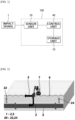
- FIG. 1 is a configuration diagram of a third-party interference monitoring system according to an embodiment of the present invention
- FIG. 2 is an explanatory diagram for describing propagation of an impact signal along the ground or a buried pipeline due to third-party interference.
- FIG. 3A is a graph showing a time domain value of an impact signal measured by a first sensor
- FIG. 3B is a graph showing a time domain value of an impact signal measured by a second sensor
- FIG. 4 is a graph showing frequency domain values when pipeline propagated vibration is included and when it is not.
- a third-party interference monitoring system 100 is a system for preventing a buried pipeline 5 from being damaged by being struck by heavy equipment or the like during unexpected third-party interference.
- the third-party interference monitoring system 100 may include a storage unit 10, a sensor unit 20, and a control unit 40.
- components of the third-party interference monitoring system 100 may be combined with each other and implemented as one, or some components may be omitted.
- reference data that is used by the control unit 40, which will be described below, to detect third-party interference may be stored in the storage unit 10.
- the reference data stored in the storage unit 10 may be, for example, a frequency band of interest and a reference magnitude range of an impact signal generated by the third-party interference.
- the reference data may be a value acquired by parameterizing morphological characteristics of a waveform in a time domain as similar waveforms in a time domain are repeated a predetermined number of times at equal intervals for the same location, as shown in FIG. 10 .
- examples of the reference data are not limited to the above-described examples, and that various pieces of data for detecting third-party interference may be stored.
- reference data of different values may be stored for each of third-party interference (hereinafter, referred to as a “dangerous third-party interference”) that is carried out in a location adjacent to the buried pipeline and is likely to damage the buried pipeline, and third-party interference (hereinafter, referred to as a “safe third-party interference”) that is carried out in a location separated a predetermined distance from the buried pipeline and is unlikely to damage the buried pipeline.
- a diangerous third-party interference that is carried out in a location adjacent to the buried pipeline and is likely to damage the buried pipeline
- safety third-party interference third-party interference
- the reference data may be acquired by performing an experiment in advance on the buried pipeline 5, which is a subject of actual observation, or a pipeline having the same material and specification as the buried pipeline 5.
- the experiment may be performed in the ground 6 where the buried pipeline 5 is actually buried, or in an environment simulating it. Accordingly, the accuracy of detection of the third-party interference by the control unit 40 can be improved by reflecting the impact of ground environment in the reference data as much as possible.
- various types of logic, algorithms, and programs that are required in a process in which the control unit 40, which will be described below, acquires a time domain value of an impact signal detected by the sensor unit 20, converts the time domain value into a frequency domain value, and then determines whether third-party interference is detected based on frequency response characteristics of the corresponding impact signal may be stored.
- the storage unit 10 may include at least one type of storage medium of a memory of a flash memory type, a hard disk type, a micro type, a card type (e.g., secure digital (SD) card type, an eXtreme digital (xD) card) type, or the like, a random access memory (RAM), a static RAM (SRAM), a read-only memory (ROM), a programmable ROM (PROM), an electrically erasable PROM (EEPROM), a magnetic RAM (MRAM), and a memory of a magnetic disk type or an optical disk type.
- SD secure digital
- xD eXtreme digital
- RAM random access memory
- SRAM static RAM
- ROM read-only memory
- PROM programmable ROM
- EEPROM electrically erasable PROM
- MRAM magnetic RAM
- MRAM magnetic RAM
- the sensor unit 20 may be implemented as a vibration accelerometer, a hydrophone, a microphone, or the like, and may be installed at one location of the buried pipeline 5 to detect an impact signal related to third-party interference around the buried pipeline.
- an impact signal 1 detected by the sensor unit 20 may be an elastic wave that is propagated when heavy equipment 7 such as an excavator (backhoe) or the like strikes the ground during the third-party interference, and specifically, may be a ground propagated vibration 3 or a pipeline propagated vibration 2.
- the ground propagated vibration 3 may be an elastic wave that is propagated toward the sensor unit 20 along the ground 6 without passing through the buried pipeline 5 and the pipeline propagated vibration 2 may be an elastic wave that is propagated along the buried pipeline 5 passing through the ground 6.
- the inventors of the present invention found that when third-party interference is in progress in an area adjacent to the buried pipeline 5, not only the ground propagated vibration 3 but also the pipeline propagated vibration 2 is detected by the sensor unit 20 of the buried pipeline 5 as shown in FIGS. 2 and 3 . That is, it was found that when there is the third-party interference in the area adjacent to the buried pipeline 5, impact energy generated due to the third-party interference is transmitted to the buried pipeline 5 through the ground and is detected by the sensor unit 20.
- the inventors of the present invention was able to confirm that, as shown in the drawing, the pipeline propagated vibration 2 reaches the sensor unit 20 faster than the ground propagated vibration 3 due to a difference in media, and that, when the frequency response characteristics are analyzed as shown in FIG. 4 , the pipeline propagated vibration 2 occurs at a higher frequency than the ground propagated vibration 3. Accordingly, the inventors of the present invention found that, when a change in frequency response characteristics caused by the pipeline propagated vibration 2 is carefully observed, the presence of the third-party interference can be confirmed before the buried pipeline 5 is damaged.
- the sensor unit 20 may include a plurality of sensors, including a first sensor 22 and a second sensor 24, which are disposed to be spaced a predetermined interval from each other along an longitudinal direction of the buried pipeline 5, as shown in the drawing.
- the first sensor 22 and the second sensor 24 may independently collect impact signals generated from the same strike.
- the reason why the sensor unit 20 includes the plurality of sensors is to estimate a location of the third-party interference and improve the accuracy of detection of the third-party interference, and this will be described below.
- the sensor unit 20 may transmit data related to the detected impact signal to the control unit 40.
- the sensor unit 20 may be connected to the control unit 40 in a wired manner or may include a wireless Internet module, a short-range communication module, or the like to transmit a wireless signal to the control unit 40.
- FIG. 5 is an explanatory diagram for comparing a dangerous third-party interference that is likely to damage a buried pipeline with a safe third-party interference that is not
- FIG. 6A is a graph showing a time domain value of an impact signal during the dangerous third-party interference of FIG. 5
- FIG. 6B is a graph showing a time domain value of an impact signal during the safe third-party interference of FIG. 5
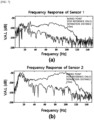
- FIG. 7A shows a frequency domain value of an impact signal measured by a first sensor and is a graph for comparing a dangerous third-party interference with a safe third-party interference
- FIG. 7A shows a frequency domain value of an impact signal measured by a first sensor and is a graph for comparing a dangerous third-party interference with a safe third-party interference
- FIG. 7A shows a frequency domain value of an impact signal measured by a first sensor and is a graph for comparing a dangerous third-party interference with a safe third-party interference
- FIG. 7B shows a frequency domain value of an impact signal measured by a second sensor and is a graph for comparing a dangerous third-party interference with a safe third-party interference.
- FIGS. 8 and 9 are explanatory diagrams for describing a process in which a control unit of a third-party interference monitoring system according to an embodiment of the present invention divides impact signals
- FIG. 10A is a graph showing time domain values of impact signals measured by a first sensor and a second sensor during a downward excavating third-party interference
- FIG. 10B is a graph showing a location of third-party interference that is estimated by analyzing the impact signals, over time.
- control unit 40 may detect the third-party interference in progress in the area adjacent to the buried pipeline by processing and analyzing information related to the above-described impact signal transmitted from the sensor unit 20.
- the control unit 40 may be implemented in the form of hardware or software or may be implemented in the form of a combination of hardware and software.
- the control unit 40 may be implemented with a microprocessor, but the present invention is not limited thereto.
- the control unit 40 may first receive data from the sensor unit 20 and acquire a time domain value of the impact signal.
- the control unit 40 may receive data from each of the first sensor 22 and the second sensor 24, as shown in FIG. 3 , and acquire a first time domain value and a second time domain value.
- control unit 40 may perform, for example, a fast Fourier transform (FFT) to convert each of the first time domain value and the second time domain value into a frequency domain value, as shown in FIG. 4 .
- FFT fast Fourier transform
- control unit 40 may detect the third-party interference on the basis of frequency response characteristics of the impact signal.
- control unit 40 may analyze the frequency response characteristics in consideration of the reference data prestored in the storage unit 10, as described above.
- control unit 40 may analyze the frequency response characteristics only for a band corresponding to a frequency band of interest among the frequency domain values.
- control unit 40 may detect the third-party interference by comparing a magnitude range of the frequency band of interest with a magnitude range stored in the storage unit 10.
- control unit 40 may check a maximum value of the frequency domain value within the frequency band of interest, and then, when the maximum value is greater than or equal to a threshold value set in the reference data, the control unit 40 may determine that the third-party interference is in progress adjacent to the buried pipeline 5. Further, as another example, the control unit 40 may check a difference between a minimum value and a maximum value of the frequency domain value within the frequency band of interest, and when the difference is greater than or equal to a threshold value set in the reference data, the control unit 40 may determine that the third-party interference is in progress.
- control unit 40 analyzes the frequency response characteristics using the reference data stored in the storage unit 10, and in addition, the control unit 40 may detect the third-party interference without reference data on the basis of an algorithm stored in the storage unit 10, such as an artificial neural network trained in advance to detect third-party interference.
- the artificial neural network may train in advance the frequency response characteristics of the impact signal acquired when the third-party interference is included, and then determine whether the impact signal includes a signal related to the third-party interference on the basis of the frequency response characteristics.
- control unit 40 may additionally determine whether the third-party interference detected as described above is the third-party interference that is likely to damage the buried pipeline 5.
- the third-party interference in progress at a portion located directly on the buried pipeline 5 or at a location adjacent to the portion located directly on the buried pipeline 5 may strike and damage the buried pipeline 5.
- FIG. 5B there is no concern that the third-party interference in progress at a location spaced a predetermined distance from a portion located directly on the buried pipeline 5 in a direction intersecting an longitudinal direction of the buried pipeline 5 affects the buried pipeline even when excavation work continues.
- the third-party interference that is likely to strike the buried pipeline is defined as a "dangerous third-party interference”
- the third-party interference that is unlikely to strike the buried pipeline is defined as a "safe third-party interference.”
- control unit 40 may determine whether the detected third-party interference is the dangerous third-party interference or the safe third-party interference. In this case, the control unit 40 may similarly classify the dangerous third-party interference and the safe third-party interference on the basis of the frequency response characteristics of the impact signal.
- the pipeline propagated vibration 2 is observed before the ground propagated vibration 3 arrives, as shown in FIG. 6A .
- the pipeline propagated vibration 2 propagated along the buried pipeline 5 may be minimal or not observed (see FIG. 6B ).
- the frequency response characteristics of the dangerous third-party interference and the safe third-party interference may be different, and the control unit 40 may distinguish the dangerous third-party interference and the safe third-party interference on the basis of the different frequency response characteristics.
- control unit 40 may retrieve reference data related to the dangerous third-party interference and the safe third-party interference from the storage unit 10 and analyze the frequency response characteristics of the impact signal, similar to when detecting the third-party interference.
- the determination of the third-party interference located at a certain distance from the buried pipeline 5 as the safe third-party interference may be differently defined depending on the user's requirements.
- the control unit 40 may use a reference data value corresponding to the user's requirements from among various pieces of reference data stored in the storage unit 10.
- the control unit 40 may retrieve the reference data corresponding to a 10 m radius from the storage unit and use the reference data to analyze the frequency response characteristics.
- the reference data of various sizes stored according to the user's requirements may be acquired through an experiment performed in advance on the corresponding buried pipeline.
- the third-party interference monitoring system 100 may select and notify only the dangerous third-party interference, thereby providing the user with more reliable information about the third-party interference.
- the control unit 40 may analyze a first frequency response characteristic related to an impact signal detected by the first sensor 22 and a second frequency response characteristic related to an impact signal detected by the second sensor 24. Then, the control unit 40 may determine that the third-party interference is in progress on the ground only when the presence of the third-party interference is confirmed as a result of analyzing the first frequency response characteristic and the second frequency response characteristic. Accordingly, the third-party interference monitoring system 100 according to the embodiment of the present invention may detect the third-party interference more accurately by minimizing misdetection.
- control unit 40 may divide each of a first time domain value and a second time domain value into a plurality of time sections, as shown in FIGS. 8 and 9 .
- the time sections may be continuously divided into 1 second intervals as shown in the drawings.
- the interval for dividing the time section is not limited to the above-described example, and may be changed variously in consideration of a distance between the first sensor 22 and the second sensor 24 and a speed of a pipeline propagated vibration propagated along the buried pipeline.
- control unit 40 may convert each of the plurality of time sections divided as described above into a frequency domain value.
- the third-party interference monitoring system 100 may divide the impact signals into unit time intervals and extract the impact signal to compare/analyze features per unit section for all continuous signals, thereby detecting the third-party interference more efficiently and transmitting related information to the user.
- the control unit 40 may divide the plurality of time sections so that an overlapping portion is present between two adjacent time sections among the plurality of divided time sections. For example, when the unit time interval is 1 second, a time domain value of 0 seconds to 2 seconds is not divided into 0 seconds to 1 second and 1 second to 2 seconds, instead may be divided into 0 seconds to 1 second, 0.5 seconds to 1.5 seconds, and 0.1 seconds to 2 seconds so as to overlap at 0.5 second intervals. In this way, the reason why the third-party interference monitoring system 100 according to the embodiment of the present invention divides the time domain value so that an overlapping portion is present is to prevent the impact signal from being omitted when determining the third-party interference.
- the first sensor 22 and the second sensor 24 are asymmetrically located from the location of the third-party interference, times it takes for the impact signal to reach each sensor may be different.
- times it takes for the impact signal to reach each sensor may be different.
- the impact signal arrived around 0.8 seconds on the first time domain value, and it may be indicated that the impact signal arrived around 1.2 seconds on the second time domain value (when the third-party interference is closer to the first sensor 22 so that a delay of 0.4 seconds occurs between both sensors).
- the control unit 40 when the control unit 40 divides the time domain value continuously, such as 0 seconds to 1 second and 1 second to 2 seconds, without an overlapping portion, for the time section of 0 seconds to 1 second, it may be determined that the impact signal is detected only on the first sensor 22, and for the time section of 1 second to 2 seconds, it may be determined that the impact signal is detected only on the second sensor 24.
- the control unit 40 determines that the third-party interference is present on the ground only when the third-party interference is confirmed as a result of analyzing both the first frequency response characteristic and the second frequency response characteristic, a problem occurs in which the control unit 40 determines that there is no third-party interference for the entire time section.
- the control unit 40 may divide the time domain value so that an overlapping portion is present.
- control unit 40 may include a plurality of sensors including the first sensor 22 and the second sensor 24 to estimate locations of the third-party interference using the following equations.
- D 1 may denote a distance between the location of the third-party interference and the first sensor
- D 2 may denote a distance between the location of the third-party interference and the second sensor
- L may denote a total length of the buried pipeline
- C may denote a propagation speed of the impact signal propagated through the buried pipeline
- ⁇ may denote a difference in arrival time between the impact signal on the first time domain value and the impact signal on the second time domain value.
- the difference ⁇ in arrival time between the two signals may be calculated more accurately by checking a peak value of a cross-correlation function.
- the control unit 40 may determine in various ways whether the plurality of impact signals are caused by the third-party interference that is in progress with downward excavation That is, the types of third-party interference include third-party interference that performs downward excavation work, which involves excavating below the ground, and may include, for example, third-party interference that does not perform downward excavation but can transmit impact energy to the ground, such as a road roller, a road crusher, etc.
- the control unit 40 may select only a downward excavating third-party interference that is highly likely to damage the buried pipeline 5 from among various types of third-party interference.
- the control unit 40 may analyze the plurality of impact signals to check whether the estimated locations of the third-party interference are the same. When the locations of the third-party interference derived by analyzing the plurality of impact signals are all within a predetermined error range, the control unit 40 may determine that the third-party interference is a downward excavating third-party interference that is in progress of downward excavation (see FIG. 10 ).
- control unit 40 may determine whether the third-party interference is a downward excavating third-party interference on the basis of the frequency response characteristics. Specifically, when the plurality of impact signals are confirmed within a predetermined period of time and at the same time, levels of a plurality of frequency response characteristics according to the plurality of impact signals are gradually increased, the control unit 40 may determine that the third-party interference is a downward excavating third-party interference.
- the third-party interference monitoring system 100 may notify the user in advance of the presence of the downward excavating third-party interference, thereby encouraging the user to more carefully monitor the progress of the third-party interference.
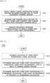
- FIGS. 11 and 12 are flowcharts of a third-party interference monitoring method according to an embodiment of the present invention.
- the sensor unit 20 installed on the buried pipeline 5 detects an impact signal propagated along the ground 6 or the buried pipeline 5 due to heavy equipment striking the ground 6 (S10).
- control unit 40 receives data from the sensor unit 20, acquires a time domain value related to the impact signal, and converts the time domain value into a frequency domain value (S20).
- control unit 40 may analyze frequency response characteristics of the impact signal to detect third-party interference (S30).
- control unit 40 may analyze the frequency response characteristics in consideration of the reference data stored in the storage unit 10 as described above.
- operation S30 of detecting the third-party interference may include, for example, an operation S31 of estimating a location of the third-party interference, an operation S32 of determining whether the third-party interference is a dangerous third-party interference, and an operation S33 of determining whether the third-party interference is a downward excavating third-party interference, as shown in FIG. 12 .
- operation S31 of estimating a location of the third-party interference may include, for example, an operation S31 of estimating a location of the third-party interference, an operation S32 of determining whether the third-party interference is a dangerous third-party interference, and an operation S33 of determining whether the third-party interference is a downward excavating third-party interference, as shown in FIG. 12 .
- specific methods of performing the operations are the same as previously described, the description thereof will not be repeated.
- FIG. 13 is a block diagram showing a computing system for operating a third-party interference monitoring system according to an embodiment of the present invention.
- a computing system 1000 may include at least one processor 1100, a memory 1300, a user interface input device 1400, a user interface output device 1500, a storage 1600, and a network interface 1700, which are connected through a system bus 1200.
- the processor 1100 may be a central processing unit (CPU) or a semiconductor device that processes instructions stored in the memory 1300 and/or storage 1600.
- the memory 1300 and the storage 1600 may include various types of volatile or non-volatile storage media.
- the memory 1300 may include an ROM and an RAM.
- the operations of the method or algorithm described in connection with the embodiments disclosed herein may be implemented directly in hardware and software modules executed by processor 1100, or a combination thereof.
- the software module may reside in a storage medium (i.e., memory 1300 and/or storage 1600) such as a RAM, a flash memory, a ROM, an EPROM, an EEPROM, a register, a hard disk, a solid state drive (SSD), a removable disk, and a compact disc read only memory (CD-ROM).
- An exemplary storage medium may be coupled to processor 1100, and the processor 1100 may read information from and write information to the storage medium. Alternatively, the storage medium may be integrated with the processor 1100.
- the processor and the storage medium may reside within an application-specific integrated circuit (ASIC).
- the ASIC may reside within a user terminal.
- the processor and the storage medium may reside as separate components within the user terminal.
- a control unit can analyze frequency response characteristics according to a pipeline propagated vibration and detect the third-party interference in advance, and thus the control unit can provide a manager of the buried pipeline with the opportunity to take preemptive action and protect the buried pipeline more effectively from the third-party interference.
- control unit in addition to detecting third-party interference, can determine whether third-party interference detected based on the above-described frequency response characteristics is a dangerous third-party interference, and thus the control unit can provide the manager of the buried pipeline with more accurate information on the third-party interference.
- control unit can analyze an impact signal in a more three-dimensional manner and determine whether the detected third-party interference is the downward excavating third-party interference that is in progress of downward excavation.
- control unit can divide an impact signal into unit time intervals so that an overlapping portion is present, and thus the control unit can minimize the impact signal omission, and accordingly, monitor the third-party interference more accurately.
Landscapes
- Physics & Mathematics (AREA)
- General Physics & Mathematics (AREA)
- Pathology (AREA)
- Biochemistry (AREA)
- Immunology (AREA)
- Health & Medical Sciences (AREA)
- Life Sciences & Earth Sciences (AREA)
- Chemical & Material Sciences (AREA)
- Analytical Chemistry (AREA)
- General Health & Medical Sciences (AREA)
- Acoustics & Sound (AREA)
- Engineering & Computer Science (AREA)
- Signal Processing (AREA)
- Probability & Statistics with Applications (AREA)
- Aviation & Aerospace Engineering (AREA)
- Mathematical Physics (AREA)
- Spectroscopy & Molecular Physics (AREA)
- Geophysics And Detection Of Objects (AREA)
Abstract
Description
- This application claims priority to and the benefit of
Korean Patent Application No. 10-2021-0145623, filed on October 28, 2021 - The present invention relates to a third-party interference monitoring system and method, and more specifically, to a monitoring system and method for detecting in advance third-party interference that is likely to damage a buried pipeline.
- Water supply pipes are social infrastructures that supply large quantities of water resources. Most of these water supply pipes are being operated while buried in the ground.
- Such buried pipelines may be unexpectedly damaged due to excavation work of heavy equipment by a third-party interference during construction in an adjacent area. Accordingly, the damaged buried pipelines are either left in a state where the contents can leak, or require somewhat cumbersome replacement work, causing social costs.
- In order to solve the above problem, technology for early detection of damage to buried pipelines has been studied. However, in the case of buried pipeline detection technology, most technologies are for detecting buried pipes that have already been damaged by external impacts etc.. When such buried pipeline detection technology is used, damage to buried pipes cannot be prevented in advance and only rapid follow-up measures can be taken. Therefore, there is a limit in that it is difficult to reduce replacement and repair costs related to damaged buried pipelines.
- Considering the above limit, there is an urgent necessity to develop detection technology that allows a user to respond before an accident occurs by detecting in advance third-party interference before buried pipes are damaged by heavy equipment.
- The present invention is directed to providing a monitoring system and method that can detect third-party interference in progress in an area adjacent to a buried pipeline before the buried pipeline is damaged by the third-party interference.
- The present invention is also directed to providing a monitoring system and method that can estimate and provide characteristics of third-party interference, such as whether detected third-party interference is in progress within a risk range of a buried pipeline, whether downward excavation is in progress, or the like.
- According to an aspect of the present invention, there is provided a third-party interference monitoring system to detect third-party interference in advance before a buried pipeline is damaged by the third-party interference, which includes a sensor unit installed on the buried pipeline so as to detect impact signals which are propagated along the ground or the buried pipeline when heavy equipment strikes the ground, and a control unit configured to receive data from the sensor unit, acquire time domain values of the impact signals, convert the time domain values into frequency domain values, and then detect the third-party interference on the basis of frequency response characteristics of the impact signals.
- In this case, the third-party interference monitoring system may further include a storage unit in which reference data for detecting the third-party interference is stored, wherein the control unit analyzes the frequency response characteristics in consideration of the reference data.
- In this case, the reference data may include a frequency band of interest and a reference magnitude range, and the control unit may compare a magnitude range of a band corresponding to the frequency band of interest among the frequency domain values with the reference magnitude range and detect the third-party interference.
- In this case, the frequency band of interest and the reference magnitude range may be acquired by performing an experiment in advance on the buried pipeline or a pipeline having the same material and specification as the buried pipeline.
- In this case, the control unit may determine whether the detected third-party interference is a dangerous third-party interference that is likely to damage the buried pipeline on the basis of the frequency response characteristics.
- In this case, the control unit may determine whether the detected third-party interference is a downward excavating in progress of downward excavation on the basis of the frequency response characteristics.
- In this case, when a plurality of impact signals are checked within a predetermined period of time and levels of frequency response characteristics of the plurality of impact signals are gradually increased, the control unit may determine that the third-party interference is a downward excavating third-party interference.
- In this case, the sensor unit may include a first sensor and a second sensor that are disposed to be spaced a predetermined interval from each other along an longitudinal direction of the buried pipeline, and the control unit may receive data from each of the first sensor and the second sensor, acquire a first time domain value and a second time domain value, and then convert the first time domain value and the second time domain value into a first frequency domain value and a second frequency domain value, respectively.
- In this case, the control unit may analyze frequency response characteristics of an impact signal detected by the first sensor and frequency response characteristics of an impact signal detected by the second sensor, and when the presence of the third-party interference is confirmed in both of the cases, the control unit may determine that the third-party interference is detected.
- In this case, the control unit may divide each of the first time domain value and the second time domain value into a plurality of time sections so that an overlapping portion is present between two adjacent time sections, and then convert each of the first time domain value and the second time domain value into a frequency domain value.
- In this case, the control unit may estimate a location of the third-party interference using the following equations:

- In this case, when a plurality of impact signals are checked and a plurality of locations of the third-party interference that are estimated by analyzing each of the plurality of impact signals are all within a predetermined error range, the control unit may determine that the third-party interference is the downward excavating third-party interference.
- In this case, the control unit may detect the third-party interference on the basis of morphological characteristics of a waveform in the time domain in addition to the frequency response characteristics.
- According to another aspect of the present invention, there is provided a third-party interference monitoring method to detect third-party interference in advance before a buried pipeline is damaged by the third-party interference, which includes detecting, by a sensor unit installed on the buried pipeline, an impact signal which is propagated along the ground or the buried pipeline due to heavy equipment striking the ground; receiving, by a control unit, data from the sensor unit, acquiring a time domain value related to the impact signal, and then converting the time domain value into a frequency domain value; and analyzing, by the control unit, frequency response characteristics of the impact signal and detecting the third-party interference.
- In this case, the analyzing of, by the control unit, the frequency response characteristics of the impact signal and detecting the third-party interference may include estimating a location of the third-party interference; determining whether the third-party interference is a dangerous third-party interference that is likely to damage the buried pipeline; and analyzing the location of the third-party interference and determining whether the third-party interference is a downward excavating third-party interference in progress of downward excavation.
- The above and other objects, features and advantages of the present invention will become more apparent to those of ordinary skill in the art by describing exemplary embodiments thereof in detail with reference to the accompanying drawings, in which:
-
FIG. 1 is a configuration diagram of a third-party interference monitoring system according to an embodiment of the present invention; -
FIG. 2 is an explanatory diagram for describing propagation of an impact signal along the ground or a buried pipeline due to third-party interference; -
FIG. 3A is a graph showing a time domain value of an impact signal measured by a first sensor, andFIG. 3B is a graph showing a time domain value of an impact signal measured by a second sensor; -
FIG. 4 is a graph showing frequency domain values when a pipeline propagated vibration is included and when it is not; -
FIG. 5 is an explanatory diagram for comparing a dangerous third-party interference that is likely to damage a buried pipeline with a safe third-party interference that is not; -
FIG. 6A is a graph showing a time domain value of an impact signal during the dangerous third-party interference ofFIG. 5, and FIG. 6B is a graph showing a time domain value of an impact signal during the safe third-party interference ofFIG. 5 ; -
FIG. 7A shows a frequency domain value of an impact signal measured by a first sensor and is a graph for comparing a dangerous third-party interference with a safe third-party interference, andFIG. 7B shows a frequency domain value of an impact signal measured by a second sensor and is a graph for comparing a dangerous third-party interference with a safe third-party interference; -
FIGS. 8 and9 are explanatory diagrams for describing a process in which a control unit of a third-party interference monitoring system according to an embodiment of the present invention divides impact signals; -
FIG. 10A is a graph showing time domain values of impact signals measured by a first sensor and a second sensor during a downward excavating third-party interference, andFIG. 10B is a graph showing a location of third-party interference that is estimated by analyzing the impact signals, over time; -
FIGS. 11 and 12 are flowcharts of a third-party interference monitoring method according to an embodiment of the present invention; and -
FIG. 13 is a block diagram showing a computing system for operating a third-party interference monitoring system according to an embodiment of the present invention. - Hereinafter, embodiments that are easily performed by those skilled in the art will be described in detail with reference to the accompanying drawings. Embodiments of the present invention may be implemented in several different forms, and are not limited to embodiments described herein. In the drawings, parts not related to the description may be omitted to clearly describe the present invention, and the same reference numerals may be used for the same or similar elements throughout the specification. Further, thicknesses of lines, sizes of components, and the like illustrated in the drawings may be exaggerated for clarity and convenience of description.
-
FIG. 1 is a configuration diagram of a third-party interference monitoring system according to an embodiment of the present invention, andFIG. 2 is an explanatory diagram for describing propagation of an impact signal along the ground or a buried pipeline due to third-party interference. Further,FIG. 3A is a graph showing a time domain value of an impact signal measured by a first sensor,FIG. 3B is a graph showing a time domain value of an impact signal measured by a second sensor, andFIG. 4 is a graph showing frequency domain values when pipeline propagated vibration is included and when it is not. - A third-party
interference monitoring system 100 according to the embodiment of the present invention is a system for preventing a buriedpipeline 5 from being damaged by being struck by heavy equipment or the like during unexpected third-party interference. - To this end, as shown in
FIG. 1 , the third-partyinterference monitoring system 100 according to the embodiment of the present invention may include astorage unit 10, asensor unit 20, and acontrol unit 40. In this case, depending on a method of implementing the third-partyinterference monitoring system 100 according to the embodiment of the present invention, components of the third-partyinterference monitoring system 100 may be combined with each other and implemented as one, or some components may be omitted. - Referring to the components, first, reference data that is used by the
control unit 40, which will be described below, to detect third-party interference may be stored in thestorage unit 10. - In this case, the reference data stored in the
storage unit 10 may be, for example, a frequency band of interest and a reference magnitude range of an impact signal generated by the third-party interference. As another example, the reference data may be a value acquired by parameterizing morphological characteristics of a waveform in a time domain as similar waveforms in a time domain are repeated a predetermined number of times at equal intervals for the same location, as shown inFIG. 10 . However, it should be noted that examples of the reference data are not limited to the above-described examples, and that various pieces of data for detecting third-party interference may be stored. - In this case, in the
storage unit 10, reference data of different values may be stored for each of third-party interference (hereinafter, referred to as a "dangerous third-party interference") that is carried out in a location adjacent to the buried pipeline and is likely to damage the buried pipeline, and third-party interference (hereinafter, referred to as a "safe third-party interference") that is carried out in a location separated a predetermined distance from the buried pipeline and is unlikely to damage the buried pipeline. - In this case, the reference data may be acquired by performing an experiment in advance on the buried
pipeline 5, which is a subject of actual observation, or a pipeline having the same material and specification as the buriedpipeline 5. In this case, the experiment may be performed in theground 6 where the buriedpipeline 5 is actually buried, or in an environment simulating it. Accordingly, the accuracy of detection of the third-party interference by thecontrol unit 40 can be improved by reflecting the impact of ground environment in the reference data as much as possible. - Further, in the
storage unit 10, various types of logic, algorithms, and programs that are required in a process in which thecontrol unit 40, which will be described below, acquires a time domain value of an impact signal detected by thesensor unit 20, converts the time domain value into a frequency domain value, and then determines whether third-party interference is detected based on frequency response characteristics of the corresponding impact signal may be stored. - Meanwhile, the
storage unit 10 may include at least one type of storage medium of a memory of a flash memory type, a hard disk type, a micro type, a card type (e.g., secure digital (SD) card type, an eXtreme digital (xD) card) type, or the like, a random access memory (RAM), a static RAM (SRAM), a read-only memory (ROM), a programmable ROM (PROM), an electrically erasable PROM (EEPROM), a magnetic RAM (MRAM), and a memory of a magnetic disk type or an optical disk type. - Next, for example, the
sensor unit 20 may be implemented as a vibration accelerometer, a hydrophone, a microphone, or the like, and may be installed at one location of the buriedpipeline 5 to detect an impact signal related to third-party interference around the buried pipeline. - In this case, referring to
FIG. 2 , animpact signal 1 detected by thesensor unit 20 may be an elastic wave that is propagated whenheavy equipment 7 such as an excavator (backhoe) or the like strikes the ground during the third-party interference, and specifically, may be a ground propagatedvibration 3 or a pipeline propagatedvibration 2. Here, as shown in the drawing, the ground propagatedvibration 3 may be an elastic wave that is propagated toward thesensor unit 20 along theground 6 without passing through the buriedpipeline 5 and the pipeline propagatedvibration 2 may be an elastic wave that is propagated along the buriedpipeline 5 passing through theground 6. - In this regard, the inventors of the present invention found that when third-party interference is in progress in an area adjacent to the buried
pipeline 5, not only the ground propagatedvibration 3 but also the pipeline propagatedvibration 2 is detected by thesensor unit 20 of the buriedpipeline 5 as shown inFIGS. 2 and3 . That is, it was found that when there is the third-party interference in the area adjacent to the buriedpipeline 5, impact energy generated due to the third-party interference is transmitted to the buriedpipeline 5 through the ground and is detected by thesensor unit 20. In particular, the inventors of the present invention was able to confirm that, as shown in the drawing, the pipeline propagatedvibration 2 reaches thesensor unit 20 faster than the ground propagatedvibration 3 due to a difference in media, and that, when the frequency response characteristics are analyzed as shown inFIG. 4 , the pipeline propagatedvibration 2 occurs at a higher frequency than the ground propagatedvibration 3. Accordingly, the inventors of the present invention found that, when a change in frequency response characteristics caused by the pipeline propagatedvibration 2 is carefully observed, the presence of the third-party interference can be confirmed before the buriedpipeline 5 is damaged. - In an embodiment of the present invention, the
sensor unit 20 may include a plurality of sensors, including afirst sensor 22 and asecond sensor 24, which are disposed to be spaced a predetermined interval from each other along an longitudinal direction of the buriedpipeline 5, as shown in the drawing. In this case, thefirst sensor 22 and thesecond sensor 24 may independently collect impact signals generated from the same strike. In an embodiment of the present invention, the reason why thesensor unit 20 includes the plurality of sensors is to estimate a location of the third-party interference and improve the accuracy of detection of the third-party interference, and this will be described below. - Meanwhile, the
sensor unit 20 may transmit data related to the detected impact signal to thecontrol unit 40. To this end, thesensor unit 20 may be connected to thecontrol unit 40 in a wired manner or may include a wireless Internet module, a short-range communication module, or the like to transmit a wireless signal to thecontrol unit 40. -
FIG. 5 is an explanatory diagram for comparing a dangerous third-party interference that is likely to damage a buried pipeline with a safe third-party interference that is not,FIG. 6A is a graph showing a time domain value of an impact signal during the dangerous third-party interference ofFIG. 5, and FIG. 6B is a graph showing a time domain value of an impact signal during the safe third-party interference ofFIG. 5 . Further,FIG. 7A shows a frequency domain value of an impact signal measured by a first sensor and is a graph for comparing a dangerous third-party interference with a safe third-party interference, andFIG. 7B shows a frequency domain value of an impact signal measured by a second sensor and is a graph for comparing a dangerous third-party interference with a safe third-party interference. Then,FIGS. 8 and9 are explanatory diagrams for describing a process in which a control unit of a third-party interference monitoring system according to an embodiment of the present invention divides impact signals,FIG. 10A is a graph showing time domain values of impact signals measured by a first sensor and a second sensor during a downward excavating third-party interference, andFIG. 10B is a graph showing a location of third-party interference that is estimated by analyzing the impact signals, over time. - Next, the
control unit 40 may detect the third-party interference in progress in the area adjacent to the buried pipeline by processing and analyzing information related to the above-described impact signal transmitted from thesensor unit 20. Thecontrol unit 40 may be implemented in the form of hardware or software or may be implemented in the form of a combination of hardware and software. Preferably, thecontrol unit 40 may be implemented with a microprocessor, but the present invention is not limited thereto. - In order to detect the third-party interference, the
control unit 40 may first receive data from thesensor unit 20 and acquire a time domain value of the impact signal. In this case, when thesensor unit 20 includes a plurality of sensors, thecontrol unit 40 may receive data from each of thefirst sensor 22 and thesecond sensor 24, as shown inFIG. 3 , and acquire a first time domain value and a second time domain value. - Thereafter, the
control unit 40 may perform, for example, a fast Fourier transform (FFT) to convert each of the first time domain value and the second time domain value into a frequency domain value, as shown inFIG. 4 . - Then, the
control unit 40 may detect the third-party interference on the basis of frequency response characteristics of the impact signal. In this case, thecontrol unit 40 may analyze the frequency response characteristics in consideration of the reference data prestored in thestorage unit 10, as described above. - As an illustrative example related to the above, the
control unit 40 may analyze the frequency response characteristics only for a band corresponding to a frequency band of interest among the frequency domain values. - More specifically, when comparing a case in which third-party interference is in progress adjacent to a buried pipeline such that an impact signal includes both a pipeline propagated
vibration 2 and a ground propagated vibration 3 (seeFIG. 5A ) with a case in which third-party interference is in progress at a location far away from a buried pipeline or there is no third-party interference such that an impact signal mainly includes a ground propagated vibration 3 (seeFIG. 5B ), it can be seen that frequency responses in a frequency band of approximately 20 Hz or less or 120 Hz or more show almost similar characteristics, as shown inFIG. 7 . However, in the case of a 20 Hz to 120 Hz band (frequency band of interest), it can be seen that a level difference between two frequency responses is significantly large. Therefore, thecontrol unit 40 may detect the third-party interference more accurately and rapidly by analyzing the frequency response characteristics of only a specific frequency band of interest. - Further, the
control unit 40 may detect the third-party interference by comparing a magnitude range of the frequency band of interest with a magnitude range stored in thestorage unit 10. - For example, the
control unit 40 may check a maximum value of the frequency domain value within the frequency band of interest, and then, when the maximum value is greater than or equal to a threshold value set in the reference data, thecontrol unit 40 may determine that the third-party interference is in progress adjacent to the buriedpipeline 5. Further, as another example, thecontrol unit 40 may check a difference between a minimum value and a maximum value of the frequency domain value within the frequency band of interest, and when the difference is greater than or equal to a threshold value set in the reference data, thecontrol unit 40 may determine that the third-party interference is in progress. - However, it is only an example that the
control unit 40 analyzes the frequency response characteristics using the reference data stored in thestorage unit 10, and in addition, thecontrol unit 40 may detect the third-party interference without reference data on the basis of an algorithm stored in thestorage unit 10, such as an artificial neural network trained in advance to detect third-party interference. In this case, the artificial neural network may train in advance the frequency response characteristics of the impact signal acquired when the third-party interference is included, and then determine whether the impact signal includes a signal related to the third-party interference on the basis of the frequency response characteristics. - Meanwhile, the
control unit 40 may additionally determine whether the third-party interference detected as described above is the third-party interference that is likely to damage the buriedpipeline 5. - Specifically, as shown in
FIG. 5A , when excavation work by heavy equipment continues, the third-party interference in progress at a portion located directly on the buriedpipeline 5 or at a location adjacent to the portion located directly on the buriedpipeline 5 may strike and damage the buriedpipeline 5. On the other hand, as shown inFIG. 5B , there is no concern that the third-party interference in progress at a location spaced a predetermined distance from a portion located directly on the buriedpipeline 5 in a direction intersecting an longitudinal direction of the buriedpipeline 5 affects the buried pipeline even when excavation work continues. Hereinafter, in this specification, the third-party interference that is likely to strike the buried pipeline is defined as a "dangerous third-party interference," and the third-party interference that is unlikely to strike the buried pipeline is defined as a "safe third-party interference." - In this regard, the
control unit 40 may determine whether the detected third-party interference is the dangerous third-party interference or the safe third-party interference. In this case, thecontrol unit 40 may similarly classify the dangerous third-party interference and the safe third-party interference on the basis of the frequency response characteristics of the impact signal. - More specifically, even when it is the same third-party interference, in the case of the dangerous third-party interference (see
FIG. 5A ), the pipeline propagatedvibration 2 is observed before the ground propagatedvibration 3 arrives, as shown inFIG. 6A . However, in the case of the safe third-party interference (seeFIG. 6B ), since a source of strike, such as heavy equipment or the like, is located at a location somewhat separated from the buriedpipeline 5, unlike in the dangerous third-party interference, the pipeline propagatedvibration 2 propagated along the buriedpipeline 5 may be minimal or not observed (seeFIG. 6B ). As a result, as shown inFIG. 7 , the frequency response characteristics of the dangerous third-party interference and the safe third-party interference may be different, and thecontrol unit 40 may distinguish the dangerous third-party interference and the safe third-party interference on the basis of the different frequency response characteristics. - In this case, the
control unit 40 may retrieve reference data related to the dangerous third-party interference and the safe third-party interference from thestorage unit 10 and analyze the frequency response characteristics of the impact signal, similar to when detecting the third-party interference. - In this case, the determination of the third-party interference located at a certain distance from the buried
pipeline 5 as the safe third-party interference may be differently defined depending on the user's requirements. To this end, thecontrol unit 40 may use a reference data value corresponding to the user's requirements from among various pieces of reference data stored in thestorage unit 10. - For example, when the user intends to detect only the third-party interference located within a 10 m radius from a portion located directly on the buried pipeline as the dangerous third-party interference, the
control unit 40 may retrieve the reference data corresponding to a 10 m radius from the storage unit and use the reference data to analyze the frequency response characteristics. Here, the reference data of various sizes stored according to the user's requirements may be acquired through an experiment performed in advance on the corresponding buried pipeline. In this way, the third-partyinterference monitoring system 100 according to the embodiment of the present invention may select and notify only the dangerous third-party interference, thereby providing the user with more reliable information about the third-party interference. - In an embodiment of the present invention, when the
sensor unit 20 includes a plurality ofsensors control unit 40 may analyze a first frequency response characteristic related to an impact signal detected by thefirst sensor 22 and a second frequency response characteristic related to an impact signal detected by thesecond sensor 24. Then, thecontrol unit 40 may determine that the third-party interference is in progress on the ground only when the presence of the third-party interference is confirmed as a result of analyzing the first frequency response characteristic and the second frequency response characteristic. Accordingly, the third-partyinterference monitoring system 100 according to the embodiment of the present invention may detect the third-party interference more accurately by minimizing misdetection. - In this regard, the
control unit 40 may divide each of a first time domain value and a second time domain value into a plurality of time sections, as shown inFIGS. 8 and9 . For example, the time sections may be continuously divided into 1 second intervals as shown in the drawings. However, the interval for dividing the time section is not limited to the above-described example, and may be changed variously in consideration of a distance between thefirst sensor 22 and thesecond sensor 24 and a speed of a pipeline propagated vibration propagated along the buried pipeline. - Then, the
control unit 40 may convert each of the plurality of time sections divided as described above into a frequency domain value. In this way, the third-partyinterference monitoring system 100 according to the embodiment of the present invention may divide the impact signals into unit time intervals and extract the impact signal to compare/analyze features per unit section for all continuous signals, thereby detecting the third-party interference more efficiently and transmitting related information to the user. - Referring to
FIG. 9 again, thecontrol unit 40 may divide the plurality of time sections so that an overlapping portion is present between two adjacent time sections among the plurality of divided time sections. For example, when the unit time interval is 1 second, a time domain value of 0 seconds to 2 seconds is not divided into 0 seconds to 1 second and 1 second to 2 seconds, instead may be divided into 0 seconds to 1 second, 0.5 seconds to 1.5 seconds, and 0.1 seconds to 2 seconds so as to overlap at 0.5 second intervals. In this way, the reason why the third-partyinterference monitoring system 100 according to the embodiment of the present invention divides the time domain value so that an overlapping portion is present is to prevent the impact signal from being omitted when determining the third-party interference. - Specifically, when the
first sensor 22 and thesecond sensor 24 are asymmetrically located from the location of the third-party interference, times it takes for the impact signal to reach each sensor may be different. As an illustrative example, referring toFIG. 9 , for the same shock signal, it may be indicated that the impact signal arrived around 0.8 seconds on the first time domain value, and it may be indicated that the impact signal arrived around 1.2 seconds on the second time domain value (when the third-party interference is closer to thefirst sensor 22 so that a delay of 0.4 seconds occurs between both sensors). - In this case, when the
control unit 40 divides the time domain value continuously, such as 0 seconds to 1 second and 1 second to 2 seconds, without an overlapping portion, for the time section of 0 seconds to 1 second, it may be determined that the impact signal is detected only on thefirst sensor 22, and for the time section of 1 second to 2 seconds, it may be determined that the impact signal is detected only on thesecond sensor 24. In this case, as in the above-described example, when thecontrol unit 40 determines that the third-party interference is present on the ground only when the third-party interference is confirmed as a result of analyzing both the first frequency response characteristic and the second frequency response characteristic, a problem occurs in which thecontrol unit 40 determines that there is no third-party interference for the entire time section. In order to solve the problem, thecontrol unit 40 may divide the time domain value so that an overlapping portion is present. - Meanwhile, the
control unit 40 may include a plurality of sensors including thefirst sensor 22 and thesecond sensor 24 to estimate locations of the third-party interference using the following equations.
- In this case, D1 may denote a distance between the location of the third-party interference and the first sensor, D2 may denote a distance between the location of the third-party interference and the second sensor, L may denote a total length of the buried pipeline, C may denote a propagation speed of the impact signal propagated through the buried pipeline, and τ may denote a difference in arrival time between the impact signal on the first time domain value and the impact signal on the second time domain value.
- Here, the difference τ in arrival time between the two signals may be calculated more accurately by checking a peak value of a cross-correlation function.
- Then, when a plurality of impact signals are confirmed to appear continuously at predetermined time intervals on a time domain value as shown in
FIG. 10 , thecontrol unit 40 may determine in various ways whether the plurality of impact signals are caused by the third-party interference that is in progress with downward excavation That is, the types of third-party interference include third-party interference that performs downward excavation work, which involves excavating below the ground, and may include, for example, third-party interference that does not perform downward excavation but can transmit impact energy to the ground, such as a road roller, a road crusher, etc. Thecontrol unit 40 may select only a downward excavating third-party interference that is highly likely to damage the buriedpipeline 5 from among various types of third-party interference. - To this end, first, the
control unit 40 may analyze the plurality of impact signals to check whether the estimated locations of the third-party interference are the same. When the locations of the third-party interference derived by analyzing the plurality of impact signals are all within a predetermined error range, thecontrol unit 40 may determine that the third-party interference is a downward excavating third-party interference that is in progress of downward excavation (seeFIG. 10 ). - In addition, the
control unit 40 may determine whether the third-party interference is a downward excavating third-party interference on the basis of the frequency response characteristics. Specifically, when the plurality of impact signals are confirmed within a predetermined period of time and at the same time, levels of a plurality of frequency response characteristics according to the plurality of impact signals are gradually increased, thecontrol unit 40 may determine that the third-party interference is a downward excavating third-party interference. - In the case of the downward excavating third-party interference, the possibility of striking the buried
pipeline 5 may be higher compared to lateral excavation. Therefore, as described above, the third-partyinterference monitoring system 100 according to the embodiment of the present invention may notify the user in advance of the presence of the downward excavating third-party interference, thereby encouraging the user to more carefully monitor the progress of the third-party interference. -
FIGS. 11 and 12 are flowcharts of a third-party interference monitoring method according to an embodiment of the present invention. - First, the
sensor unit 20 installed on the buriedpipeline 5 detects an impact signal propagated along theground 6 or the buriedpipeline 5 due to heavy equipment striking the ground 6 (S10). - Thereafter, the
control unit 40 receives data from thesensor unit 20, acquires a time domain value related to the impact signal, and converts the time domain value into a frequency domain value (S20). - Next, the
control unit 40 may analyze frequency response characteristics of the impact signal to detect third-party interference (S30). In this case, thecontrol unit 40 may analyze the frequency response characteristics in consideration of the reference data stored in thestorage unit 10 as described above. - In this case, operation S30 of detecting the third-party interference may include, for example, an operation S31 of estimating a location of the third-party interference, an operation S32 of determining whether the third-party interference is a dangerous third-party interference, and an operation S33 of determining whether the third-party interference is a downward excavating third-party interference, as shown in
FIG. 12 . In this case, since specific methods of performing the operations are the same as previously described, the description thereof will not be repeated. -
FIG. 13 is a block diagram showing a computing system for operating a third-party interference monitoring system according to an embodiment of the present invention. - Referring to
FIG. 13 , the third-party interference monitoring method according to the embodiment of the present invention described above may be implemented through a computing system. Acomputing system 1000 may include at least oneprocessor 1100, amemory 1300, a userinterface input device 1400, a userinterface output device 1500, astorage 1600, and anetwork interface 1700, which are connected through a system bus 1200. - The
processor 1100 may be a central processing unit (CPU) or a semiconductor device that processes instructions stored in thememory 1300 and/orstorage 1600. Thememory 1300 and thestorage 1600 may include various types of volatile or non-volatile storage media. For example, thememory 1300 may include an ROM and an RAM. - Therefore, the operations of the method or algorithm described in connection with the embodiments disclosed herein may be implemented directly in hardware and software modules executed by
processor 1100, or a combination thereof. The software module may reside in a storage medium (i.e.,memory 1300 and/or storage 1600) such as a RAM, a flash memory, a ROM, an EPROM, an EEPROM, a register, a hard disk, a solid state drive (SSD), a removable disk, and a compact disc read only memory (CD-ROM). An exemplary storage medium may be coupled toprocessor 1100, and theprocessor 1100 may read information from and write information to the storage medium. Alternatively, the storage medium may be integrated with theprocessor 1100. The processor and the storage medium may reside within an application-specific integrated circuit (ASIC). The ASIC may reside within a user terminal. Alternatively, the processor and the storage medium may reside as separate components within the user terminal. - According to the present invention, before a buried pipeline is damaged by an unexpected third-party interference, a control unit can analyze frequency response characteristics according to a pipeline propagated vibration and detect the third-party interference in advance, and thus the control unit can provide a manager of the buried pipeline with the opportunity to take preemptive action and protect the buried pipeline more effectively from the third-party interference.
- Further, in the present invention, in addition to detecting third-party interference, the control unit can determine whether third-party interference detected based on the above-described frequency response characteristics is a dangerous third-party interference, and thus the control unit can provide the manager of the buried pipeline with more accurate information on the third-party interference.
- Further, in the present invention, the control unit can analyze an impact signal in a more three-dimensional manner and determine whether the detected third-party interference is the downward excavating third-party interference that is in progress of downward excavation.
- Further, in the present invention, the above-described control unit can divide an impact signal into unit time intervals so that an overlapping portion is present, and thus the control unit can minimize the impact signal omission, and accordingly, monitor the third-party interference more accurately.
- While the present invention has been described with reference to exemplary embodiments thereof, the spirit of the present invention is not limited to the embodiments presented in this specification. Those skilled in the art who understand the spirit of the present invention may easily suggest other embodiments by adding, changing, or deleting elements within the scope of the same concept, and the other embodiments are also within the spirit of the present invention.
Claims (15)
- A third-party interference monitoring system to detect third-party interference in advance before a buried pipeline buried in the ground is damaged by the third-party interference, comprising:a sensor unit installed on the buried pipeline so as to detect impact signals which are propagated along the ground or the buried pipeline when heavy equipment strikes the ground; anda control unit configured to receive data from the sensor unit, acquire time domain values of the impact signals, convert the time domain values into frequency domain values, and then detect the third-party interference on the basis of frequency response characteristics of the impact signals.
- The third-party interference monitoring system of claim 1, further comprising a storage unit in which reference data for detecting the third-party interference is stored,
wherein the control unit analyzes the frequency response characteristics in consideration of the reference data. - The third-party interference monitoring system of claim 2, wherein the reference data includes a frequency band of interest and a reference magnitude range, and
the control unit compares a magnitude range of a band corresponding to the frequency band of interest among the frequency domain values with the reference magnitude range and detects the third-party interference. - The third-party interference monitoring system of claim 2, wherein the frequency band of interest and the reference magnitude range are acquired by performing an experiment in advance on the buried pipeline or a pipeline having the same material and specification as the buried pipeline.
- The third-party interference monitoring system of claim 1, wherein the control unit determines whether the detected third-party interference is a dangerous third-party interference that is likely to damage the buried pipeline on the basis of the frequency response characteristics.
- The third-party interference monitoring system of claim 1, wherein the control unit determines whether the detected third-party interference is a downward excavating third-party interference in progress of downward excavation on the basis of the frequency response characteristics.
- The third-party interference monitoring system of claim 6, wherein, when a plurality of impact signals are checked within a predetermined period of time and levels of frequency response characteristics of the plurality of impact signals are gradually increased, the control unit determines that the third-party interference is a downward excavating third-party interference.
- The third-party interference monitoring system of claim 1, wherein the sensor unit includes a first sensor and a second sensor that are disposed to be spaced a predetermined interval from each other along an longitudinal direction of the buried pipeline, and
the control unit receives data from each of the first sensor and the second sensor, acquires a first time domain value and a second time domain value, and then converts the first time domain value and the second time domain value into a first frequency domain value and a second frequency domain value, respectively. - The third-party interference monitoring system of claim 8, wherein the control unit analyzes frequency response characteristics of an impact signal detected by the first sensor and frequency response characteristics of an impact signal detected by the second sensor, and when the presence of the third-party interference is confirmed in both of the cases, the control unit determines that the third-party interference is detected.
- The third-party interference monitoring system of claim 9, wherein the control unit divides each of the first time domain value and the second time domain value into a plurality of time sections so that an overlapping portion is present between two adjacent time sections among the plurality of time sections, and then converts each of the first time domain value and the second time domain value into a frequency domain value.
- The third-party interference monitoring system of claim 8, wherein the control unit estimates a location of the third-party interference using the following equations:

- The third-party interference monitoring system of claim 11, wherein, when a plurality of impact signals are checked and a plurality of locations of the third-party interference that are estimated by analyzing each of the plurality of impact signals are all within a predetermined error range, the control unit determines that the third-party interference is the downward excavating third-party interference.
- The third-party interference monitoring system of claim 1, wherein the control unit detects the third-party interference on the basis of morphological characteristics of a waveform in the time domain in addition to the frequency response characteristics.
- A third-party interference monitoring method to detect third-party interference in advance before a buried pipeline buried in the ground is damaged by the third-party interference, comprising:detecting, by a sensor unit installed on the buried pipeline, an impact signal which is propagated along the ground or the buried pipeline due to heavy equipment striking the ground;receiving, by a control unit, data from the sensor unit, acquiring a time domain value related to the impact signal, and converting the time domain value into a frequency domain value; andanalyzing, by the control unit, frequency response characteristics of the impact signal and detecting the third-party interference.
- The third-party interference monitoring method of claim 14, wherein the analyzing of, by the control unit, the frequency response characteristics of the impact signal and detecting the third-party interference includes:estimating a location of the third-party interference;determining whether the third-party interference is a dangerous third-party interference that is likely to damage the buried pipeline; anddetermining whether the third-party interference is a downward excavating third-party interference in progress of downward excavation.
Applications Claiming Priority (2)
| Application Number | Priority Date | Filing Date | Title |
|---|---|---|---|
| KR1020210145623A KR102647597B1 (en) | 2021-10-28 | 2021-10-28 | Systems and methods for monitoring third-party interference |
| PCT/KR2022/016713 WO2023075509A1 (en) | 2021-10-28 | 2022-10-28 | Third-party interference monitoring system and method |
Publications (2)
| Publication Number | Publication Date |
|---|---|
| EP4425169A1 true EP4425169A1 (en) | 2024-09-04 |
| EP4425169A4 EP4425169A4 (en) | 2025-10-29 |
Family
ID=86160122
Family Applications (1)
| Application Number | Title | Priority Date | Filing Date |
|---|---|---|---|
| EP22887704.9A Pending EP4425169A4 (en) | 2021-10-28 | 2022-10-28 | SYSTEM AND METHOD FOR MONITORING THIRD-PARTY INTERFERENCE |
Country Status (4)
| Country | Link |
|---|---|
| US (1) | US20250027908A1 (en) |
| EP (1) | EP4425169A4 (en) |
| KR (1) | KR102647597B1 (en) |
| WO (1) | WO2023075509A1 (en) |
Family Cites Families (11)
| Publication number | Priority date | Publication date | Assignee | Title |
|---|---|---|---|---|
| US3860481A (en) * | 1973-01-29 | 1975-01-14 | Westinghouse Electric Corp | Metal impact monitor |
| US4519245A (en) * | 1983-04-05 | 1985-05-28 | Evans Herbert M | Method and apparatus for the non-destructive testing of materials |
| JP2000121740A (en) * | 1998-10-19 | 2000-04-28 | Nippon Telegr & Teleph Corp <Ntt> | Underground pipe monitoring system |
| US6386037B1 (en) * | 2001-06-06 | 2002-05-14 | The United States Of America As Represented By The Secretary Of The Interior | Void detector for buried pipelines and conduits using acoustic resonance |
| JP2003004519A (en) * | 2001-06-20 | 2003-01-08 | Tokyo Gas Co Ltd | Monitoring system for preventing damage to buried pipes |
| KR20060012556A (en) * | 2005-12-26 | 2006-02-08 | 한국가스공사연구개발원 | Third-Party Monitoring Method by Frequency Spectral Density Analysis |
| KR20110037658A (en) * | 2009-10-07 | 2011-04-13 | 한국가스공사연구개발원 | Shock sensing device and method of piping |
| KR101106888B1 (en) * | 2009-10-09 | 2012-01-25 | 인하대학교 산학협력단 | Impact location detection method of piping |
| CN110765680A (en) * | 2019-10-10 | 2020-02-07 | 中冶京诚工程技术有限公司 | Engineering structure intelligent damage identification method, device and electronic equipment |
| KR102370765B1 (en) | 2020-05-25 | 2022-03-04 | 주식회사 화이트큐브 | Method for providing goal achievement reward |
| KR102238436B1 (en) * | 2020-09-21 | 2021-04-09 | 한국표준과학연구원 | System, apparatus and method for monitoring abnormal state of pipe |
-
2021
- 2021-10-28 KR KR1020210145623A patent/KR102647597B1/en active Active
-
2022
- 2022-10-28 WO PCT/KR2022/016713 patent/WO2023075509A1/en not_active Ceased
- 2022-10-28 US US18/704,855 patent/US20250027908A1/en active Pending
- 2022-10-28 EP EP22887704.9A patent/EP4425169A4/en active Pending
Also Published As
| Publication number | Publication date |
|---|---|
| US20250027908A1 (en) | 2025-01-23 |
| KR102647597B1 (en) | 2024-03-14 |
| EP4425169A4 (en) | 2025-10-29 |
| KR20230060909A (en) | 2023-05-08 |
| WO2023075509A1 (en) | 2023-05-04 |
Similar Documents
| Publication | Publication Date | Title |
|---|---|---|
| US9631972B2 (en) | Distributed fibre optic sensing | |
| KR101547508B1 (en) | Apparatus for predicting front geological features and the method thereof | |
| CA2734818C (en) | Tracking objects in conduits | |
| US10175350B1 (en) | Systems and methods for detecting buried objects | |
| EP2345910A1 (en) | Target detection device, target detection control program, and target detection method | |
| US20080255804A1 (en) | Generating damage probability-of-detection curves in structural health monitoring transducer networks | |
| US10458878B2 (en) | Position determination device, leak detection system, position determination method, and computer-readable recording medium | |
| WO2015146082A1 (en) | Leak-detecting device, leak detection method, and program-containing recording medium | |
| US12523523B2 (en) | Underwater noise monitoring device, underwater noise monitoring method, and storage medium | |
| CN115754597A (en) | Underground cable fault early warning method and system based on branch type optical fiber communication network monitoring | |
| Long et al. | Prediction of guided wave scattering by defects in rails using numerical modelling | |
| CN111780855A (en) | Method and system for preventing external breakage of cables based on optical fiber radial vibration source ranging and vibration identification | |
| KR101872695B1 (en) | Device and method for predicting location of structural damage | |
| US11609148B2 (en) | Method and apparatus for analysis and detection of encroachment and impact upon underground structures | |
| KR102036305B1 (en) | Backfill grouting condition evaluation method of shield tbm tunnel segment and backfill grouting condition evaluation device | |
| US20250027908A1 (en) | Third-party interference monitoring system and method | |
| CN113376024B (en) | A PCCP pipe burst monitoring and early warning system and method | |
| KR102302883B1 (en) | Apparatus and method for detecting obstruction in a near field for vehicle using ultrasonics wave | |
| US6679120B1 (en) | System and method for guided boring obstacle detection | |
| US6386037B1 (en) | Void detector for buried pipelines and conduits using acoustic resonance | |
| KR102841386B1 (en) | A Method And Apparatus For Acoustic emission/Vibration Burst Signal Detection | |
| JPH0829247A (en) | Buried object detection method and device | |
| JP6719985B2 (en) | Construction condition monitoring method, construction condition monitoring device, and automatic construction device | |
| EP3591364A1 (en) | Measurement time specification device, sensing device, measurement time specification method, and computer-readable recording medium | |
| JPH11183448A (en) | Slope failure monitoring method and system |
Legal Events
| Date | Code | Title | Description |
|---|---|---|---|
| STAA | Information on the status of an ep patent application or granted ep patent |
Free format text: STATUS: THE INTERNATIONAL PUBLICATION HAS BEEN MADE |
|
| PUAI | Public reference made under article 153(3) epc to a published international application that has entered the european phase |
Free format text: ORIGINAL CODE: 0009012 |
|
| STAA | Information on the status of an ep patent application or granted ep patent |
Free format text: STATUS: REQUEST FOR EXAMINATION WAS MADE |
|
| 17P | Request for examination filed |
Effective date: 20240425 |
|
| AK | Designated contracting states |
Kind code of ref document: A1 Designated state(s): AL AT BE BG CH CY CZ DE DK EE ES FI FR GB GR HR HU IE IS IT LI LT LU LV MC ME MK MT NL NO PL PT RO RS SE SI SK SM TR |
|
| DAV | Request for validation of the european patent (deleted) | ||
| DAX | Request for extension of the european patent (deleted) | ||
| A4 | Supplementary search report drawn up and despatched |
Effective date: 20250930 |
|
| RIC1 | Information provided on ipc code assigned before grant |
Ipc: G01N 29/04 20060101AFI20250924BHEP Ipc: G01N 29/07 20060101ALI20250924BHEP Ipc: G01N 29/12 20060101ALI20250924BHEP Ipc: G01N 29/48 20060101ALI20250924BHEP Ipc: G01N 29/44 20060101ALI20250924BHEP Ipc: F17D 5/06 20060101ALI20250924BHEP Ipc: G01M 5/00 20060101ALI20250924BHEP Ipc: G01M 7/02 20060101ALI20250924BHEP |