EP4425152A1 - Prozessor zur lebensdauerbasierten entmischung in der fluoreszenzmikroskopie - Google Patents
Prozessor zur lebensdauerbasierten entmischung in der fluoreszenzmikroskopie Download PDFInfo
- Publication number
- EP4425152A1 EP4425152A1 EP23159128.0A EP23159128A EP4425152A1 EP 4425152 A1 EP4425152 A1 EP 4425152A1 EP 23159128 A EP23159128 A EP 23159128A EP 4425152 A1 EP4425152 A1 EP 4425152A1
- Authority
- EP
- European Patent Office
- Prior art keywords
- image
- lifetime
- processor
- phasor
- subset
- Prior art date
- Legal status (The legal status is an assumption and is not a legal conclusion. Google has not performed a legal analysis and makes no representation as to the accuracy of the status listed.)
- Pending
Links
Images


Classifications
-
- G—PHYSICS
- G06—COMPUTING OR CALCULATING; COUNTING
- G06T—IMAGE DATA PROCESSING OR GENERATION, IN GENERAL
- G06T1/00—General purpose image data processing
- G06T1/20—Processor architectures; Processor configuration, e.g. pipelining
-
- G—PHYSICS
- G01—MEASURING; TESTING
- G01N—INVESTIGATING OR ANALYSING MATERIALS BY DETERMINING THEIR CHEMICAL OR PHYSICAL PROPERTIES
- G01N21/00—Investigating or analysing materials by the use of optical means, i.e. using sub-millimetre waves, infrared, visible or ultraviolet light
- G01N21/62—Systems in which the material investigated is excited whereby it emits light or causes a change in wavelength of the incident light
- G01N21/63—Systems in which the material investigated is excited whereby it emits light or causes a change in wavelength of the incident light optically excited
- G01N21/64—Fluorescence; Phosphorescence
- G01N21/6408—Fluorescence; Phosphorescence with measurement of decay time, time resolved fluorescence
-
- G—PHYSICS
- G01—MEASURING; TESTING
- G01N—INVESTIGATING OR ANALYSING MATERIALS BY DETERMINING THEIR CHEMICAL OR PHYSICAL PROPERTIES
- G01N21/00—Investigating or analysing materials by the use of optical means, i.e. using sub-millimetre waves, infrared, visible or ultraviolet light
- G01N21/62—Systems in which the material investigated is excited whereby it emits light or causes a change in wavelength of the incident light
- G01N21/63—Systems in which the material investigated is excited whereby it emits light or causes a change in wavelength of the incident light optically excited
- G01N21/64—Fluorescence; Phosphorescence
- G01N21/645—Specially adapted constructive features of fluorimeters
- G01N21/6456—Spatial resolved fluorescence measurements; Imaging
- G01N21/6458—Fluorescence microscopy
-
- G—PHYSICS
- G06—COMPUTING OR CALCULATING; COUNTING
- G06V—IMAGE OR VIDEO RECOGNITION OR UNDERSTANDING
- G06V10/00—Arrangements for image or video recognition or understanding
- G06V10/20—Image preprocessing
- G06V10/25—Determination of region of interest [ROI] or a volume of interest [VOI]
-
- G—PHYSICS
- G06—COMPUTING OR CALCULATING; COUNTING
- G06V—IMAGE OR VIDEO RECOGNITION OR UNDERSTANDING
- G06V10/00—Arrangements for image or video recognition or understanding
- G06V10/20—Image preprocessing
- G06V10/26—Segmentation of patterns in the image field; Cutting or merging of image elements to establish the pattern region, e.g. clustering-based techniques; Detection of occlusion
-
- G—PHYSICS
- G06—COMPUTING OR CALCULATING; COUNTING
- G06V—IMAGE OR VIDEO RECOGNITION OR UNDERSTANDING
- G06V10/00—Arrangements for image or video recognition or understanding
- G06V10/70—Arrangements for image or video recognition or understanding using pattern recognition or machine learning
- G06V10/764—Arrangements for image or video recognition or understanding using pattern recognition or machine learning using classification, e.g. of video objects
-
- G—PHYSICS
- G06—COMPUTING OR CALCULATING; COUNTING
- G06V—IMAGE OR VIDEO RECOGNITION OR UNDERSTANDING
- G06V20/00—Scenes; Scene-specific elements
- G06V20/60—Type of objects
- G06V20/69—Microscopic objects, e.g. biological cells or cellular parts
- G06V20/693—Acquisition
-
- G—PHYSICS
- G06—COMPUTING OR CALCULATING; COUNTING
- G06V—IMAGE OR VIDEO RECOGNITION OR UNDERSTANDING
- G06V20/00—Scenes; Scene-specific elements
- G06V20/60—Type of objects
- G06V20/69—Microscopic objects, e.g. biological cells or cellular parts
- G06V20/695—Preprocessing, e.g. image segmentation
-
- G—PHYSICS
- G06—COMPUTING OR CALCULATING; COUNTING
- G06V—IMAGE OR VIDEO RECOGNITION OR UNDERSTANDING
- G06V20/00—Scenes; Scene-specific elements
- G06V20/60—Type of objects
- G06V20/69—Microscopic objects, e.g. biological cells or cellular parts
- G06V20/698—Matching; Classification
Definitions
- the invention relates to a processor for lifetime-based unmixing in fluorescence microscopy. Further, the invention relates to a method for lifetime-based unmixing. Furthermore, the invention relates to a microscope system including a processor, a method for lifetime-based unmixing in fluorescence microscopy, and a computer program.
- Fluorescence-lifetime imaging microscopy is a specific imaging technique which can be used to identify a fluorophore in a sample by determining a decay rate of photons emitted by the fluorophore.
- an intensity of each pixel is determined by the fluorescence lifetime which can be acquired in the time domain by using e.g. a pulsed excitation light source.
- Time-correlated single-photon counting TCSPC
- Fluorescence-lifetime imaging can be used as an imaging technique e.g. in confocal microscopy and two-photon excitation microscopy.
- phasor approach is a well-established method for data visualization and image analysis as described e.g. in Vallmitjana et al., "Phasor-based image segmentation: machine learning clustering techniques", Biomedical Optics Express, Vol. 12, No. 6/1 (2021), 3410 - 3422 .
- a phasor transform that is applied to a histogram representing photon counts as a function of arrival times yields two quantities which are mapped to a two-dimensional space called phasor space.
- Spectral fluorescence-lifetime imaging allows temporal fluorescence emission decays to be simultaneously acquired in a spectrally resolved manner. For a quantitative analysis, however, spectral overlap between the different fluorophores must be considered. This can be achieved either by spectral unmixing or lifetime-based unmixing.
- lifetime-based unmixing requires extensive a priori knowledge. Such knowledge is not limited to information about the specific lifetime behavior of the fluorophores. Rather, it includes, more generally, information or expectation about the behavior of fluorophores in a sample. Furthermore, in certain samples such as model organisms, endogenous signals can also contribute significantly to complexity. Attempting to determine the fluorophore species present in a specific spectral channel based on lifetimes is therefore often compared to looking for a needle in a haystack.
- a conventional phasor approach cannot be readily used because a phasor plot shows the overall contributions of all species to an image. This results in users having to empirically look at all positions on a phasor plot to find the lifetime position that correspond to a structure they want to see. Such an approach is not easily reproducible. It is also biased by the users and cannot be automated.
- a processor for lifetime-based unmixing in fluorescence microscopy is configured to acquire an image having a plurality of pixels, each pixel providing information on both photon count and photon arrival times.
- the processor is configured to generate a phasor plot which is a vector space representation of the image.
- the processor is configured to partition the image into multiple image segments, each image segment including a subset from the plurality of pixels.
- the processor is configured to evaluate the image segments according to total photon counts of the corresponding subsets of pixels.
- the processor is further configured to execute a lifetime classification, wherein the lifetime classification comprising a step of selecting from the image segments an image segment evaluated with the largest total photon count; a step of determining a region of interest in the image encompassing the image segment; a step of determining a phasor subset in the phasor plot corresponding to the region of interest; and a step of generating a lifetime class including those image segments consistent with the phasor subset.
- the processor is configured to generate a plurality of disjunct lifetime classes by iteratively executing the lifetime classification based on the remaining image segments not assigned to one of the preceding lifetime classes and to perform lifetime-based using the disjunct lifetime classes.
- the claimed solution is based on the knowledge that individual pixels of an image usually do not contain enough information to describe a particular fluorescence lifetime. Therefore, an image acquired in a particular spectral range and carrying both fluorescence intensity and arrival time information is used as a starting point.
- the processor is configured to reduce the amount of data provided by an image that is used for identifying individual signal contributions originating from multiple fluorophores. For this purpose, the processor detects different fluorescence lifetime classes or clusters based on the fluorophore behavior present in the image-Importantly, the processor enables the lifetime classes to be detected or determined in an automated manner. It might helpful for a user to provide at least one user input to enable or initiate the automated lifetime classes detection. Such an automated detection of fluorescence lifetime classes enables fluorophore unmixing including exogenous and/or endogenous signals from a sample.
- the segmentation executed by the processor serves to create multiple image segments, each segment including a subset of pixels.
- the granularity of the segmentation is preferably selected such that the number of pixels in each segment is, on the one hand, small enough to obtain pixel-precise resolution, and, on the other, large enough to provide sufficient amount of information.
- the processor is configured to determine whether the determined phasor subset corresponding to the region of interest defines a unique position in the phasor plot. In this case, the processor is further configured to newly create the lifetime class if the determined phasor subset corresponds to the unique position and to refrain from newly creating the lifetime class if the determined phasor subset does not correspond to the unique position.
- the processor is configured to determine an average arrival time for each pixel, the average arrival time representing information on the photon arrival time.
- the average arrival time is a characteristic quantity for each fluorophore which can be calculated fast and easily.
- the average arrival time can be used to effectively determine the geometry of segmentation.
- a beneficial side effect is that the average arrival time may vary depending on the environment of the fluorophore, providing a useful parameter for analyzing the microenvironment of the fluorophore.
- the processor may be configured to calculate a minimum variance of the average arrival time for each image segment and to determine the region of interest encompassing each image segment based on the minimum variance of the average arrival time.
- the region of interest may be considered as an image portion which is centered at the respective image segment and whose spatial extent is determined by the AAT variance.
- the processor is configured to remove background from the image prior to performing lifetime-based unmixing.
- lifetime-based unmixing becomes more precise.
- the processor is configured to apply a minimum total photon count as criterion of segmentation.
- shape and size of the image segments are allowed to vary in order to ensure a sufficient photon count in each segment.
- a simpler concept is to use a regular grid pattern for segmentation so that the segments have the same size and shape.
- the processor is configured to display a spatial distribution of the disjunct lifetime classes, e.g. on a display device like a monitor to the user.
- a spatial distribution of the disjunct lifetime classes e.g. on a display device like a monitor to the user.
- channels can be provided which are unmixed in terms of fluorescence lifetime.
- a microscope which comprises a processor as described above.
- a method or lifetime-based unmixing in fluorescence microscopy comprises the following steps: acquiring an image having a plurality of pixels, each pixel providing information on both photon count and photon arrival times; generating a phasor plot which is a vector space representation of the image; partitioning the image into multiple image segments, each image segment including a subset from the plurality of pixels; evaluating the image segments according to total photon counts of the corresponding subsets of pixels; and executing a lifetime classification.
- the lifetime classification comprises a step of selecting from the image segments an image segment evaluated with the largest total photon count; a step of determining a region of interest in the image encompassing the image segment; a step of determining a phasor subset in the phasor plot corresponding to the region of interest; and a step of generating a lifetime class including those image segments consistent with the phasor subset.
- a plurality of disjunct lifetime classes is generated by iteratively executing the lifetime classification based on the remaining image segments not assigned to one of the preceding lifetime classes, and lifetime-based unmixing is performed using the disjunct life-time classes.
- Figure 1 is a block diagram showing a microscope system 100 according to an embodiment.
- the microscope system 100 may be configured as a point-scanning microscope that acquires images of a sample 102 which includes multiple fluorophores of different species emitting fluorescence light of different colors. More specifically, the microscope 100 may be adapted to perform fluorescence-lifetime imaging (FLIM) which can be applied to identify distinct fluorophores by determining decay rates of fluorescence photons emitted by the respective fluorophores.
- FLIM fluorescence-lifetime imaging
- the microscope system 100 may be equipped with suitable microscope components known in the art and generally referred to as block 104 in Figure 1 .
- the components 104 may include one or more pulsed-laser excitation sources that emit excitation light E and an optical system that directs the excitation light E onto the sample 102 and collects fluorescence light F therefrom.
- the components 104 may include one or more detectors which are configured for pixel-by-pixel imaging in multiple color channels.
- the detectors may be capable of generating lifetime-based information e.g. by time-correlated single-photon counting (TCSPC). Accordingly, it may be possible to record a fluorescence decay histogram providing information on both photon count and photon arrival times for each pixel in a specific color channel.
- the microscope system 100 may include a monitor on which a microscope image is displayed.
- the microscope system 100 further comprises a processor 106 that may be used to control an overall operation of the microscope system 100.
- the processor 106 is configured to execute a process for lifetime-based unmixing as described hereinafter.
- FIG 2 is a flow diagram showing an embodiment of a method that may be executed under the control of the processor 106 to perform lifetime-based unmixing of image signals which are acquired by means of the microscope system 100.
- the processor 106 may execute lifetime-based unmixing of image signals which are acquired by means of the microscope system 100.
- FIGs 3 to 9 an exemplary sequence of methods steps is explained with reference to Figures 3 to 9 in which these steps are illustrated.
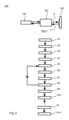
- step S1 of the exemplary method an image 310a of the sample 102 consisting of a plurality of pixels is acquired by the microscope system 100 as shown in Figure 3 .
- the image 102 may first be assessed for background by the processor 106.
- the processor 106 selects only those pixels of the image 10 for further processing which do not represent background. According to the example shown in Figure 3 , those pixels selected to be further processed are assumed to form a target image 312a.
- Each pixel of the target image 312a provides intensity information in form of a photon count.
- information on the photon arrival time such as TCSPC information is acquired.
- each pixel is associated with information on both photon count and photon arrival times.
- AAT denotes the average arrival time
- AT i denotes an arrival time of photon i
- N designates a total number of photons detected during a pixel well time of the microscope which might be a raster scanning microscope.
- a photon histogram may be obtained for each pixel based on the TCSPC information.
- step S2 a vector space representation of the image 310a is generated in form a phasor plot 310b shown in Figure 3 .
- a phasor transform is applied to a photon histogram distribution I(t) representing the photon counts as a function of the arrival times detected by means of TCSPC.
- I(t) representing the photon counts as a function of the arrival times detected by means of TCSPC.
- the phasor quantities Sand G are mapped into the phasor space as shown in Figure 3 . Accordingly, the target image 312a is transformed into a phasor region 312b representing all lifetime contributions that originate from the target image 312b.
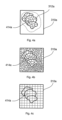
- the target image 312a is partitioned by the processor 106 into a plurality of image segments representing a spatial distribution of pixel signals.
- a granularity of the segmentation i.e. the size of each segment represented by a subset of pixels, may be determined based on the total number of photons detected by this subset of pixels during the pixel dwell time. For example, the segment size may be determined such that all pixels of a single segment have a minimum total number of photons such as e.g. at least 30 photons.
- the segmentation in step S3 may be performed by the processor 106 applying an appropriate segmentation algorithm, including machine learning (ML) or artificial intelligence (Al), while only the target image 312a is segmented and the rest of the image 310a is disregarded.
- ML machine learning
- Al artificial intelligence
- the processor 106 may also be configured to apply an appropriate fragmentation to the entire image 310a, as shown in Figure 4b , where a minimum total photon count is applied as criterion for segmentation, resulting in segments of different sizes.
- the processor 106 applies a regular grid pattern for segmentation so that all segments have the same size and shape as shown in Figure 4c .
- step S4 the processor 106 evaluates the different image segments according to the total photon counts detected in the subset of pixels that is included in each segment 414a. For this evaluation and all subsequent steps, the target image 312a is used without any thresholding. For example, the processor 106 may create a table as shown in Figure 5 (referred to herein as Table 1).
- Table 1 of Figure 5 is created by determining the total intensities I_max, I_max-1, ... , i.e. the total photons, for all segments, wherein I_max denotes the largest photon count, I_max-1 denotes the second largest the largest photon count, and so forth.
- the segments are sorted from top to bottom in order of their total the photon counts, i.e. segment 1 has the largest total photon count, segment 2 has the second largest photon count, and so forth.
- the processor 106 further calculates the phasor quantities G and S for all segments.
- G1 and S1 belongs to segment 1
- G2 and S2 belongs to segment 2, and so forth.
- the variance as calculated above may be used as a further criterion for sorting the segments in the table of Figure 5 .
- segment 1 having the largest total photon count I_max has a minimum variance denoted V_min
- segment 2 having the second largest total photon count I_max-2 has the second lowest variance denoted V_min-1, and so forth.
- this further sorting criterion determines that the one with the smaller variance will be considered first.
- step S5 the processor 106 selects a segment with the largest total photon count.
- segment 1 with photon count I_max is selected from Table 1.
- step S6 the segment selected in step S5 is considered to be a potential seeding point 614a based on which the processor 106 determines a region of interest ROI1 within the target image 312a, as illustrated in Figure 6 .
- the processor 106 creates the region of interest ROI1 starting from the seeding point 614a as a center and expanding an image portion therefrom by a value that corresponds to the AAT variance V_min indicted in the table of Figure 5 .
- ROI1 represents an image portion which is centered at the seeding point 614a, i.e. segment 1, and whose radial extent is capped based on the AAT variance V_min.
- step S7 the processor 106 calculates a phasor transform based the region of interest ROI1 shown in Figure 7 . As result, a phasor subset PP1 corresponding to the region of interest ROI1 is generated.
- step S8 the processor 106 checks whether the phasor subset PP1 defines a unique position in the phasor plot 310b, i.e. whether it represents a well-defined phasor position determined by a specific pair of phasor quantities (S; G) in Figure 7 .
- step S8 If the processor 106 determines in step S8 that the phasor subset PP1 does not represent a well-defined position in the phasor plot 310b, the processor 106 returns to step S5 and selects the segment with the next larger photon count from Table 1. For example, if segment 1 with total photon count I_max was previously selected from Table 1, segment 2 with photon count I_max-1 is now selected. Steps S6 to S8 are then repeated with the next larger total count.
- steps S5 to S8 is repeated until one of segments listed in Table 1 is found to yield a well-defined phasor position in the phasor plot 310b as shown in Figure 7 .
- step S9 the processor selects the phasor subset PP1 as a starting point for lifetime classification. This is possible since the phasor subset PP1 was identified before as a well-defined unique phasor position derived from a portion of the image 310a that is limited to ROI1.
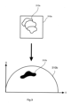
- the processor 106 determines all portions of the target image 312a that exhibit a lifetime behavior which is consistent with the phasor subset PP1. In doing so, the processor 106 may also cause these consistent image portions to be displayed on a monitor. This is illustrated in Figure 8 with the consistent image portions denoted by reference sign 814a.
- the phasor subset PP1 calculated in step S7 represents a first phasor position based on which a first lifetime class ("class 1" in Figure 5 ) is newly created.
- step S9 the processor 106 searches among the segments listed in Table 1 of Figure 5 for segments with fluorescence lifetimes that match the first lifetime class. Those segments are then classified as belonging to the first lifetime class. Whether a particular segment listed in Table 1 has a fluorescence lifetime corresponding to the first lifetime class can be quantitatively determined from the phasor quantities S and G assigned to that segment. For example, the processor 106 may determine whether the phasor quantities Sand G of a particular segment are within a predetermined tolerance range around the first phasor position which is represented by the phasor subset PP1 in the phasor plot 310b of Figure 7 .
- steps S5 to S9 the processor 106 performs a lifetime classification resulting in the afore-mentioned first lifetime class.
- the remaining segments of Table 1 that have not been assigned to the first lifetime class can now be processed by iteratively executing the lifetime classification in the same manner as described above.
- the processor 106 creates in step S10 a new (second) table similar to Table 1 of Figure 5 .
- the second table includes only the remaining segments from Table 1 that have not been classified before as belonging to the first lifetime class. Accordingly, the processor 106 now selects a segment which has the largest total photon count among the remaining segments that are listed in the second table. Then, the processor 106 ssubstantially repeats steps S5 to S9, using the second table rather than Table 1.
- the processor 106 executes a second round of lifetime classification yielding a second lifetime class disjunct from the first lifetime class.
- the processor 106 may proceed in the same manner to generate additional (third, fourth, etc.) lifetime classes.
- a third lifetime class may be created based on a third table including all remaining segments of Table 1 that have not been classified before as belonging to the preceding (first and second) lifetime classes.
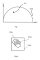
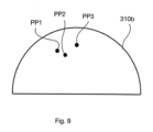
- Figure 9 illustrates the phasor plot 310b for the case where a total of three lifetime classes are considered. In this case, two further phasor subsets PP2 and PP3 are plotted in addition the first phasor subset PP1.
- This iterative classification process described above may continue until an nth lifetime class has been created based on an nth table. If no new well-defined phasor position can be found, it is assumed that all well-defined phasor positions and the corresponding lifetime classes which can be derived from the data have eventually been found. Such a final classification step is denoted Sx in the flow diagram of Figure 2 .
- the lifetime classes can be used in step Sx+1 to generate corresponding channels that are unmixed in terms of lifetime and display the spatial distribution of the lifetime classes found in the image.
- step S1 may also be omitted, in which case not only the target image 312a but the entire image 312a is processed as explained above.
- the process described above refers to a simple example in which the image data to be processed represents a single two-dimensional image.
- an image sequence such as a z-stack is recorded at time intervals, it may be appropriate to segment the image data spatially, i.e. in 3D, as well as temporally in order to process the complete data set.
- aspects have been described in the context of an apparatus, it is clear that these aspects also represent a description of the corresponding method, where a block or device corresponds to a method step or a feature of a method step. Analogously, aspects described in the context of a method step also represent a description of a corresponding block or item or feature of a corresponding apparatus.
- a microscope comprising a system as described in connection with one or more of the Figs. 1 to 9 .
- a microscope may be part of or connected to a system as described in connection with one or more of the Figs. 1 to 9 .
- Fig. 10 shows a schematic illustration of a system 1000 configured to perform a method described herein.
- the system 1000 comprises a microscope 1010 and a computer system 1020.
- the microscope 1010 is configured to take images and is connected to the computer system 1020.
- the computer system 1020 is configured to execute at least a part of a method described herein.
- the computer system 1020 may be configured to execute a machine learning algorithm.
- the computer system 1020 and microscope 1010 may be separate entities but can also be integrated together in one common housing.
- the computer system 1020 may be part of a central processing system of the microscope 1010 and/or the computer system 1020 may be part of a subcomponent of the microscope 1010, such as a sensor, an actor, a camera or an illumination unit, etc. of the microscope 1010.
- the computer system 1020 may be a local computer device (e.g. personal computer, laptop, tablet computer or mobile phone) with one or more processors and one or more storage devices or may be a distributed computer system (e.g. a cloud computing system with one or more processors and one or more storage devices distributed at various locations, for example, at a local client and/or one or more remote server farms and/or data centers).
- the computer system 1020 may comprise any circuit or combination of circuits.
- the computer system 1020 may include one or more processors which can be of any type.
- processor may mean any type of computational circuit, such as but not limited to a microprocessor, a microcontroller, a complex instruction set computing (CISC) microprocessor, a reduced instruction set computing (RISC) microprocessor, a very long instruction word (VLIW) microprocessor, a graphics processor, a digital signal processor (DSP), multiple core processor, a field programmable gate array (FPGA), for example, of a microscope or a microscope component (e.g. camera) or any other type of processor or processing circuit.
- CISC complex instruction set computing
- RISC reduced instruction set computing
- VLIW very long instruction word
- DSP digital signal processor
- FPGA field programmable gate array
- circuits that may be included in the computer system 1020 may be a custom circuit, an application-specific integrated circuit (ASIC), or the like, such as, for example, one or more circuits (such as a communication circuit) for use in wireless devices like mobile telephones, tablet computers, laptop computers, two-way radios, and similar electronic systems.
- the computer system 1020 may include one or more storage devices, which may include one or more memory elements suitable to the particular application, such as a main memory in the form of random access memory (RAM), one or more hard drives, and/or one or more drives that handle removable media such as compact disks (CD), flash memory cards, digital video disk (DVD), and the like.
- RAM random access memory
- CD compact disks
- DVD digital video disk
- the computer system 1020 may also include a display device, one or more speakers, and a keyboard and/or controller, which can include a mouse, trackball, touch screen, voice-recognition device, or any other device that permits a system user to input information into and receive information from the computer system 1020.
- a display device one or more speakers
- a keyboard and/or controller which can include a mouse, trackball, touch screen, voice-recognition device, or any other device that permits a system user to input information into and receive information from the computer system 1020.
- Some or all of the method steps may be executed by (or using) a hardware apparatus, like for example, a processor, a microprocessor, a programmable computer or an electronic circuit. In some embodiments, some one or more of the most important method steps may be executed by such an apparatus.
- embodiments of the invention can be implemented in hardware or in software.
- the implementation can be performed using a non-transitory storage medium such as a digital storage medium, for example a floppy disc, a DVD, a Blu-Ray, a CD, a ROM, a PROM, and EPROM, an EEPROM or a FLASH memory, having electronically readable control signals stored thereon, which cooperate (or are capable of cooperating) with a programmable computer system such that the respective method is performed. Therefore, the digital storage medium may be computer readable.
- Some embodiments according to the invention comprise a data carrier having electronically readable control signals, which are capable of cooperating with a programmable computer system, such that one of the methods described herein is performed.
- embodiments of the present invention can be implemented as a computer program product with a program code, the program code being operative for performing one of the methods when the computer program product runs on a computer.
- the program code may, for example, be stored on a machine readable carrier.
- inventions comprise the computer program for performing one of the methods described herein, stored on a machine readable carrier.
- an embodiment of the present invention is, therefore, a computer program having a program code for performing one of the methods described herein, when the computer program runs on a computer.
- a further embodiment of the present invention is, therefore, a storage medium (or a data carrier, or a computer-readable medium) comprising, stored thereon, the computer program for performing one of the methods described herein when it is performed by a processor.
- the data carrier, the digital storage medium or the recorded medium are typically tangible and/or non-transitionary.
- a further embodiment of the present invention is an apparatus as described herein comprising a processor and the storage medium.
- a further embodiment of the invention is, therefore, a data stream or a sequence of signals representing the computer program for performing one of the methods described herein.
- the data stream or the sequence of signals may, for example, be configured to be transferred via a data communication connection, for example, via the internet.
- a further embodiment comprises a processing means, for example, a computer or a programmable logic device, configured to, or adapted to, perform one of the methods described herein.
- a processing means for example, a computer or a programmable logic device, configured to, or adapted to, perform one of the methods described herein.
- a further embodiment comprises a computer having installed thereon the computer program for performing one of the methods described herein.
- a further embodiment according to the invention comprises an apparatus or a system configured to transfer (for example, electronically or optically) a computer program for performing one of the methods described herein to a receiver.
- the receiver may, for example, be a computer, a mobile device, a memory device or the like.
- the apparatus or system may, for example, comprise a file server for transferring the computer program to the receiver.
- a programmable logic device for example, a field programmable gate array
- a field programmable gate array may cooperate with a microprocessor in order to perform one of the methods described herein.
- the methods are preferably performed by any hardware apparatus.
Landscapes
- Engineering & Computer Science (AREA)
- Health & Medical Sciences (AREA)
- General Physics & Mathematics (AREA)
- Physics & Mathematics (AREA)
- Theoretical Computer Science (AREA)
- General Health & Medical Sciences (AREA)
- Life Sciences & Earth Sciences (AREA)
- Multimedia (AREA)
- Biomedical Technology (AREA)
- Molecular Biology (AREA)
- Immunology (AREA)
- Analytical Chemistry (AREA)
- Chemical & Material Sciences (AREA)
- Nuclear Medicine, Radiotherapy & Molecular Imaging (AREA)
- Biochemistry (AREA)
- Pathology (AREA)
- Artificial Intelligence (AREA)
- Software Systems (AREA)
- Medical Informatics (AREA)
- Evolutionary Computation (AREA)
- Databases & Information Systems (AREA)
- Computing Systems (AREA)
- Computer Vision & Pattern Recognition (AREA)
- Microscoopes, Condenser (AREA)
Priority Applications (4)
| Application Number | Priority Date | Filing Date | Title |
|---|---|---|---|
| EP23159128.0A EP4425152A1 (de) | 2023-02-28 | 2023-02-28 | Prozessor zur lebensdauerbasierten entmischung in der fluoreszenzmikroskopie |
| US18/586,622 US20240290117A1 (en) | 2023-02-28 | 2024-02-26 | Processor for lifetime-based unmixing in fluorescence microscopy |
| JP2024028227A JP2024122932A (ja) | 2023-02-28 | 2024-02-28 | 蛍光顕微鏡法におけるライフタイムベースのアンミキシングのためのプロセッサ |
| CN202410221178.2A CN118570045A (zh) | 2023-02-28 | 2024-02-28 | 荧光显微镜中基于寿命的解混的处理器 |
Applications Claiming Priority (1)
| Application Number | Priority Date | Filing Date | Title |
|---|---|---|---|
| EP23159128.0A EP4425152A1 (de) | 2023-02-28 | 2023-02-28 | Prozessor zur lebensdauerbasierten entmischung in der fluoreszenzmikroskopie |
Publications (1)
| Publication Number | Publication Date |
|---|---|
| EP4425152A1 true EP4425152A1 (de) | 2024-09-04 |
Family
ID=85410275
Family Applications (1)
| Application Number | Title | Priority Date | Filing Date |
|---|---|---|---|
| EP23159128.0A Pending EP4425152A1 (de) | 2023-02-28 | 2023-02-28 | Prozessor zur lebensdauerbasierten entmischung in der fluoreszenzmikroskopie |
Country Status (4)
| Country | Link |
|---|---|
| US (1) | US20240290117A1 (de) |
| EP (1) | EP4425152A1 (de) |
| JP (1) | JP2024122932A (de) |
| CN (1) | CN118570045A (de) |
Citations (1)
| Publication number | Priority date | Publication date | Assignee | Title |
|---|---|---|---|---|
| US20230034263A1 (en) * | 2019-11-19 | 2023-02-02 | The Regents Of The University Of California | Compositions and methods for spatial profiling of biological materials using time-resolved luminescence measurements |
Family Cites Families (3)
| Publication number | Priority date | Publication date | Assignee | Title |
|---|---|---|---|---|
| US10830701B2 (en) * | 2017-05-06 | 2020-11-10 | Howard Hughes Medical Institute | Scanned line angular projection microscopy |
| KR20240063107A (ko) * | 2021-07-21 | 2024-05-10 | 엘리먼트 바이오사이언스, 인크. | 핵산 시퀀싱을 위한 광학 시스템 및 이의 방법 |
| EP4404830B1 (de) * | 2021-09-23 | 2025-11-26 | University of Southern California | Hyperspektrales bildgebungssystem mit hybrider entmischung |
-
2023
- 2023-02-28 EP EP23159128.0A patent/EP4425152A1/de active Pending
-
2024
- 2024-02-26 US US18/586,622 patent/US20240290117A1/en active Pending
- 2024-02-28 JP JP2024028227A patent/JP2024122932A/ja active Pending
- 2024-02-28 CN CN202410221178.2A patent/CN118570045A/zh active Pending
Patent Citations (1)
| Publication number | Priority date | Publication date | Assignee | Title |
|---|---|---|---|---|
| US20230034263A1 (en) * | 2019-11-19 | 2023-02-02 | The Regents Of The University Of California | Compositions and methods for spatial profiling of biological materials using time-resolved luminescence measurements |
Non-Patent Citations (4)
| Title |
|---|
| DIGMAN M. A. ET AL.: "The Phasor Approach to Fluorescence Lifetime Imaging Analysis", BIOPHYSICAL JOURNAL: BIOPHYSICAL LETTERS, 2007, pages L14 - L16 |
| VALLMITJANA A ET AL.: "Phasor-based image segmentation: machine learning clustering techniques", BIOMEDICAL OPTICS EXPRESS, vol. 12, no. 6, 17 May 2021 (2021-05-17), pages 3410 - 3422, XP093065899 * |
| VALLMITJANA ET AL.: "Phasor-based image segmentation: machine learning clustering techniques", BIOMEDICAL OPTICS EXPRESS, vol. 12, no. 6, 2021, pages 3410 - 3422 |
| ZHANG YIDE ET AL: "Automatic segmentation of intravital fluorescence microscopy images by K-means clustering of FLIM phasors", OPTICS LETTERS, vol. 44, no. 16, 6 August 2019 (2019-08-06), US, pages 3928, XP093066083, ISSN: 0146-9592, DOI: 10.1364/OL.44.003928 * |
Also Published As
| Publication number | Publication date |
|---|---|
| JP2024122932A (ja) | 2024-09-09 |
| CN118570045A (zh) | 2024-08-30 |
| US20240290117A1 (en) | 2024-08-29 |
Similar Documents
| Publication | Publication Date | Title |
|---|---|---|
| Yang et al. | NuSeT: A deep learning tool for reliably separating and analyzing crowded cells | |
| Lidke et al. | Superresolution by localization of quantum dots using blinking statistics | |
| Ren et al. | gSLICr: SLIC superpixels at over 250Hz | |
| US20100135566A1 (en) | Analysis and classification, in particular of biological or biochemical objects, on the basis of time-lapse images, applicable in cytometric time-lapse cell analysis in image-based cytometry | |
| JP2018180635A (ja) | 画像処理装置、画像処理方法、及び画像処理プログラム | |
| US10169878B2 (en) | System and method for segmentation of three-dimensional microscope images | |
| Xiao et al. | Deep learning enhanced fast fluorescence lifetime imaging with a few photons | |
| US20250200756A1 (en) | Scalable and high precision context-guided segmentation of histological structures including ducts/glands and lumen, cluster of ducts/glands, and individual nuclei in whole slide images of tissue samples from spatial multi-parameter cellular and sub-cellular imaging platforms | |
| WO2017150194A1 (ja) | 画像処理装置、画像処理方法及びプログラム | |
| Deng et al. | Spatial covariance reconstructive (SCORE) super-resolution fluorescence microscopy | |
| CN119741301B (zh) | 一种肿瘤检测方法、系统及计算机设备 | |
| Gao et al. | Visual saliency models for text detection in real world | |
| US11373066B2 (en) | Deep model matching methods for image transformation | |
| Delpiano et al. | Automated detection of fluorescent cells in in‐resin fluorescence sections for integrated light and electron microscopy | |
| EP4425152A1 (de) | Prozessor zur lebensdauerbasierten entmischung in der fluoreszenzmikroskopie | |
| D’Antuono | Basic digital image acquisition, design, processing, analysis, management, and presentation | |
| Quicke et al. | High speed functional imaging with source localized multifocal two-photon microscopy | |
| Bearer | Overview of image analysis, image importing, and image processing using freeware | |
| US20240037755A1 (en) | Imaging device and method | |
| Cheng et al. | Discriminative segmentation of microscopic cellular images | |
| Liang et al. | A multiple hypothesis based method for particle tracking and its extension for cell segmentation | |
| Hardo et al. | Quantitative Microbiology with Microscopy: Effects of Projection and Diffraction | |
| US9589172B1 (en) | Systems and methods for interactive image analysis of digital pathology images | |
| Hajiabadi et al. | Easing the Reuse of ML Solutions by Interactive Clustering-based Autotuning in Scientific Applications | |
| US12499699B2 (en) | Systems and methods for effect size optimization of object classification |
Legal Events
| Date | Code | Title | Description |
|---|---|---|---|
| PUAI | Public reference made under article 153(3) epc to a published international application that has entered the european phase |
Free format text: ORIGINAL CODE: 0009012 |
|
| STAA | Information on the status of an ep patent application or granted ep patent |
Free format text: STATUS: THE APPLICATION HAS BEEN PUBLISHED |
|
| AK | Designated contracting states |
Kind code of ref document: A1 Designated state(s): AL AT BE BG CH CY CZ DE DK EE ES FI FR GB GR HR HU IE IS IT LI LT LU LV MC ME MK MT NL NO PL PT RO RS SE SI SK SM TR |
|
| STAA | Information on the status of an ep patent application or granted ep patent |
Free format text: STATUS: REQUEST FOR EXAMINATION WAS MADE |
|
| 17P | Request for examination filed |
Effective date: 20250303 |
|
| GRAP | Despatch of communication of intention to grant a patent |
Free format text: ORIGINAL CODE: EPIDOSNIGR1 |
|
| STAA | Information on the status of an ep patent application or granted ep patent |
Free format text: STATUS: GRANT OF PATENT IS INTENDED |
|
| INTG | Intention to grant announced |
Effective date: 20251201 |