EP4425136A1 - Rope or cable with vibration frequency meters - Google Patents
Rope or cable with vibration frequency meters Download PDFInfo
- Publication number
- EP4425136A1 EP4425136A1 EP24159586.7A EP24159586A EP4425136A1 EP 4425136 A1 EP4425136 A1 EP 4425136A1 EP 24159586 A EP24159586 A EP 24159586A EP 4425136 A1 EP4425136 A1 EP 4425136A1
- Authority
- EP
- European Patent Office
- Prior art keywords
- rope
- cable
- vibration frequency
- digitalised
- measuring
- Prior art date
- Legal status (The legal status is an assumption and is not a legal conclusion. Google has not performed a legal analysis and makes no representation as to the accuracy of the status listed.)
- Withdrawn
Links
Images


Classifications
-
- G—PHYSICS
- G01—MEASURING; TESTING
- G01L—MEASURING FORCE, STRESS, TORQUE, WORK, MECHANICAL POWER, MECHANICAL EFFICIENCY, OR FLUID PRESSURE
- G01L5/00—Apparatus for, or methods of, measuring force, work, mechanical power, or torque, specially adapted for specific purposes
- G01L5/04—Apparatus for, or methods of, measuring force, work, mechanical power, or torque, specially adapted for specific purposes for measuring tension in flexible members, e.g. ropes, cables, wires, threads, belts or bands
- G01L5/047—Specific indicating or recording arrangements, e.g. for remote indication, for indicating overload or underload
-
- A—HUMAN NECESSITIES
- A63—SPORTS; GAMES; AMUSEMENTS
- A63B—APPARATUS FOR PHYSICAL TRAINING, GYMNASTICS, SWIMMING, CLIMBING, OR FENCING; BALL GAMES; TRAINING EQUIPMENT
- A63B21/00—Exercising apparatus for developing or strengthening the muscles or joints of the body by working against a counterforce, with or without measuring devices
- A63B21/00196—Exercising apparatus for developing or strengthening the muscles or joints of the body by working against a counterforce, with or without measuring devices using pulsed counterforce, e.g. vibrating resistance means
-
- A—HUMAN NECESSITIES
- A63—SPORTS; GAMES; AMUSEMENTS
- A63B—APPARATUS FOR PHYSICAL TRAINING, GYMNASTICS, SWIMMING, CLIMBING, OR FENCING; BALL GAMES; TRAINING EQUIPMENT
- A63B21/00—Exercising apparatus for developing or strengthening the muscles or joints of the body by working against a counterforce, with or without measuring devices
- A63B21/15—Arrangements for force transmissions
- A63B21/151—Using flexible elements for reciprocating movements, e.g. ropes or chains
-
- A—HUMAN NECESSITIES
- A63—SPORTS; GAMES; AMUSEMENTS
- A63B—APPARATUS FOR PHYSICAL TRAINING, GYMNASTICS, SWIMMING, CLIMBING, OR FENCING; BALL GAMES; TRAINING EQUIPMENT
- A63B21/00—Exercising apparatus for developing or strengthening the muscles or joints of the body by working against a counterforce, with or without measuring devices
- A63B21/28—Devices for two persons operating in opposition or in cooperation
-
- D—TEXTILES; PAPER
- D07—ROPES; CABLES OTHER THAN ELECTRIC
- D07B—ROPES OR CABLES IN GENERAL
- D07B1/00—Constructional features of ropes or cables
- D07B1/14—Ropes or cables with incorporated auxiliary elements, e.g. for marking, extending throughout the length of the rope or cable
- D07B1/145—Ropes or cables with incorporated auxiliary elements, e.g. for marking, extending throughout the length of the rope or cable comprising elements for indicating or detecting the rope or cable status
-
- G—PHYSICS
- G01—MEASURING; TESTING
- G01L—MEASURING FORCE, STRESS, TORQUE, WORK, MECHANICAL POWER, MECHANICAL EFFICIENCY, OR FLUID PRESSURE
- G01L5/00—Apparatus for, or methods of, measuring force, work, mechanical power, or torque, specially adapted for specific purposes
- G01L5/04—Apparatus for, or methods of, measuring force, work, mechanical power, or torque, specially adapted for specific purposes for measuring tension in flexible members, e.g. ropes, cables, wires, threads, belts or bands
- G01L5/042—Apparatus for, or methods of, measuring force, work, mechanical power, or torque, specially adapted for specific purposes for measuring tension in flexible members, e.g. ropes, cables, wires, threads, belts or bands by measuring vibrational characteristics of the flexible member
-
- G—PHYSICS
- G01—MEASURING; TESTING
- G01L—MEASURING FORCE, STRESS, TORQUE, WORK, MECHANICAL POWER, MECHANICAL EFFICIENCY, OR FLUID PRESSURE
- G01L5/00—Apparatus for, or methods of, measuring force, work, mechanical power, or torque, specially adapted for specific purposes
- G01L5/04—Apparatus for, or methods of, measuring force, work, mechanical power, or torque, specially adapted for specific purposes for measuring tension in flexible members, e.g. ropes, cables, wires, threads, belts or bands
- G01L5/10—Apparatus for, or methods of, measuring force, work, mechanical power, or torque, specially adapted for specific purposes for measuring tension in flexible members, e.g. ropes, cables, wires, threads, belts or bands using electrical means
- G01L5/101—Apparatus for, or methods of, measuring force, work, mechanical power, or torque, specially adapted for specific purposes for measuring tension in flexible members, e.g. ropes, cables, wires, threads, belts or bands using electrical means using sensors inserted into the flexible member
-
- A—HUMAN NECESSITIES
- A63—SPORTS; GAMES; AMUSEMENTS
- A63B—APPARATUS FOR PHYSICAL TRAINING, GYMNASTICS, SWIMMING, CLIMBING, OR FENCING; BALL GAMES; TRAINING EQUIPMENT
- A63B2220/00—Measuring of physical parameters relating to sporting activity
- A63B2220/80—Special sensors, transducers or devices therefor
- A63B2220/806—Video cameras
Definitions
- the object of the present invention is a rope or cable provided with vibration frequency meters which enable the individual and joint efforts made on a rope or similar to be measured from the values transmitted by the vibration frequency meters.
- a series of vibration frequency meters are secured or attached on a rope or cable, thus achieving what has been called a digital rope, that is to say, a rope that enables the individual efforts exerted in each zone and the joint effort to be determined.
- the rope that forms the object of the invention is for use primarily, but not restrictively, for the game of tug-of-war (tug of war, tug o' war, tug war, rope war, rope pulling, or tugging war) in which two teams with the same number of members, with a combined weight not exceeding the maximum specified weight for a given category, line up at either end of a rope facing each other, each team pulling in opposite directions.
- the rope that forms the object of the invention determines the profiles of the force exerted by each member of each team and by the team as a whole.
- the present invention therefore pertains on the one hand, to means for measuring tension in cables and similar, and on the other hand, to the ambit of ropes.
- the object of the present invention is therefore to develop a rope or similar in a digitalised manner that enables the individual forces applied to the rope to be determined, on the basis of the frequency of vibration of the tension exerted on the rope, by developing a rope or cable such as that described hereinafter, whose essentiality is set out in the first claim.
- the object of the present invention is a digitalised rope or cable on which are arranged a series of positionable means of measuring the vibration frequency of the rope.
- such means for measuring the vibration frequency may be triaxial accelerometers.
- the means for measuring the vibration frequency are positionable means, i.e. means that can be fixed on the rope wherever best suits, and a series of clamps can be used to secure them.
- the means for measuring the vibration frequency also have means of wireless transmission to means of processing external to the rope or cable. It is thus possible to ascertain the force exerted, its profile, and intensity by each user positioned just after each vibration frequency meter, and the joint force exerted by a team.
- the means for measuring the frequency are regularly arranged in certain positions, preferably before the gripping point on the rope -in relation to the direction in which the force is exerted- so that the force exerted at that point by a user or external force can be determined.
- each vibration frequency measurement sensor may have a system of cameras associated with each vibration frequency measurement sensor to measure the distance or displacement of the rope.
- the cameras are high-resolution, high-speed cameras located perpendicular to the rope and are used for:
- the vibration frequency measuring sensors are triaxial accelerometers which measure the frequency of vibrations in both the vertical and horizontal axis of the rope or cable.
- the reason for measuring the vibration frequency on the horizontal axis is to measure the acceleration in motion, which can provide information to contrast that of the tension coming from the frequency.
- Figure 1 shows a rope or cable (1) on which two persons are pulling in opposite directions and on which vibration frequency measuring sensors (2) are positionably fixed to the rope or cable, in one possible embodiment, by means of clamps (3).
- the vibration frequency measurement sensors can be placed wherever best suits on the rope or cable.
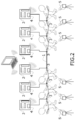
- Figure 2 shows two teams of players pulling in opposite directions on a rope or cable wherein thanks to the vibration frequency measuring sensors (2) attached externally on the rope or cable it is possible to obtain over time the individual force profiles of each player, and the force profile of each team.
- opposite each vibration frequency measuring sensor (2) there is a camera (5).
- the means of measuring the vibration frequency are arranged on the rope or cable and preferably just before the gripping point of each player, thus enabling the profile and intensity of the force exerted by each player to be determined.
- the means for measuring vibration frequency are triaxial accelerometers and are provided with means for wireless transmission (4) of the measured values to a computer or external means of processing.
- the force exerted at each point is calculated from the vibration frequency of the section in which that point is located, the length of that section and the density of the rope or cable.
- the rope or cable in addition to having the means for measuring the vibration frequency, can have cameras (5), as shown in Figure 3 , which in the embodiment shown comprise at least two cameras, a first camera (5) and a second camera (6), perpendicular to the pull, such that they 'see' the vibration to which the rope is subjected, due to their high resolution and speed.
Landscapes
- Health & Medical Sciences (AREA)
- Physical Education & Sports Medicine (AREA)
- General Physics & Mathematics (AREA)
- Life Sciences & Earth Sciences (AREA)
- Biophysics (AREA)
- Orthopedic Medicine & Surgery (AREA)
- General Health & Medical Sciences (AREA)
- Physics & Mathematics (AREA)
- Chemical & Material Sciences (AREA)
- Analytical Chemistry (AREA)
- Force Measurement Appropriate To Specific Purposes (AREA)
- Ropes Or Cables (AREA)
- Communication Cables (AREA)
Abstract
The object of the present invention is a rope or cable provided with vibration frequency meters which enable the individual and joint efforts made on a rope or similar to be measured from the values transmitted by the vibration frequency meters. It is a characteristic of the invention that a series of vibration frequency meters are secured or attached on a rope or cable, thus achieving what has been called a digital rope, that is to say, a rope that enables the individual efforts exerted in each zone and the joint effort to be determined.
Description
- As stated in the title of the invention, the object of the present invention is a rope or cable provided with vibration frequency meters which enable the individual and joint efforts made on a rope or similar to be measured from the values transmitted by the vibration frequency meters.
- It is a characteristic of the invention that a series of vibration frequency meters are secured or attached on a rope or cable, thus achieving what has been called a digital rope, that is to say, a rope that enables the individual efforts exerted in each zone and the joint effort to be determined.
- The rope that forms the object of the invention is for use primarily, but not restrictively, for the game of tug-of-war (tug of war, tug o' war, tug war, rope war, rope pulling, or tugging war) in which two teams with the same number of members, with a combined weight not exceeding the maximum specified weight for a given category, line up at either end of a rope facing each other, each team pulling in opposite directions. The rope that forms the object of the invention determines the profiles of the force exerted by each member of each team and by the team as a whole.
- The present invention therefore pertains on the one hand, to means for measuring tension in cables and similar, and on the other hand, to the ambit of ropes.
- In the prior art, the use of diverse sensors fitted to cables and elements subjected to tension for the purposes of determining the tension to which said cables are subjected is well known.
- In the prior art, smart ropes housing a number of sensors, such as those described in patents
WO2017043692 ,CN201689345U ,US20150265869 , are well known. The existence of digital ropes, such as those described in patentsUS5662561 andUS8123586 , is also known. Publications also exist disclosing accelerometers housed inside the ropes such as those described in patentsCN103998367B andEP2197775 . Other cables seek to estimate the sway suffered by an elevator, as described in patentUS20130275081 , or to control the tension in a rope between two points,US20150008075 . Patents also exist that seek to measure the tension to which the ropes are subjected, such as patentsUS6901818 ,DE20201105186U1 ,US4171640 ,CN101319946A ,US6123176 ,CA2395373 . - None of the above documents disclose systems or ropes that measure tension in a rope or cable based on vibration frequency.
- However, when a cable or rope is subjected to individually apply tensile forces, it has been seen to be necessary to determine the force or tension profile to which each zone is subjected, in order that the overall force profile of the entire cable or rope can subsequently be ascertained.
- The object of the present invention is therefore to develop a rope or similar in a digitalised manner that enables the individual forces applied to the rope to be determined, on the basis of the frequency of vibration of the tension exerted on the rope, by developing a rope or cable such as that described hereinafter, whose essentiality is set out in the first claim.
- The object of the present invention is a digitalised rope or cable on which are arranged a series of positionable means of measuring the vibration frequency of the rope.
- In one possible embodiment such means for measuring the vibration frequency may be triaxial accelerometers.
- The means for measuring the vibration frequency are positionable means, i.e. means that can be fixed on the rope wherever best suits, and a series of clamps can be used to secure them.
- The means for measuring the vibration frequency also have means of wireless transmission to means of processing external to the rope or cable. It is thus possible to ascertain the force exerted, its profile, and intensity by each user positioned just after each vibration frequency meter, and the joint force exerted by a team.
- The means for measuring the frequency are regularly arranged in certain positions, preferably before the gripping point on the rope -in relation to the direction in which the force is exerted- so that the force exerted at that point by a user or external force can be determined.
- Complementarily, in order to obtain additional information about the displacement of the rope in one direction or another, it may have a system of cameras associated with each vibration frequency measurement sensor to measure the distance or displacement of the rope.
- In one possible embodiment, the cameras are high-resolution, high-speed cameras located perpendicular to the rope and are used for:
- a) estimating the distance of the rope between two pullers that is not touching either of them
- b) capturing also the frequency at which the rope vibrates, which is possible due to its high speed.
- a) to validate the two measurements, if they are sufficiently similar, or to detect errors of measurement errors, if the result is significantly different, and also
- b) to reinforce the system of measurement, since it will act as a parallel system that will continue to function in the event that one of the two techniques, camera or accelerometer, ceases to operate.
- The vibration frequency measuring sensors are triaxial accelerometers which measure the frequency of vibrations in both the vertical and horizontal axis of the rope or cable. The reason for measuring the vibration frequency on the horizontal axis is to measure the acceleration in motion, which can provide information to contrast that of the tension coming from the frequency.
- Unless otherwise indicated, all technical and scientific elements used in this specification have the meaning habitually understood by a person skilled in the art to which this invention pertains. In the practice of the present invention, similar or equivalent procedures and materials to those described in the record can be used.
- Throughout the description and the claims, the words "contains" or "comprises" and its variants are not intended to exclude other technical characteristics, additives, components or steps. For experts in the field, other objects, advantages and characteristics of the invention will emerge partly from the description and partly from practice with the invention.
- To complete the description made herein and in order better to aid understanding of the characteristics of the invention, in accordance with a preferential example of a practical embodiment thereof, this description is accompanied by a set of drawings showing as follows in indicative, but not restrictive terms.
-
Figure 1 shows a representation of a rope on which two people are pulling in opposite directions. -
Figure 2 shows an example of an arrangement of two teams pulling a rope in opposite directions, depicting measuring sensors removably attached to the rope or cable and a series of cameras arranged opposite each sensor. -
Figure 3 shows a rope on which a camera has been placed transversely on each side. - As per the figures, one preferred embodiment of the proposed invention is described below.
-
Figure 1 shows a rope or cable (1) on which two persons are pulling in opposite directions and on which vibration frequency measuring sensors (2) are positionably fixed to the rope or cable, in one possible embodiment, by means of clamps (3). - In other words, the vibration frequency measurement sensors can be placed wherever best suits on the rope or cable.
-
Figure 2 shows two teams of players pulling in opposite directions on a rope or cable wherein thanks to the vibration frequency measuring sensors (2) attached externally on the rope or cable it is possible to obtain over time the individual force profiles of each player, and the force profile of each team. In this figure one can observe that opposite each vibration frequency measuring sensor (2) there is a camera (5). - As can be seen the means of measuring the vibration frequency are arranged on the rope or cable and preferably just before the gripping point of each player, thus enabling the profile and intensity of the force exerted by each player to be determined.
- In one possible embodiment, the means for measuring vibration frequency are triaxial accelerometers and are provided with means for wireless transmission (4) of the measured values to a computer or external means of processing.
- In one possible non-restrictive embodiment, the force exerted at each point is calculated from the vibration frequency of the section in which that point is located, the length of that section and the density of the rope or cable.

- S is the tension in the rope.
- L is the length of each length of rope or cable, between one puller and the next.
- f1 is the vibration frequency of that section.
- µ is the mass per unit of length of the rope.
- Complementarily, the rope or cable, in addition to having the means for measuring the vibration frequency, can have cameras (5), as shown in
Figure 3 , which in the embodiment shown comprise at least two cameras, a first camera (5) and a second camera (6), perpendicular to the pull, such that they 'see' the vibration to which the rope is subjected, due to their high resolution and speed. - In its application to the game of tug-of-war this would make it possible to determine the weak points of each team, those places where improvements might be made and what the most suitable type of force to be exerted in each competition would be.
- Having sufficiently described the nature of the present invention, and the means of implementing it, it is noted that within the same essentiality, it may be made in other embodiments differing in detail from that indicated herein as an example, and to which the protection obtained shall equally extend, provided that it does not alter, change or modify its basic principle.
Claims (7)
- A digitalised rope or cable characterised in that it comprises a series of positionable means on the rope for measuring the vibration frequency of the rope, wherein each of the positionable means for measuring the vibration frequency has means of wireless transmission (4) to external means of processing.
- A digitalised rope or cable according to Claim 1 characterised in that in one possible embodiment said means for measuring the vibration frequency are triaxial accelerometers.
- A digitalised rope or cable according to Claim 2 characterised in that the triaxial accelerometers measure the frequency of vibrations in both the vertical and horizontal axis of the rope or cable.
- A digitalised rope or cable according to Claim 1 or 2 or 3 characterised in that additionally the rope has high resolution and high-speed cameras located perpendicular to the rope and they serve to:a) enable the distance of the rope between two pullers that is not touching either of them to be determinedb) enable also the frequency at which the rope vibrates to be determined, which is possible due to their high speed.
- A digitalised rope or cable according to Claim 1 or 2 or 3 characterised in that each vibration frequency measurement device (2) comprises at least two cameras, a first camera (5) and a second camera (6), perpendicular to the direction of pull, such that they see the vibration to which the rope is subjected, due to their high resolution and speed.
- A digitized rope or cable according to any of the above claims, characterised in that the force exerted at each point is calculated from the vibration frequency of the section in which that point is located, the length of that section and the density of the rope or cable.
 S is the tension in the rope.L is the length of each length of rope or cable, between one puller and the next.f1 is the vibration frequency of said section.µ is the mass per unit of length of the rope.
 - A digitalised rope or cable according to any of the above claims, characterised in that the means for measuring the vibration frequency are positionably attached to the rope or cable by means of a clamp (3).
Applications Claiming Priority (1)
| Application Number | Priority Date | Filing Date | Title |
|---|---|---|---|
| ES202330339U ES1299776Y (en) | 2023-03-02 | 2023-03-02 | ROPE OR CABLE WITH VIBRATION FREQUENCY METERS |
Publications (1)
| Publication Number | Publication Date |
|---|---|
| EP4425136A1 true EP4425136A1 (en) | 2024-09-04 |
Family
ID=86327260
Family Applications (1)
| Application Number | Title | Priority Date | Filing Date |
|---|---|---|---|
| EP24159586.7A Withdrawn EP4425136A1 (en) | 2023-03-02 | 2024-02-26 | Rope or cable with vibration frequency meters |
Country Status (2)
| Country | Link |
|---|---|
| EP (1) | EP4425136A1 (en) |
| ES (1) | ES1299776Y (en) |
Citations (19)
| Publication number | Priority date | Publication date | Assignee | Title |
|---|---|---|---|---|
| US4171640A (en) | 1978-05-16 | 1979-10-23 | W. C. Dillon And Company, Inc. | Tension measuring device |
| US5454272A (en) * | 1994-02-07 | 1995-10-03 | Ihs Engineering, Inc. | Cable tensioning device |
| US5662561A (en) | 1995-02-22 | 1997-09-02 | Mcnamara; Thomas | Weighted handle for a jump rope |
| US6123176A (en) | 1996-05-28 | 2000-09-26 | Otis Elevator Company | Rope tension monitoring assembly and method |
| CA2395373A1 (en) | 1999-12-23 | 2001-06-28 | Kyle Geoffrey Thomas | Tension control in a rope-making machine |
| US6901818B1 (en) | 2002-12-05 | 2005-06-07 | Maxwell C. Cheung | Tension measuring device for mooring line |
| DE19531858B4 (en) * | 1995-08-30 | 2005-06-09 | Deutsche Telekom Ag | Measuring method for guy ropes |
| CN101319946A (en) | 2008-06-30 | 2008-12-10 | 上海都峰智能科技有限公司 | Three bar single order type tension measurement method |
| EP2197775A2 (en) | 2007-09-14 | 2010-06-23 | Thyssenkrupp Elevator Capital Corporation | System and method to minimize rope sway in elevators |
| CN201689345U (en) | 2010-02-10 | 2010-12-29 | 杭州舒瑞环境科技有限公司 | Buoy pull rope type water tank liquid-level intelligent monitor |
| DE202011005186U1 (en) | 2011-04-12 | 2011-11-30 | Abelardo Schott Garcia, gesetzlich vertreten durch Karl-Helmut Schott | Motor vehicle with at least two connected by coupling internal combustion engines |
| US8123586B2 (en) | 2007-04-28 | 2012-02-28 | Dell Electronics Laboratories, Ltd. | Electronic jump rope |
| US20130275081A1 (en) | 2012-04-13 | 2013-10-17 | Mouhacine Benosman | Elevator Rope Sway Estimation |
| CN103998367A (en) | 2011-09-20 | 2014-08-20 | 科恩起重机有限公司 | Crane control |
| US20150008075A1 (en) | 2013-07-02 | 2015-01-08 | Mitsubishi Electric Corporation | Controlling Sway of Elevator Rope Using Movement of Elevator Car |
| US20150265869A1 (en) | 2014-03-19 | 2015-09-24 | Patrick Hemstreet | Battle Rope Training Device |
| WO2017043692A1 (en) | 2015-09-11 | 2017-03-16 | 주식회사 탱그램팩토리 | Smart rope with multi-layered skipping rope for protecting led |
| EP3885487A1 (en) * | 2020-02-14 | 2021-09-29 | Universidad De La Iglesia De Deusto | Digitalised rope or cable |
| CN113607321A (en) * | 2021-07-16 | 2021-11-05 | 重庆物康科技有限公司 | Cable force testing method and device of cable structure, computer equipment and storage medium |
-
2023
- 2023-03-02 ES ES202330339U patent/ES1299776Y/en active Active
-
2024
- 2024-02-26 EP EP24159586.7A patent/EP4425136A1/en not_active Withdrawn
Patent Citations (19)
| Publication number | Priority date | Publication date | Assignee | Title |
|---|---|---|---|---|
| US4171640A (en) | 1978-05-16 | 1979-10-23 | W. C. Dillon And Company, Inc. | Tension measuring device |
| US5454272A (en) * | 1994-02-07 | 1995-10-03 | Ihs Engineering, Inc. | Cable tensioning device |
| US5662561A (en) | 1995-02-22 | 1997-09-02 | Mcnamara; Thomas | Weighted handle for a jump rope |
| DE19531858B4 (en) * | 1995-08-30 | 2005-06-09 | Deutsche Telekom Ag | Measuring method for guy ropes |
| US6123176A (en) | 1996-05-28 | 2000-09-26 | Otis Elevator Company | Rope tension monitoring assembly and method |
| CA2395373A1 (en) | 1999-12-23 | 2001-06-28 | Kyle Geoffrey Thomas | Tension control in a rope-making machine |
| US6901818B1 (en) | 2002-12-05 | 2005-06-07 | Maxwell C. Cheung | Tension measuring device for mooring line |
| US8123586B2 (en) | 2007-04-28 | 2012-02-28 | Dell Electronics Laboratories, Ltd. | Electronic jump rope |
| EP2197775A2 (en) | 2007-09-14 | 2010-06-23 | Thyssenkrupp Elevator Capital Corporation | System and method to minimize rope sway in elevators |
| CN101319946A (en) | 2008-06-30 | 2008-12-10 | 上海都峰智能科技有限公司 | Three bar single order type tension measurement method |
| CN201689345U (en) | 2010-02-10 | 2010-12-29 | 杭州舒瑞环境科技有限公司 | Buoy pull rope type water tank liquid-level intelligent monitor |
| DE202011005186U1 (en) | 2011-04-12 | 2011-11-30 | Abelardo Schott Garcia, gesetzlich vertreten durch Karl-Helmut Schott | Motor vehicle with at least two connected by coupling internal combustion engines |
| CN103998367A (en) | 2011-09-20 | 2014-08-20 | 科恩起重机有限公司 | Crane control |
| US20130275081A1 (en) | 2012-04-13 | 2013-10-17 | Mouhacine Benosman | Elevator Rope Sway Estimation |
| US20150008075A1 (en) | 2013-07-02 | 2015-01-08 | Mitsubishi Electric Corporation | Controlling Sway of Elevator Rope Using Movement of Elevator Car |
| US20150265869A1 (en) | 2014-03-19 | 2015-09-24 | Patrick Hemstreet | Battle Rope Training Device |
| WO2017043692A1 (en) | 2015-09-11 | 2017-03-16 | 주식회사 탱그램팩토리 | Smart rope with multi-layered skipping rope for protecting led |
| EP3885487A1 (en) * | 2020-02-14 | 2021-09-29 | Universidad De La Iglesia De Deusto | Digitalised rope or cable |
| CN113607321A (en) * | 2021-07-16 | 2021-11-05 | 重庆物康科技有限公司 | Cable force testing method and device of cable structure, computer equipment and storage medium |
Also Published As
| Publication number | Publication date |
|---|---|
| ES1299776U (en) | 2023-05-18 |
| ES1299776Y (en) | 2023-08-08 |
Similar Documents
| Publication | Publication Date | Title |
|---|---|---|
| US5233139A (en) | Measurement of traction, operation of brake, friction safety gear, and cable forces of an elevator | |
| CN102037341A (en) | System and procedure for the real-time monitoring of fixed or mobile rigid structures such as building structures, aircraft, ships and/or the like | |
| US6923065B2 (en) | Apparatus for testing aramid fiber elevator cables | |
| Eppinger | On the development of a deformation measurement system and its application toward developing mechanically based injury indices | |
| US20220291078A1 (en) | Measurement Method, Measurement Device, Measurement System, And Measurement Program | |
| JP5790586B2 (en) | Elevator rope tension measuring method and apparatus | |
| US6662660B2 (en) | Apparatus for testing aramid fiber elevator cables | |
| JP2984337B2 (en) | Optical fiber underwater temperature distribution measurement system | |
| US4240289A (en) | Mass and force meter | |
| KR100972278B1 (en) | Measuring method and measuring device for measuring dynamic displacement and speed history using the vibration acceleration of structures | |
| JP3956302B2 (en) | Damaged part detection device for structure and method for detecting damaged part of structure | |
| KR101284125B1 (en) | Movable measuring system for measuring dynamic responses of the bridges | |
| CN105984773B (en) | Rope load detecting device for detecting total load of a plurality of elevator ropes | |
| JP4033119B2 (en) | Material testing method, material testing machine | |
| EP2753910B1 (en) | Method&apparatus for measuring work index | |
| EP2746207B1 (en) | Elevator arrangement and method of computing control information for elevator | |
| Nikolayev et al. | Fiber optic sensors for parachute systems monitoring | |
| CN112395697B (en) | Method for obtaining damping coefficient of flexible rope of parachute | |
| Szade et al. | Measurements of rope elongation or deflection in impact destructive testing | |
| EP3885487A1 (en) | Digitalised rope or cable | |
| JPS6013207A (en) | Method for measuring elongation strain using optical fiber | |
| RU2743778C1 (en) | Method for determining the non-stationary force and a device for its implementation | |
| JP3969558B2 (en) | Method and apparatus for measuring wave propagation velocity of overhead wire | |
| ES1299776U (en) | ROPE OR CABLE WITH VIBRATION FREQUENCY METERS (Machine-translation by Google Translate, not legally binding) | |
| JP3052563U (en) | Measuring device for contact pressure between cable support ring and pressure receiving ring |
Legal Events
| Date | Code | Title | Description |
|---|---|---|---|
| PUAI | Public reference made under article 153(3) epc to a published international application that has entered the european phase |
Free format text: ORIGINAL CODE: 0009012 |
|
| STAA | Information on the status of an ep patent application or granted ep patent |
Free format text: STATUS: THE APPLICATION HAS BEEN PUBLISHED |
|
| AK | Designated contracting states |
Kind code of ref document: A1 Designated state(s): AL AT BE BG CH CY CZ DE DK EE ES FI FR GB GR HR HU IE IS IT LI LT LU LV MC ME MK MT NL NO PL PT RO RS SE SI SK SM TR |
|
| STAA | Information on the status of an ep patent application or granted ep patent |
Free format text: STATUS: THE APPLICATION IS DEEMED TO BE WITHDRAWN |
|
| 18D | Application deemed to be withdrawn |
Effective date: 20250305 |