EP4425065A1 - Control method for air source heat pump unit system and air source heat pump unit system - Google Patents
Control method for air source heat pump unit system and air source heat pump unit system Download PDFInfo
- Publication number
- EP4425065A1 EP4425065A1 EP22885232.3A EP22885232A EP4425065A1 EP 4425065 A1 EP4425065 A1 EP 4425065A1 EP 22885232 A EP22885232 A EP 22885232A EP 4425065 A1 EP4425065 A1 EP 4425065A1
- Authority
- EP
- European Patent Office
- Prior art keywords
- temperature
- air source
- water
- heat pump
- source heat
- Prior art date
- Legal status (The legal status is an assumption and is not a legal conclusion. Google has not performed a legal analysis and makes no representation as to the accuracy of the status listed.)
- Granted
Links
Images



Classifications
-
- F—MECHANICAL ENGINEERING; LIGHTING; HEATING; WEAPONS; BLASTING
- F24—HEATING; RANGES; VENTILATING
- F24F—AIR-CONDITIONING; AIR-HUMIDIFICATION; VENTILATION; USE OF AIR CURRENTS FOR SCREENING
- F24F11/00—Control or safety arrangements
- F24F11/30—Control or safety arrangements for purposes related to the operation of the system, e.g. for safety or monitoring
- F24F11/46—Improving electric energy efficiency or saving
-
- F—MECHANICAL ENGINEERING; LIGHTING; HEATING; WEAPONS; BLASTING
- F24—HEATING; RANGES; VENTILATING
- F24D—DOMESTIC- OR SPACE-HEATING SYSTEMS, e.g. CENTRAL HEATING SYSTEMS; DOMESTIC HOT-WATER SUPPLY SYSTEMS; ELEMENTS OR COMPONENTS THEREFOR
- F24D19/00—Details
- F24D19/10—Arrangement or mounting of control or safety devices
- F24D19/1006—Arrangement or mounting of control or safety devices for water heating systems
- F24D19/1009—Arrangement or mounting of control or safety devices for water heating systems for central heating
- F24D19/1012—Arrangement or mounting of control or safety devices for water heating systems for central heating by regulating the speed of a pump
-
- F—MECHANICAL ENGINEERING; LIGHTING; HEATING; WEAPONS; BLASTING
- F24—HEATING; RANGES; VENTILATING
- F24D—DOMESTIC- OR SPACE-HEATING SYSTEMS, e.g. CENTRAL HEATING SYSTEMS; DOMESTIC HOT-WATER SUPPLY SYSTEMS; ELEMENTS OR COMPONENTS THEREFOR
- F24D3/00—Hot-water central heating systems
- F24D3/18—Hot-water central heating systems using heat pumps
-
- F—MECHANICAL ENGINEERING; LIGHTING; HEATING; WEAPONS; BLASTING
- F24—HEATING; RANGES; VENTILATING
- F24F—AIR-CONDITIONING; AIR-HUMIDIFICATION; VENTILATION; USE OF AIR CURRENTS FOR SCREENING
- F24F11/00—Control or safety arrangements
- F24F11/30—Control or safety arrangements for purposes related to the operation of the system, e.g. for safety or monitoring
-
- F—MECHANICAL ENGINEERING; LIGHTING; HEATING; WEAPONS; BLASTING
- F24—HEATING; RANGES; VENTILATING
- F24F—AIR-CONDITIONING; AIR-HUMIDIFICATION; VENTILATION; USE OF AIR CURRENTS FOR SCREENING
- F24F11/00—Control or safety arrangements
- F24F11/62—Control or safety arrangements characterised by the type of control or by internal processing, e.g. using fuzzy logic, adaptive control or estimation of values
- F24F11/63—Electronic processing
- F24F11/64—Electronic processing using pre-stored data
-
- F—MECHANICAL ENGINEERING; LIGHTING; HEATING; WEAPONS; BLASTING
- F24—HEATING; RANGES; VENTILATING
- F24F—AIR-CONDITIONING; AIR-HUMIDIFICATION; VENTILATION; USE OF AIR CURRENTS FOR SCREENING
- F24F11/00—Control or safety arrangements
- F24F11/70—Control systems characterised by their outputs; Constructional details thereof
- F24F11/80—Control systems characterised by their outputs; Constructional details thereof for controlling the temperature of the supplied air
- F24F11/83—Control systems characterised by their outputs; Constructional details thereof for controlling the temperature of the supplied air by controlling the supply of heat-exchange fluids to heat-exchangers
-
- F—MECHANICAL ENGINEERING; LIGHTING; HEATING; WEAPONS; BLASTING
- F24—HEATING; RANGES; VENTILATING
- F24F—AIR-CONDITIONING; AIR-HUMIDIFICATION; VENTILATION; USE OF AIR CURRENTS FOR SCREENING
- F24F11/00—Control or safety arrangements
- F24F11/70—Control systems characterised by their outputs; Constructional details thereof
- F24F11/80—Control systems characterised by their outputs; Constructional details thereof for controlling the temperature of the supplied air
- F24F11/83—Control systems characterised by their outputs; Constructional details thereof for controlling the temperature of the supplied air by controlling the supply of heat-exchange fluids to heat-exchangers
- F24F11/84—Control systems characterised by their outputs; Constructional details thereof for controlling the temperature of the supplied air by controlling the supply of heat-exchange fluids to heat-exchangers using valves
-
- F—MECHANICAL ENGINEERING; LIGHTING; HEATING; WEAPONS; BLASTING
- F24—HEATING; RANGES; VENTILATING
- F24H—FLUID HEATERS, e.g. WATER OR AIR HEATERS, HAVING HEAT-GENERATING MEANS, e.g. HEAT PUMPS, IN GENERAL
- F24H15/00—Control of fluid heaters
- F24H15/10—Control of fluid heaters characterised by the purpose of the control
- F24H15/156—Reducing the quantity of energy consumed; Increasing efficiency
-
- F—MECHANICAL ENGINEERING; LIGHTING; HEATING; WEAPONS; BLASTING
- F24—HEATING; RANGES; VENTILATING
- F24H—FLUID HEATERS, e.g. WATER OR AIR HEATERS, HAVING HEAT-GENERATING MEANS, e.g. HEAT PUMPS, IN GENERAL
- F24H15/00—Control of fluid heaters
- F24H15/10—Control of fluid heaters characterised by the purpose of the control
- F24H15/174—Supplying heated water with desired temperature or desired range of temperature
- F24H15/175—Supplying heated water with desired temperature or desired range of temperature where the difference between the measured temperature and a set temperature is kept under a predetermined value
-
- F—MECHANICAL ENGINEERING; LIGHTING; HEATING; WEAPONS; BLASTING
- F24—HEATING; RANGES; VENTILATING
- F24H—FLUID HEATERS, e.g. WATER OR AIR HEATERS, HAVING HEAT-GENERATING MEANS, e.g. HEAT PUMPS, IN GENERAL
- F24H15/00—Control of fluid heaters
- F24H15/20—Control of fluid heaters characterised by control inputs
- F24H15/212—Temperature of the water
-
- F—MECHANICAL ENGINEERING; LIGHTING; HEATING; WEAPONS; BLASTING
- F24—HEATING; RANGES; VENTILATING
- F24H—FLUID HEATERS, e.g. WATER OR AIR HEATERS, HAVING HEAT-GENERATING MEANS, e.g. HEAT PUMPS, IN GENERAL
- F24H15/00—Control of fluid heaters
- F24H15/20—Control of fluid heaters characterised by control inputs
- F24H15/254—Room temperature
-
- F—MECHANICAL ENGINEERING; LIGHTING; HEATING; WEAPONS; BLASTING
- F24—HEATING; RANGES; VENTILATING
- F24H—FLUID HEATERS, e.g. WATER OR AIR HEATERS, HAVING HEAT-GENERATING MEANS, e.g. HEAT PUMPS, IN GENERAL
- F24H15/00—Control of fluid heaters
- F24H15/30—Control of fluid heaters characterised by control outputs; characterised by the components to be controlled
- F24H15/335—Control of pumps, e.g. on-off control
- F24H15/34—Control of the speed of pumps
-
- F—MECHANICAL ENGINEERING; LIGHTING; HEATING; WEAPONS; BLASTING
- F24—HEATING; RANGES; VENTILATING
- F24H—FLUID HEATERS, e.g. WATER OR AIR HEATERS, HAVING HEAT-GENERATING MEANS, e.g. HEAT PUMPS, IN GENERAL
- F24H15/00—Control of fluid heaters
- F24H15/30—Control of fluid heaters characterised by control outputs; characterised by the components to be controlled
- F24H15/375—Control of heat pumps
-
- F—MECHANICAL ENGINEERING; LIGHTING; HEATING; WEAPONS; BLASTING
- F24—HEATING; RANGES; VENTILATING
- F24H—FLUID HEATERS, e.g. WATER OR AIR HEATERS, HAVING HEAT-GENERATING MEANS, e.g. HEAT PUMPS, IN GENERAL
- F24H4/00—Fluid heaters characterised by the use of heat pumps
- F24H4/02—Water heaters
-
- F—MECHANICAL ENGINEERING; LIGHTING; HEATING; WEAPONS; BLASTING
- F24—HEATING; RANGES; VENTILATING
- F24D—DOMESTIC- OR SPACE-HEATING SYSTEMS, e.g. CENTRAL HEATING SYSTEMS; DOMESTIC HOT-WATER SUPPLY SYSTEMS; ELEMENTS OR COMPONENTS THEREFOR
- F24D19/00—Details
- F24D19/10—Arrangement or mounting of control or safety devices
- F24D19/1006—Arrangement or mounting of control or safety devices for water heating systems
- F24D19/1009—Arrangement or mounting of control or safety devices for water heating systems for central heating
-
- F—MECHANICAL ENGINEERING; LIGHTING; HEATING; WEAPONS; BLASTING
- F24—HEATING; RANGES; VENTILATING
- F24D—DOMESTIC- OR SPACE-HEATING SYSTEMS, e.g. CENTRAL HEATING SYSTEMS; DOMESTIC HOT-WATER SUPPLY SYSTEMS; ELEMENTS OR COMPONENTS THEREFOR
- F24D2200/00—Heat sources or energy sources
- F24D2200/12—Heat pump
-
- Y—GENERAL TAGGING OF NEW TECHNOLOGICAL DEVELOPMENTS; GENERAL TAGGING OF CROSS-SECTIONAL TECHNOLOGIES SPANNING OVER SEVERAL SECTIONS OF THE IPC; TECHNICAL SUBJECTS COVERED BY FORMER USPC CROSS-REFERENCE ART COLLECTIONS [XRACs] AND DIGESTS
- Y02—TECHNOLOGIES OR APPLICATIONS FOR MITIGATION OR ADAPTATION AGAINST CLIMATE CHANGE
- Y02B—CLIMATE CHANGE MITIGATION TECHNOLOGIES RELATED TO BUILDINGS, e.g. HOUSING, HOUSE APPLIANCES OR RELATED END-USER APPLICATIONS
- Y02B30/00—Energy efficient heating, ventilation or air conditioning [HVAC]
- Y02B30/70—Efficient control or regulation technologies, e.g. for control of refrigerant flow, motor or heating
Definitions
- the present application relates to the technical field of heat pump unit equipment, and in particular, to a control method for an air source heat pump unit system and an air source heat pump unit system.
- An air source heat pump unit system has a wide range of applications. However, in actual engineering projects, it is generally based on a maximum heat load under a designed working condition to select a unit type of the air source heat pump unit, which may cause low energy efficiency of the unit. When working condition of outdoor temperature is improved, a room load may be reduced, which may lead to frequent frosting, false defrosting, and unstable operation of the air source heat pump unit system. Correspondingly, these phenomena may easily cause fluctuations of water temperature of the unit system, high operating energy consumption of the unit system and poor room comfort.
- the air source heat pump unit system in related technologies has a problem of high operating energy consumption and poor room comfort.
- the present application proposes a control method for an air source heat pump unit system and an air source heat pump unit system to solve the problem of high operating energy consumption of the air source heat pump unit system and poor room comfort.
- the control method for the air source heat pump unit system of the present application includes: controlling a supply water temperature of the air source heat pump unit system by monitoring a change in an actual demand at an end.
- control method includes:
- the method further includes:
- the method further includes: returning to the step of reducing the supply water temperature while ensuring the temperature difference of supply and return water remaining unchanged when the current temperature deviation value of the room fails to be higher than the temperature deviation threshold.
- the method further includes:
- control method further includes:
- the method further includes: returning to the step of adjusting the opening degree of the end valve and synchronously adjusting the rotary speed of the water pump to reduce the circulating water volume of the system when the current temperature deviation value of the room fails to be higher than the temperature deviation threshold.
- control method further includes:
- control method further includes:
- the present application provides an air source heat pump unit system.
- the air source heat pump unit system configured to adjust a temperature of a room, includes:
- the present application further provides a computer device, including a memory and a processor, the memory being configured to store a computer program.
- the processor is configured to execute the computer program to implement the steps of any one of the control methods for the air source heat pump unit system mentioned above.
- the present application further provides a non-transitory computer-readable storage medium storing a computer program.
- the computer program When the computer program is executed, the steps of any one of the control methods for the air source heat pump unit system mentioned above are implemented.
- control method for the air source heat pump unit system and the air source heat pump unit system provided in the present application possess at least the following beneficial effects.
- Heat pump unit 20. Water supply pipeline; 30. End heat exchanger; 40. Return water pipeline; 50. Water pump; 60. End valve.
- an end refers to a room heated by an air source heat pump unit system
- a change in an actual demand at the end in the present application includes a change of current temperature of the room mentioned above.
- the present application provides a control method for an air source heat pump unit system, including: controlling a supply water temperature of the air source heat pump unit system by monitoring a change in an actual demand at an end.
- an operating status of the air source heat pump unit system is adjusted, thereby reducing an actual supply water temperature of the air source heat pump unit system. Therefore, an operating energy consumption of the air source heat pump unit system is reduced, an operating efficiency of the system is improved, energy waste of the system is reduced, and a stable operation of the system is ensured. Furthermore, room comfort is improved, so as to provide a better experience to a user.
- the present application provides a control method for an air source heat pump unit system.
- the air source heat pump unit system is used to adjust a temperature of a room, and the control method for the air source heat pump unit system control method includes the following steps.
- Step 1 setting a target temperature T of a room and a temperature deviation threshold ⁇ T1;
- Step 2 setting a supply water temperature T1 and a return water temperature T2 of the air source heat pump unit system (Step 2 and Step 1 are combined together in FIG. 1 , and there is no sequential relationship between the two steps);
- Step 3 determining whether a current temperature deviation value of the room of the air source heat bump unit system is higher than the temperature deviation threshold ⁇ T1 of the air source heat bump unit system.
- the current temperature deviation value of the room is a difference between a current temperature of the room and the target temperature of the room.
- the temperature difference ⁇ T of supply and return water of the air source heat pump unit system is a difference between the supply water temperature T1 and the return water temperature T2, and the supply water temperature T1 is higher than the return water temperature T2 in the air source heat pump unit system.
- Embodiment 2 A difference between Embodiment 2 and Embodiment 1 will be described below.
- control method further includes the following step.
- Step 4 determining whether the current temperature deviation value of the room of the air source heat bump unit system is higher than the temperature deviation threshold ⁇ T1 of the air source heat bump unit system.
- the supply water temperature T1 of the air source heat bump unit system is continually reduced, the return water temperature T2 of the air source heat bump unit system is synchronously reduced, and the temperature difference ⁇ T of supply and return water is ensured remaining unchanged.
- the step of reducing the supply water temperature T1 of the air source heat pump unit system while ensuring the temperature difference ⁇ T of supply and return water of the air source heat pump unit system remaining unchanged is returned.
- Embodiment 2 The other steps in Embodiment 2 are the same as those in Embodiment 1, and will not be repeated here.
- Embodiment 3 A difference between Embodiment 3 and Embodiment 2 will be described below.
- control method further includes the following step.
- Step 5 determining whether the current temperature deviation value of the room of the air source heat bump unit system is higher than the temperature deviation threshold ⁇ T1 of the air source heat bump unit system when the supply water temperature T1 of the air source heat bump unit system is lower than a lower limit temperature.
- the step of continually reducing the supply water temperature T1, synchronously reducing the return water temperature T2, and ensuring the temperature difference ⁇ T of supply and return water remaining unchanged is returned.
- the circulating water volume of the system is reduced.
- an operating energy consumption of the air source heat pump unit system is reduced, an operating efficiency of the system is improved, energy waste of the system is reduced, and a stable operation of the system is ensured.
- room comfort is improved, so as to provide a better experience to a user.
- the rotary speed of the water pump is synchronously adjusted through interlock in the present application refers to that the rotary speed of the water pump only can be adjusted when the opening degree of the end valve starts to be adjusted.
- Embodiment 3 The other steps in Embodiment 3 are the same as those in Embodiment 2, and will not be repeated here.
- Embodiment 4 A difference between Embodiment 4 and Embodiment 3 will be described below.
- control method further includes the following step.
- Step 6 determining whether the current temperature deviation value of the room of the air source heat bump unit system is higher than the temperature deviation threshold ⁇ T1 of the air source heat bump unit system when the rotary speed of the water pump is determined to reach a lower limit value.
- a unit is turned off (that is, a heat pump unit is turned off), and the water pump is operated at a low frequency to maintain water circulation of the system.
- the step of adjusting the opening degree of the end valve and synchronously adjusting the rotary speed of the water pump through interlock to reduce the circulating water volume of the system is returned.
- Embodiment 4 The other steps in Embodiment 4 are the same as those in Embodiment 3, and will not be repeated here.
- control method further includes the following step.
- Step 7 determining whether the temperature difference ⁇ T of supply and return water becomes smaller.
- Embodiment 5 The other steps in Embodiment 5 are the same as those in Embodiment 4, and will not be repeated here.
- Embodiment 6 A difference between Embodiment 6 and Embodiment 5 will be described below.
- control method further includes the following step.
- Step 8 determining whether the current temperature deviation value of the room of the air source heat bump unit system is lower than the temperature deviation threshold ⁇ T1 of the air source heat bump unit system.
- Embodiment 6 The other steps in Embodiment 6 are the same as those in Embodiment 5, and will not be repeated here.
- the present application further provides an air source heat pump unit system.
- the air source heat pump unit system adopts the control method mentioned above to adjust a temperature of a room.
- the air source heat pump unit system includes a heat pump unit 10, a water supply pipeline 20, an end heat exchanger 30, a return water pipeline 40, a water pump 50, and an end valve 60.
- One end of the water supply pipeline 20 is connected to an output of the heat pump unit 10; an input of the end heat exchanger 30 is connected to the other end of the water supply pipeline 20; one end of the return water pipeline 40 is connected to the input of the heat pump unit 10; and the other end is connected to an output of the end heat exchanger 30.
- the water pump 50 is disposed on the return water pipeline 40, and the end valve 60 is disposed on the supply water pipeline 20.
- the water pump 50 cooperates with the end valve 60 to adjust a circulating water volume of the air source heat pump unit system.
- a supply water temperature, a return water temperature, and the circulating water volume of the air source heat pump unit system an operation efficiency of the air source heat pump unit system is improved.
- the heat pump unit 10 and the water pump 50 in the present application adopt variable frequency control.
- the change of the room load is predicted, and then the supply water temperature of the system and the operating status of the water pump are timely adjusted. That is, the water temperature of the system is adjusted based on the change of the room load. Therefore, the operating efficiency of the system is improved, the energy waste of the system is reduced, and the stable operation of the system is ensured. Furthermore, the room comfort is improved.
- a unit is controlled by setting the supply water temperature. When temperature of the room reaches a set value, the unit may start and stop frequently. In the present application, the supply water temperature of the unit is controlled by monitoring a change in an actual demand at the end. Therefore, the problem in an application of the conventional frequency conversion system may be solved by adjusting the supply water temperature of the unit. For example, when the room load is reduced, by reducing the supply water temperature of the unit, the frequent start and stop phenomena caused by the change of the room load may be relieved. Therefore, system stability and comprehensive energy efficiency is improved. Meanwhile, when the room load continues to decrease, the circulating water volume of the system may be further reduced, thereby reducing an energy consumption of the water pump and reducing an energy consumption of the system.
- the present application provides an air source heat pump unit system, including: a variable frequency air source heat pump unit, a variable frequency delivery water pump, an end heat exchanger 30, a circulating pipeline (including a return water pipeline 40 and a water supply pipeline 20), a temperature sensor, and an electric control valve (i.e., an end valve 60), etc.
- variable frequency air source heat pump unit is used to absorb heat from air, increase the heat by driving the unit, and provide hot water at a suitable temperature to the end heat exchanger 30 for room heating.
- a heating temperature of a room is set to a suitable target temperature value T (that is, temperature of the room is adjusted).
- T a supply water temperature of the variable frequency air source heat pump unit
- T2 a return water temperature after room heat exchange changes to T2.
- a temperature difference of supply and return water of the variable frequency air source heat pump unit is ⁇ T (T1-T2).
- the delivery water pump is utilized to circulate hot water in a pipeline network. Due to correlation between an indoor heat load and various factors such as outdoor environment, personnel air conditioning usage habits, and a change in fresh air volume, when temperature of the outdoor environment changes, a room load will also change accordingly.
- variable frequency air source heat pump unit detects the return water temperature of the unit increases and maintains for a certain time period t1. At this time, by adjusting an operating status of the unit, an actual supply water temperature of the unit is reduced, and the temperature difference ⁇ T of supply and return water remains unchanged to reduce an operating energy consumption of the unit. If the temperature of the room is still higher than the temperature deviation threshold ⁇ T1, the supply water temperature of the unit may still be reduced continuously.
- an adjustment method of the unit is to control a rotary speed of a compressor through frequency conversion, and synchronously reduce the return water temperature of the unit while maintaining the temperature difference ⁇ T of supply and return water unchanged.
- a valve i.e., an opening degree of an electric control valve
- variable frequency delivery water pump When the rotary speed of the variable frequency delivery water pump reaches a lower limit value (that is, a rotary speed corresponds to a significant decrease of efficiency of the water pump), and maintains for a certain time period t3, and the temperature of the room is still higher than the temperature deviation threshold ⁇ T1, at this time, the variable frequency air source heat pump unit is turned off, while the variable frequency delivery water pump continues to operate at a lowest allowable frequency to maintain water circulation of the system.
- a lower limit value that is, a rotary speed corresponds to a significant decrease of efficiency of the water pump
- variable frequency air source heat pump unit and the variable frequency delivery water pump are turned off, and the temperature of the room is detected to be lower than the temperature deviation threshold ⁇ T1 and maintain for a certain time period t5, the variable frequency delivery water pump and the variable frequency air source heat pump unit are restarted for heating. Meanwhile, during the adjustment process of the system, if the temperature of the room drops and falls below a lower limit of a preset room temperature deviation value, the unit frequency reduction control will be stopped, and an operating frequency of the unit will be appropriately increased to increase the temperature of the room. This loop control achieves an improvement in system efficiency.
- control method may improve an efficiency of the variable frequency air source heat pump unit, reduce frequent start and stop, reduce usage faults, and prolong a service life of the compressor by reducing the temperature of the supply water of hot water preferentially. Meanwhile, a frequency of fluctuation of the temperature of the room may be reduced, room comfort at the end may be maintained, and the waste of room heat may be reduced. In addition, by adjusting a flow rate of the system through the variable frequency delivery water pump, the energy consumption of the water pump may be reduced, and a comprehensive operating efficiency of the system may be improved.
- the air source heat pump unit system and the control method therefor in the present application have the following advantages.
- the present application further provides a computer device, including a memory and a processor, the memory being configured to store a computer program.
- the processor is configured to execute the computer program to implement the steps of any one of the control methods for the air source heat pump unit system mentioned above.
- the present application further provides a non-transitory computer-readable storage medium storing a computer program.
- the computer program is executed by a processor to implement the steps of any one of the control methods for the air source heat pump unit system mentioned above.
- any reference to memory, storage, database, or other media used in the embodiments provided in the present application may include at least one of non-volatile and volatile memory.
- the non-volatile memory may include a Read-Only Memory (ROM), a magnetic tape, a floppy disk, a flash memory, or an optical memory.
- the volatile memory may include a Random Access Memory (RAM) or an external cache memory.
- RAM may include various forms, such as a Static Random Access Memory (SRAM) or a Dynamic Random Access Memory (DRAM).
Landscapes
- Engineering & Computer Science (AREA)
- Chemical & Material Sciences (AREA)
- Combustion & Propulsion (AREA)
- Mechanical Engineering (AREA)
- General Engineering & Computer Science (AREA)
- Physics & Mathematics (AREA)
- Thermal Sciences (AREA)
- Signal Processing (AREA)
- Fuzzy Systems (AREA)
- Mathematical Physics (AREA)
- Air Conditioning Control Device (AREA)
Abstract
Description
- The application claims priority to Chinese Patent Application
CN202111276386.5, which is titled "CONTROL METHOD FOR AIR SOURCE HEAT PUMP UNIT SYSTEM AND AIR SOURCE HEAT PUMP UNIT SYSTEM" and submitted to the Chinese Patent Office on October 29, 2021 - The present application relates to the technical field of heat pump unit equipment, and in particular, to a control method for an air source heat pump unit system and an air source heat pump unit system.
- Currently, in distribution of various energy consumption of buildings, heating energy consumption accounts for a large proportion, which involves rational utilization of resources. It is necessary to increase utilization of renewable energy, such as air energy, to reduce environmental pollution. As a clean way of the utilization of energy, the air energy is utilized to improve indoor environment by heating and cooling. An air source heat pump unit system has a wide range of applications. However, in actual engineering projects, it is generally based on a maximum heat load under a designed working condition to select a unit type of the air source heat pump unit, which may cause low energy efficiency of the unit. When working condition of outdoor temperature is improved, a room load may be reduced, which may lead to frequent frosting, false defrosting, and unstable operation of the air source heat pump unit system. Correspondingly, these phenomena may easily cause fluctuations of water temperature of the unit system, high operating energy consumption of the unit system and poor room comfort.
- That is, the air source heat pump unit system in related technologies has a problem of high operating energy consumption and poor room comfort.
- In view of the problem in the prior art mentioned above, the present application proposes a control method for an air source heat pump unit system and an air source heat pump unit system to solve the problem of high operating energy consumption of the air source heat pump unit system and poor room comfort.
- The control method for the air source heat pump unit system of the present application includes:
controlling a supply water temperature of the air source heat pump unit system by monitoring a change in an actual demand at an end. - In an implementation, the control method includes:
- setting a target temperature of a room and a temperature deviation threshold;
- setting a supply water temperature and a return water temperature of the air source heat pump unit system;
- determining whether a current temperature deviation value of the room is higher than the temperature deviation threshold, where the current temperature deviation value of the room is a difference between a current temperature of the room and the target temperature of the room; and
- reducing the supply water temperature while ensuring a temperature difference of supply and return water remaining unchanged when the current temperature deviation value of the room is high than the temperature deviation threshold;
- where the temperature difference of supply and return water is a difference between the supply water temperature and the return water temperature, and the supply water temperature is higher than the return water temperature.
- In an implementation, the method further includes:
- determining whether the current temperature deviation value of the room is higher than the temperature deviation threshold; and
- continually reducing the supply water temperature, synchronously reducing the return water temperature, and ensuring the temperature difference of supply and return water remaining unchanged when the current temperature deviation value of the room is higher than the temperature deviation threshold. In this implementation method, by adjusting an operating status of the air source heat pump unit system, an actual supply water temperature and an actual return water temperature of the air source heat pump unit system are reduced and the temperature difference of supply and return water of the air source heat pump unit system remains unchanged. Therefore, operating energy consumption of the air source heat pump unit system is reduced, an operating efficiency of the system is improved, energy waste of the system is reduced, and a stable operation of the system is ensured. Furthermore, room comfort is improved, so as to provide a better experience to a user.
- In an implementation, the method further includes: returning to the step of reducing the supply water temperature while ensuring the temperature difference of supply and return water remaining unchanged when the current temperature deviation value of the room fails to be higher than the temperature deviation threshold.
- In an implementation, the method further includes:
- determining whether the current temperature deviation value of the room is higher than the temperature deviation threshold when the supply water temperature is lower than a lower limit temperature; and
- adjusting an opening degree of an end valve and synchronously adjusting a rotary speed of a water pump to reduce a circulating water volume of the system when the current temperature deviation value of the room is higher than the temperature deviation threshold. In this implementation method, by adjusting the operating status of the air source heat pump unit system, the circulating water volume of the system is reduced. Therefore, the operating energy consumption of the air source heat pump unit system is reduced, the operating efficiency of the system is improved, the energy waste of the system is reduced, and the stable operation of the system is ensured. Furthermore, the room comfort is improved, so as to provide a better experience to the user.
- In an implementation, the control method further includes:
- determining whether the current temperature deviation value of the room is higher than the temperature deviation threshold when the rotary speed of the water pump is determined to reach a lower limit value; and
- turning off the unit, and operating the water pump at a low frequency to maintain water circulation of the system. In this implementation method, by turning off the unit and reducing the rotary speed of the water pump, the operating energy consumption of the air source heat pump system is reduced, the operating efficiency of the system is improved, the energy waste of the system is reduced, and the stable operation of the system is ensured. Furthermore, the room comfort is improved, so as to provide a better experience to the user.
- In an implementation, the method further includes: returning to the step of adjusting the opening degree of the end valve and synchronously adjusting the rotary speed of the water pump to reduce the circulating water volume of the system when the current temperature deviation value of the room fails to be higher than the temperature deviation threshold.
- In an implementation, the control method further includes:
- determining whether the temperature difference of supply and return water becomes smaller; and
- turning off the water pump when the temperature difference of supply and return water becomes smaller.
- In an implementation, the control method further includes:
- determining whether the current temperature deviation value of the room is lower than the temperature deviation threshold; and
- restarting the unit and the water pump when the current temperature deviation value of the room is lower than the temperature deviation threshold.
- The present application provides an air source heat pump unit system. The air source heat pump unit system, configured to adjust a temperature of a room, includes:
- a heat pump unit;
- a water supply pipeline, where one end of the water supply pipeline is connected to an output of the heat pump unit;
- an end heat exchanger, where an input of the end heat exchanger is connected to the other end of the water supply pipeline;
- a return water pipeline, where one end of the return water pipeline is connected to an input of the heat pump unit, and the other end of the return water pipeline is connected to an output of the end heat exchanger;
- a water pump, where the water pump is disposed on the water supply pipeline or the return water pipeline;
- an end valve, where the end valve is disposed on the water supply pipeline; and
- a controller, where the controller is configured to cooperate with the water pump and the end valve to control the air source heat pump unit system by implementing the steps of any one of the control methods for the air source heat pump unit system mentioned above.
- The present application further provides a computer device, including a memory and a processor, the memory being configured to store a computer program. The processor is configured to execute the computer program to implement the steps of any one of the control methods for the air source heat pump unit system mentioned above.
- The present application further provides a non-transitory computer-readable storage medium storing a computer program. When the computer program is executed, the steps of any one of the control methods for the air source heat pump unit system mentioned above are implemented.
- Technical features mentioned above may be combined in various suitable ways or replaced by equivalent technical features, as long as a purpose of the present application may be achieved.
- Compared with the prior art, the control method for the air source heat pump unit system and the air source heat pump unit system provided in the present application possess at least the following beneficial effects.
- (1) By monitoring the change in the actual demand at the end, the operating status of the air source heat pump unit system is adjusted, thereby reducing the actual supply water temperature of the air source heat pump unit system. Therefore, the operating energy consumption of the air source heat pump unit system is reduced, the operating efficiency of the system is improved, the energy waste of the system is reduced, and the stable operation of the system is ensured. Furthermore, the room comfort is improved, so as to provide the better experience to the user.
- (2) By adjusting the operating status of the air source heat pump unit system, the actual supply water temperature of the air source heat pump unit system is reduced, and the temperature difference of supply and return water of the air source heat pump unit system remains unchanged. Therefore, the operating energy consumption of the air source heat pump unit system is reduced, the operating efficiency of the system is improved, the energy waste of the system is reduced, the stable operation of the system is ensured. Furthermore, the room comfort is improved, so as to provide the better experience to the user.
- (3) By monitoring a change of temperature in the room, a change of room load is predicted, and then the supply water temperature of the system, the return water temperature of the system, and the circulating water volume of the system are timely adjusted. Therefore, the operating efficiency of the system is improved, the energy waste of the system is reduced, and the stable operation of the system is ensured. Furthermore, the room comfort is improved, so as to provide the better experience to the user.
- In the following a more detailed description of the present application will be provided based on embodiments and with reference to the accompanying drawings.
-
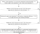
FIG. 1 shows a flowchart of a control method of Embodiment 1 of the present application; -
FIG. 2 shows a flowchart of a control method ofEmbodiment 2 of the present application; -
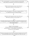
FIG. 3 shows a flowchart of a control method of Embodiment 3 of the present application; -
FIG. 4 shows a flowchart of a control method of Embodiment 4 of the present application; -
FIG. 5 shows a flowchart of a control method of Embodiment 5 of the present application; -
FIG. 6 shows a flowchart of a control method of Embodiment 6 of the present application; -
FIG. 7 shows a schematic structural diagram of an air source heat pump unit system of Embodiment 7 of the present application. - In the accompanying drawings, the same component is marked with the same reference numeral. The accompanying drawings fail to follow an actual scale.
- 10. Heat pump unit; 20. Water supply pipeline; 30. End heat exchanger; 40. Return water pipeline; 50. Water pump; 60. End valve.
- Explanation of the present application will be further provided with reference with accompanying drawings in the following.
- It may be noted that in the present application, an end refers to a room heated by an air source heat pump unit system, and a change in an actual demand at the end in the present application includes a change of current temperature of the room mentioned above.
- The present application provides a control method for an air source heat pump unit system, including:
controlling a supply water temperature of the air source heat pump unit system by monitoring a change in an actual demand at an end. - In the step mentioned above, by the monitoring the change in the actual demand at the end, an operating status of the air source heat pump unit system is adjusted, thereby reducing an actual supply water temperature of the air source heat pump unit system. Therefore, an operating energy consumption of the air source heat pump unit system is reduced, an operating efficiency of the system is improved, energy waste of the system is reduced, and a stable operation of the system is ensured. Furthermore, room comfort is improved, so as to provide a better experience to a user.
- As shown in
FIG. 1 , the present application provides a control method for an air source heat pump unit system. The air source heat pump unit system is used to adjust a temperature of a room, and the control method for the air source heat pump unit system control method includes the following steps. - Step 1: setting a target temperature T of a room and a temperature deviation threshold ΔT1;
- Step 2: setting a supply water temperature T1 and a return water temperature T2 of the air source heat pump unit system (
Step 2 and Step 1 are combined together inFIG. 1 , and there is no sequential relationship between the two steps); - Step 3: determining whether a current temperature deviation value of the room of the air source heat bump unit system is higher than the temperature deviation threshold ΔT1 of the air source heat bump unit system. The current temperature deviation value of the room is a difference between a current temperature of the room and the target temperature of the room.
- When the current temperature deviation value of the room of the air source heat bump unit system is higher than the temperature deviation threshold ΔT1 of the air source heat bump unit system (if yes), the supply water temperature T1 is reduced while a temperature difference ΔT of supply and return water is ensured remaining unchanged.
- When the current temperature deviation value of the room of the air source heat bump unit system fails to be higher than the temperature deviation threshold ΔT1 of the air source heat bump unit system (if no), the step of setting the supply water temperature T1 and the return water temperature T2 of the air source heat pump unit system is returned.
- The temperature difference ΔT of supply and return water of the air source heat pump unit system is a difference between the supply water temperature T1 and the return water temperature T2, and the supply water temperature T1 is higher than the return water temperature T2 in the air source heat pump unit system.
- Base on the steps mentioned above, by adjusting an operating status of the air source heat pump unit system, an actual supply water temperature of the air source heat pump unit system is reduced, and the temperature difference of supply and return water of the air source heat pump unit system remains unchanged. Therefore, an operating energy consumption of the air source heat pump unit system is reduced, an operating efficiency of the system is improved, energy waste of the system is reduced, and a stable operation of the system is ensured. Furthermore, room comfort is improved, so as to provide a better experience to a user.
- A difference between
Embodiment 2 and Embodiment 1 will be described below. - Specifically, as shown in
FIG. 2 , in an embodiment, the control method further includes the following step. - Step 4: determining whether the current temperature deviation value of the room of the air source heat bump unit system is higher than the temperature deviation threshold ΔT1 of the air source heat bump unit system.
- When the current temperature deviation value of the room of the air source heat bump unit system is higher than the temperature deviation threshold ΔT1 of the air source heat bump unit system (if yes), the supply water temperature T1 of the air source heat bump unit system is continually reduced, the return water temperature T2 of the air source heat bump unit system is synchronously reduced, and the temperature difference ΔT of supply and return water is ensured remaining unchanged.
- When the current temperature deviation value of the room of the air source heat bump unit system fails to be higher than the temperature deviation threshold ΔT1 of the air source heat pump unit system (if not), the step of reducing the supply water temperature T1 of the air source heat pump unit system while ensuring the temperature difference ΔT of supply and return water of the air source heat pump unit system remaining unchanged is returned.
- Base on the steps mentioned above, by adjusting an operating status of the air source heat pump unit system, an actual supply water temperature and an actual return water temperature of the air source heat pump unit system are reduced, and the temperature difference of supply and return water of the air source heat pump unit system remains unchanged. Therefore, an operating energy consumption of the air source heat pump unit system is reduced, an operating efficiency of the system is improved, energy waste of the system is reduced, and a stable operation of the system is ensured. Furthermore, room comfort is improved, so as to provide a better experience to a user.
- The other steps in
Embodiment 2 are the same as those in Embodiment 1, and will not be repeated here. - A difference between Embodiment 3 and
Embodiment 2 will be described below. - Specifically, as shown in
FIG. 3 , in an embodiment, the control method further includes the following step. - Step 5: determining whether the current temperature deviation value of the room of the air source heat bump unit system is higher than the temperature deviation threshold ΔT1 of the air source heat bump unit system when the supply water temperature T1 of the air source heat bump unit system is lower than a lower limit temperature.
- When the current temperature deviation value of the room of the air source heat bump unit system is higher than the temperature deviation threshold ΔT1 of the air source heat bump unit system (if yes), an opening degree of an end valve is adjusted, and a rotary speed of a water pump is synchronously adjusted through interlock to reduce a circulating water volume of the system.
- When the current temperature deviation value of the room of the air source heat bump unit system fails to be higher than the temperature deviation threshold ΔT1 of the air source heat pump unit system (if not), the step of continually reducing the supply water temperature T1, synchronously reducing the return water temperature T2, and ensuring the temperature difference ΔT of supply and return water remaining unchanged is returned.
- Base on the steps mentioned above, by adjusting an operating status of the air source heat pump unit system, the circulating water volume of the system is reduced. Therefor, an operating energy consumption of the air source heat pump unit system is reduced, an operating efficiency of the system is improved, energy waste of the system is reduced, and a stable operation of the system is ensured. Furthermore, room comfort is improved, so as to provide a better experience to a user.
- It may be noted that the rotary speed of the water pump is synchronously adjusted through interlock in the present application refers to that the rotary speed of the water pump only can be adjusted when the opening degree of the end valve starts to be adjusted.
- The other steps in Embodiment 3 are the same as those in
Embodiment 2, and will not be repeated here. - A difference between Embodiment 4 and Embodiment 3 will be described below.
- Specifically, as shown in
FIG. 4 , in an embodiment, the control method further includes the following step. - Step 6: determining whether the current temperature deviation value of the room of the air source heat bump unit system is higher than the temperature deviation threshold ΔT1 of the air source heat bump unit system when the rotary speed of the water pump is determined to reach a lower limit value.
- When the current temperature deviation value of the room of the air source heat bump unit system is higher than the temperature deviation threshold ΔT1 of the air source heat bump unit system (if yes), a unit is turned off (that is, a heat pump unit is turned off), and the water pump is operated at a low frequency to maintain water circulation of the system.
- When the current temperature deviation value of the room of the air source heat bump unit system fails to be higher than the set temperature deviation threshold ΔT1 of the air source heat pump unit system (if not), the step of adjusting the opening degree of the end valve and synchronously adjusting the rotary speed of the water pump through interlock to reduce the circulating water volume of the system is returned.
- Base on the steps mentioned above, by turning off the unit and reducing the rotary speed of the water pump, an operating energy consumption of the air source heat pump unit system is reduced, an operating efficiency of the system is improved, energy waste of the system is reduced, and a stable operation of the system is ensured. Furthermore, room comfort is improved, so as to provide a better experience to a user.
- The other steps in Embodiment 4 are the same as those in Embodiment 3, and will not be repeated here.
- Specifically, as shown in
FIG. 5 , in an embodiment, the control method further includes the following step. - Step 7: determining whether the temperature difference ΔT of supply and return water becomes smaller.
- When the temperature difference ΔT of supply and return water becomes smaller (if yes), the water pump of the air source heat pump unit system is turned off.
- When the temperature difference ΔT of supply and return water doesn't become smaller (if not), the step of turning off the unit and operating the water pump at the low frequency to maintain the circulating water volume of the system is returned.
- The other steps in Embodiment 5 are the same as those in Embodiment 4, and will not be repeated here.
- A difference between Embodiment 6 and Embodiment 5 will be described below.
- Specifically, as shown in
FIG. 6 , in an embodiment, the control method further includes the following step. - Step 8, determining whether the current temperature deviation value of the room of the air source heat bump unit system is lower than the temperature deviation threshold ΔT1 of the air source heat bump unit system.
- When the current temperature deviation value of the room of the air source heat bump unit system is lower than the temperature deviation threshold ΔT1 of the air source heat pump system (if yes), the unit of the air source heat pump unit system and the water pump of the air source heat pump unit system are restarted.
- When the current temperature deviation value of the room of the air source heat bump unit system is not lower than the temperature deviation threshold ΔT1 of the air source heat pump system (if no), the step of turning off the water pump of the air source heat pump unit system is returned.
- The other steps in Embodiment 6 are the same as those in Embodiment 5, and will not be repeated here.
- As shown in
FIG. 7 , the present application further provides an air source heat pump unit system. The air source heat pump unit system adopts the control method mentioned above to adjust a temperature of a room. The air source heat pump unit system includes aheat pump unit 10, awater supply pipeline 20, anend heat exchanger 30, areturn water pipeline 40, awater pump 50, and anend valve 60. One end of thewater supply pipeline 20 is connected to an output of theheat pump unit 10; an input of theend heat exchanger 30 is connected to the other end of thewater supply pipeline 20; one end of thereturn water pipeline 40 is connected to the input of theheat pump unit 10; and the other end is connected to an output of theend heat exchanger 30. Thewater pump 50 is disposed on thereturn water pipeline 40, and theend valve 60 is disposed on thesupply water pipeline 20. Thewater pump 50 cooperates with theend valve 60 to adjust a circulating water volume of the air source heat pump unit system. By adjusting a supply water temperature, a return water temperature, and the circulating water volume of the air source heat pump unit system, an operation efficiency of the air source heat pump unit system is improved. - In the configuration mentioned above, by monitoring a change of temperature in the room, a change of room load is predicted, and then the supply water temperature, the return water temperature of the system and the circulating water volume of the system are timely adjusted. Therefore, the operating efficiency of the system is improved, energy waste of the system is reduced, and a stable operation of the system is ensured. Furthermore, room comfort is improved, so as to provide a better experience to a user.
- It may be noted that the
heat pump unit 10 and thewater pump 50 in the present application adopt variable frequency control. By monitoring the change of temperature in the room, the change of the room load is predicted, and then the supply water temperature of the system and the operating status of the water pump are timely adjusted. That is, the water temperature of the system is adjusted based on the change of the room load. Therefore, the operating efficiency of the system is improved, the energy waste of the system is reduced, and the stable operation of the system is ensured. Furthermore, the room comfort is improved. - It may be noted that during heating of the air source heat pump unit system in winter, output capacity of the unit may match the change of the room load at the end to avoid waste. For a conventional frequency conversion system, a unit is controlled by setting the supply water temperature. When temperature of the room reaches a set value, the unit may start and stop frequently. In the present application, the supply water temperature of the unit is controlled by monitoring a change in an actual demand at the end. Therefore, the problem in an application of the conventional frequency conversion system may be solved by adjusting the supply water temperature of the unit. For example, when the room load is reduced, by reducing the supply water temperature of the unit, the frequent start and stop phenomena caused by the change of the room load may be relieved. Therefore, system stability and comprehensive energy efficiency is improved. Meanwhile, when the room load continues to decrease, the circulating water volume of the system may be further reduced, thereby reducing an energy consumption of the water pump and reducing an energy consumption of the system.
- In the following a more specific embodiment of the present application will be described.
- The present application provides an air source heat pump unit system, including: a variable frequency air source heat pump unit, a variable frequency delivery water pump, an
end heat exchanger 30, a circulating pipeline (including areturn water pipeline 40 and a water supply pipeline 20), a temperature sensor, and an electric control valve (i.e., an end valve 60), etc. - During a heating process in winter, the variable frequency air source heat pump unit is used to absorb heat from air, increase the heat by driving the unit, and provide hot water at a suitable temperature to the
end heat exchanger 30 for room heating. - Unit capacity adjustment process will be described below. A heating temperature of a room is set to a suitable target temperature value T (that is, temperature of the room is adjusted). At this time, a supply water temperature of the variable frequency air source heat pump unit is set to T1, and a return water temperature after room heat exchange changes to T2. A temperature difference of supply and return water of the variable frequency air source heat pump unit is ΔT (T1-T2). The delivery water pump is utilized to circulate hot water in a pipeline network. Due to correlation between an indoor heat load and various factors such as outdoor environment, personnel air conditioning usage habits, and a change in fresh air volume, when temperature of the outdoor environment changes, a room load will also change accordingly. When it is detected that the temperature of the room is higher than a temperature deviation threshold ΔT1, and maintains for a certain time period t1, at this time, it is manifested as an increase in the return water temperature of the pipeline network. The variable frequency air source heat pump unit detects the return water temperature of the unit increases and maintains for a certain time period t1. At this time, by adjusting an operating status of the unit, an actual supply water temperature of the unit is reduced, and the temperature difference ΔT of supply and return water remains unchanged to reduce an operating energy consumption of the unit. If the temperature of the room is still higher than the temperature deviation threshold ΔT1, the supply water temperature of the unit may still be reduced continuously. At this time, an adjustment method of the unit is to control a rotary speed of a compressor through frequency conversion, and synchronously reduce the return water temperature of the unit while maintaining the temperature difference ΔT of supply and return water unchanged. When the supply water temperature of the unit has reached a preset lower limit temperature and it is detected that the temperature of the room is still higher than the temperature deviation threshold ΔT1 and the return water temperature of the unit is higher than a preset lower limit temperature, at this time, by adjusting an opening degree of a valve (i.e., an opening degree of an electric control valve) of the
end heat exchanger 30 of the room, a flow rate of the hot water at the end heat exchang is reduced, and a rotary speed of the variable frequency delivery water pump is synchronously interlocked to reduce a circulating water volume of the system and an energy consumption of the variable frequency delivery water pump. When the rotary speed of the variable frequency delivery water pump reaches a lower limit value (that is, a rotary speed corresponds to a significant decrease of efficiency of the water pump), and maintains for a certain time period t3, and the temperature of the room is still higher than the temperature deviation threshold ΔT1, at this time, the variable frequency air source heat pump unit is turned off, while the variable frequency delivery water pump continues to operate at a lowest allowable frequency to maintain water circulation of the system. When only the variable frequency delivery water pump is operated, and the temperature difference ΔT of supply and return water is detected to gradually decrease and maintain for a certain time period t4, then the variable frequency delivery water pump is turned off. When a main engine of the variable frequency air source heat pump unit and the variable frequency delivery water pump are turned off, and the temperature of the room is detected to be lower than the temperature deviation threshold ΔT1 and maintain for a certain time period t5, the variable frequency delivery water pump and the variable frequency air source heat pump unit are restarted for heating. Meanwhile, during the adjustment process of the system, if the temperature of the room drops and falls below a lower limit of a preset room temperature deviation value, the unit frequency reduction control will be stopped, and an operating frequency of the unit will be appropriately increased to increase the temperature of the room. This loop control achieves an improvement in system efficiency. - It may be noted that the control method may improve an efficiency of the variable frequency air source heat pump unit, reduce frequent start and stop, reduce usage faults, and prolong a service life of the compressor by reducing the temperature of the supply water of hot water preferentially. Meanwhile, a frequency of fluctuation of the temperature of the room may be reduced, room comfort at the end may be maintained, and the waste of room heat may be reduced. In addition, by adjusting a flow rate of the system through the variable frequency delivery water pump, the energy consumption of the water pump may be reduced, and a comprehensive operating efficiency of the system may be improved.
- The air source heat pump unit system and the control method therefor in the present application have the following advantages.
- 1. The comprehensive energy efficiency of the system is improved and an operating cost is reduced.
- 2. Operating efficiency of the unit is improved and power consumption of the unit is reduced.
- 3. Energy consumption of delivery equipment is reduced and the power consumption of the system is reduced.
- 4. Load adjustment range of the system is enlarged and ineffective energy waste is reduced.
- In an embodiment, the present application further provides a computer device, including a memory and a processor, the memory being configured to store a computer program. The processor is configured to execute the computer program to implement the steps of any one of the control methods for the air source heat pump unit system mentioned above.
- In an embodiment, the present application further provides a non-transitory computer-readable storage medium storing a computer program. The computer program is executed by a processor to implement the steps of any one of the control methods for the air source heat pump unit system mentioned above.
- Those skilled in the art can understand and implement all or part of the processes in the embodiments mentioned above, which may be implemented by instructing a relevant hardware through computer programs. The computer program may be stored in a non-transitory computer-readable storage medium, and when the computer programs are executed, processes in the embodiments of the method mentioned above may be included. Therein, any reference to memory, storage, database, or other media used in the embodiments provided in the present application may include at least one of non-volatile and volatile memory. The non-volatile memory may include a Read-Only Memory (ROM), a magnetic tape, a floppy disk, a flash memory, or an optical memory. The volatile memory may include a Random Access Memory (RAM) or an external cache memory. As an explanation rather than limitation, RAM may include various forms, such as a Static Random Access Memory (SRAM) or a Dynamic Random Access Memory (DRAM).
- In the description of this application, it should be understood that the terms "up", "down", "bottom", "top", "front", "back", "inside", "outside", "left", "right", etc. indicate that the orientation or position relationship based on the orientation or position relationship shown in the accompanying drawings is only for the convenience of describing the present application and simplifying the description, and not to indicate or imply that the device or component referred to must have a specific orientation, or be constructed and operated in a specific orientation, which cannot be understood as a limitation on this application accordingly.
- Although specific embodiments have been referred to in the specification to describe the present application, it should be understood that these embodiments are only examples of the principles and applications of the present application. Therefore, it should be understood that many modifications may be made to exemplary embodiments, and other arrangements may be designed as long as they do not deviate from the spirit and scope of the present application as defined by the attached claims. It should be understood that different dependent claims and the features described in the specification can be combined in a way different from the original claims. It can also be understood that the features described in a single embodiment may be used in other embodiments.
Claims (12)
- A control method for an air source heat pump unit system, characterized by comprising:
controlling a supply water temperature of the air source heat pump unit system by monitoring a change in an actual demand at an end. - The control method for the air source heat pump unit system according to claim 1, characterized by comprising:setting a target temperature (T) of a room and a temperature deviation threshold (ΔT1);setting a supply water temperature (T1) and a return water temperature (T2) of the air source heat pump unit system;determining whether a current temperature deviation value of the room is higher than the temperature deviation threshold (ΔT1), wherein the current temperature deviation value of the room is a difference between a current temperature of the room and the target temperature (T) of the room; andreducing the supply water temperature (T1) while ensuring a temperature difference (ΔT) of supply and return water remaining unchanged when the current temperature deviation value of the room is higher than the temperature deviation threshold (ΔT1);wherein the temperature difference (ΔT) of supply and return water is a difference between the supply water temperature (T1) and the return water temperature (T2), and the supply water temperature (T1) is higher than the return water temperature (T2).
- The control method for the air source heat pump unit system according to claim 2, characterized by further comprising:determining whether the current temperature deviation value of the room is higher than the temperature deviation threshold (ΔT1); andcontinually reducing the supply water temperature (T1), synchronously reducing the return water temperature (T2), and ensuring the temperature difference (ΔT) of supply and return water remaining unchanged when the current temperature deviation value of the room is higher than the temperature deviation threshold (ΔT1).
- The control method for the air source heat pump unit system according to claim 3, characterized by:
returning to the step of reducing the supply water temperature (T1) while ensuring the temperature difference (ΔT) of supply and return water remaining unchanged when the current temperature deviation value of the room fails to be higher than the temperature deviation threshold (ΔT1). - The control method for the air source heat pump unit system according to claim 3, characterized by further comprising:determining whether the current temperature deviation value of the room is higher than the temperature deviation threshold (ΔT1) when the supply water temperature (T1) is lower than a lower limit temperature; andadjusting an opening degree of an end valve and synchronously adjusting a rotary speed of a water pump to reduce a circulating water volume of the system when the current temperature deviation value of the room is higher than the temperature deviation threshold (ΔT1).
- The control method for the air source heat pump unit system according to claim 5, characterized by further comprising:determining whether the current temperature deviation value of the room is higher than the temperature deviation threshold (ATI) when the rotary speed of the water pump is determined to reach a lower limit value; andturning off the unit, and operating the water pump at a low frequency to maintain water circulation of the system, when the the current temperature deviation value of the room is higher than the temperature deviation threshold (ΔT1).
- The control method of the air source heat pump unit system according to claim 6, characterized by:
returning to the step of adjusting the opening degree of the end valve and synchronously adjusting the rotary speed of the water pump to reduce the circulating water volume of the system when the current temperature deviation value of the room fails to be higher than the temperature deviation threshold (ΔT1). - The control method of the air source heat pump unit system according to claim 6, characterized by further comprising:determining whether the temperature difference (ΔT) of supply and return water becomes smaller; andturning off the water pump when the temperature difference (ΔT) of supply and return water becomes smaller.
- The control method of the air source heat pump unit system according to claim 8, characterized by further comprising:determining whether the current temperature deviation value of the room is lower than the temperature deviation threshold (ΔT1); andrestarting the unit and the water pump when the current temperature deviation value of the room is lower than the temperature deviation threshold (ΔT1).
- An air source heat pump unit system, characterized by being configured to adjust a temperature of a room, comprising:a heat pump unit;a water supply pipeline, wherein one end of the water supply pipeline is connected to an output of the heat pump unit;an end heat exchanger, wherein an input of the end heat exchanger is connected to the other end of the water supply pipeline;a return water pipeline, wherein one end of the return water pipeline is connected to an input of the heat pump unit, and the other end of the return water pipeline is connected to an output of the end heat exchanger;a water pump, wherein the water pump is disposed on the water supply pipeline or the return water pipeline;an end valve, wherein the end valve is disposed on the water supply pipeline; anda controller, wherein the controller is configured to cooperate with the water pump and the end valve to control the air source heat pump unit system by implementing the steps of the method according to any one of claims 1 to 8.
- A computer device, comprising:a memory and a processor, the memory being configured to store a computer program; andcharacterized in that, the processor is configured to execute the computer program to implement the steps of the method according to any one of claims 1 to 8.
- A non-transitory computer-readable storage medium, storing a computer program, characterized by implementing the steps of the method according to any one of claims 1 to 8 when the computer program is executed.
Applications Claiming Priority (2)
| Application Number | Priority Date | Filing Date | Title |
|---|---|---|---|
| CN202111276386.5A CN114110933B (en) | 2021-10-29 | 2021-10-29 | Control method of air source heat pump unit system and air source heat pump unit system |
| PCT/CN2022/108251 WO2023071331A1 (en) | 2021-10-29 | 2022-07-27 | Control method for air source heat pump unit system and air source heat pump unit system |
Publications (3)
| Publication Number | Publication Date |
|---|---|
| EP4425065A1 true EP4425065A1 (en) | 2024-09-04 |
| EP4425065A4 EP4425065A4 (en) | 2025-03-12 |
| EP4425065B1 EP4425065B1 (en) | 2026-03-04 |
Family
ID=80379670
Family Applications (1)
| Application Number | Title | Priority Date | Filing Date |
|---|---|---|---|
| EP22885232.3A Active EP4425065B1 (en) | 2021-10-29 | 2022-07-27 | Control method for air source heat pump unit system and air source heat pump unit system |
Country Status (3)
| Country | Link |
|---|---|
| EP (1) | EP4425065B1 (en) |
| CN (1) | CN114110933B (en) |
| WO (1) | WO2023071331A1 (en) |
Families Citing this family (10)
| Publication number | Priority date | Publication date | Assignee | Title |
|---|---|---|---|---|
| CN114110933B (en) * | 2021-10-29 | 2023-08-01 | 珠海格力电器股份有限公司 | Control method of air source heat pump unit system and air source heat pump unit system |
| CN115264555B (en) * | 2022-07-15 | 2024-05-28 | 珠海格力电器股份有限公司 | Heating control method and device and heating system |
| CN115597210B (en) * | 2022-10-17 | 2025-01-24 | 青岛海信日立空调系统有限公司 | An air conditioning system |
| CN115682468B (en) * | 2022-11-07 | 2023-04-14 | 鼎恒(烟台)科技发展有限公司 | Air source heat pump set intelligence operation and maintenance management and control system based on data analysis |
| CN115789925B (en) * | 2022-12-30 | 2026-01-13 | 辽宁省鑫源绿色发展集团有限公司 | Energy-saving temperature control method of air source heat pump, temperature control method capable of being connected with network, temperature controller and temperature control system |
| CN117029091A (en) * | 2023-08-04 | 2023-11-10 | 广东Tcl智能暖通设备有限公司 | A control method and device for improving the heat exchange efficiency of an air source heat pump heating unit, air source heat pump |
| CN117329584B (en) * | 2023-11-20 | 2026-05-26 | 青岛北冰洋冷暖能源科技有限公司 | Centralized control method for variable-flow multi-module variable-frequency air source heat pump energy station |
| CN117515634B (en) * | 2023-12-15 | 2026-07-17 | 珠海格力电器股份有限公司 | Heat pump system control method and heat pump system |
| CN117803976A (en) * | 2023-12-29 | 2024-04-02 | 广东纽恩泰新能源科技股份有限公司 | Air energy heat pump control method and system |
| CN119468444B (en) * | 2024-11-12 | 2025-11-18 | 广东芬尼能源技术有限公司 | Air source heat pump system control methods, equipment, devices and media |
Family Cites Families (19)
| Publication number | Priority date | Publication date | Assignee | Title |
|---|---|---|---|---|
| JP3583536B2 (en) * | 1995-12-14 | 2004-11-04 | 高砂熱学工業株式会社 | Air conditioner, air conditioning system and control method thereof |
| JP4710571B2 (en) * | 2005-11-30 | 2011-06-29 | パナソニック株式会社 | Air conditioner |
| JP4842654B2 (en) * | 2006-02-10 | 2011-12-21 | 株式会社石本建築事務所 | Control method for air conditioning system for radiant panel |
| JP4594276B2 (en) * | 2006-05-26 | 2010-12-08 | 東洋熱工業株式会社 | Cold / hot water control method for cold / hot heat source machine and air conditioning system used therefor |
| CN101256020B (en) * | 2008-04-16 | 2010-07-21 | 谭文胜 | Method and apparatus for controlling central air-conditioning end supply backwater temperature difference |
| EP3306204B1 (en) * | 2015-06-03 | 2021-07-07 | Mitsubishi Electric Corporation | Hot-water heating system, control device, and control method |
| CN105222219B (en) * | 2015-09-16 | 2017-08-29 | 江苏天舒电器有限公司 | A kind of source pump alternating temperature heating temperature control method of water and its control device |
| CN106989477B (en) * | 2016-11-11 | 2019-06-04 | 深圳达实智能股份有限公司 | Control method, control device and the central air conditioner system of refrigerating water pump after cold is shut down |
| CN107062515A (en) * | 2016-11-30 | 2017-08-18 | 青岛海尔空调电子有限公司 | A kind of water chilling unit control method |
| CN106766222B (en) * | 2016-12-26 | 2019-08-16 | 珠海格力电器股份有限公司 | Water supply temperature adjusting method and device of heat pump water heater |
| EP3364116B1 (en) * | 2017-02-16 | 2020-06-03 | Mitsubishi Electric R&D Centre Europe B.V. | Method for controlling a heat pump system and heat pump system |
| CN108662735B (en) * | 2018-05-29 | 2020-09-11 | 广州大学 | Energy-saving optimization control system and method for terminal equipment of central air-conditioning system |
| CN109237713B (en) * | 2018-09-25 | 2020-06-09 | 珠海格力电器股份有限公司 | Water multi-connected unit operation control method and device, medium and water multi-connected air conditioning system |
| CN109556241B (en) * | 2018-09-29 | 2021-05-25 | 青岛海尔空调电子有限公司 | Water system air conditioner control method |
| CN110486939A (en) * | 2019-07-29 | 2019-11-22 | 四季沐歌科技集团有限公司 | A kind of air energy constant temperature and pressure hot-water heating system and its control method |
| CN112665121B (en) * | 2020-12-10 | 2022-02-08 | 珠海格力电器股份有限公司 | Control method and device for air conditioner chilled water pump, controller and air conditioning system |
| CN112833487A (en) * | 2021-01-25 | 2021-05-25 | 长江勘测规划设计研究有限责任公司 | A large temperature difference air conditioning water transmission and distribution system based on a mixing pump and its control method |
| CN114001442A (en) * | 2021-10-18 | 2022-02-01 | 珠海格力电器股份有限公司 | Control method and device of air source heat pump unit and electronic equipment |
| CN114110933B (en) * | 2021-10-29 | 2023-08-01 | 珠海格力电器股份有限公司 | Control method of air source heat pump unit system and air source heat pump unit system |
-
2021
- 2021-10-29 CN CN202111276386.5A patent/CN114110933B/en active Active
-
2022
- 2022-07-27 WO PCT/CN2022/108251 patent/WO2023071331A1/en not_active Ceased
- 2022-07-27 EP EP22885232.3A patent/EP4425065B1/en active Active
Also Published As
| Publication number | Publication date |
|---|---|
| EP4425065B1 (en) | 2026-03-04 |
| CN114110933B (en) | 2023-08-01 |
| CN114110933A (en) | 2022-03-01 |
| EP4425065A4 (en) | 2025-03-12 |
| WO2023071331A1 (en) | 2023-05-04 |
Similar Documents
| Publication | Publication Date | Title |
|---|---|---|
| EP4425065B1 (en) | Control method for air source heat pump unit system and air source heat pump unit system | |
| CN113432348B (en) | Refrigerant circulation quantity adjusting device and method and air conditioning system | |
| CN202613835U (en) | Simultaneous cold and heat supply energy-saving system | |
| CN111207481A (en) | Water multi-connected system compressor frequency-up-down control method, storage medium and air conditioner | |
| CN112594904A (en) | Energy-saving optimization control system of refrigeration station | |
| CN108019890B (en) | Air conditioner energy efficiency control method and device and air conditioner system | |
| CN110567048B (en) | Control method and device for electronic expansion valve in multi-split air conditioning operation | |
| CN109945366B (en) | Water multi-connected unit control method, air conditioning water machine system and control method thereof | |
| CN116007144B (en) | Air conditioner control method and device, air conditioner and storage medium | |
| JP2007315695A (en) | Cold / hot water control method for cold / hot heat source machine and air conditioning system used therefor | |
| CN115540039A (en) | Multi-zone heating method, system and storage medium | |
| CN117515861B (en) | A method and control system for active optimization control of cooling towers based on energy efficiency of refrigeration room systems. | |
| CN101886834B (en) | Constant-energy constant-temperature constant-humidity air conditioning system | |
| CN110186225B (en) | System for improving supercooling degree of fluorine pump inlet and control method thereof | |
| WO2021135677A1 (en) | Control method for automatically switching operation mode of water chilling unit | |
| CN112665127B (en) | Ice storage air conditioning system and control method, device and controller thereof | |
| CN118935811B (en) | Operation control method and system for double-source double-effect heat pump unit | |
| CN211345737U (en) | Heat recovery side control system of heat recovery centrifugal unit | |
| CN115654704B (en) | Control method, control device and fresh air air conditioner for optimizing refrigeration effect of fresh air air conditioner | |
| CN116928801B (en) | Air conditioning control methods, devices and air conditioning units | |
| CN115013952B (en) | A control method and device for air conditioning system | |
| CN201344588Y (en) | Heat pump hot water unit capable of reliably supplying water | |
| CN115200169B (en) | Intelligent energy-saving control method for cogeneration energy | |
| US20250297756A1 (en) | Hvac system, control method for hvac system, and computer-readable storage medium | |
| CN119826449B (en) | Wine cabinet temperature control methods and wine cabinets |
Legal Events
| Date | Code | Title | Description |
|---|---|---|---|
| STAA | Information on the status of an ep patent application or granted ep patent |
Free format text: STATUS: THE INTERNATIONAL PUBLICATION HAS BEEN MADE |
|
| PUAI | Public reference made under article 153(3) epc to a published international application that has entered the european phase |
Free format text: ORIGINAL CODE: 0009012 |
|
| STAA | Information on the status of an ep patent application or granted ep patent |
Free format text: STATUS: REQUEST FOR EXAMINATION WAS MADE |
|
| 17P | Request for examination filed |
Effective date: 20240528 |
|
| AK | Designated contracting states |
Kind code of ref document: A1 Designated state(s): AL AT BE BG CH CY CZ DE DK EE ES FI FR GB GR HR HU IE IS IT LI LT LU LV MC MK MT NL NO PL PT RO RS SE SI SK SM TR |
|
| DAV | Request for validation of the european patent (deleted) | ||
| DAX | Request for extension of the european patent (deleted) | ||
| A4 | Supplementary search report drawn up and despatched |
Effective date: 20250210 |
|
| RIC1 | Information provided on ipc code assigned before grant |
Ipc: F24F 11/46 20180101ALI20250204BHEP Ipc: F24F 11/30 20180101ALI20250204BHEP Ipc: F24H 15/375 20220101ALI20250204BHEP Ipc: F24H 15/34 20220101ALI20250204BHEP Ipc: F24H 15/254 20220101ALI20250204BHEP Ipc: F24H 15/212 20220101ALI20250204BHEP Ipc: F24H 15/175 20220101ALI20250204BHEP Ipc: F24H 15/156 20220101ALI20250204BHEP Ipc: F24H 4/02 20220101ALI20250204BHEP Ipc: F24F 11/84 20180101ALI20250204BHEP Ipc: F24F 11/83 20180101ALI20250204BHEP Ipc: F24D 19/10 20060101ALI20250204BHEP Ipc: F24D 3/18 20060101ALI20250204BHEP Ipc: F24F 11/64 20180101AFI20250204BHEP |
|
| GRAP | Despatch of communication of intention to grant a patent |
Free format text: ORIGINAL CODE: EPIDOSNIGR1 |
|
| STAA | Information on the status of an ep patent application or granted ep patent |
Free format text: STATUS: GRANT OF PATENT IS INTENDED |
|
| RIC1 | Information provided on ipc code assigned before grant |
Ipc: F24F 11/64 20180101AFI20251017BHEP Ipc: F24D 3/18 20060101ALI20251017BHEP Ipc: F24D 19/10 20060101ALI20251017BHEP Ipc: F24F 11/83 20180101ALI20251017BHEP Ipc: F24F 11/84 20180101ALI20251017BHEP Ipc: F24H 4/02 20220101ALI20251017BHEP Ipc: F24H 15/156 20220101ALI20251017BHEP Ipc: F24H 15/175 20220101ALI20251017BHEP Ipc: F24H 15/212 20220101ALI20251017BHEP Ipc: F24H 15/254 20220101ALI20251017BHEP Ipc: F24H 15/34 20220101ALI20251017BHEP Ipc: F24H 15/375 20220101ALI20251017BHEP Ipc: F24F 11/30 20180101ALI20251017BHEP Ipc: F24F 11/46 20180101ALI20251017BHEP |
|
| INTG | Intention to grant announced |
Effective date: 20251030 |
|
| GRAS | Grant fee paid |
Free format text: ORIGINAL CODE: EPIDOSNIGR3 |
|
| GRAA | (expected) grant |
Free format text: ORIGINAL CODE: 0009210 |
|
| STAA | Information on the status of an ep patent application or granted ep patent |
Free format text: STATUS: THE PATENT HAS BEEN GRANTED |
|
| P01 | Opt-out of the competence of the unified patent court (upc) registered |
Free format text: CASE NUMBER: UPC_APP_0019501_4425065/2025 Effective date: 20251226 |
|
| AK | Designated contracting states |
Kind code of ref document: B1 Designated state(s): AL AT BE BG CH CY CZ DE DK EE ES FI FR GB GR HR HU IE IS IT LI LT LU LV MC MK MT NL NO PL PT RO RS SE SI SK SM TR |
|
| REG | Reference to a national code |
Ref country code: CH Ref legal event code: F10 Free format text: ST27 STATUS EVENT CODE: U-0-0-F10-F00 (AS PROVIDED BY THE NATIONAL OFFICE) Effective date: 20260304 Ref country code: GB Ref legal event code: FG4D |
|
| REG | Reference to a national code |
Ref country code: IE Ref legal event code: FG4D |
|
| REG | Reference to a national code |
Ref country code: DE Ref legal event code: R096 Ref document number: 602022031869 Country of ref document: DE |
|
| PG25 | Lapsed in a contracting state [announced via postgrant information from national office to epo] |
Ref country code: RS Free format text: LAPSE BECAUSE OF FAILURE TO SUBMIT A TRANSLATION OF THE DESCRIPTION OR TO PAY THE FEE WITHIN THE PRESCRIBED TIME-LIMIT Effective date: 20260604 |
|
| PG25 | Lapsed in a contracting state [announced via postgrant information from national office to epo] |
Ref country code: ES Free format text: LAPSE BECAUSE OF FAILURE TO SUBMIT A TRANSLATION OF THE DESCRIPTION OR TO PAY THE FEE WITHIN THE PRESCRIBED TIME-LIMIT Effective date: 20260304 |
|
| REG | Reference to a national code |
Ref country code: NL Ref legal event code: MP Effective date: 20260304 |
|
| PG25 | Lapsed in a contracting state [announced via postgrant information from national office to epo] |
Ref country code: PL Free format text: LAPSE BECAUSE OF FAILURE TO SUBMIT A TRANSLATION OF THE DESCRIPTION OR TO PAY THE FEE WITHIN THE PRESCRIBED TIME-LIMIT Effective date: 20260304 |
|
| PG25 | Lapsed in a contracting state [announced via postgrant information from national office to epo] |
Ref country code: GR Free format text: LAPSE BECAUSE OF FAILURE TO SUBMIT A TRANSLATION OF THE DESCRIPTION OR TO PAY THE FEE WITHIN THE PRESCRIBED TIME-LIMIT Effective date: 20260605 |
|
| REG | Reference to a national code |
Ref country code: LT Ref legal event code: MG9D |
|
| PG25 | Lapsed in a contracting state [announced via postgrant information from national office to epo] |
Ref country code: LT Free format text: LAPSE BECAUSE OF FAILURE TO SUBMIT A TRANSLATION OF THE DESCRIPTION OR TO PAY THE FEE WITHIN THE PRESCRIBED TIME-LIMIT Effective date: 20260304 |
|
| PG25 | Lapsed in a contracting state [announced via postgrant information from national office to epo] |
Ref country code: NO Free format text: LAPSE BECAUSE OF FAILURE TO SUBMIT A TRANSLATION OF THE DESCRIPTION OR TO PAY THE FEE WITHIN THE PRESCRIBED TIME-LIMIT Effective date: 20260604 |
|
| PG25 | Lapsed in a contracting state [announced via postgrant information from national office to epo] |
Ref country code: SE Free format text: LAPSE BECAUSE OF FAILURE TO SUBMIT A TRANSLATION OF THE DESCRIPTION OR TO PAY THE FEE WITHIN THE PRESCRIBED TIME-LIMIT Effective date: 20260304 Ref country code: FI Free format text: LAPSE BECAUSE OF FAILURE TO SUBMIT A TRANSLATION OF THE DESCRIPTION OR TO PAY THE FEE WITHIN THE PRESCRIBED TIME-LIMIT Effective date: 20260304 |
|
| PG25 | Lapsed in a contracting state [announced via postgrant information from national office to epo] |
Ref country code: HR Free format text: LAPSE BECAUSE OF FAILURE TO SUBMIT A TRANSLATION OF THE DESCRIPTION OR TO PAY THE FEE WITHIN THE PRESCRIBED TIME-LIMIT Effective date: 20260304 |
|
| PG25 | Lapsed in a contracting state [announced via postgrant information from national office to epo] |
Ref country code: LV Free format text: LAPSE BECAUSE OF FAILURE TO SUBMIT A TRANSLATION OF THE DESCRIPTION OR TO PAY THE FEE WITHIN THE PRESCRIBED TIME-LIMIT Effective date: 20260304 |
|
| PG25 | Lapsed in a contracting state [announced via postgrant information from national office to epo] |
Ref country code: BG Free format text: LAPSE BECAUSE OF FAILURE TO SUBMIT A TRANSLATION OF THE DESCRIPTION OR TO PAY THE FEE WITHIN THE PRESCRIBED TIME-LIMIT Effective date: 20260304 |