EP4425060A1 - Outdoor unit of refrigeration cycle device - Google Patents
Outdoor unit of refrigeration cycle device Download PDFInfo
- Publication number
- EP4425060A1 EP4425060A1 EP21962318.8A EP21962318A EP4425060A1 EP 4425060 A1 EP4425060 A1 EP 4425060A1 EP 21962318 A EP21962318 A EP 21962318A EP 4425060 A1 EP4425060 A1 EP 4425060A1
- Authority
- EP
- European Patent Office
- Prior art keywords
- blower
- outdoor unit
- housing
- refrigeration cycle
- impeller
- Prior art date
- Legal status (The legal status is an assumption and is not a legal conclusion. Google has not performed a legal analysis and makes no representation as to the accuracy of the status listed.)
- Withdrawn
Links
Images










Classifications
-
- F—MECHANICAL ENGINEERING; LIGHTING; HEATING; WEAPONS; BLASTING
- F24—HEATING; RANGES; VENTILATING
- F24F—AIR-CONDITIONING; AIR-HUMIDIFICATION; VENTILATION; USE OF AIR CURRENTS FOR SCREENING
- F24F1/00—Room units for air-conditioning, e.g. separate or self-contained units or units receiving primary air from a central station
- F24F1/06—Separate outdoor units, e.g. outdoor unit to be linked to a separate room comprising a compressor and a heat exchanger
- F24F1/38—Fan details of outdoor units, e.g. bell-mouth shaped inlets or fan mountings
-
- F—MECHANICAL ENGINEERING; LIGHTING; HEATING; WEAPONS; BLASTING
- F24—HEATING; RANGES; VENTILATING
- F24F—AIR-CONDITIONING; AIR-HUMIDIFICATION; VENTILATION; USE OF AIR CURRENTS FOR SCREENING
- F24F1/00—Room units for air-conditioning, e.g. separate or self-contained units or units receiving primary air from a central station
- F24F1/06—Separate outdoor units, e.g. outdoor unit to be linked to a separate room comprising a compressor and a heat exchanger
- F24F1/40—Vibration or noise prevention at outdoor units
-
- F—MECHANICAL ENGINEERING; LIGHTING; HEATING; WEAPONS; BLASTING
- F24—HEATING; RANGES; VENTILATING
- F24F—AIR-CONDITIONING; AIR-HUMIDIFICATION; VENTILATION; USE OF AIR CURRENTS FOR SCREENING
- F24F13/00—Details common to, or for air-conditioning, air-humidification, ventilation or use of air currents for screening
- F24F13/30—Arrangement or mounting of heat-exchangers
-
- F—MECHANICAL ENGINEERING; LIGHTING; HEATING; WEAPONS; BLASTING
- F24—HEATING; RANGES; VENTILATING
- F24F—AIR-CONDITIONING; AIR-HUMIDIFICATION; VENTILATION; USE OF AIR CURRENTS FOR SCREENING
- F24F1/00—Room units for air-conditioning, e.g. separate or self-contained units or units receiving primary air from a central station
- F24F1/0007—Indoor units, e.g. fan coil units
- F24F1/0018—Indoor units, e.g. fan coil units characterised by fans
- F24F1/0022—Centrifugal or radial fans
-
- F—MECHANICAL ENGINEERING; LIGHTING; HEATING; WEAPONS; BLASTING
- F24—HEATING; RANGES; VENTILATING
- F24F—AIR-CONDITIONING; AIR-HUMIDIFICATION; VENTILATION; USE OF AIR CURRENTS FOR SCREENING
- F24F1/00—Room units for air-conditioning, e.g. separate or self-contained units or units receiving primary air from a central station
- F24F1/0007—Indoor units, e.g. fan coil units
- F24F1/0018—Indoor units, e.g. fan coil units characterised by fans
- F24F1/0033—Indoor units, e.g. fan coil units characterised by fans having two or more fans
Definitions
- the present disclosure relates to an outdoor unit of refrigeration cycle apparatus.
- An outside unit of air conditioner in which an air heat exchanger and a blower are provided, has been known as using a centrifugal blower (sirocco fan) as the blower, and providing air inlets on at least a back side of a housing, while providing air outlets on any of a right side, a left side, or a top side of the housing, or on both the left and right sides of the housing (see, for example, PTL 1).
- a centrifugal blower sino fan
- the size of air outlets of the centrifugal blower tends to be comparatively small relative to the size of the housing of the outdoor unit, particularly, the size of the air heat exchanger. This results in a reduction in airflow volume compared to a conventional outdoor unit of the same size and having a propeller fan installed therein. It is thus difficult to obtain a sufficient airflow volume particularly when a static pressure external to the outdoor unit is high. In addition, the airflow volume is reduced, which makes it difficult to achieve sufficient pressure recovery. This leads to an increase in noise level and an increase in input.
- the present disclosure has been made to solve such problems. It is an object of the present disclosure to provide an outdoor unit of refrigeration cycle apparatus, in which even when a static pressure external to the outdoor unit is high, the outdoor unit can still obtain a large airflow volume, and can therefore achieve a low noise level and a low input, while preventing an increase in size of the outdoor unit.
- An outdoor unit of refrigeration cycle apparatus includes a housing in which a machine chamber and a blower chamber are formed, the blower chamber being partitioned from the machine chamber, the machine chamber housing a compressor inside, the blower chamber housing a heat exchanger and a blower inside, the blower being located on a secondary side of the heat exchanger, wherein the blower is a double inlet centrifugal blower including: an impeller having a plurality of blades arranged in a circumferential direction around a rotation axis, and a scroll casing having a discharge port and two bellmouths which serve as suction ports, the scroll casing housing the impeller inside, a plurality of the discharge ports are provided, the plurality of the discharge ports are located on an outlet placement surface, the outlet placement surface being a front or top surface of the housing, and a total width of the plurality of the discharge ports in a direction horizontal with the housing placed and parallel to the outlet placement surface is more than a width of the blower chamber in said direction.
- the blower is a
- the outdoor unit of refrigeration cycle apparatus achieves such effects that even when a static pressure external to the outdoor unit is high, the outdoor unit can still obtain a large airflow volume, and can therefore achieve a low noise level and a low input, while preventing an increase in size of the outdoor unit.
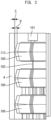
- Fig. 1 is a front view of an outdoor unit of refrigeration cycle apparatus with a front panel removed from the outdoor unit.
- Fig. 2 is a transparent top view illustrating relevant parts of the outdoor unit of refrigeration cycle apparatus.
- Fig. 3 is a transparent side view illustrating the relevant parts of the outdoor unit of refrigeration cycle apparatus.
- Figs. 4 and 5 are front views of the outdoor unit of refrigeration cycle apparatus.
- Fig. 6 is a plan view of an impeller of a blower included in the outdoor unit.
- Fig. 7 is a cross-sectional view of the blower included in the outdoor unit.
- Fig. 8 is a plan view of the impeller of the blower included in the outdoor unit.
- Fig. 9 is a cross-sectional view of the impeller of the blower included in the outdoor unit.
- Fig. 1 is a front view of an outdoor unit of refrigeration cycle apparatus with a front panel removed from the outdoor unit.
- Fig. 2 is a transparent top view illustrating relevant parts of the outdoor unit of
- Fig. 10 is a perspective view of the impeller of the blower included in the outdoor unit.
- Fig. 11 is a transparent top view of relevant parts, illustrating another example of the outdoor unit of refrigeration cycle apparatus.
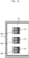
- Figs. 12 and 13 are top views illustrating still another example of the outdoor unit of refrigeration cycle apparatus.
- Fig. 14 is a top view illustrating still another example of the outdoor unit of refrigeration cycle apparatus with a top panel removed from the outdoor unit.
- Fig. 15 is a transparent front view of relevant parts, illustrating still another example of the outdoor unit of refrigeration cycle apparatus.
- a refrigeration cycle apparatus includes an indoor unit and an outdoor unit.
- a heat exchanger is provided in each of the indoor unit and the outdoor unit.
- the heat exchanger in the indoor unit, and the heat exchanger in the outdoor unit are connected by a refrigerant pipe provided to allow for circulation of refrigerant.
- the refrigeration cycle apparatus serves as a heat pump that causes refrigerant flowing through the refrigerant pipe to circulate between the heat exchanger in the indoor unit and the heat exchanger in the outdoor unit, thereby to transfer heat between the heat exchanger in the indoor unit and the heat exchanger in the outdoor unit.
- the outdoor unit of refrigeration cycle apparatus includes a housing 1.
- the housing 1 has, for example, a cuboid outer shape. That is, in the illustrated configuration, the housing 1 has a front surface, a back surface, a top surface, a bottom surface, and opposite left and right lateral surfaces.
- a machine chamber 2 and a blower chamber 3 are formed in the housing 1.
- the machine chamber 2 is located on one of the left and right sides of the housing 1.
- the blower chamber 3 is located on the other of the left and right sides of the housing 1.
- the machine chamber 2 and the blower chamber 3 are partitioned from each other.
- the machine chamber 2 houses a compressor, an electrical component box, and the like (not illustrated) inside.
- the blower chamber 3 houses a heat exchanger 4 and blowers 100 inside.
- outdoor-unit air inlets 5 are formed on the lateral surface and back surface of a portion of the housing 1 where the blower chamber 3 is located.
- a front panel 10 is provided on the front surface of a portion of the housing 1 where the blower chamber 3 is located.
- outdoor-unit air outlets 11 are formed on the front panel 10.
- the interior of the blower chamber 3 serves as an air passage extending from the outdoor-unit air inlets 5 to the outdoor-unit air outlets 11.
- the outdoor-unit air outlets 11 may be provided with grid-like grilles 12. In this case, the grilles 12 may be attached to the front panel 10, or may be provided integrally with the front panel 10.
- the heat exchanger 4 is located in an L-shape in top view, extending from the lateral surface to the back surface of the housing 1 on which the outdoor-unit air inlets 5 are provided.
- the blowers 100 are located downstream of the heat exchanger 4 in the air passage in the blower chamber 3. In other words, the blowers 100 are located on the secondary side of the heat exchanger 4.
- blower 100 As illustrated in Figs. 1 , and 3 to 5 , three blowers 100 are provided in the blower chamber 3 in a configuration example described here. In this configuration example, the three blowers 100 are arranged one above the other in an up-down direction. Each of the blowers 100 is a so-called double inlet centrifugal blower.
- the blower 100 includes an impeller 200, a scroll casing 110, a motor 101, and a shaft 102.
- the impeller 200 is a centrifugal fan configured to generate airflow in the blower 100. As illustrated in Fig. 2 and other drawings, the impeller 200 is housed inside the scroll casing 110. The impeller 200 is rotatable about a rotation axis inside the scroll casing 110. As illustrated in Fig. 6 , the impeller 200 has a plurality of blades 210. The plurality of blades 210 of the impeller 200 are arranged in a circumferential direction around the rotation axis of the impeller 200.
- the scroll casing 110 regulates a flow of air blown out from the impeller 200.
- the scroll casing 110 has two side walls and a peripheral wall.
- the side walls of the scroll casing 110 are provided on opposite sides of the impeller 200 in a direction along the rotation axis of the impeller 200.
- the peripheral wall of the scroll casing 110 is provided so as to surround the impeller 200 from the radially outer side of the impeller 200.
- the two side walls are located opposite to each other through the peripheral wall.
- two bellmouths 111 are formed on the scroll casing 110.
- the two bellmouths 111 on the scroll casing 110 serve as suction ports for the blower 100.
- the bellmouths 111 are provided respectively on the two side walls of the scroll casing 110.
- the suction ports formed in the bellmouths 111 have a circular shape centered at the rotation axis of the impeller 200. Note that the suction ports are not limited to having a circular shape, but may have other shapes such as an elliptical shape.
- the bellmouth 111 regulates a flow of gas to be suctioned into the impeller 200 and causes the regulated flow of gas to flow into the suction port of the impeller 200.
- the bellmouth 111 is formed in such a manner that its opening diameter gradually decreases from the outer part of the scroll casing 110 toward the inner part thereof. This allows air in the vicinity of the suction port to flow smoothly along the bellmouth 111 and flow efficiently into the impeller 200 from the suction port.
- the discharge port 112 is an opening through which airflow generated in the scroll casing 110 by the impeller 200 is discharged.
- the opening of the discharge port 112 has, for example, a rectangular shape. However, the opening of the discharge port 112 is not limited to having a rectangular shape.
- the plane of the opening of the discharge port 112 is positioned parallel to the rotation axis of the impeller 200.
- the peripheral wall of the scroll casing 110 guides the airflow generated by the impeller 200 along its curved wall surface to the discharge port 112.
- the peripheral wall is provided between the side walls opposite to each other.
- the peripheral wall is located parallel to the direction along the rotation axis of the impeller 200.
- the peripheral wall may be inclined relative to the direction along the rotation axis of the impeller 200, and is not limited to the configuration in which the peripheral wall is located parallel to the direction along the rotation axis.
- the peripheral wall of the scroll casing 110 is formed into a curved surface having an involute shape when viewed from a direction parallel to the rotation axis of the impeller 200.
- the involute shape is formed based on, for example, a logarithmic spiral, an Archimedean spiral, or an involute curve. Due to this shape, the air delivered from the impeller 200 smoothly flows through the gap between the impeller 200 and the peripheral wall in the direction toward the discharge port 112. This allows the static pressure of air in the scroll casing 110 to efficiently increase more toward the discharge port 112.
- the "rotation axis of the impeller 200" may also be referred to as “rotation axis of the blower 100.”
- the blower 100 having the configuration as described above is a double inlet centrifugal blower configured to suction air from opposite end sides of the rotation axis of the blower 100 and to blow out the air in a direction perpendicular to the rotation axis of the blower 100.
- the motor 101 and the shaft 102 are shared between the blowers 100. That is, in the configuration example described here, one motor 101 and one shaft 102 are provided for the three blowers 100.
- the motor 101 is located outside the scroll casings 110 of the blowers 100. In the example illustrated in Fig. 3 , the motor 101 is located further above the three blowers 100 arranged vertically one above the other.
- the shaft 102 transmits the rotational driving force of the motor 101 to the impellers 200 of the blowers 100.
- the blowers 100 are located in such a manner that the respective rotation axes of the impellers 200 of the blowers 100 are aligned.
- the shaft 102 is provided along the respective rotation axes of the impellers 200 of the blowers 100. The center of the impeller 200 of each of the blowers 100 is fixed to the shaft 102.
- the outdoor unit In the outdoor unit according to the present embodiment, a plurality of discharge ports is provided. In the example described here, three blowers 100 are provided, each of which has one discharge port 112. Accordingly, the outdoor unit has a total of three discharge ports 112 in its entirety.
- the number of the discharge ports 112 to be included in the outdoor unit is not limited to three. It is sufficient that the outdoor unit has two or more discharge ports 112.
- the outdoor-unit air outlets 11 are formed on the front panel 10 provided on the front surface of the housing 1. Corresponding to the discharge ports 112, the outdoor-unit air outlets 11 are provided equal to the number of the discharge ports 112. That is, in the configuration example described here, three outdoor-unit air outlets 11 are formed on the front panel 10. The position and size of the outdoor-unit air outlets 11 are adjusted to match the position and size of their corresponding discharge ports 112. That is, when the front panel 10 is properly attached to the housing 1, the discharge ports 112 are located in their corresponding outdoor-unit air outlets 11.
- the plurality of discharge ports 112 are located in their corresponding outdoor-unit air outlets 11 on the front panel 10.
- the front surface of the housing, on which the front panel 10 is provided is an outlet placement surface.
- the plurality of discharge ports 112 are located on this outlet placement surface.
- the suction ports of each of the blowers 100 are located facing the directions toward the top surface and the bottom surface of the housing 1. That is, the rotation axis of the blower 100 is positioned along the up-down direction.
- a total width of the plurality of discharge ports 112 is adjusted to be greater than a width of the blower chamber 3.
- the width of the discharge port 112 and the width of the blower chamber 3 described herein refer to a width in a direction horizontal with the housing 1 placed and parallel to the outlet placement surface described above. That is, a total width of the discharge ports 112 in a direction horizontal with the housing 1 placed and parallel to the outlet placement surface is more than the width of the blower chamber 3 in the said direction. Note that as described above, since the rotation axis of the blower 100 is positioned along the up-down direction, the direction horizontal with the housing 1 placed can be rephrased as a direction perpendicular to the rotation axis of the blower 100.
- the width of the discharge port 112 and the width of the blower chamber 3 in other words, the total width of the discharge ports 112 in the direction perpendicular to the rotation axis of the blower 100 and parallel to the outlet placement surface is more than the width of the blower chamber 3 in the said direction.
- the direction horizontal with the housing 1 placed and parallel to the outlet placement surface is a left-right direction. That is, a dimension A illustrated in Fig. 2 is the width of the discharge port 112 in a direction horizontal with the housing 1 placed and parallel to the outlet placement surface.
- a dimension B illustrated in Fig. 2 is the width of the blower chamber 3 in a direction horizontal with the housing 1 placed and parallel to the outlet placement surface.
- each of dimensions A1, A2, and A3 illustrated in Fig. 1 is the width of the discharge port 112 in a direction horizontal with the housing 1 placed and parallel to the outlet placement surface.
- the dimension B illustrated in Fig. 1 is the width of the blower chamber 3 in a direction horizontal with the housing 1 placed and parallel to the outlet placement surface.
- a total width of the plurality of discharge ports 112 is adjusted to be greater than the width of the blower chamber 3. That is, the relationship between the dimensions A1, A2, A3, and B expressed by the following expression (1) is satisfied.
- the outdoor unit of refrigeration cycle apparatus which has the configuration as described above, can still obtain a large airflow volume even when a static pressure external to the outdoor unit is high, and can therefore achieve a low noise level and a low input without increasing the size of the outdoor unit.
- the rotation axis of the blower 100 is positioned along the up-down direction. That is, the rotation axis of the impeller 200 is positioned parallel to the outlet placement surface described above.
- the impeller 200 it is preferable for the impeller 200 to have a fan diameter larger than a half of a width of the blower chamber 3 in a direction perpendicular to the outlet placement surface, that is, in a front-rear direction. Having the fan diameter as described above can further increase the airflow volume, and consequently makes it possible to achieve an even lower noise level and an even lower input.
- the blowers 100 are double inlet centrifugal blowers.
- Each of the blowers 100 includes the impeller 200 that is a centrifugal fan.
- the impeller 200 includes a main plate portion 201, side plate portions 203, and a plurality of blades 210.
- the main plate portion 201 is a disk-shaped member. At the central part of the main plate portion 201, a boss portion 202 is provided. At the center of the boss portion 202, a hole is formed through which the shaft 102 passes. At a circumferential edge part of the main plate portion 201, the plurality of blades 210 are arranged radially in the circumferential direction of the main plate portion 201. The blades 210 are provided on opposite plate surfaces of the main plate portion 201.
- Each of the blades 210 is connected at one end to the main plate portion 201, while being connected at the other end to the side plate portion 203. That is, each of the plurality of blades 210 is located between the main plate portion 201 and the side plate portion 203. The plurality of blades 210 are spaced apart from each other at regular intervals in the circumferential direction of the main plate portion 201.
- the side plate portions 203 are annular members. Each of the side plate portions 203 is fixed to outer circumferential-side end portions of the plurality of blades 210 on the side opposite to the main plate portion 201. The side plate portions 203 are provided on opposite sides with respect to the plate surface of the main plate portion 201. The side plate portion 203 connects the plurality of blades 210, thereby to maintain the positional relationship between the tip ends of the blades 210 and reinforce the plurality of blades 210.
- the impeller 200 is rotationally driven about the rotation axis by driving of the motor 101. As the impeller 200 rotates, gas external to the blower 100 is suctioned from the suction ports formed in the bellmouths of the scroll casing 110. As the impeller 200 rotates, the air suctioned into the space surrounded by the main plate portion 201 and the plurality of blades 210 passes through the spaces between the adjacent blades 210, and is delivered outward in the radial direction of the impeller 200.
- Each of the plurality of blades 210 of the impeller 200 has a turbo blade portion 211 and a sirocco blade portion 212.
- the turbo blade portion 211 is provided on the inner circumferential side relative to the sirocco blade portion 212 in the radial direction from the rotation axis of the impeller 200 as the center.
- the sirocco blade portion 212 is provided on the outer circumferential side relative to the turbo blade portion 211 in the radial direction from the rotation axis of the impeller 200 as the center.
- the turbo blade portion 211 constitutes a backward curved blade formed at an outlet angle equal to or smaller than 90 degrees.
- the sirocco blade portion 212 constitutes a forward curved blade formed at an outlet angle larger than 90 degrees.
- the outlet angle is an angle formed between the center line of the blade 210 and the tangent of an outer diameter circle of the impeller 200 at the intersection of the outer diameter circle of the impeller 200 and the center line of the blade 210.
- the boundary between the turbo blade portion 211 and the sirocco blade portion 212 is illustrated by the dotted line in Fig. 8 .
- the sirocco blade portion 212 is not necessarily provided. However, the airflow volume of the blower 100 can be increased by providing the sirocco blade portion 212.
- each of the plurality of blades 210 is formed such that on the inner circumferential side relative to an inner circumferential end portion 204, the height of the blade 210 from the plate surface of the main plate portion 201 is reduced more toward the inner circumferential side.
- the turbo blade portion 211 includes the inner circumferential end portion 204. Note that the position of the inner circumferential end portion 204 is illustrated by the dot-and-dash line in Fig. 8 .
- the turbo blade portion 211 when the blower 100 is viewed from a direction parallel to the rotation axis of the blower 100, the turbo blade portion 211 is exposed from the suction port of the blower 100. With this configuration, the turbo blade portion 211 helps improve the pressure recovery performance of the blower 100. This makes it possible to achieve an even lower input.
- the heat exchanger 4 is not limited to having an L-shape in top view. Other than the L-shape, as illustrated in Fig. 11 , the heat exchanger 4 may have, for example, a U-shape or C-shape in top view. For another example, a plate heat exchanger 4 may be used.
- a protruding portion 113 is provided protruding toward the heat exchanger 4. Therefore, a distance C between the heat exchanger 4 and the location in the scroll casing 110 near the main plate portion 201 of the impeller 200, that is, the protruding portion 113 is shorter than a distance D between the heat exchanger 4 and a location in the scroll casing 110 near the side plate portions 203 of the impeller 200.
- the airflow having passed through the heat exchanger 4 is smoothly guided from the location near the main plate portion 201 of the impeller 200 to the location near the side plate portions 203 of the impeller 200 along the outer shape of the scroll casing 110, and then flows into the suction ports formed in the bellmouths on the scroll casing 110. Consequently, an inflow ability of the airflow from the heat exchanger 4 to the blower 100 can be improved to reduce the pressure loss, and an even lower input can be achieved. It is preferable that the tip end of the protruding portion 113 of the scroll casing 110 is formed into an arc shape. This allows the airflow having passed through the heat exchanger 4 to be more smoothly guided, and makes it possible to further improve the inflow ability of the airflow from the heat exchanger 4 to the blower 100.
- the outlet placement surface is the front surface of the housing 1.
- the outlet placement surface is not limited to being the front surface of the housing 1, but may be any surface of the housing 1.
- Figs. 12 to 15 illustrate a configuration example when the outlet placement surface is the top surface of the housing 1.
- a top panel 20 is provided on the top surface of a portion of the housing 1 where the blower chamber 3 is located.
- the outdoor-unit air outlets 11 are formed.
- the outdoor-unit air outlets 11 may be provided with the grid-like grilles 12.
- the grilles 12 may be attached to the top panel 20, or may be provided integrally with the top panel 20.
- the outdoor-unit air outlets 11 are provided equal to the number of the discharge ports 112.
- three blowers 100 are provided in the blower chamber 3, each of which has one discharge port 112. Accordingly, the outdoor unit has a total of three discharge ports 112 in its entirety. Therefore, on the top panel 20, three outdoor-unit air outlets 11 are formed. The position and size of the outdoor-unit air outlets 11 are adjusted to match the position and size of their corresponding discharge ports 112. That is, when the top panel 20 is properly attached to the housing 1, the discharge ports 112 are located in their corresponding outdoor-unit air outlets 11.
- the plurality of discharge ports 112 are located in their corresponding outdoor-unit air outlets 11 on the top panel 20.
- the top surface of the housing, on which the top panel 20 is provided is the outlet placement surface.
- the plurality of discharge ports 112 are located on this outlet placement surface.
- the suction ports of each of the blowers 100 are located facing the directions toward the front surface and the back surface of the housing 1. That is, the rotation axis of the blower 100 is positioned along the front-rear direction.
- a total width of the plurality of discharge ports 112 in a direction horizontal with the housing 1 placed and parallel to the outlet placement surface is more than the width of the blower chamber 3 in the said direction.
- the direction horizontal with the housing 1 placed and parallel to the outlet placement surface includes at least the left-right direction. Therefore, even in this example, in other words, the total width of the discharge ports 112 in a direction perpendicular to the rotation axis of the blower 100 and parallel to the outlet placement surface is more than the width of the blower chamber 3 in the said direction. Even in the configuration example as described above, it is still possible to obtain a large airflow volume even when a static pressure external to the outdoor unit is high, and therefore achieve a low noise level and a low input without increasing the size of the outdoor unit.
- Fig. 16 is a front view of an outdoor unit of refrigeration cycle apparatus with a front panel removed from the outdoor unit.
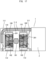
- Fig. 17 is a cross-sectional view of the outdoor unit of refrigeration cycle apparatus.
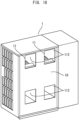
- Figs. 18 and 19 are front views of the outdoor unit of refrigeration cycle apparatus.
- Fig. 20 is a front view illustrating a modification of the outdoor unit of refrigeration cycle apparatus with the front panel removed from the outdoor unit.
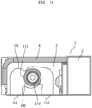
- Fig. 21 is a front view illustrating a first other example of the outdoor unit of refrigeration cycle apparatus with the front panel removed from the outdoor unit.
- Fig. 22 is a front view illustrating a second other example of the outdoor unit of refrigeration cycle apparatus with the front panel removed from the outdoor unit.
- Fig. 23 is a cross-sectional view illustrating the second other example of the outdoor unit of refrigeration cycle apparatus.
- Figs. 24 and 25 are front views illustrating the second other example of the outdoor unit of refrigeration cycle apparatus.
- Fig. 26 is a front view illustrating a modification of the outdoor unit of refrigeration cycle apparatus with the front panel removed from the outdoor unit.
- Fig. 27 is a front view illustrating the modification of the outdoor unit of refrigeration cycle apparatus.
- Fig. 28 is a perspective view of a blower included in the modification of the outdoor unit of refrigeration cycle apparatus.
- Fig. 29 is a cross-sectional view of the blower included in the modification of the outdoor unit of refrigeration cycle apparatus.
- each blower of the outdoor unit is provided with one discharge port.
- two or more discharge ports are provided to one blower.
- the outdoor unit of refrigeration cycle apparatus according to the second embodiment is described mainly focusing on differences from the first embodiment. Basically, descriptions of the same components as those in the first embodiment are omitted. In the descriptions below, the same or corresponding components as or to those in the first embodiment are basically denoted by the same reference signs as those used in the descriptions of the first embodiment.
- two blowers 100 are provided in the blower chamber 3 as illustrated in Figs. 16 and 17 .
- Two discharge ports 112 are formed on each of the scroll casings 110 of the blowers 100.
- each of the two blowers 100 has two discharge ports 112. Accordingly, the outdoor unit has a total of four discharge ports 112 in its entirety.
- the front panel 10 is provided on the front surface of a portion of the housing 1 where the blower chamber 3 is located.
- the outdoor-unit air outlets 11 are formed on the front panel 10. Note that as illustrated in Fig. 19 , the outdoor-unit air outlets 11 may be provided with the grid-like grilles 12.
- the outdoor-unit air outlets 11 are provided equal to the number of the discharge ports 112.
- the outdoor unit has a total of four discharge ports 112 in its entirety. Therefore, on the front panel 10, four outdoor-unit air outlets 11 are formed. The position and size of the outdoor-unit air outlets 11 are adjusted to match the position and size of their corresponding discharge ports 112. That is, when the front panel 10 is properly attached to the housing 1, the discharge ports 112 are located in their corresponding outdoor-unit air outlets 11.
- the plurality of discharge ports 112 are located in their corresponding outdoor-unit air outlets 11 on the front panel 10.
- the front surface of the housing, on which the front panel 10 is provided is the outlet placement surface.
- the plurality of discharge ports 112 are located on this outlet placement surface.
- the suction ports of each of the blowers 100 are located facing directions toward opposite left and right lateral surfaces of the housing 1. That is, the rotation axis of the blower 100 is positioned along the left-right direction.
- a total width of the discharge ports 112 in a direction horizontal with the housing 1 placed and parallel to the outlet placement surface is more than the width of the blower chamber 3 in the said direction.
- the direction horizontal with the housing 1 placed and parallel to the outlet placement surface is the left-right direction.
- the blower chamber 3 may be provided on the upper side of the housing 1, while the machine chamber 2 may be provided on the lower side of the housing 1.
- the suction ports of the blower 100 are oriented in directions toward opposite left and right lateral surfaces of the housing 1, so that air can be efficiently suctioned particularly from the outdoor-unit air inlets 5 provided on the lateral surface of the housing 1. This makes it possible to increase the airflow volume and improve heat exchange efficiency.
- the rotation axis of the blower 100 is positioned along the left-right direction. That is, the rotation axis of the impeller 200 is positioned parallel to the outlet placement surface described above.
- the impeller 200 it is preferable for the impeller 200 to have a fan diameter larger than a half of a width of the blower chamber 3 in a direction perpendicular to the outlet placement surface, that is, in the front-rear direction. Having the fan diameter as described above can further increase the airflow volume, and consequently makes it possible to achieve an even lower noise level and an even lower input.
- FIG. 21 illustrates a first other configuration example of the outdoor unit of refrigeration cycle apparatus according to the present embodiment.
- two blowers 100 are provided in the blower chamber 3 and arranged one above the other in the up-down direction.
- Fig. 21 only one of the two blowers 100 is illustrated.
- Two discharge ports 112 are formed on each of the scroll casings 110 of the blowers 100. In this manner, each of the two blowers 100 has two discharge ports 112. Accordingly, the outdoor unit has a total of four discharge ports 112 in its entirety.
- the plurality of discharge ports 112 are located in their corresponding outdoor-unit air outlets formed on the front panel (not illustrated).
- the front surface of the housing, on which the front panel is provided is the outlet placement surface.
- the plurality of discharge ports 112 are located on this outlet placement surface.
- the suction ports of each of the blowers 100 are located facing the directions toward the top surface and the bottom surface of the housing 1. That is, the rotation axis of the blower 100 is positioned along the up-down direction.
- a total width of the discharge ports 112 in a direction horizontal with the housing 1 placed and parallel to the outlet placement surface is more than the width of the blower chamber 3 in the said direction.
- the direction horizontal with the housing 1 placed and parallel to the outlet placement surface is the left-right direction.
- FIGs. 22 to 25 illustrate a second other configuration example of the outdoor unit of refrigeration cycle apparatus according to the present embodiment.
- one blower 100 is provided in the blower chamber 3.
- Two discharge ports 112 are formed on the scroll casing 110 of the blower 100.
- one blower 100 has two discharge ports 112. Accordingly, the outdoor unit has a total of two discharge ports 112 in its entirety.
- the front panel 10 is provided on the front surface of a portion of the housing 1 where the blower chamber 3 is located.
- the outdoor-unit air outlets 11 are formed on the front panel 10. Note that as illustrated in Fig. 25 , the outdoor-unit air outlets 11 may be provided with the grid-like grilles 12.
- the outdoor-unit air outlets 11 are provided equal to the number of the discharge ports 112.
- the outdoor unit has a total of two discharge ports 112 in its entirety. Therefore, on the front panel 10, two outdoor-unit air outlets 11 are formed. The position and size of the outdoor-unit air outlets 11 are adjusted to match the position and size of their corresponding discharge ports 112. That is, when the front panel 10 is properly attached to the housing 1, the discharge ports 112 are located in their corresponding outdoor-unit air outlets 11.
- the plurality of discharge ports 112 are located in their corresponding outdoor-unit air outlets 11 on the front panel 10.
- the front surface of the housing, on which the front panel 10 is provided is the outlet placement surface.
- the plurality of discharge ports 112 are located on this outlet placement surface.
- the suction ports of each of the blowers 100 are located facing the directions toward the front surface and the back surface of the housing 1. That is, the rotation axis of the blower 100 is positioned along the front-rear direction.
- a total width of the discharge ports 112 in a direction horizontal with the housing 1 placed and parallel to the outlet placement surface is more than the width of the blower chamber 3 in the said direction.
- the direction horizontal with the housing 1 placed and parallel to the outlet placement surface is the left-right direction.
- the suction port of the blower 100 is oriented in the direction toward the back surface of the housing 1, so that air can be efficiently suctioned particularly from the outdoor-unit air inlets 5 provided on the back surface of the housing 1. This makes it possible to increase the airflow volume and improve heat exchange efficiency.
- Figs. 26 to 29 illustrate a modification of the second other configuration example of the outdoor unit of refrigeration cycle apparatus according to the present embodiment.
- two or more discharge ports 112 for one blower 100 are arranged radially when viewed from the front side of the housing 1.
- six discharge ports 112 are provided to one blower 100.
- Each of the discharge ports 112 has, on its inner circumferential side, a shape of an arc of the circle centered at the rotation axis of the blower 100.
- each of the discharge ports 112 has, on its inner circumferential side, an arc shape made up of a portion of a circle concentric to the suction port of the blower 100.
- Each of the discharge ports 112 has, on its outer circumferential side, an arcuate shape made up of a portion of an ellipse centered at the rotation axis of the blower 100.
- the outdoor-unit air outlets 11 are provided equal to the number of the discharge ports 112.
- the outdoor unit has a total of six discharge ports 112 in its entirety. Therefore, on the front panel 10, six outdoor-unit air outlets 11 are formed. The position and size of the outdoor-unit air outlets 11 are adjusted to match the position and size of their corresponding discharge ports 112. That is, when the front panel 10 is properly attached to the housing 1, the discharge ports 112 are located in their corresponding outdoor-unit air outlets 11.
- the plurality of discharge ports 112 are located in their corresponding outdoor-unit air outlets 11 on the front panel 10.
- the front surface of the housing, on which the front panel 10 is provided is the outlet placement surface.
- the plurality of discharge ports 112 are located on this outlet placement surface.
- the suction ports of each blower 100 are located facing the directions toward the front surface and the back surface of the housing 1. That is, the rotation axis of the blower 100 is positioned along the front-rear direction.
- a total width of the discharge ports 112 in a direction horizontal with the housing 1 placed and parallel to the outlet placement surface is more than the width of the blower chamber 3 in the said direction.
- the direction horizontal with the housing 1 placed and parallel to the outlet placement surface is the left-right direction.
- the suction port of the blower 100 is oriented in the direction toward the back surface of the housing 1, so that air can be efficiently suctioned particularly from the outdoor-unit air inlets 5 provided on the back surface of the housing 1. This makes it possible to increase the airflow volume and improve heat exchange efficiency.
- the discharge ports 112 of the blower 100 are arranged radially, so that air can be suctioned into the suction port evenly from the spaces between the discharge ports 112, and can be delivered from many discharge ports 112. Consequently, a further increase in the airflow volume can be achieved.
- the present disclosure is applicable to an outdoor unit of refrigeration cycle apparatus, in which the outdoor unit includes a double inlet centrifugal blower in a blower chamber of a housing.
Landscapes
- Engineering & Computer Science (AREA)
- Chemical & Material Sciences (AREA)
- Combustion & Propulsion (AREA)
- Mechanical Engineering (AREA)
- General Engineering & Computer Science (AREA)
- Other Air-Conditioning Systems (AREA)
- Structures Of Non-Positive Displacement Pumps (AREA)
Abstract
Description
- The present disclosure relates to an outdoor unit of refrigeration cycle apparatus.
- An outside unit of air conditioner, in which an air heat exchanger and a blower are provided, has been known as using a centrifugal blower (sirocco fan) as the blower, and providing air inlets on at least a back side of a housing, while providing air outlets on any of a right side, a left side, or a top side of the housing, or on both the left and right sides of the housing (see, for example, PTL 1).
- [PTL 1]
JP H07-027369 A - However, in the outdoor unit of refrigeration cycle apparatus as disclosed in
PTL 1, the size of air outlets of the centrifugal blower tends to be comparatively small relative to the size of the housing of the outdoor unit, particularly, the size of the air heat exchanger. This results in a reduction in airflow volume compared to a conventional outdoor unit of the same size and having a propeller fan installed therein. It is thus difficult to obtain a sufficient airflow volume particularly when a static pressure external to the outdoor unit is high. In addition, the airflow volume is reduced, which makes it difficult to achieve sufficient pressure recovery. This leads to an increase in noise level and an increase in input. - The present disclosure has been made to solve such problems. It is an object of the present disclosure to provide an outdoor unit of refrigeration cycle apparatus, in which even when a static pressure external to the outdoor unit is high, the outdoor unit can still obtain a large airflow volume, and can therefore achieve a low noise level and a low input, while preventing an increase in size of the outdoor unit.
- An outdoor unit of refrigeration cycle apparatus according to the present disclosure includes a housing in which a machine chamber and a blower chamber are formed, the blower chamber being partitioned from the machine chamber, the machine chamber housing a compressor inside, the blower chamber housing a heat exchanger and a blower inside, the blower being located on a secondary side of the heat exchanger, wherein the blower is a double inlet centrifugal blower including: an impeller having a plurality of blades arranged in a circumferential direction around a rotation axis, and a scroll casing having a discharge port and two bellmouths which serve as suction ports, the scroll casing housing the impeller inside, a plurality of the discharge ports are provided, the plurality of the discharge ports are located on an outlet placement surface, the outlet placement surface being a front or top surface of the housing, and a total width of the plurality of the discharge ports in a direction horizontal with the housing placed and parallel to the outlet placement surface is more than a width of the blower chamber in said direction.
- The outdoor unit of refrigeration cycle apparatus according to the present disclosure achieves such effects that even when a static pressure external to the outdoor unit is high, the outdoor unit can still obtain a large airflow volume, and can therefore achieve a low noise level and a low input, while preventing an increase in size of the outdoor unit.
-
-
Fig. 1 is a front view of an outdoor unit of refrigeration cycle apparatus according to First Embodiment with a front panel removed from the outdoor unit. -
Fig. 2 is a transparent top view illustrating relevant parts of the outdoor unit of refrigeration cycle apparatus according to First Embodiment. -
Fig. 3 is a transparent side view illustrating the relevant parts of the outdoor unit of refrigeration cycle apparatus according to First Embodiment. -
Fig. 4 is a front view of the outdoor unit of refrigeration cycle apparatus according to First Embodiment. -
Fig. 5 is a front view of the outdoor unit of refrigeration cycle apparatus according to First Embodiment. -
Fig. 6 is a plan view of an impeller of a blower included in the outdoor unit according to First Embodiment. -
Fig. 7 is a cross-sectional view of the blower included in the outdoor unit according to First Embodiment. -
Fig. 8 is a plan view of the impeller of the blower included in the outdoor unit according to First Embodiment. -
Fig. 9 is a cross-sectional view of the impeller of the blower included in the outdoor unit according to First Embodiment. -
Fig. 10 is a perspective view of the impeller of the blower included in the outdoor unit according to First Embodiment. -
Fig. 11 is a transparent top view of relevant parts, illustrating another example of the outdoor unit of refrigeration cycle apparatus according to First Embodiment. -
Fig. 12 is a top view illustrating still another example of the outdoor unit of refrigeration cycle apparatus according to First Embodiment. -
Fig. 13 is a top view illustrating still another example of the outdoor unit of refrigeration cycle apparatus according to First Embodiment. -
Fig. 14 is a top view illustrating still another example of the outdoor unit of refrigeration cycle apparatus according to First Embodiment with a top panel removed from the outdoor unit. -
Fig. 15 is a transparent front view of relevant parts, illustrating still another example of the outdoor unit of refrigeration cycle apparatus according to First Embodiment. -
Fig. 16 is a front view of an outdoor unit of refrigeration cycle apparatus according to Second Embodiment with a front panel removed from the outdoor unit. -
Fig. 17 is a cross-sectional view of the outdoor unit of refrigeration cycle apparatus according to Second Embodiment. -
Fig. 18 is a front view of the outdoor unit of refrigeration cycle apparatus according to Second Embodiment. -
Fig. 19 is a front view of the outdoor unit of refrigeration cycle apparatus according to Second Embodiment. -
Fig. 20 is a front view illustrating a modification of the outdoor unit of refrigeration cycle apparatus according to Second Embodiment with the front panel removed from the outdoor unit. -
Fig. 21 is a front view illustrating a first other example of the outdoor unit of refrigeration cycle apparatus according to Second Embodiment with the front panel removed from the outdoor unit. -
Fig. 22 is a front view illustrating a second other example of the outdoor unit of refrigeration cycle apparatus according to Second Embodiment with the front panel removed from the outdoor unit. -
Fig. 23 is a cross-sectional view illustrating the second other example of the outdoor unit of refrigeration cycle apparatus according to Second Embodiment. -
Fig. 24 is a front view illustrating the second other example of the outdoor unit of refrigeration cycle apparatus according to Second Embodiment. -
Fig. 25 is a front view illustrating the second other example of the outdoor unit of refrigeration cycle apparatus according to Second Embodiment. -
Fig. 26 is a front view illustrating a modification of the outdoor unit of refrigeration cycle apparatus according to Second Embodiment with the front panel removed from the outdoor unit. -
Fig. 27 is a front view illustrating the modification of the outdoor unit of refrigeration cycle apparatus according to Second Embodiment. -
Fig. 28 is a perspective view of a blower included in the modification of the outdoor unit of refrigeration cycle apparatus according to Second Embodiment. -
Fig. 29 is a cross-sectional view of the blower included in the modification of the outdoor unit of refrigeration cycle apparatus according to Second Embodiment. - Embodiments of an outdoor unit of refrigeration cycle apparatus according to the present disclosure will be described below with reference to the accompanying drawings. Note that the same or equivalent components in the drawings are denoted by the same reference signs, and overlapping descriptions thereof are thus simplified or omitted as appropriate. In the descriptions below, for the sake of convenience, the positional relationship between structures may be expressed based on the state illustrated in the drawings. Note that the present disclosure is not limited to the embodiments described below, and it is possible to freely combine the embodiments, modify any constituent element in each embodiment, or omit any constituent element in each embodiment without departing from the scope of the present disclosure.
- A first embodiment of the present disclosure is described below with reference to
Figs. 1 to 15 . -
Fig. 1 is a front view of an outdoor unit of refrigeration cycle apparatus with a front panel removed from the outdoor unit.Fig. 2 is a transparent top view illustrating relevant parts of the outdoor unit of refrigeration cycle apparatus.Fig. 3 is a transparent side view illustrating the relevant parts of the outdoor unit of refrigeration cycle apparatus.Figs. 4 and 5 are front views of the outdoor unit of refrigeration cycle apparatus.Fig. 6 is a plan view of an impeller of a blower included in the outdoor unit.Fig. 7 is a cross-sectional view of the blower included in the outdoor unit.Fig. 8 is a plan view of the impeller of the blower included in the outdoor unit.Fig. 9 is a cross-sectional view of the impeller of the blower included in the outdoor unit.Fig. 10 is a perspective view of the impeller of the blower included in the outdoor unit.Fig. 11 is a transparent top view of relevant parts, illustrating another example of the outdoor unit of refrigeration cycle apparatus.Figs. 12 and13 are top views illustrating still another example of the outdoor unit of refrigeration cycle apparatus.Fig. 14 is a top view illustrating still another example of the outdoor unit of refrigeration cycle apparatus with a top panel removed from the outdoor unit.Fig. 15 is a transparent front view of relevant parts, illustrating still another example of the outdoor unit of refrigeration cycle apparatus. - A refrigeration cycle apparatus according to the present embodiment includes an indoor unit and an outdoor unit. In each of the indoor unit and the outdoor unit, a heat exchanger is provided. The heat exchanger in the indoor unit, and the heat exchanger in the outdoor unit are connected by a refrigerant pipe provided to allow for circulation of refrigerant. The refrigeration cycle apparatus serves as a heat pump that causes refrigerant flowing through the refrigerant pipe to circulate between the heat exchanger in the indoor unit and the heat exchanger in the outdoor unit, thereby to transfer heat between the heat exchanger in the indoor unit and the heat exchanger in the outdoor unit.
- As illustrated in
Figs. 1 to 5 , the outdoor unit of refrigeration cycle apparatus according to the present embodiment includes ahousing 1. Thehousing 1 has, for example, a cuboid outer shape. That is, in the illustrated configuration, thehousing 1 has a front surface, a back surface, a top surface, a bottom surface, and opposite left and right lateral surfaces. - In the
housing 1, amachine chamber 2 and ablower chamber 3 are formed. Themachine chamber 2 is located on one of the left and right sides of thehousing 1. Theblower chamber 3 is located on the other of the left and right sides of thehousing 1. Themachine chamber 2 and theblower chamber 3 are partitioned from each other. Themachine chamber 2 houses a compressor, an electrical component box, and the like (not illustrated) inside. Theblower chamber 3 houses aheat exchanger 4 andblowers 100 inside. - As illustrated in
Fig. 2 , outdoor-unit air inlets 5 are formed on the lateral surface and back surface of a portion of thehousing 1 where theblower chamber 3 is located. As illustrated inFigs. 4 and 5 , afront panel 10 is provided on the front surface of a portion of thehousing 1 where theblower chamber 3 is located. On thefront panel 10, outdoor-unit air outlets 11 are formed. The interior of theblower chamber 3 serves as an air passage extending from the outdoor-unit air inlets 5 to the outdoor-unit air outlets 11. Note that as illustrated inFig. 5 , the outdoor-unit air outlets 11 may be provided with grid-like grilles 12. In this case, thegrilles 12 may be attached to thefront panel 10, or may be provided integrally with thefront panel 10. - Inside the
blower chamber 3, theheat exchanger 4 is located in an L-shape in top view, extending from the lateral surface to the back surface of thehousing 1 on which the outdoor-unit air inlets 5 are provided. Theblowers 100 are located downstream of theheat exchanger 4 in the air passage in theblower chamber 3. In other words, theblowers 100 are located on the secondary side of theheat exchanger 4. - As illustrated in
Figs. 1 , and3 to 5 , threeblowers 100 are provided in theblower chamber 3 in a configuration example described here. In this configuration example, the threeblowers 100 are arranged one above the other in an up-down direction. Each of theblowers 100 is a so-called double inlet centrifugal blower. Theblower 100 includes animpeller 200, ascroll casing 110, amotor 101, and ashaft 102. - The
impeller 200 is a centrifugal fan configured to generate airflow in theblower 100. As illustrated inFig. 2 and other drawings, theimpeller 200 is housed inside thescroll casing 110. Theimpeller 200 is rotatable about a rotation axis inside thescroll casing 110. As illustrated inFig. 6 , theimpeller 200 has a plurality ofblades 210. The plurality ofblades 210 of theimpeller 200 are arranged in a circumferential direction around the rotation axis of theimpeller 200. - The
scroll casing 110 regulates a flow of air blown out from theimpeller 200. Thescroll casing 110 has two side walls and a peripheral wall. The side walls of thescroll casing 110 are provided on opposite sides of theimpeller 200 in a direction along the rotation axis of theimpeller 200. The peripheral wall of thescroll casing 110 is provided so as to surround theimpeller 200 from the radially outer side of theimpeller 200. The two side walls are located opposite to each other through the peripheral wall. - As illustrated in
Fig. 7 , twobellmouths 111 are formed on thescroll casing 110. The two bellmouths 111 on thescroll casing 110 serve as suction ports for theblower 100. Thebellmouths 111 are provided respectively on the two side walls of thescroll casing 110. The suction ports formed in thebellmouths 111 have a circular shape centered at the rotation axis of theimpeller 200. Note that the suction ports are not limited to having a circular shape, but may have other shapes such as an elliptical shape. Thebellmouth 111 regulates a flow of gas to be suctioned into theimpeller 200 and causes the regulated flow of gas to flow into the suction port of theimpeller 200. Thebellmouth 111 is formed in such a manner that its opening diameter gradually decreases from the outer part of thescroll casing 110 toward the inner part thereof. This allows air in the vicinity of the suction port to flow smoothly along thebellmouth 111 and flow efficiently into theimpeller 200 from the suction port. - On the
scroll casing 110, adischarge port 112 is formed. Thedischarge port 112 is an opening through which airflow generated in thescroll casing 110 by theimpeller 200 is discharged. The opening of thedischarge port 112 has, for example, a rectangular shape. However, the opening of thedischarge port 112 is not limited to having a rectangular shape. The plane of the opening of thedischarge port 112 is positioned parallel to the rotation axis of theimpeller 200. - The peripheral wall of the
scroll casing 110 guides the airflow generated by theimpeller 200 along its curved wall surface to thedischarge port 112. The peripheral wall is provided between the side walls opposite to each other. For example, the peripheral wall is located parallel to the direction along the rotation axis of theimpeller 200. Note that the peripheral wall may be inclined relative to the direction along the rotation axis of theimpeller 200, and is not limited to the configuration in which the peripheral wall is located parallel to the direction along the rotation axis. - The peripheral wall of the
scroll casing 110 is formed into a curved surface having an involute shape when viewed from a direction parallel to the rotation axis of theimpeller 200. The involute shape is formed based on, for example, a logarithmic spiral, an Archimedean spiral, or an involute curve. Due to this shape, the air delivered from theimpeller 200 smoothly flows through the gap between theimpeller 200 and the peripheral wall in the direction toward thedischarge port 112. This allows the static pressure of air in thescroll casing 110 to efficiently increase more toward thedischarge port 112. - In the descriptions below, the "rotation axis of the
impeller 200" may also be referred to as "rotation axis of theblower 100." Theblower 100 having the configuration as described above is a double inlet centrifugal blower configured to suction air from opposite end sides of the rotation axis of theblower 100 and to blow out the air in a direction perpendicular to the rotation axis of theblower 100. - The
motor 101 and theshaft 102 are shared between theblowers 100. That is, in the configuration example described here, onemotor 101 and oneshaft 102 are provided for the threeblowers 100. Themotor 101 is located outside thescroll casings 110 of theblowers 100. In the example illustrated inFig. 3 , themotor 101 is located further above the threeblowers 100 arranged vertically one above the other. Theshaft 102 transmits the rotational driving force of themotor 101 to theimpellers 200 of theblowers 100. Theblowers 100 are located in such a manner that the respective rotation axes of theimpellers 200 of theblowers 100 are aligned. Theshaft 102 is provided along the respective rotation axes of theimpellers 200 of theblowers 100. The center of theimpeller 200 of each of theblowers 100 is fixed to theshaft 102. - In the outdoor unit according to the present embodiment, a plurality of discharge ports is provided. In the example described here, three
blowers 100 are provided, each of which has onedischarge port 112. Accordingly, the outdoor unit has a total of threedischarge ports 112 in its entirety. The number of thedischarge ports 112 to be included in the outdoor unit is not limited to three. It is sufficient that the outdoor unit has two ormore discharge ports 112. - As described above, the outdoor-
unit air outlets 11 are formed on thefront panel 10 provided on the front surface of thehousing 1. Corresponding to thedischarge ports 112, the outdoor-unit air outlets 11 are provided equal to the number of thedischarge ports 112. That is, in the configuration example described here, three outdoor-unit air outlets 11 are formed on thefront panel 10. The position and size of the outdoor-unit air outlets 11 are adjusted to match the position and size of theircorresponding discharge ports 112. That is, when thefront panel 10 is properly attached to thehousing 1, thedischarge ports 112 are located in their corresponding outdoor-unit air outlets 11. - In this manner, the plurality of
discharge ports 112 are located in their corresponding outdoor-unit air outlets 11 on thefront panel 10. In the outdoor unit according to the present embodiment, the front surface of the housing, on which thefront panel 10 is provided, is an outlet placement surface. The plurality ofdischarge ports 112 are located on this outlet placement surface. In contrast, the suction ports of each of theblowers 100 are located facing the directions toward the top surface and the bottom surface of thehousing 1. That is, the rotation axis of theblower 100 is positioned along the up-down direction. - In the outdoor unit according to the present embodiment, a total width of the plurality of
discharge ports 112 is adjusted to be greater than a width of theblower chamber 3. The width of thedischarge port 112 and the width of theblower chamber 3 described herein refer to a width in a direction horizontal with thehousing 1 placed and parallel to the outlet placement surface described above. That is, a total width of thedischarge ports 112 in a direction horizontal with thehousing 1 placed and parallel to the outlet placement surface is more than the width of theblower chamber 3 in the said direction. Note that as described above, since the rotation axis of theblower 100 is positioned along the up-down direction, the direction horizontal with thehousing 1 placed can be rephrased as a direction perpendicular to the rotation axis of theblower 100. Therefore, as for the width of thedischarge port 112 and the width of theblower chamber 3, in other words, the total width of thedischarge ports 112 in the direction perpendicular to the rotation axis of theblower 100 and parallel to the outlet placement surface is more than the width of theblower chamber 3 in the said direction. - In the configuration example described here, the direction horizontal with the
housing 1 placed and parallel to the outlet placement surface is a left-right direction. That is, a dimension A illustrated inFig. 2 is the width of thedischarge port 112 in a direction horizontal with thehousing 1 placed and parallel to the outlet placement surface. A dimension B illustrated inFig. 2 is the width of theblower chamber 3 in a direction horizontal with thehousing 1 placed and parallel to the outlet placement surface. Likewise, each of dimensions A1, A2, and A3 illustrated inFig. 1 is the width of thedischarge port 112 in a direction horizontal with thehousing 1 placed and parallel to the outlet placement surface. The dimension B illustrated inFig. 1 is the width of theblower chamber 3 in a direction horizontal with thehousing 1 placed and parallel to the outlet placement surface. A total width of the plurality ofdischarge ports 112 is adjusted to be greater than the width of theblower chamber 3. That is, the relationship between the dimensions A1, A2, A3, and B expressed by the following expression (1) is satisfied.
- The outdoor unit of refrigeration cycle apparatus according to the present embodiment, which has the configuration as described above, can still obtain a large airflow volume even when a static pressure external to the outdoor unit is high, and can therefore achieve a low noise level and a low input without increasing the size of the outdoor unit.
- Note that in this configuration example, the rotation axis of the
blower 100 is positioned along the up-down direction. That is, the rotation axis of theimpeller 200 is positioned parallel to the outlet placement surface described above. In this case, it is preferable for theimpeller 200 to have a fan diameter larger than a half of a width of theblower chamber 3 in a direction perpendicular to the outlet placement surface, that is, in a front-rear direction. Having the fan diameter as described above can further increase the airflow volume, and consequently makes it possible to achieve an even lower noise level and an even lower input. - Next, an example of the configuration of the
blowers 100 included in the outdoor unit according to the present embodiment is described with reference toFigs. 8 to 10 . As described above, theblowers 100 are double inlet centrifugal blowers. Each of theblowers 100 includes theimpeller 200 that is a centrifugal fan. Theimpeller 200 includes amain plate portion 201,side plate portions 203, and a plurality ofblades 210. - The
main plate portion 201 is a disk-shaped member. At the central part of themain plate portion 201, aboss portion 202 is provided. At the center of theboss portion 202, a hole is formed through which theshaft 102 passes. At a circumferential edge part of themain plate portion 201, the plurality ofblades 210 are arranged radially in the circumferential direction of themain plate portion 201. Theblades 210 are provided on opposite plate surfaces of themain plate portion 201. - Each of the
blades 210 is connected at one end to themain plate portion 201, while being connected at the other end to theside plate portion 203. That is, each of the plurality ofblades 210 is located between themain plate portion 201 and theside plate portion 203. The plurality ofblades 210 are spaced apart from each other at regular intervals in the circumferential direction of themain plate portion 201. - The
side plate portions 203 are annular members. Each of theside plate portions 203 is fixed to outer circumferential-side end portions of the plurality ofblades 210 on the side opposite to themain plate portion 201. Theside plate portions 203 are provided on opposite sides with respect to the plate surface of themain plate portion 201. Theside plate portion 203 connects the plurality ofblades 210, thereby to maintain the positional relationship between the tip ends of theblades 210 and reinforce the plurality ofblades 210. - The
impeller 200 is rotationally driven about the rotation axis by driving of themotor 101. As theimpeller 200 rotates, gas external to theblower 100 is suctioned from the suction ports formed in the bellmouths of thescroll casing 110. As theimpeller 200 rotates, the air suctioned into the space surrounded by themain plate portion 201 and the plurality ofblades 210 passes through the spaces between theadjacent blades 210, and is delivered outward in the radial direction of theimpeller 200. - Each of the plurality of
blades 210 of theimpeller 200 has aturbo blade portion 211 and asirocco blade portion 212. Theturbo blade portion 211 is provided on the inner circumferential side relative to thesirocco blade portion 212 in the radial direction from the rotation axis of theimpeller 200 as the center. Conversely, thesirocco blade portion 212 is provided on the outer circumferential side relative to theturbo blade portion 211 in the radial direction from the rotation axis of theimpeller 200 as the center. Theturbo blade portion 211 constitutes a backward curved blade formed at an outlet angle equal to or smaller than 90 degrees. Thesirocco blade portion 212 constitutes a forward curved blade formed at an outlet angle larger than 90 degrees. The outlet angle is an angle formed between the center line of theblade 210 and the tangent of an outer diameter circle of theimpeller 200 at the intersection of the outer diameter circle of theimpeller 200 and the center line of theblade 210. The boundary between theturbo blade portion 211 and thesirocco blade portion 212 is illustrated by the dotted line inFig. 8 . Thesirocco blade portion 212 is not necessarily provided. However, the airflow volume of theblower 100 can be increased by providing thesirocco blade portion 212. - Particularly as illustrated in
Fig. 10 , each of the plurality ofblades 210 is formed such that on the inner circumferential side relative to an innercircumferential end portion 204, the height of theblade 210 from the plate surface of themain plate portion 201 is reduced more toward the inner circumferential side. Theturbo blade portion 211 includes the innercircumferential end portion 204. Note that the position of the innercircumferential end portion 204 is illustrated by the dot-and-dash line inFig. 8 . - As illustrated in
Fig. 2 , when theblower 100 is viewed from a direction parallel to the rotation axis of theblower 100, theturbo blade portion 211 is exposed from the suction port of theblower 100. With this configuration, theturbo blade portion 211 helps improve the pressure recovery performance of theblower 100. This makes it possible to achieve an even lower input. - Note that the
heat exchanger 4 is not limited to having an L-shape in top view. Other than the L-shape, as illustrated inFig. 11 , theheat exchanger 4 may have, for example, a U-shape or C-shape in top view. For another example, aplate heat exchanger 4 may be used. - As illustrated in
Figs. 2 and3 , in the configuration example described here, at a location in thescroll casing 110 near themain plate portion 201 of theimpeller 200, a protrudingportion 113 is provided protruding toward theheat exchanger 4. Therefore, a distance C between theheat exchanger 4 and the location in thescroll casing 110 near themain plate portion 201 of theimpeller 200, that is, the protrudingportion 113 is shorter than a distance D between theheat exchanger 4 and a location in thescroll casing 110 near theside plate portions 203 of theimpeller 200. With this configuration, the airflow having passed through theheat exchanger 4 is smoothly guided from the location near themain plate portion 201 of theimpeller 200 to the location near theside plate portions 203 of theimpeller 200 along the outer shape of thescroll casing 110, and then flows into the suction ports formed in the bellmouths on thescroll casing 110. Consequently, an inflow ability of the airflow from theheat exchanger 4 to theblower 100 can be improved to reduce the pressure loss, and an even lower input can be achieved. It is preferable that the tip end of the protrudingportion 113 of thescroll casing 110 is formed into an arc shape. This allows the airflow having passed through theheat exchanger 4 to be more smoothly guided, and makes it possible to further improve the inflow ability of the airflow from theheat exchanger 4 to theblower 100. - In the configuration example described above, the outlet placement surface is the front surface of the
housing 1. However, the outlet placement surface is not limited to being the front surface of thehousing 1, but may be any surface of thehousing 1. For example,Figs. 12 to 15 illustrate a configuration example when the outlet placement surface is the top surface of thehousing 1. As illustrated inFig. 12 , atop panel 20 is provided on the top surface of a portion of thehousing 1 where theblower chamber 3 is located. On thetop panel 20, the outdoor-unit air outlets 11 are formed. Note that as illustrated inFig. 13 , the outdoor-unit air outlets 11 may be provided with the grid-like grilles 12. In this case, thegrilles 12 may be attached to thetop panel 20, or may be provided integrally with thetop panel 20. - On the
top panel 20, corresponding to thedischarge ports 112, the outdoor-unit air outlets 11 are provided equal to the number of thedischarge ports 112. In the illustrated configuration example, threeblowers 100 are provided in theblower chamber 3, each of which has onedischarge port 112. Accordingly, the outdoor unit has a total of threedischarge ports 112 in its entirety. Therefore, on thetop panel 20, three outdoor-unit air outlets 11 are formed. The position and size of the outdoor-unit air outlets 11 are adjusted to match the position and size of theircorresponding discharge ports 112. That is, when thetop panel 20 is properly attached to thehousing 1, thedischarge ports 112 are located in their corresponding outdoor-unit air outlets 11. - In this manner, the plurality of
discharge ports 112 are located in their corresponding outdoor-unit air outlets 11 on thetop panel 20. In this configuration example, the top surface of the housing, on which thetop panel 20 is provided, is the outlet placement surface. The plurality ofdischarge ports 112 are located on this outlet placement surface. In contrast, as illustrated inFigs. 14 and 15 , the suction ports of each of theblowers 100 are located facing the directions toward the front surface and the back surface of thehousing 1. That is, the rotation axis of theblower 100 is positioned along the front-rear direction. - A total width of the plurality of
discharge ports 112 in a direction horizontal with thehousing 1 placed and parallel to the outlet placement surface is more than the width of theblower chamber 3 in the said direction. In this example, the direction horizontal with thehousing 1 placed and parallel to the outlet placement surface includes at least the left-right direction. Therefore, even in this example, in other words, the total width of thedischarge ports 112 in a direction perpendicular to the rotation axis of theblower 100 and parallel to the outlet placement surface is more than the width of theblower chamber 3 in the said direction. Even in the configuration example as described above, it is still possible to obtain a large airflow volume even when a static pressure external to the outdoor unit is high, and therefore achieve a low noise level and a low input without increasing the size of the outdoor unit. - A second embodiment of the present disclosure is described below with reference to
Figs. 16 to 29 .Fig. 16 is a front view of an outdoor unit of refrigeration cycle apparatus with a front panel removed from the outdoor unit.Fig. 17 is a cross-sectional view of the outdoor unit of refrigeration cycle apparatus.Figs. 18 and19 are front views of the outdoor unit of refrigeration cycle apparatus.Fig. 20 is a front view illustrating a modification of the outdoor unit of refrigeration cycle apparatus with the front panel removed from the outdoor unit.Fig. 21 is a front view illustrating a first other example of the outdoor unit of refrigeration cycle apparatus with the front panel removed from the outdoor unit.Fig. 22 is a front view illustrating a second other example of the outdoor unit of refrigeration cycle apparatus with the front panel removed from the outdoor unit.Fig. 23 is a cross-sectional view illustrating the second other example of the outdoor unit of refrigeration cycle apparatus.Figs. 24 and25 are front views illustrating the second other example of the outdoor unit of refrigeration cycle apparatus.Fig. 26 is a front view illustrating a modification of the outdoor unit of refrigeration cycle apparatus with the front panel removed from the outdoor unit.Fig. 27 is a front view illustrating the modification of the outdoor unit of refrigeration cycle apparatus.Fig. 28 is a perspective view of a blower included in the modification of the outdoor unit of refrigeration cycle apparatus.Fig. 29 is a cross-sectional view of the blower included in the modification of the outdoor unit of refrigeration cycle apparatus. - In the configuration of the outdoor unit in the first embodiment described above, each blower of the outdoor unit is provided with one discharge port. In contrast to this, in the second embodiment described here, two or more discharge ports are provided to one blower. Hereinafter, the outdoor unit of refrigeration cycle apparatus according to the second embodiment is described mainly focusing on differences from the first embodiment. Basically, descriptions of the same components as those in the first embodiment are omitted. In the descriptions below, the same or corresponding components as or to those in the first embodiment are basically denoted by the same reference signs as those used in the descriptions of the first embodiment.
- In an example of the outdoor unit of refrigeration cycle apparatus according to the present embodiment, two
blowers 100 are provided in theblower chamber 3 as illustrated inFigs. 16 and17 . Twodischarge ports 112 are formed on each of thescroll casings 110 of theblowers 100. In this manner, each of the twoblowers 100 has twodischarge ports 112. Accordingly, the outdoor unit has a total of fourdischarge ports 112 in its entirety. - As illustrated in
Fig. 18 , thefront panel 10 is provided on the front surface of a portion of thehousing 1 where theblower chamber 3 is located. On thefront panel 10, the outdoor-unit air outlets 11 are formed. Note that as illustrated inFig. 19 , the outdoor-unit air outlets 11 may be provided with the grid-like grilles 12. - On the
front panel 10, corresponding to thedischarge ports 112, the outdoor-unit air outlets 11 are provided equal to the number of thedischarge ports 112. In the illustrated configuration example, the outdoor unit has a total of fourdischarge ports 112 in its entirety. Therefore, on thefront panel 10, four outdoor-unit air outlets 11 are formed. The position and size of the outdoor-unit air outlets 11 are adjusted to match the position and size of theircorresponding discharge ports 112. That is, when thefront panel 10 is properly attached to thehousing 1, thedischarge ports 112 are located in their corresponding outdoor-unit air outlets 11. - In this manner, the plurality of
discharge ports 112 are located in their corresponding outdoor-unit air outlets 11 on thefront panel 10. In this configuration example, the front surface of the housing, on which thefront panel 10 is provided, is the outlet placement surface. The plurality ofdischarge ports 112 are located on this outlet placement surface. In contrast, the suction ports of each of theblowers 100 are located facing directions toward opposite left and right lateral surfaces of thehousing 1. That is, the rotation axis of theblower 100 is positioned along the left-right direction. A total width of thedischarge ports 112 in a direction horizontal with thehousing 1 placed and parallel to the outlet placement surface is more than the width of theblower chamber 3 in the said direction. In this example, the direction horizontal with thehousing 1 placed and parallel to the outlet placement surface is the left-right direction. Note that as illustrated inFig. 20 , theblower chamber 3 may be provided on the upper side of thehousing 1, while themachine chamber 2 may be provided on the lower side of thehousing 1. - Even in the configuration example as described above, it is still possible to obtain a large airflow volume even when a static pressure external to the outdoor unit is high, and therefore achieve a low noise level and a low input without increasing the size of the outdoor unit. The suction ports of the
blower 100 are oriented in directions toward opposite left and right lateral surfaces of thehousing 1, so that air can be efficiently suctioned particularly from the outdoor-unit air inlets 5 provided on the lateral surface of thehousing 1. This makes it possible to increase the airflow volume and improve heat exchange efficiency. - Note that in this configuration example, the rotation axis of the
blower 100 is positioned along the left-right direction. That is, the rotation axis of theimpeller 200 is positioned parallel to the outlet placement surface described above. In this case, it is preferable for theimpeller 200 to have a fan diameter larger than a half of a width of theblower chamber 3 in a direction perpendicular to the outlet placement surface, that is, in the front-rear direction. Having the fan diameter as described above can further increase the airflow volume, and consequently makes it possible to achieve an even lower noise level and an even lower input. - Next, several other examples of the outdoor unit of refrigeration cycle apparatus according to the present embodiment are described with reference to
Figs. 21 to 29 . First,Fig. 21 illustrates a first other configuration example of the outdoor unit of refrigeration cycle apparatus according to the present embodiment. In the first other configuration example, twoblowers 100 are provided in theblower chamber 3 and arranged one above the other in the up-down direction. InFig. 21 , only one of the twoblowers 100 is illustrated. Twodischarge ports 112 are formed on each of thescroll casings 110 of theblowers 100. In this manner, each of the twoblowers 100 has twodischarge ports 112. Accordingly, the outdoor unit has a total of fourdischarge ports 112 in its entirety. - The plurality of
discharge ports 112 are located in their corresponding outdoor-unit air outlets formed on the front panel (not illustrated). In this configuration example, the front surface of the housing, on which the front panel is provided, is the outlet placement surface. The plurality ofdischarge ports 112 are located on this outlet placement surface. In contrast, the suction ports of each of theblowers 100 are located facing the directions toward the top surface and the bottom surface of thehousing 1. That is, the rotation axis of theblower 100 is positioned along the up-down direction. A total width of thedischarge ports 112 in a direction horizontal with thehousing 1 placed and parallel to the outlet placement surface is more than the width of theblower chamber 3 in the said direction. In this example, the direction horizontal with thehousing 1 placed and parallel to the outlet placement surface is the left-right direction. Even in the configuration example as described above, it is still possible to obtain a large airflow volume even when a static pressure external to the outdoor unit is high, and therefore achieve a low noise level and a low input without increasing the size of the outdoor unit. - Next,
Figs. 22 to 25 illustrate a second other configuration example of the outdoor unit of refrigeration cycle apparatus according to the present embodiment. In the second other configuration example, as illustrated inFigs. 22 and23 , oneblower 100 is provided in theblower chamber 3. Twodischarge ports 112 are formed on thescroll casing 110 of theblower 100. In this manner, oneblower 100 has twodischarge ports 112. Accordingly, the outdoor unit has a total of twodischarge ports 112 in its entirety. - As illustrated in
Fig. 24 , thefront panel 10 is provided on the front surface of a portion of thehousing 1 where theblower chamber 3 is located. On thefront panel 10, the outdoor-unit air outlets 11 are formed. Note that as illustrated inFig. 25 , the outdoor-unit air outlets 11 may be provided with the grid-like grilles 12. - On the
front panel 10, corresponding to thedischarge ports 112, the outdoor-unit air outlets 11 are provided equal to the number of thedischarge ports 112. In the illustrated configuration example, the outdoor unit has a total of twodischarge ports 112 in its entirety. Therefore, on thefront panel 10, two outdoor-unit air outlets 11 are formed. The position and size of the outdoor-unit air outlets 11 are adjusted to match the position and size of theircorresponding discharge ports 112. That is, when thefront panel 10 is properly attached to thehousing 1, thedischarge ports 112 are located in their corresponding outdoor-unit air outlets 11. - In this manner, the plurality of
discharge ports 112 are located in their corresponding outdoor-unit air outlets 11 on thefront panel 10. In this configuration example, the front surface of the housing, on which thefront panel 10 is provided, is the outlet placement surface. The plurality ofdischarge ports 112 are located on this outlet placement surface. In contrast, the suction ports of each of theblowers 100 are located facing the directions toward the front surface and the back surface of thehousing 1. That is, the rotation axis of theblower 100 is positioned along the front-rear direction. A total width of thedischarge ports 112 in a direction horizontal with thehousing 1 placed and parallel to the outlet placement surface is more than the width of theblower chamber 3 in the said direction. In this example, the direction horizontal with thehousing 1 placed and parallel to the outlet placement surface is the left-right direction. - Even in the configuration example as described above, it is still possible to obtain a large airflow volume even when a static pressure external to the outdoor unit is high, and therefore achieve a low noise level and a low input without increasing the size of the outdoor unit. The suction port of the
blower 100 is oriented in the direction toward the back surface of thehousing 1, so that air can be efficiently suctioned particularly from the outdoor-unit air inlets 5 provided on the back surface of thehousing 1. This makes it possible to increase the airflow volume and improve heat exchange efficiency. -
Figs. 26 to 29 illustrate a modification of the second other configuration example of the outdoor unit of refrigeration cycle apparatus according to the present embodiment. In this modification, as illustrated inFigs. 26 ,28 , and29 , two ormore discharge ports 112 for oneblower 100 are arranged radially when viewed from the front side of thehousing 1. In the illustrated configuration example, sixdischarge ports 112 are provided to oneblower 100. Each of thedischarge ports 112 has, on its inner circumferential side, a shape of an arc of the circle centered at the rotation axis of theblower 100. In other words, each of thedischarge ports 112 has, on its inner circumferential side, an arc shape made up of a portion of a circle concentric to the suction port of theblower 100. Each of thedischarge ports 112 has, on its outer circumferential side, an arcuate shape made up of a portion of an ellipse centered at the rotation axis of theblower 100. - As illustrated in
Fig. 27 , on thefront panel 10, corresponding to thedischarge ports 112, the outdoor-unit air outlets 11 are provided equal to the number of thedischarge ports 112. In the illustrated configuration example, the outdoor unit has a total of sixdischarge ports 112 in its entirety. Therefore, on thefront panel 10, six outdoor-unit air outlets 11 are formed. The position and size of the outdoor-unit air outlets 11 are adjusted to match the position and size of theircorresponding discharge ports 112. That is, when thefront panel 10 is properly attached to thehousing 1, thedischarge ports 112 are located in their corresponding outdoor-unit air outlets 11. - In this manner, the plurality of
discharge ports 112 are located in their corresponding outdoor-unit air outlets 11 on thefront panel 10. In this configuration example, the front surface of the housing, on which thefront panel 10 is provided, is the outlet placement surface. The plurality ofdischarge ports 112 are located on this outlet placement surface. In contrast, the suction ports of eachblower 100 are located facing the directions toward the front surface and the back surface of thehousing 1. That is, the rotation axis of theblower 100 is positioned along the front-rear direction. A total width of thedischarge ports 112 in a direction horizontal with thehousing 1 placed and parallel to the outlet placement surface is more than the width of theblower chamber 3 in the said direction. In this example, the direction horizontal with thehousing 1 placed and parallel to the outlet placement surface is the left-right direction. - Even in the configuration example as described above, it is still possible to obtain a large airflow volume even when a static pressure external to the outdoor unit is high, and therefore achieve a low noise level and a low input without increasing the size of the outdoor unit. The suction port of the
blower 100 is oriented in the direction toward the back surface of thehousing 1, so that air can be efficiently suctioned particularly from the outdoor-unit air inlets 5 provided on the back surface of thehousing 1. This makes it possible to increase the airflow volume and improve heat exchange efficiency. Furthermore, thedischarge ports 112 of theblower 100 are arranged radially, so that air can be suctioned into the suction port evenly from the spaces between thedischarge ports 112, and can be delivered from many dischargeports 112. Consequently, a further increase in the airflow volume can be achieved. - The present disclosure is applicable to an outdoor unit of refrigeration cycle apparatus, in which the outdoor unit includes a double inlet centrifugal blower in a blower chamber of a housing.
-
- 1
- Housing
- 2
- Machine chamber
- 3
- Blower chamber
- 4
- Heat exchanger
- 5
- Outdoor-unit air inlets
- 10
- Front panel
- 11
- Outdoor-unit air outlets
- 12
- Grilles
- 20
- Top panel
- 100
- Blower
- 101
- Motor
- 102
- Shaft
- 110
- Scroll casing
- 111
- Bellmouths
- 112
- Discharge port
- 113
- Protruding portion
- 200
- Impeller
- 201
- Main plate portion
- 202
- Boss portion
- 203
- Side plate portions
- 204
- Inner circumferential end portion
- 210
- Blades
- 211
- Turbo blade portion
- 212
- Sirocco blade portion
Claims (10)
- An outdoor unit of refrigeration cycle apparatus comprising,a housing in which a machine chamber and a blower chamber are formed, the blower chamber being partitioned from the machine chamber, the machine chamber housing a compressor inside, the blower chamber housing a heat exchanger and a blower inside, the blower being located on a secondary side of the heat exchanger, whereinthe blower is a double inlet centrifugal blower including:an impeller having a plurality of blades arranged in a circumferential direction around a rotation axis, anda scroll casing having a discharge port and two bellmouths which serve as suction ports, the scroll casing housing the impeller inside,a plurality of the discharge ports are provided,the plurality of the discharge ports are located on an outlet placement surface, the outlet placement surface being a front or top surface of the housing, anda total width of the plurality of the discharge ports in a direction horizontal with the housing placed and parallel to the outlet placement surface is more than a width of the blower chamber in said direction.
- The outdoor unit of refrigeration cycle apparatus according to claim 1, whereineach of the plurality of blades of the impeller has a turbo blade portion constituting a backward curved blade formed at an outlet angle equal to or smaller than 90 degrees, andwhen the blower is viewed from a direction parallel to the rotation axis, the turbo blade portion is exposed from the suction port.
- The outdoor unit of refrigeration cycle apparatus according to claim 2, wherein each of the plurality of blades of the impeller further has a sirocco blade portion provided on an outer circumferential side relative to the turbo blade portion in a radial direction from the rotation axis as a center, and constituting a forward curved blade formed at an outlet angle larger than 90 degrees.
- The outdoor unit of refrigeration cycle apparatus according to any one of claims 1 to 3, whereinthe blower has two or more of the discharge ports,the outlet placement surface is a front surface of the housing, andthe suction ports of the blower are located facing directions toward the top surface and a bottom surface of the housing.
- The outdoor unit of refrigeration cycle apparatus according to any one of claims 1 to 3, whereinthe blower has two or more of the discharge ports,the outlet placement surface is the front surface of the housing, andthe suction ports of the blower are located facing directions toward opposite left and right lateral surfaces of the housing.
- The outdoor unit of refrigeration cycle apparatus according to any one of claims 1 to 5, whereinthe rotation axis of the impeller is positioned parallel to the outlet placement surface, andthe impeller has a fan diameter larger than a half of a width of the blower chamber in a direction perpendicular to the outlet placement surface.
- The outdoor unit of refrigeration cycle apparatus according to any one of claims 1 to 3, whereinthe blower has two or more of the discharge ports,the outlet placement surface is the front surface of the housing, andthe suction ports of the blower are located facing directions toward the front surface and a back surface of the housing.
- The outdoor unit of refrigeration cycle apparatus according to claim 7, wherein two or more of the discharge ports for the blower are arranged radially when viewed from a front side of the housing.
- The outdoor unit of refrigeration cycle apparatus according to any one of claims 1 to 8, wherein a distance between the heat exchanger and a location in the scroll casing near a main plate portion of the impeller is shorter than a distance between the heat exchanger and a location in the scroll casing near a side plate portion of the impeller.
- The outdoor unit of refrigeration cycle apparatus according to claim 9, wherein the location in the scroll casing near the main plate portion of the impeller has a protruding portion protruding toward the heat exchanger, and a tip end of the protruding portion is formed into an arc shape.
Applications Claiming Priority (1)
| Application Number | Priority Date | Filing Date | Title |
|---|---|---|---|
| PCT/JP2021/039323 WO2023073768A1 (en) | 2021-10-25 | 2021-10-25 | Outdoor unit of refrigeration cycle device |
Publications (2)
| Publication Number | Publication Date |
|---|---|
| EP4425060A1 true EP4425060A1 (en) | 2024-09-04 |
| EP4425060A4 EP4425060A4 (en) | 2025-05-14 |
Family
ID=86157507
Family Applications (1)
| Application Number | Title | Priority Date | Filing Date |
|---|---|---|---|
| EP21962318.8A Withdrawn EP4425060A4 (en) | 2021-10-25 | 2021-10-25 | OUTDOOR UNIT OF A REFRIGERATION CYCLE DEVICE |
Country Status (6)
| Country | Link |
|---|---|
| US (1) | US20240392979A1 (en) |
| EP (1) | EP4425060A4 (en) |
| JP (1) | JP7613606B2 (en) |
| CN (1) | CN118103637A (en) |
| TW (1) | TWI840912B (en) |
| WO (1) | WO2023073768A1 (en) |
Family Cites Families (20)
| Publication number | Priority date | Publication date | Assignee | Title |
|---|---|---|---|---|
| JPS553546A (en) * | 1978-06-20 | 1980-01-11 | Sanyo Electric Co | Airrcooled condenser |
| US5005372A (en) * | 1990-04-27 | 1991-04-09 | Thermo King Corporation | Air conditioner unit for mounting on or in the roof of a vehicle |
| JPH0727369A (en) * | 1993-07-15 | 1995-01-27 | Mitsubishi Heavy Ind Ltd | Outdoor machine for air conditioner |
| JPH10122602A (en) * | 1996-10-15 | 1998-05-15 | Daikin Ind Ltd | Outdoor unit for air conditioner |
| JP2000240590A (en) * | 1999-02-23 | 2000-09-05 | Hitachi Ltd | Multi-wing forward fan |
| JP2002357337A (en) | 2001-05-31 | 2002-12-13 | Daikin Ind Ltd | Air conditioner outdoor unit |
| JP3627673B2 (en) | 2001-05-31 | 2005-03-09 | ダイキン工業株式会社 | Air conditioner outdoor unit |
| JP2003004261A (en) | 2001-06-25 | 2003-01-08 | Daikin Ind Ltd | Air conditioner outdoor unit |
| JP3680148B2 (en) | 2001-07-24 | 2005-08-10 | ダイキン工業株式会社 | Air conditioner outdoor unit |
| JP2004012084A (en) | 2002-06-11 | 2004-01-15 | Hitachi Ltd | Outdoor unit for air conditioner |
| KR101085896B1 (en) * | 2004-08-13 | 2011-11-23 | 삼성전자주식회사 | Outdoor unit of air conditioner |
| JP5097576B2 (en) | 2008-02-29 | 2012-12-12 | 日立アプライアンス株式会社 | Indoor embedded heat source and air conditioner |
| JP5389076B2 (en) | 2011-03-08 | 2014-01-15 | 三菱電機株式会社 | Blower and air conditioner outdoor unit |
| JP5805598B2 (en) * | 2012-09-12 | 2015-11-04 | 三菱電機株式会社 | Refrigeration cycle equipment |
| JP7159804B2 (en) * | 2018-11-19 | 2022-10-25 | 株式会社デンソー | centrifugal blower |
| WO2020202420A1 (en) | 2019-04-01 | 2020-10-08 | 三菱電機株式会社 | Centrifugal blower, blowing device, air-conditioning device, and refrigeration cycle device |
| JP2020169788A (en) | 2019-04-05 | 2020-10-15 | ダイキン工業株式会社 | Heat pump device |
| CN115335607A (en) | 2020-03-19 | 2022-11-11 | 三菱电机株式会社 | Impeller, multi-wing blower and air conditioner |
| CN111853970A (en) * | 2020-08-28 | 2020-10-30 | 上海伯涵热能科技有限公司 | Air conditioner external unit with strip-shaped air outlets and air conditioner external unit and building outer vertical face combined module |
| CN113323914B (en) * | 2021-07-08 | 2025-05-30 | 珠海格力电器股份有限公司 | Centrifugal fans, air conditioners |
-
2021
- 2021-10-25 CN CN202180103225.8A patent/CN118103637A/en not_active Withdrawn
- 2021-10-25 JP JP2023555896A patent/JP7613606B2/en active Active
- 2021-10-25 EP EP21962318.8A patent/EP4425060A4/en not_active Withdrawn
- 2021-10-25 US US18/684,031 patent/US20240392979A1/en active Pending
- 2021-10-25 WO PCT/JP2021/039323 patent/WO2023073768A1/en not_active Ceased
-
2022
- 2022-08-11 TW TW111130219A patent/TWI840912B/en not_active IP Right Cessation
Also Published As
| Publication number | Publication date |
|---|---|
| JP7613606B2 (en) | 2025-01-15 |
| JPWO2023073768A1 (en) | 2023-05-04 |
| TWI840912B (en) | 2024-05-01 |
| EP4425060A4 (en) | 2025-05-14 |
| US20240392979A1 (en) | 2024-11-28 |
| TW202317922A (en) | 2023-05-01 |
| CN118103637A (en) | 2024-05-28 |
| WO2023073768A1 (en) | 2023-05-04 |
Similar Documents
| Publication | Publication Date | Title |
|---|---|---|
| TWI807298B (en) | Impellers, Centrifugal Fans and Air Conditioners | |
| TWI801735B (en) | Centrifugal fans and air conditioning units | |
| CN113710899A (en) | Impeller, multi-wing blower and air conditioning device | |
| CN112352108B (en) | Multi-blade blower and air conditioner | |
| US12196218B2 (en) | Impeller, multi-blade fan, and air-conditioning apparatus | |
| EP4400777A1 (en) | Ceiling-embedded air conditioner | |
| EP2472190B1 (en) | Fan unit and air conditioner equipped with fan unit | |
| US12320363B2 (en) | Centrifugal air-sending device and air-conditioning apparatus | |
| US12000602B2 (en) | Air-conditioning apparatus | |
| EP4425060A1 (en) | Outdoor unit of refrigeration cycle device | |
| CN113302401A (en) | Blower, indoor unit, and air conditioner | |
| EP3534015B1 (en) | Propeller fan, outdoor machine, and refrigeration cycle apparatus | |
| KR20210015280A (en) | The Air Conditioner | |
| WO2024122026A1 (en) | Outdoor unit of refrigeration cycle device | |
| JP2007285164A (en) | Sirocco fan and air conditioner | |
| JP7493609B2 (en) | Centrifugal blower and air conditioner | |
| TW202436799A (en) | Outdoor unit of refrigeration cycle apparatus | |
| WO2024038506A1 (en) | Refrigeration cycle device | |
| JP2025159927A (en) | Blower and indoor unit of air conditioner | |
| HK40085940A (en) | Centrifugal blower and air conditioning device | |
| JP2008144725A (en) | Centrifugal compressor |
Legal Events
| Date | Code | Title | Description |
|---|---|---|---|
| STAA | Information on the status of an ep patent application or granted ep patent |
Free format text: STATUS: THE INTERNATIONAL PUBLICATION HAS BEEN MADE |
|
| PUAI | Public reference made under article 153(3) epc to a published international application that has entered the european phase |
Free format text: ORIGINAL CODE: 0009012 |
|
| STAA | Information on the status of an ep patent application or granted ep patent |
Free format text: STATUS: REQUEST FOR EXAMINATION WAS MADE |
|
| 17P | Request for examination filed |
Effective date: 20240223 |
|
| AK | Designated contracting states |
Kind code of ref document: A1 Designated state(s): AL AT BE BG CH CY CZ DE DK EE ES FI FR GB GR HR HU IE IS IT LI LT LU LV MC MK MT NL NO PL PT RO RS SE SI SK SM TR |
|
| DAV | Request for validation of the european patent (deleted) | ||
| DAX | Request for extension of the european patent (deleted) | ||
| A4 | Supplementary search report drawn up and despatched |
Effective date: 20250414 |
|
| RIC1 | Information provided on ipc code assigned before grant |
Ipc: F24F 13/24 20060101ALI20250408BHEP Ipc: F24F 1/40 20110101ALI20250408BHEP Ipc: F24F 1/38 20110101AFI20250408BHEP |
|
| STAA | Information on the status of an ep patent application or granted ep patent |
Free format text: STATUS: THE APPLICATION HAS BEEN WITHDRAWN |
|
| 18W | Application withdrawn |
Effective date: 20250710 |