EP4425000A1 - Heat source unit of an air heat pump - Google Patents
Heat source unit of an air heat pump Download PDFInfo
- Publication number
- EP4425000A1 EP4425000A1 EP23159906.9A EP23159906A EP4425000A1 EP 4425000 A1 EP4425000 A1 EP 4425000A1 EP 23159906 A EP23159906 A EP 23159906A EP 4425000 A1 EP4425000 A1 EP 4425000A1
- Authority
- EP
- European Patent Office
- Prior art keywords
- fan
- louvers
- heat source
- source unit
- center
- Prior art date
- Legal status (The legal status is an assumption and is not a legal conclusion. Google has not performed a legal analysis and makes no representation as to the accuracy of the status listed.)
- Pending
Links
Images



Classifications
-
- F—MECHANICAL ENGINEERING; LIGHTING; HEATING; WEAPONS; BLASTING
- F04—POSITIVE - DISPLACEMENT MACHINES FOR LIQUIDS; PUMPS FOR LIQUIDS OR ELASTIC FLUIDS
- F04D—NON-POSITIVE-DISPLACEMENT PUMPS
- F04D29/00—Details, component parts, or accessories
- F04D29/70—Suction grids; Strainers; Dust separation; Cleaning
- F04D29/701—Suction grids; Strainers; Dust separation; Cleaning especially adapted for elastic fluid pumps
- F04D29/703—Suction grids; Strainers; Dust separation; Cleaning especially adapted for elastic fluid pumps specially for fans, e.g. fan guards
-
- F—MECHANICAL ENGINEERING; LIGHTING; HEATING; WEAPONS; BLASTING
- F04—POSITIVE - DISPLACEMENT MACHINES FOR LIQUIDS; PUMPS FOR LIQUIDS OR ELASTIC FLUIDS
- F04D—NON-POSITIVE-DISPLACEMENT PUMPS
- F04D29/00—Details, component parts, or accessories
- F04D29/40—Casings; Connections of working fluid
- F04D29/52—Casings; Connections of working fluid for axial pumps
- F04D29/54—Fluid-guiding means, e.g. diffusers
- F04D29/541—Specially adapted for elastic fluid pumps
- F04D29/542—Bladed diffusers
- F04D29/544—Blade shapes
-
- F—MECHANICAL ENGINEERING; LIGHTING; HEATING; WEAPONS; BLASTING
- F24—HEATING; RANGES; VENTILATING
- F24F—AIR-CONDITIONING; AIR-HUMIDIFICATION; VENTILATION; USE OF AIR CURRENTS FOR SCREENING
- F24F13/00—Details common to, or for air-conditioning, air-humidification, ventilation or use of air currents for screening
- F24F13/08—Air-flow control members, e.g. louvres, grilles, flaps or guide plates
- F24F13/082—Grilles, registers or guards
Definitions
- the present disclosure relates to a heat source unit of an air heat pump and particularly to the configuration of a grille thereof.
- an air heat pump comprises in its most simple form a refrigerant circuit connecting a usage side heat exchanger, a compressor, a heat source heat exchanger, and an expansion valve, wherein a refrigerant is circulated in the refrigerant circuit for transporting heat or cold from the heat source heat exchanger to the usage side heat exchanger.
- the heat source unit of such an air heat pump is in most cases installed outdoors and includes the heat source heat exchanger for exchanging heat between outside air and the refrigerant.
- the heat source unit comprises a casing, a fan accommodated in the casing and being rotatable about a center axis as well as a bell mouth having an opening centered on the center axis of the fan for allowing an air flow induced by the fan to pass and flow through the heat source heat exchanger.
- a grille or fan guard is provided covering the opening of the bell mouth and, hence, fan blades of the fan.
- Such a heat source unit is for example disclosed in EP 3 705 732 A1 .
- the grille comprises a plurality of horizontal louvers having a significant depth in a direction parallel to the center axis of the fan, whereby the fan is visually hidden when the grille is viewed in an angle relative to the center axis of the fan. As a result, the outer appearance is improved.
- the significant depth results in more obstructions to the air flow induced by the fan and consequently more vortexes being created.
- the vortexes may generate noises which are perceived negative, particularly if the heat source unit is placed nearby windows.
- the heat source unit of an air heat pump comprises a casing and a fan accommodated in the casing and being rotatable about a center axis.
- the heat source unit further comprises a bell mouth having an opening centered on the center axis of the fan for allowing an air flow induced by the fan to pass.
- the heat source unit may comprise the heat source heat exchanger of the heat pump as described earlier, wherein the air flow induced by the fan passes through the opening of the bell mouth and through the heat source heat exchanger in order to exchange heat/cold with the refrigerant flowing through the heat source heat exchanger.
- the opening of the bell mouth is covered by a grille.
- the grille or at least a portion thereof corresponding to the opening of the bell mouth comprises a plurality of longitudinal first louvers.
- First in this context intends to differentiate between first and second louvers within this disclosure but does not imply that there are necessarily two kinds of louvers. Taking this into account, the "first louvers” may also be referred to as guiding louvers in the sense that that they are intended to guide the air flow induced by the fan.
- the first louvers are longitudinal having a longitudinal extension/direction defined between a first end and a second end opposite to the first end.
- a center is defined between the first end and the second end.
- the first louvers have a depth being the dimension perpendicular to the longitudinal extension and parallel to the center axis of the fan as well as a height being the dimension perpendicular to the longitudinal extension and to the center axis of the fan.
- Each of the first louvers has an entry portion in its depth direction and facing the fan.
- the entry portion extends from a fan edge facing the fan in a direction towards the outside of the heat source unit. At least the entry portion is inclined relative to the center axis of the an.
- “at least the entry portion” encompasses an embodiment in which only a portion in the depth direction of the first louver is inclined and an embodiment in which the entire first louver is inclined in the depth direction of the first louver.
- the angle of inclination changes in the longitudinal direction of the respective first louver.
- the angle of inclination may continuously or gradually change in the longitudinal direction of the respective first louver.
- the angle of inclination may change stepwise (in steps).
- the angle of inclination, in a first portion between the first end and the center, decreases from a positive maximum angle towards the first end and the center. To put it differently, the angle of inclination is biggest at a position between the first end and the center and decreases from said position towards the first end and the center.
- the angle of inclination, in the first portion may continuously or gradually decrease from the positive maximum angle.
- the angle of inclination, in a second portion between the center and the second end increases from a negative maximum angle towards the center and the second end.
- the angle of inclination is smallest at a position between the center and the second end and increases from said position towards the center and the second end.
- the angle of inclination, in the second portion may continuously or gradually increase from the negative maximum angle.
- each of the first louvres is longitudinally twisted starting at the first end with a first angle (e.g. 0°) relative to the center axis of the fan in a first rotational direction to a maximum angle (maximum positive angle) relative to the center axis of the fan and from the maximum angle (maximum positive angle) in a second rotational direction opposite to the first rotational direction back to a second angle (e.g. 0) relative to the center axis of the fan at the center and/or starting at the center with the second angle (e.g. 0°) in the second rotational direction to the maximum angle (maximum negative angle) and from the maximum angle (maximum negative angle) in the first rotational direction back to the first angle (e.g. 0°) at the second end.
- a first angle e.g. 0°
- the absolute value of the positive maximum angle and the negative maximum angle may be the same considering the same first louver but may differ between two different first louvers (see later).
- the first louvers are at least partly inclined. It is assumed, that the air flow vector changes depending on the position on the radius relative to the center of the fan, particularly in an air flow region of the fan defined between two concentric rings. Therefore, the angle of inclination changes along the longitudinal direction of the first louvers. Therefore, the angle of inclination may correspond with the direction of the air flow (the air flow vector) induced by the fan at the respective position of the first louver. In particular, the angle of inclination may substantially be in line with the air flow direction (air flow vector) at the respective position of the first louver.
- the louvers are less obstructive and rather guide the air flow from the fan edge towards an outer edge decreasing the generation of vortexes. As a result, less noise occurs. Due to the first louvers being less obstructive, the fan may additionally be operated at lower RPM (rounds per minute) still achieving the same air flow rate, which further reduces noise. Thus, a more silent heat source unit is obtained
- the angle of inclination is 0° at the first end and the second end and/or at the center.
- the first louvers extend with their depth parallel to the center axis of the fan at the first end and the second end and/or at the center.
- the first louvers extend from one side of the grille to another opposite side of the grille.
- the first louvers may linearly extend from one side of the grille to another opposite side of the grille.
- the grille may be a front grille of a trunk-type heat source unit.
- the first louvers may horizontally (from the left to the right) or vertically (from the bottom to the top) extend from the one side to the other side.
- both the horizontal and vertical louvers comprise first louvers according to the present disclosure. Yet, for ease of manufacture, is preferred to either have the horizontal or the vertical louvers comprise the first louvers.
- the positive maximum angle may be located on one side (left/right or top/bottom) and the negative maximum angle may be located on the other side (right/left or bottom /top), i.e. the first end may be the left/right end or top/bottom end and the second end may be the right/left end or the bottom /top end.
- the grille may be a top grille of a top blow type heat source unit.
- the first louvers may horizontally extend from the one side to the other side. Further, in this case, first louvers may extend horizontally from the front to the back and/or from the left to the right.
- the positive maximum angle may be located on one side (left/right or front/back) and the negative maximum angle may be located on the other side (right/left or back/front), i.e. the first end may be the left/right end or front/back end and the second end may be the right/left end or back/front end.
- the first louvers are arranged in parallel, and the positive and negative maximum angle differ between first louvers in an arrangement direction of the louvers.
- the arrangement direction may also be referred to as the stacking direction when the first louvers are horizontal louvers.
- the grille further comprises non-inclined longitudinal second louvers.
- the terminology "second” is only used to differentiate the second louvers from the first louvers.
- the second louvers may also purely be referred to as non-inclined louvers.
- the first louvers of the grille are with respect to their inclination angle (angle of inclination) symmetric to a first straight line that passes the center axis of the fan and extends perpendicular to the center axis of the fan and/or to a second straight line that passes the center axis of the fan and extends perpendicular to the center axis of the fan and to the first line.
- angle of inclination is symmetric to a first straight line that passes the center axis of the fan and extends perpendicular to the center axis of the fan and/or to a second straight line that passes the center axis of the fan and extends perpendicular to the center axis of the fan and to the first line.
- the first louvers are radially extending louvers passing the center axis of the fan.
- the grille may be a circular grille or have a circular section in which the first louvers are provided.
- radially extending also encompasses first louvers which are curved in their longitudinal direction n but extend from the center towards the outside in a radial direction.
- the grille may have an even number of first louvres.
- the first louvres may be straight or curved diametrically passing the center from one outer circumferential edge to the opposite circumferential edge and with the positive maximum angle on one side and the negative maximum angle on the opposite side.
- the grille of this embodiment may also have first louvres being identical each extending from the center to an outer circumferential edge and being radially arranged.
- the first louvres have an angle of inclination which between the first end and the center, decreases from a positive maximum angle towards the first end and the center.
- the angle of inclination is biggest at a position between the first end and the center and decreases from said position towards the first end and the center.
- the angle of inclination, in the first portion may continuously or gradually decrease from the positive maximum angle.
- the grille may, hence, also have an uneven number.
- the first louvers have a depth perpendicular to their longitudinal direction and parallel to center axis of the fan of at least 15 mm, preferably at least 20mm, more preferably at least 25mm. Accordingly, the first louvers have a sufficiently large depth to, on the one hand, visually hide the fan viewing the grille in an angle relative to the center axis of the fan and, on the other hand, guide the air flow to avoid the generation of vortexes and, hence, noises. In this context, one needs to balance between a large depth beneficial for guiding the air flow and a short depth being less obstructive.
- the first louvers have an outer edge facing the outside of the heat source unit and an opposite fan edge facing the fan, wherein the fan edge is wave-shaped in a view parallel to the center axis of the fan and/or the outer edge is straight in a view parallel to the center axis of the fan.
- the wave shape of the fan edge provides for an easy adaption of the angle of inclination to the respective air flow vector at the respective position at the same time allowing the grille being injection molded.
- the outer edge being straight provides for a good visual appearance of the grille.
- the straight, e.g. parallel (horizontal) or concentric relative positioning of the outer edge further promotes parallel laminated airflow that reduces the creation of turbulence and therefore noises.
- the first and/or second louvers in cross-section perpendicular to their longitudinal direction have a rounded fan edge facing the fan.
- a rounded fan edge is less obstructive than a flat surface facing the fan, thereby reducing the generation of vortexes and hence noise.
- the first and/or second louvers in cross-section perpendicular to their longitudinal direction have a rounded outer edge facing the outside of the heat source unit. Due to the rounded outer edge turbulences at the outer edge may be reduced and, thereby, the generation of noise may be reduced.
- the radius of curvature of the rounded fan edge is equal to or larger than radius of curvature of the rounded outer edge.
- the first and second louvers represent a drop shape or air foil shape in cross section parallel to the center axis of the fan and perpendicular to their longitudinal extension. Such a drop shape reduces the generation of turbulences and provides therefore for a more silent heat source unit.
- the grille has a center portion centered with respect to the center axis of the fan, the center portion having a closed guide portion facing the fan, the guide portion being dome-shaped towards the fan. Due to the dome-shape, the air flow in the center is guided towards the first louvers, whereby a dead zone at the center is avoided. Additionally, the closed guide portion hides the center portion (hub) of the fan. Even further, the closed guide portion avoids reentry of the air flow which would cause extra turbulences inside the casing.
- the first louvers in cross-section perpendicular to their longitudinal direction and parallel to the center axis of the fan have the entry portion in which the first louver is inclined relative to the center axis of the fan and an exit portion at which the first louver is parallel to the center axis of the fan.
- the first louvers in cross-section perpendicular to their longitudinal direction and parallel to the center axis of the fan are curved. in other words, the entry portion at the exit portion connect via a curve.
- the fan is a propeller fan.
- a propeller fan is distinguished from a turbo fan or a scirocco fan.
- a propeller fan is the simple form of a fan mostly with a sheet metal or resin made, 3-6 bladed impeller directly driven by a motor mounted in the airstream or air flow.
- FIG 1 shows a trunk - type heat source unit 1 of an air heat pump. Yet, the present disclosure may also be embodied in a top - blow heat source unit.
- the heat source unit 1 comprises a casing 10 accommodating components of a refrigerant circuit of the air heat pump, such as the previously described heat source heat exchanger 20 (shown in figure 5 ). Also other components of the refrigerant circuit and/or the air heat pump may be accommodated in the casing 10, such as a compressor, an expansion valve, a controller or the like (not visible).
- the casing 10 comprises a top plate 12, a bottom plate 14 and a side plate 16 on the right.
- the plates 12, 14 and 16 may be made from sheet metal.
- the casing 10 may further comprise a back plate (not visible) particularly covering part of the backside of the heat source unit 1, particularly a portion corresponding to a machine chamber in which the other components of the refrigerant will be accommodated.
- the heat source heat exchanger 20 may, in top view, be L - shaped covering a side of the heat source unit opposite to the side plate 16 (shorter leg of the "L") as well as the remainder of the backside of the heat source unit 1 (longer leg of the "L”).
- a refrigerant will be flown through the heat source heat exchanger 20 for exchanging heat/cold with air.
- the term "heat” with respect to heat source heat exchanger 20 is used in a thermodynamic sense, that is “heat” is the amount of energy flowing from one body to another spontaneously due to their temperature difference no matter whether the "heat” is transferred from air to the refrigerant during heating operation or vice versa during cooling operation.
- the casing 10 accommodates a fan 22, in the present embodiment a propeller fan.
- a propeller fan is a comparatively simple form of a fan mostly with a sheet metal or resin made, 3-6 bladed impeller directly driven by a motor mounted in the airstream or air flow.
- the fan 22 comprises a hub 24 coupled to a motor 26 (see figure 5 ).
- a plurality of fan blades 28 are coupled to the hub 24.
- the fan 22 is, by operation of the motor 26, rotatable about a center axis 30 (axis of rotation).
- a bell mouth 32 is arranged in front of the fan 22 so that the fan 22 is arranged between the bell mouth 32 and the heat source heat exchanger 20.
- the bell mouth 32 has an opening 34, preferably a circular opening, being centered on the center axis 30 of the fan 22.
- a grille 40 is provided at the front of the casing 10 covering the opening 34 of the bell mouth 32.
- the grille 40 may be made of resin and be made in an injection molding process.
- the grille 40 extends for aesthetical purposes over the entire front of the casing 10 and comprises a fan portion 42 configured to allow air to pass through the grille 40 and a machine chamber portion 44 having a closed surface, not allowing air to pass and being primarily for design purposes.
- the present disclosure is particularly directed to the configuration of the fan portion 42.
- the fan portion 42 of the grille is meant.
- the grille 40 comprises a plurality of first louvers 46 (also referred to as guiding louvers or inclined louvers) and a plurality of second louvers 48 (also referred to as non-inclined louvers).
- the first louvers 46 and the second louvers 48 extend from one side 50 of the grille 40, or in this particular embodiment of the fan portion 42, (here the left side) to another opposite side 52 of the grille 40 or in this particular embodiment of the fan portion 42 (here the right side).
- the first and second louvers 46, 48 extend horizontally.
- the plurality of first and second louvers 46, 48 is arranged parallel to each other in an arrangement direction (here in a stacking direction from the bottom to the top).
- the distance between adjacent louvers 46, 48 may be between 20 mm and 40 mm or 25 mm to 35 mm.
- the first and second louvers 46, 48 have a fan edge 56 facing the fan 22 and an outer edge 58 facing the outside of the heat source unit 1 (the casing 10).
- the first and second louvers 46, 48 may have a rounded fan edge 56 and a rounded outer edge 58 as seen in a cross-section in the depth direction (perpendicular to the longitudinal extension, i.e. the length and the height).
- the radius of curvature of the rounded fan edge 56 and the rounded outer edge 58 may be the same.
- the radius of curvature of the rounded fan edge 56 may be larger than the radius of curvature of the rounded outer edge 58.
- the first and second louvers 46, 48 may have a cross-sectional shape resembling a drop or an airfoil.
- first louvers 46 and the second louvers 48 may be flush. I.e. lie in one common plane (e.g. on a planar plane perpendicular to the center axis 30 of the fan 22, a curved plane such as the sheath of a cylinder, the surface of a sphere or the like) for aesthetical purposes.
- the first and second louvers 46, 48 are longitudinal in that their length L is the biggest dimension as compared to depth D and height H. As the first and second louvers 46, 48 are flat or plate shaped, there height H (thickness) is smaller than their depth D.
- the depth D perpendicular to their longitudinal direction and parallel to center axis 30 of the fan 22 may be at least 15 mm, at least 20mm or at least 25 mm.
- the depth D should on the other hand not be larger than 55mm, 45mm or 35mm.
- the height H may be not more than 8mm, not more than 6mm or not mor than 5mm.
- the height may differ along their depth. In particular, the height H may be larger at the fan edge side then at the outer edge side.
- Three distinct zones of air flow A1, A2, A3 are defined by concentric rings in a view parallel to the center axis 30 of the fan 22. Only little air flow or an air flow with a relatively low air flow velocity is present in the outer zone A1 and only little to no air flow is present in the center zone A3. To the contrary, there is a high air flow or an air flow with a relatively high air flow velocity in the intermediate zone A2.
- the zones A1 to A3 are schematically indicated in figure 4 .
- the first louvers 46 are primarily arranged in an area crossing the opening 34 of the bell mouth 32 and, hence, in an area of air flow with significant air flow velocity. To put it differently, the first louvers 46 are primarily arranged in the intermediate zone A2. As the first louvers 46 however extend horizontally from the one side of the grille 40 to the other side of the grille 40 (here from left to right), some of the first louvers 46 will also traverse the center zone A3.
- the first louvers 46 have, along their longitudinal direction, (length L) a first end 60, a second end 62 opposite to the first end 60 and a center 64 between the first end 60 and the second end 62.
- the center 64 may be centered relative to the center axis 30 of the fan 22.
- Each of the first louvers 46 has, in the depth direction, an entry portion 66 facing the fan 22 and an exit portion 68 facing the outside of the heat source unit 1/the casing 10.
- the first louver 46 could be flat or plate shaped and be inclined relative to the center axis 30 of the fan 22. In other words, a line connecting the tip at the fan edge 56 and the tip at the outer edge 58 is straight but inclined relative to the center axis 30 of the fan 22.
- the air flow velocity decreases towards the borders to the outer zone A1 and the center zone A3 with a maximum angle at which the airflow approaches the fan edge 56 at an intermediate position between the borders to the outer zone A1 and the center zone A3.
- the angle at which the airflow approaches the fan edge 56 differs along the longitudinal direction of a respective first louver 46.
- the angle at which the airflow approaches the fan edge 56 may differ in the arrangement direction of the louvers. That is, the angle at which the airflow approaches the fan edge 56 at a specific position in the longitudinal direction of the respective louver may differ when considering an adjacent louver at the same specific position in the longitudinal direction. Additionally, a maximum angle at which the airflow approaches the fan edge 56 may differ in the arrangement direction of the louvers, that is adjacent louvers.
- One basic idea of the present disclosure is to incline at least the entry portion 66 of the first louvers 46 so as to match the angle at which the airflow approaches the fan edge 56 and the angle of inclination ⁇ at the respective position of the respective first louver 46 in its longitudinal direction.
- the angle of inclination ⁇ changes (here continuously or gradually changes, but alternatively may also change in steps) in the longitudinal direction of the respective first louver 46.
- the angle of inclination ⁇ in a first portion 70 between the first end 60 and the center 64, decreases from a positive maximum angle towards the first end 60 and the center 64.
- the angle of inclination ⁇ increases from a negative maximum angle towards the center 64 and the second end 62.
- the angle of inclination ⁇ is 0° at the first end 60, the second end 62 and in the center 64.
- the first louvers 46 are flat or plate shaped with their depth (entry portion and exit portion 66, 68) being parallel to the center axis 30 of the fan 22 at the first end 60, the second end 62 and in the center 64.
- the absolute value of the positive maximum angle and the negative maximum angle may reside in a range between 24° and 60°, preferably between 35° and 55°.
- the fan edge 56 is wave-shaped in a view parallel to the center axis 30 of the fan 22 (see figure 4 ).
- the outer edge 58 of the respective first louver 46 is straight in a view parallel to the center axis 30 of the fan 22 (here horizontal).
- the angle at which the airflow approaches the fan edge 56 may differ in the arrangement direction of the first louvers 46. That is, the angle at which the airflow approaches the fan edge 56 at a specific position in the longitudinal direction of the respective first louver 46 may differ when considering an adjacent first louver 46 at the same specific position in the longitudinal direction.
- the positive and negative maximum angle differ between first louvers 46, such as adjacent first louvers 46, in an arrangement direction of the first louvers 46.
- the configuration of the first louvers 46 with respect to the angle of inclination ⁇ is symmetric to a first straight line L1 that passes the center axis 30 of the fan 22 and extends in a first direction perpendicular to the center axis 30 of the fan 20 and/or to a second straight line L2 that passes the center axis 30 of the fan 22 and extends in a second direction perpendicular to the center axis 30 of the fan 22 and to the first direction (see figure 4 ).
- the configuration of the first louvers 46 is symmetric to both the first and second straight lines L1 and L2.
- first louvers 46 and their inclined entry portion 66 being adapted to the direction at which the airflow approaches the fan edge 56, turbulences and vortexes can be minimized. Accordingly, noise generation can be reduced.
- the first louvers 46 of the present disclosure are less obstructive so that the fan 22 may for achieving the same air flow through the heat source heat exchanger 20 be operated at lower RPM, which also assists in providing a silent heat source unit 1.
- the entry portion 66 of the first louvers 46 is inclined whereas the first louvers 46 are parallel to the center axis 30 of the fan 22 in the depth direction at the exit portion 68.
- the outer edges 58 of the first louvers 46 and the second louvers 48 are straight (here horizontal) and parallel to each other.
- the first louvers 46 may provide for an advantageous airflow guiding function, they are in cross-section perpendicular to their longitudinal direction and height direction curved (see figure 6 ). To put it differently, the entry portion 66 and the exit portion 68 are connected by a curved portion 78.
- the grille 40 (here the fan portion 42) has a center portion 74 centered with respect to the center axis 30 of the fan 22.
- the center portion 74 may be circular in a view parallel to the center axis 30 of the fan 22.
- the center portion 74 has a closed surface in order to prevent air from passing through the center portion 74.
- the middle part (hub 24) of the fan 22 is hidden and cannot be seen from the outside.
- the center portion 74 has a dome shaped guide portion 76 facing the fan 22 for guiding air towards openings in the grille 40.
- the second louvers 48 are primarily located in an area outside the opening 34 when viewed in a direction parallel to the center axis 30 of the fan 22 (here front view) at the top and bottom of the grille 40. Additional second louvers 48 may be provided within the area of the opening 34 when viewed in a direction parallel to the center axis 30 of the fan 22 (a front view) at the top and bottom of the grille 40 at which the air flow velocity is relatively low.
- the second louvers 48 are flat or plate shaped extending with their depth parallel to the center axis 30 of the fan 22 and with their length (longitudinal direction) perpendicular to the center axis 30 of the fan 22.
- the depth of the second louvers 48 may be the same as that of the first louvers 46.
- the grille 40 further comprises a third louvers 54 extending perpendicularly to the first and second louvers 46, 48 (here in a direction from the bottom plate 14 to the top plate 12).
- the third louvers 54 extend vertically.
- the third louvers 54 are smaller in depth than the first and a second louvers 46, 48.
- the third louvers 54 are in the present embodiment non-inclined, that is flat or plate shaped.
- the main purpose of the third louvers 54 is to realize finger and child finger safety, that is to prevent a person from reaching the fan 22 with the finger.
- first louvers 46 horizontal louvers
- the first louvers 46 are inclined or provided with the inclined entry portion. Accordingly, ease of manufacture in an injection molding process may be maintained.
- some of the third louvers 54 may have the same configuration as the first louvers 46 in the above embodiment.
- the configuration of the first louvers 46 may be rotated by 90 degrees and applied to the third louvers 54.
- the first louvers 46 extend radially. Even though the radial first louvers 46 have been shown as straight, the first louvers 46 could also extend in a radial direction but be curved as for example shown in EP 3 705 732 A1 . Different to the first embodiment, the absolute value of the positive maximum angle and negative maximum angle may be the same for all first louvers 46 because the respective position along the length L of the respective first lover 46 with respect to the fan 22 and the corresponding airflow direction induced by the fan 22 will be the same due to the radial arrangement of the first louvers 46.
- the radially extending first louvers are further connected by concentric third louvers 54.
Landscapes
- Engineering & Computer Science (AREA)
- Mechanical Engineering (AREA)
- General Engineering & Computer Science (AREA)
- Physics & Mathematics (AREA)
- Geometry (AREA)
- Structures Of Non-Positive Displacement Pumps (AREA)
- Other Air-Conditioning Systems (AREA)
- Air-Flow Control Members (AREA)
Abstract
The present disclosure relates to a heat source unit (1) of an air heat pump, having a casing (10), a fan accommodated in the casing (10) and being rotatable about a center axis (30), a bell mouth (32) having an opening (32) centered on the center axis (30) of the fan (22) for allowing an air flow induced by the fan (22) to pass, and a grille (40, 42) covering the opening (32). The grille (40, 42) comprises a plurality of longitudinal first louvers (46) having a first end (60), a second end opposite to the first end (60) and a center (64) between the first end (60) and the second end (62), wherein each of the first louvers (46) has an entry portion (66) facing the fan (22) and at least the entry portion (66) is inclined relative to the center axis (30) of the fan (22), wherein the angle of inclination (a) changes in the longitudinal direction of the respective first louver (46), wherein the angle of inclination (α), in a first portion (70) between the first end (60) and the center (64), decreases from a positive maximum angle towards the first end (60) and the center (64), and, in a second portion (72) between the center (64) and the second end (62), increases from a negative maximum angle towards the center (64) and the second end (62).
Description
- The present disclosure relates to a heat source unit of an air heat pump and particularly to the configuration of a grille thereof.
- In general, an air heat pump comprises in its most simple form a refrigerant circuit connecting a usage side heat exchanger, a compressor, a heat source heat exchanger, and an expansion valve, wherein a refrigerant is circulated in the refrigerant circuit for transporting heat or cold from the heat source heat exchanger to the usage side heat exchanger.
- The heat source unit of such an air heat pump is in most cases installed outdoors and includes the heat source heat exchanger for exchanging heat between outside air and the refrigerant. For this purpose, the heat source unit comprises a casing, a fan accommodated in the casing and being rotatable about a center axis as well as a bell mouth having an opening centered on the center axis of the fan for allowing an air flow induced by the fan to pass and flow through the heat source heat exchanger.
- In order to comply with industrial standards and regulations, a grille or fan guard is provided covering the opening of the bell mouth and, hence, fan blades of the fan.
- Such a heat source unit is for example disclosed in
EP 3 705 732 A1 . The grille comprises a plurality of horizontal louvers having a significant depth in a direction parallel to the center axis of the fan, whereby the fan is visually hidden when the grille is viewed in an angle relative to the center axis of the fan. As a result, the outer appearance is improved. - Yet, the significant depth results in more obstructions to the air flow induced by the fan and consequently more vortexes being created. The vortexes may generate noises which are perceived negative, particularly if the heat source unit is placed nearby windows.
- Taking the aforesaid into account, it is an object of the present disclosure to provide a heat source unit of an air heat pump which is more silent in operation meanwhile preserving maximal airflow and limiting the visibility of the fan.
- This object is solved by a heat source unit as defined in claim 1. Embodiments of the heat source unit are defined in the dependent claims.
- According to a first aspect, the heat source unit of an air heat pump comprises a casing and a fan accommodated in the casing and being rotatable about a center axis. The heat source unit further comprises a bell mouth having an opening centered on the center axis of the fan for allowing an air flow induced by the fan to pass. Additionally, the heat source unit may comprise the heat source heat exchanger of the heat pump as described earlier, wherein the air flow induced by the fan passes through the opening of the bell mouth and through the heat source heat exchanger in order to exchange heat/cold with the refrigerant flowing through the heat source heat exchanger. In order to comply with industrial standards and regulations, e.g. regarding finger safety, the opening of the bell mouth is covered by a grille. The grille or at least a portion thereof corresponding to the opening of the bell mouth comprises a plurality of longitudinal first louvers. "First" in this context intends to differentiate between first and second louvers within this disclosure but does not imply that there are necessarily two kinds of louvers. Taking this into account, the "first louvers" may also be referred to as guiding louvers in the sense that that they are intended to guide the air flow induced by the fan.
- The first louvers are longitudinal having a longitudinal extension/direction defined between a first end and a second end opposite to the first end. A center is defined between the first end and the second end. Further, the first louvers have a depth being the dimension perpendicular to the longitudinal extension and parallel to the center axis of the fan as well as a height being the dimension perpendicular to the longitudinal extension and to the center axis of the fan.
- Each of the first louvers has an entry portion in its depth direction and facing the fan. In other words, the entry portion extends from a fan edge facing the fan in a direction towards the outside of the heat source unit. At least the entry portion is inclined relative to the center axis of the an. In this context, "at least the entry portion" encompasses an embodiment in which only a portion in the depth direction of the first louver is inclined and an embodiment in which the entire first louver is inclined in the depth direction of the first louver.
- According to the first aspect, the angle of inclination changes in the longitudinal direction of the respective first louver. The angle of inclination may continuously or gradually change in the longitudinal direction of the respective first louver. Alternatively, the angle of inclination may change stepwise (in steps).
- The angle of inclination, in a first portion between the first end and the center, decreases from a positive maximum angle towards the first end and the center. To put it differently, the angle of inclination is biggest at a position between the first end and the center and decreases from said position towards the first end and the center. The angle of inclination, in the first portion, may continuously or gradually decrease from the positive maximum angle.
- Alternatively or additionally, the angle of inclination, in a second portion between the center and the second end, increases from a negative maximum angle towards the center and the second end. To put it differently, the angle of inclination is smallest at a position between the center and the second end and increases from said position towards the center and the second end. The angle of inclination, in the second portion, may continuously or gradually increase from the negative maximum angle.
- To put it differently, each of the first louvres is longitudinally twisted starting at the first end with a first angle (e.g. 0°) relative to the center axis of the fan in a first rotational direction to a maximum angle (maximum positive angle) relative to the center axis of the fan and from the maximum angle (maximum positive angle) in a second rotational direction opposite to the first rotational direction back to a second angle (e.g. 0) relative to the center axis of the fan at the center and/or starting at the center with the second angle (e.g. 0°) in the second rotational direction to the maximum angle (maximum negative angle) and from the maximum angle (maximum negative angle) in the first rotational direction back to the first angle (e.g. 0°) at the second end.
- The absolute value of the positive maximum angle and the negative maximum angle may be the same considering the same first louver but may differ between two different first louvers (see later).
- According to the first aspect, the first louvers are at least partly inclined. It is assumed, that the air flow vector changes depending on the position on the radius relative to the center of the fan, particularly in an air flow region of the fan defined between two concentric rings. Therefore, the angle of inclination changes along the longitudinal direction of the first louvers. Therefore, the angle of inclination may correspond with the direction of the air flow (the air flow vector) induced by the fan at the respective position of the first louver. In particular, the angle of inclination may substantially be in line with the air flow direction (air flow vector) at the respective position of the first louver.
- Consequently, the louvers are less obstructive and rather guide the air flow from the fan edge towards an outer edge decreasing the generation of vortexes. As a result, less noise occurs. Due to the first louvers being less obstructive, the fan may additionally be operated at lower RPM (rounds per minute) still achieving the same air flow rate, which further reduces noise. Thus, a more silent heat source unit is obtained
- According to a second aspect, the angle of inclination is 0° at the first end and the second end and/or at the center. In other words, the first louvers extend with their depth parallel to the center axis of the fan at the first end and the second end and/or at the center.
- According to the third aspect, the first louvers extend from one side of the grille to another opposite side of the grille. According to an embodiment, the first louvers may linearly extend from one side of the grille to another opposite side of the grille. The grille may be a front grille of a trunk-type heat source unit. In this case, the first louvers may horizontally (from the left to the right) or vertically (from the bottom to the top) extend from the one side to the other side. It is also conceivable that both the horizontal and vertical louvers comprise first louvers according to the present disclosure. Yet, for ease of manufacture, is preferred to either have the horizontal or the vertical louvers comprise the first louvers. In this context and depending on the direction of rotation of the fan, the positive maximum angle may be located on one side (left/right or top/bottom) and the negative maximum angle may be located on the other side (right/left or bottom /top), i.e. the first end may be the left/right end or top/bottom end and the second end may be the right/left end or the bottom /top end. Alternatively, the grille may be a top grille of a top blow type heat source unit. In this case, the first louvers may horizontally extend from the one side to the other side. Further, in this case, first louvers may extend horizontally from the front to the back and/or from the left to the right. Also here, the positive maximum angle may be located on one side (left/right or front/back) and the negative maximum angle may be located on the other side (right/left or back/front), i.e. the first end may be the left/right end or front/back end and the second end may be the right/left end or back/front end.
- According to a fourth aspect, the first louvers are arranged in parallel, and the positive and negative maximum angle differ between first louvers in an arrangement direction of the louvers. In case of a trunk type heat source unit, the arrangement direction may also be referred to as the stacking direction when the first louvers are horizontal louvers.
- According to a fifth aspect the grille further comprises non-inclined longitudinal second louvers. As particularized above, the terminology "second" is only used to differentiate the second louvers from the first louvers. The second louvers may also purely be referred to as non-inclined louvers. In particular, there may be regions of the grille in which there is no or only very little air flow so that there is no necessity to provide an angle of inclination. Rather, the second louvers extend with their depth parallel to the center axis of the fan and are, hence, non-inclined.
- According to sixth aspect the first louvers of the grille are with respect to their inclination angle (angle of inclination) symmetric to a first straight line that passes the center axis of the fan and extends perpendicular to the center axis of the fan and/or to a second straight line that passes the center axis of the fan and extends perpendicular to the center axis of the fan and to the first line. It is assumed, that the air flow induced by the fan is symmetric as are the air flow vectors. As previously indicated, the angle of inclination is corresponded to the respective air flow direction (air flow vector). Consequently it is preferred that also the first louvers are symmetric with respect to their angle of inclination.
- In an alternative embodiment, the first louvers are radially extending louvers passing the center axis of the fan. In particular, the grille may be a circular grille or have a circular section in which the first louvers are provided. In this context, radially extending also encompasses first louvers which are curved in their longitudinal direction n but extend from the center towards the outside in a radial direction. The grille may have an even number of first louvres. In this case the first louvres may be straight or curved diametrically passing the center from one outer circumferential edge to the opposite circumferential edge and with the positive maximum angle on one side and the negative maximum angle on the opposite side. The grille of this embodiment may also have first louvres being identical each extending from the center to an outer circumferential edge and being radially arranged. In this case, the first louvres have an angle of inclination which between the first end and the center, decreases from a positive maximum angle towards the first end and the center. To put it differently, the angle of inclination is biggest at a position between the first end and the center and decreases from said position towards the first end and the center. The angle of inclination, in the first portion, may continuously or gradually decrease from the positive maximum angle. The grille may, hence, also have an uneven number.
- According to an eighth aspect, the first louvers have a depth perpendicular to their longitudinal direction and parallel to center axis of the fan of at least 15 mm, preferably at least 20mm, more preferably at least 25mm. Accordingly, the first louvers have a sufficiently large depth to, on the one hand, visually hide the fan viewing the grille in an angle relative to the center axis of the fan and, on the other hand, guide the air flow to avoid the generation of vortexes and, hence, noises. In this context, one needs to balance between a large depth beneficial for guiding the air flow and a short depth being less obstructive.
- According to a ninth aspect, the first louvers have an outer edge facing the outside of the heat source unit and an opposite fan edge facing the fan, wherein the fan edge is wave-shaped in a view parallel to the center axis of the fan and/or the outer edge is straight in a view parallel to the center axis of the fan. The wave shape of the fan edge provides for an easy adaption of the angle of inclination to the respective air flow vector at the respective position at the same time allowing the grille being injection molded. The outer edge being straight provides for a good visual appearance of the grille. The straight, e.g. parallel (horizontal) or concentric relative positioning of the outer edge further promotes parallel laminated airflow that reduces the creation of turbulence and therefore noises.
- According to a tenth aspect, the first and/or second louvers in cross-section perpendicular to their longitudinal direction have a rounded fan edge facing the fan. A rounded fan edge is less obstructive than a flat surface facing the fan, thereby reducing the generation of vortexes and hence noise.
- According to an eleventh aspect, the first and/or second louvers in cross-section perpendicular to their longitudinal direction have a rounded outer edge facing the outside of the heat source unit. Due to the rounded outer edge turbulences at the outer edge may be reduced and, thereby, the generation of noise may be reduced.
- According to a twelfth aspect, the radius of curvature of the rounded fan edge is equal to or larger than radius of curvature of the rounded outer edge. As a result, the first and second louvers represent a drop shape or air foil shape in cross section parallel to the center axis of the fan and perpendicular to their longitudinal extension. Such a drop shape reduces the generation of turbulences and provides therefore for a more silent heat source unit.
- According to a thirteenth aspect, the grille has a center portion centered with respect to the center axis of the fan, the center portion having a closed guide portion facing the fan, the guide portion being dome-shaped towards the fan. Due to the dome-shape, the air flow in the center is guided towards the first louvers, whereby a dead zone at the center is avoided. Additionally, the closed guide portion hides the center portion (hub) of the fan. Even further, the closed guide portion avoids reentry of the air flow which would cause extra turbulences inside the casing.
- According to a fourteenth aspect, the first louvers in cross-section perpendicular to their longitudinal direction and parallel to the center axis of the fan have the entry portion in which the first louver is inclined relative to the center axis of the fan and an exit portion at which the first louver is parallel to the center axis of the fan.
- According to a fifteenth aspect, the first louvers in cross-section perpendicular to their longitudinal direction and parallel to the center axis of the fan are curved. in other words, the entry portion at the exit portion connect via a curve.
- According to a sixteenth aspect, the fan is a propeller fan. A propeller fan is distinguished from a turbo fan or a scirocco fan. A propeller fan is the simple form of a fan mostly with a sheet metal or resin made, 3-6 bladed impeller directly driven by a motor mounted in the airstream or air flow.
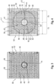
- The embodiments of the present disclosure are described below with respect to the accompanying drawings, in which
- Figure 1
- is a perspective view of a heat source unit according to a first embodiment.
- Figure 2
- is a perspective view on the fan side of the grille of the first embodiment.
- Figure 3
- is a front view of the grille of the first embodiment.
- Figure 4
- is a back view of the grille of the first embodiment.
- Figure 5A
- is a cross-sectional view of the heat source unit of the first embodiment along the
line 5A-5A infigure 1 . - Figure 5B
- is a cross-sectional view of the heat source unit of the first embodiment along the
line 5B-5B infigure 1 . - Figure 5C
- is a cross-sectional view of the heat source unit of the first embodiment along the
line 5C-5C infigure 1 . - Figure 6A
- to C are cross-sectional views of the isolated grille of
figure 5A to C . - Figure 7
- is a perspective front view of a grille of a second embodiment.
- Figure 8
- is a side view of the grille of
figure 7 . - Figure 9
- is a front view of the grille of the second embodiment.
- Figure 10
- is a back view of the grille of the second embodiment.
- The same reference numerals have been used in the following description and the drawings for the same or similar features throughout the embodiments.
-
Figure 1 shows a trunk - type heat source unit 1 of an air heat pump. Yet, the present disclosure may also be embodied in a top - blow heat source unit. The heat source unit 1 comprises acasing 10 accommodating components of a refrigerant circuit of the air heat pump, such as the previously described heat source heat exchanger 20 (shown infigure 5 ). Also other components of the refrigerant circuit and/or the air heat pump may be accommodated in thecasing 10, such as a compressor, an expansion valve, a controller or the like (not visible). - The
casing 10 comprises atop plate 12, abottom plate 14 and aside plate 16 on the right. Theplates casing 10 may further comprise a back plate (not visible) particularly covering part of the backside of the heat source unit 1, particularly a portion corresponding to a machine chamber in which the other components of the refrigerant will be accommodated. - The heat
source heat exchanger 20 may, in top view, be L - shaped covering a side of the heat source unit opposite to the side plate 16 (shorter leg of the "L") as well as the remainder of the backside of the heat source unit 1 (longer leg of the "L"). In use, a refrigerant will be flown through the heatsource heat exchanger 20 for exchanging heat/cold with air. In this context, the term "heat" with respect to heatsource heat exchanger 20 is used in a thermodynamic sense, that is "heat" is the amount of energy flowing from one body to another spontaneously due to their temperature difference no matter whether the "heat" is transferred from air to the refrigerant during heating operation or vice versa during cooling operation. - For flowing air through the heat
source heat exchanger 20, thecasing 10 accommodates afan 22, in the present embodiment a propeller fan. A propeller fan is a comparatively simple form of a fan mostly with a sheet metal or resin made, 3-6 bladed impeller directly driven by a motor mounted in the airstream or air flow. - The
fan 22 comprises ahub 24 coupled to a motor 26 (seefigure 5 ). A plurality offan blades 28 are coupled to thehub 24. Thefan 22 is, by operation of themotor 26, rotatable about a center axis 30 (axis of rotation). - Further, a bell mouth 32 is arranged in front of the
fan 22 so that thefan 22 is arranged between the bell mouth 32 and the heatsource heat exchanger 20. The bell mouth 32 has anopening 34, preferably a circular opening, being centered on thecenter axis 30 of thefan 22. - Upon rotation of the
fan 22, an air flow is induced. In particular, air is in the present embodiment sucked through the heatsource heat exchanger 20 into thecasing 10 and blown out of thecasing 10 through theopening 34 of the bell mouth 32. - In order to meet industrial standards and regulations it is important that one may not reach into the fan with the hand or a finger. Thus, a
grille 40 is provided at the front of thecasing 10 covering theopening 34 of the bell mouth 32. Thegrille 40 may be made of resin and be made in an injection molding process. - In the present embodiment, the
grille 40 extends for aesthetical purposes over the entire front of thecasing 10 and comprises afan portion 42 configured to allow air to pass through thegrille 40 and amachine chamber portion 44 having a closed surface, not allowing air to pass and being primarily for design purposes. The present disclosure is particularly directed to the configuration of thefan portion 42. Hence, when, in the present disclosure, reference is made to thegrille 40, thefan portion 42 of the grille is meant. - The
grille 40 comprises a plurality of first louvers 46 (also referred to as guiding louvers or inclined louvers) and a plurality of second louvers 48 (also referred to as non-inclined louvers). - In the present embodiment, the
first louvers 46 and thesecond louvers 48 extend from oneside 50 of thegrille 40, or in this particular embodiment of thefan portion 42, (here the left side) to anotheropposite side 52 of thegrille 40 or in this particular embodiment of the fan portion 42 (here the right side). In the present embodiment, the first andsecond louvers second louvers adjacent louvers - The first and
second louvers fan edge 56 facing thefan 22 and anouter edge 58 facing the outside of the heat source unit 1 (the casing 10). The first andsecond louvers fan edge 56 and a roundedouter edge 58 as seen in a cross-section in the depth direction (perpendicular to the longitudinal extension, i.e. the length and the height). The radius of curvature of therounded fan edge 56 and the roundedouter edge 58 may be the same. Alternatively, the radius of curvature of therounded fan edge 56 may be larger than the radius of curvature of the roundedouter edge 58. As a result, the first andsecond louvers - Further, the
outer edges 58 of thefirst louvers 46 and thesecond louvers 48 may be flush. I.e. lie in one common plane (e.g. on a planar plane perpendicular to thecenter axis 30 of thefan 22, a curved plane such as the sheath of a cylinder, the surface of a sphere or the like) for aesthetical purposes. - The first and
second louvers second louvers axis 30 of thefan 22 may be at least 15 mm, at least 20mm or at least 25 mm. The depth D should on the other hand not be larger than 55mm, 45mm or 35mm. The height H may be not more than 8mm, not more than 6mm or not mor than 5mm. The height may differ along their depth. In particular, the height H may be larger at the fan edge side then at the outer edge side. - Three distinct zones of air flow A1, A2, A3 are defined by concentric rings in a view parallel to the
center axis 30 of thefan 22. Only little air flow or an air flow with a relatively low air flow velocity is present in the outer zone A1 and only little to no air flow is present in the center zone A3. To the contrary, there is a high air flow or an air flow with a relatively high air flow velocity in the intermediate zone A2. The zones A1 to A3 are schematically indicated infigure 4 . - The
first louvers 46 are primarily arranged in an area crossing theopening 34 of the bell mouth 32 and, hence, in an area of air flow with significant air flow velocity. To put it differently, thefirst louvers 46 are primarily arranged in the intermediate zone A2. As thefirst louvers 46 however extend horizontally from the one side of thegrille 40 to the other side of the grille 40 (here from left to right), some of thefirst louvers 46 will also traverse the center zone A3. - The
first louvers 46 have, along their longitudinal direction, (length L) afirst end 60, asecond end 62 opposite to thefirst end 60 and acenter 64 between thefirst end 60 and thesecond end 62. Thecenter 64 may be centered relative to thecenter axis 30 of thefan 22. - Each of the
first louvers 46 has, in the depth direction, anentry portion 66 facing thefan 22 and anexit portion 68 facing the outside of the heat source unit 1/thecasing 10. - In a non-depicted embodiment, the
first louver 46 could be flat or plate shaped and be inclined relative to thecenter axis 30 of thefan 22. In other words, a line connecting the tip at thefan edge 56 and the tip at theouter edge 58 is straight but inclined relative to thecenter axis 30 of thefan 22. - However, according to the present disclosure it is at least the
entry portion 66, which is inclined relative to thecenter axis 30 of thefan 22. - Further, it has been found that the direction at which the airflow approaches the
fan edge 56 of thefirst louvers 46 within the intermediate zone A2 differs within this intermediate zone A2. - First, the air flow velocity decreases towards the borders to the outer zone A1 and the center zone A3 with a maximum angle at which the airflow approaches the
fan edge 56 at an intermediate position between the borders to the outer zone A1 and the center zone A3. As a result, the angle at which the airflow approaches thefan edge 56 differs along the longitudinal direction of a respectivefirst louver 46. - Second, the angle at which the airflow approaches the
fan edge 56 may differ in the arrangement direction of the louvers. That is, the angle at which the airflow approaches thefan edge 56 at a specific position in the longitudinal direction of the respective louver may differ when considering an adjacent louver at the same specific position in the longitudinal direction. Additionally, a maximum angle at which the airflow approaches thefan edge 56 may differ in the arrangement direction of the louvers, that is adjacent louvers. - One basic idea of the present disclosure is to incline at least the
entry portion 66 of thefirst louvers 46 so as to match the angle at which the airflow approaches thefan edge 56 and the angle of inclination α at the respective position of the respectivefirst louver 46 in its longitudinal direction. - According to this embodiment, the angle of inclination α changes (here continuously or gradually changes, but alternatively may also change in steps) in the longitudinal direction of the respective
first louver 46. In particular, the angle of inclination α, in afirst portion 70 between thefirst end 60 and thecenter 64, decreases from a positive maximum angle towards thefirst end 60 and thecenter 64. In asecond portion 72 between thecenter 64 and thesecond end 62, the angle of inclination α increases from a negative maximum angle towards thecenter 64 and thesecond end 62. - In the present embodiment, the angle of inclination α is 0° at the
first end 60, thesecond end 62 and in thecenter 64. In other words, thefirst louvers 46 are flat or plate shaped with their depth (entry portion andexit portion 66, 68) being parallel to thecenter axis 30 of thefan 22 at thefirst end 60, thesecond end 62 and in thecenter 64. - The absolute value of the positive maximum angle and the negative maximum angle may reside in a range between 24° and 60°, preferably between 35° and 55°.
- Due to the continuous change of the angle of inclination α along the longitudinal direction of the respective
first louver 46, thefan edge 56 is wave-shaped in a view parallel to thecenter axis 30 of the fan 22 (seefigure 4 ). - In order to improve the outer appearance it may be beneficial if the
outer edge 58 of the respectivefirst louver 46 is straight in a view parallel to thecenter axis 30 of the fan 22 (here horizontal). - As previously indicated, the angle at which the airflow approaches the
fan edge 56 may differ in the arrangement direction of thefirst louvers 46. That is, the angle at which the airflow approaches thefan edge 56 at a specific position in the longitudinal direction of the respectivefirst louver 46 may differ when considering an adjacentfirst louver 46 at the same specific position in the longitudinal direction. In order to also adapt the angle of inclination α to the respective angle at which the airflow approaches thefan edge 56, the positive and negative maximum angle differ betweenfirst louvers 46, such as adjacentfirst louvers 46, in an arrangement direction of thefirst louvers 46. - Even further, it has been found that due to the symmetry of the
fan 22, also the angle at which the airflow approaches the respective fan edges 56 is symmetric, particularly in the intermediate zone A2. Accordingly, the configuration of thefirst louvers 46 with respect to the angle of inclination α is symmetric to a first straight line L1 that passes thecenter axis 30 of thefan 22 and extends in a first direction perpendicular to thecenter axis 30 of thefan 20 and/or to a second straight line L2 that passes thecenter axis 30 of thefan 22 and extends in a second direction perpendicular to thecenter axis 30 of thefan 22 and to the first direction (seefigure 4 ). In the present embodiment the configuration of thefirst louvers 46 is symmetric to both the first and second straight lines L1 and L2. - Due to the configuration of the
first louvers 46 and theirinclined entry portion 66 being adapted to the direction at which the airflow approaches thefan edge 56, turbulences and vortexes can be minimized. Accordingly, noise generation can be reduced. In addition, thefirst louvers 46 of the present disclosure are less obstructive so that thefan 22 may for achieving the same air flow through the heatsource heat exchanger 20 be operated at lower RPM, which also assists in providing a silent heat source unit 1. - In the present embodiment, only the
entry portion 66 of thefirst louvers 46 is inclined whereas thefirst louvers 46 are parallel to thecenter axis 30 of thefan 22 in the depth direction at theexit portion 68. As a result, theouter edges 58 of thefirst louvers 46 and thesecond louvers 48 are straight (here horizontal) and parallel to each other. - So that the
first louvers 46 may provide for an advantageous airflow guiding function, they are in cross-section perpendicular to their longitudinal direction and height direction curved (seefigure 6 ). To put it differently, theentry portion 66 and theexit portion 68 are connected by acurved portion 78. - As described earlier, there is only little or even no airflow towards the
grille 40 in the center zone A1. So as to prevent air from reentering thecasing 10 through thegrille 40 in this center zone A1, the grille 40 (here the fan portion 42) has acenter portion 74 centered with respect to thecenter axis 30 of thefan 22. Thecenter portion 74 may be circular in a view parallel to thecenter axis 30 of thefan 22. - The
center portion 74 has a closed surface in order to prevent air from passing through thecenter portion 74. As a result, the middle part (hub 24) of thefan 22 is hidden and cannot be seen from the outside. - Moreover, the
center portion 74 has a dome shapedguide portion 76 facing thefan 22 for guiding air towards openings in thegrille 40. Thus, a dead zone and turbulences between a front face of thehub 24 and theguide portion 76 can effectively be prevented. - The
second louvers 48 are primarily located in an area outside theopening 34 when viewed in a direction parallel to thecenter axis 30 of the fan 22 (here front view) at the top and bottom of thegrille 40. Additionalsecond louvers 48 may be provided within the area of theopening 34 when viewed in a direction parallel to thecenter axis 30 of the fan 22 (a front view) at the top and bottom of thegrille 40 at which the air flow velocity is relatively low. - The
second louvers 48 are flat or plate shaped extending with their depth parallel to thecenter axis 30 of thefan 22 and with their length (longitudinal direction) perpendicular to thecenter axis 30 of thefan 22. The depth of thesecond louvers 48 may be the same as that of thefirst louvers 46. - The
grille 40 further comprises athird louvers 54 extending perpendicularly to the first andsecond louvers 46, 48 (here in a direction from thebottom plate 14 to the top plate 12). In the present embodiment, thethird louvers 54 extend vertically. Thethird louvers 54 are smaller in depth than the first and asecond louvers third louvers 54 are in the present embodiment non-inclined, that is flat or plate shaped. The main purpose of thethird louvers 54 is to realize finger and child finger safety, that is to prevent a person from reaching thefan 22 with the finger. - In the above-described embodiment, only the first louvers 46 (horizontal louvers) are inclined or provided with the inclined entry portion. Accordingly, ease of manufacture in an injection molding process may be maintained.
- Alternatively or additionally some of the
third louvers 54 may have the same configuration as thefirst louvers 46 in the above embodiment. In other words, the configuration of thefirst louvers 46 may be rotated by 90 degrees and applied to thethird louvers 54. - In a second embodiment as shown in
figures 7 to 10 , of the present disclosure is applied to acircular grille 40. - In this embodiment, the
first louvers 46 extend radially. Even though the radialfirst louvers 46 have been shown as straight, thefirst louvers 46 could also extend in a radial direction but be curved as for example shown inEP 3 705 732 A1 . Different to the first embodiment, the absolute value of the positive maximum angle and negative maximum angle may be the same for allfirst louvers 46 because the respective position along the length L of the respectivefirst lover 46 with respect to thefan 22 and the corresponding airflow direction induced by thefan 22 will be the same due to the radial arrangement of thefirst louvers 46. - The radially extending first louvers are further connected by concentric
third louvers 54. - The remainder of the second embodiment is similar or the same as in the first embodiment described above with respect to
figures 1 to 6 .List of references heat source unit 1 casing 10 top plate 12 bottom plate 14 side plate 16 heat source heat exchanger 20 fan 22 hub 24 fan motor 26 fan blade 28 center axis (axis of rotation) 30 bell mouth 32 opening 34 grille 40 fan portion 42 machine chamber portion 44 first louvers 46 second louvers 48 one side of the grille 50 opposite side of the grille 52 third louvers 54 fan edge 56 outer edge 58 first end 60 second end 62 center 64 entry portion 66 exit portion 68 first portion 70 second portion 72 center portion 74 guide portion 76 curved portion 78 length L depth D height H outer zone A1 intermediate zone A2 center zone A3 first straight line L1 second straight line L2
Claims (16)
- Heat source unit (1) of an air heat pump, the heat source unit (1) havinga casing (10),a fan accommodated in the casing (10) and being rotatable about a center axis (30),a bell mouth (32) having an opening (34) centered on the center axis (30) of the fan (22) for allowing an air flow induced by the fan (22) to pass, anda grille (40, 42) covering the opening (34), the grille (40, 42) comprising a plurality of longitudinal first louvers (46) having a first end (60), a second end (62) opposite to the first end (60) and a center (64) between the first end (60) and the second end (62),wherein each of the first louvers (46) has an entry portion (66) facing the fan (22) and at least the entry portion (66) is inclined relative to the center axis (30) of the fan (22), wherein the angle of inclination (α) changes in the longitudinal direction of the respective first louver (46), wherein the angle of inclination (α), in a first portion (70) between the first end (60) and the center (64), decreases from a positive maximum angle towards the first end (60) and the center (64), and/or, in a second portion (72) between the center (64) and the second end (62), increases from a negative maximum angle towards the center (64) and the second end (62).
- Heat source unit (1) according to claim 1, wherein the angle of inclination (α) is 0° at the first end (60) and the second end (62) and/or at the center (64).
- Heat source unit (1) according to claim 1 or 2, wherein the first louvers (46) extend from one side (50) of the grille (40, 42) to another opposite side (52) of the grille (40, 42).
- Heat source unit (1) according to any one of the preceding claims, wherein the first louvers (46) are arranged in parallel, and the positive and negative maximum angle differ between first louvers (46) in an arrangement direction of the first louvers (46).
- Heat source unit (1) according to any one of the preceding claims, wherein the grille (40, 42) further comprises non-inclined longitudinal second louvers (48).
- Heat source unit (1) according to any one of the preceding claims, wherein the first louvers (46) of the grille (40, 42) are with respect to their angle of inclination (α) symmetric to a first straight line (L1) that passes the center axis (30) of the fan (22) and extends perpendicular to the center axis (30) of the fan (22) and/or to a second straight line (L2) that passes the center axis (30) of the fan (22) and extends perpendicular to the center axis (30) of the fan (22) and to the first straight line (L1).
- Heat source unit (1) according to claim 1 or 2, wherein the first louvers (46) are radially extending first louvers (46) passing the center axis (30) of the fan (22) .
- Heat source unit (1) according to any one of the preceding claims, wherein the first louvers (46) have a depth (D) perpendicular to their longitudinal direction and parallel to center axis (30) of the fan (22) of at least 15 mm, preferably at least 20mm, more preferably at least 25mm.
- Heat source unit (1) according to any one of the preceding claims, wherein the first louvers (46) have an outer edge (58) facing the outside of the heat source unit (1) and an opposite fan edge (56) facing the fan (22), wherein the fan edge (56) is wave-shaped in a view parallel to the center axis (30) of the fan (22) and/or the outer edge (58) is straight in a view parallel to the center axis (30) of the fan (22).
- Heat source unit (1) according to any one of the preceding claims, wherein the first and/or second louvers (46, 48) in cross-section perpendicular to their longitudinal direction have a rounded fan edge (56) facing the fan (22).
- Heat source unit (1) according to any one of the preceding claims, wherein the first and/or second louvers (46, 48) in cross-section perpendicular to their longitudinal direction have a rounded outer edge (58) facing the outside of the heat source unit (1).
- Heat source unit (1) according to claims 10 and 11, wherein the radius of curvature of the rounded fan edge (56) is equal to or larger than radius of curvature of the rounded outer edge (58).
- Heat source unit (1) according to any one of the preceding claims, wherein the grille (40, 42) has a center portion (74) centered with respect to the center axis (30) of the fan (22), the center portion (74) having a closed guide portion (76) facing the fan (22), the guide portion (76) being dome-shaped towards the fan (22).
- Heat source unit (1) according to any one of the preceding claims, wherein the first louvers (46) in cross-section perpendicular to their longitudinal direction have the entry portion (66) in which the first louver (46) is inclined relative to the center axis (30) of the fan (22) and an exit portion (68) at which the first louver (46) is parallel to the center axis (30) of the fan (22).
- Heat source unit (1) according to claim 14, wherein the first louvers (46) in cross-section perpendicular to their longitudinal direction are curved.
- Heat source unit (1) according to any one of the preceding claims, wherein the fan (22) is a propeller fan.
Priority Applications (4)
| Application Number | Priority Date | Filing Date | Title |
|---|---|---|---|
| EP23159906.9A EP4425000A1 (en) | 2023-03-03 | 2023-03-03 | Heat source unit of an air heat pump |
| JP2025551080A JP2026508386A (en) | 2023-03-03 | 2024-03-01 | Air heat pump heat source unit |
| CN202480015838.XA CN120958244A (en) | 2023-03-03 | 2024-03-01 | The heat source unit of an air heat pump |
| PCT/EP2024/055431 WO2024184245A1 (en) | 2023-03-03 | 2024-03-01 | Heat source unit of an air heat pump |
Applications Claiming Priority (1)
| Application Number | Priority Date | Filing Date | Title |
|---|---|---|---|
| EP23159906.9A EP4425000A1 (en) | 2023-03-03 | 2023-03-03 | Heat source unit of an air heat pump |
Publications (1)
| Publication Number | Publication Date |
|---|---|
| EP4425000A1 true EP4425000A1 (en) | 2024-09-04 |
Family
ID=85462233
Family Applications (1)
| Application Number | Title | Priority Date | Filing Date |
|---|---|---|---|
| EP23159906.9A Pending EP4425000A1 (en) | 2023-03-03 | 2023-03-03 | Heat source unit of an air heat pump |
Country Status (4)
| Country | Link |
|---|---|
| EP (1) | EP4425000A1 (en) |
| JP (1) | JP2026508386A (en) |
| CN (1) | CN120958244A (en) |
| WO (1) | WO2024184245A1 (en) |
Cited By (1)
| Publication number | Priority date | Publication date | Assignee | Title |
|---|---|---|---|---|
| WO2026139162A1 (en) * | 2024-12-27 | 2026-07-02 | Sew-Eurodrive Gmbh & Co Kg | Electric motor with a fan guard arrangement |
Citations (5)
| Publication number | Priority date | Publication date | Assignee | Title |
|---|---|---|---|---|
| CN202792294U (en) * | 2012-07-09 | 2013-03-13 | 广东美的电器股份有限公司 | Air-out mesh enclosure and air conditioner outdoor unit |
| US20180156240A1 (en) * | 2015-09-10 | 2018-06-07 | Ebm-Papst Mulfingen Gmbh & Co. Kg | Flow-Conducting Grille For Arranging On A Fan |
| EP3705732A1 (en) | 2019-03-08 | 2020-09-09 | Daikin Industries, Ltd. | Outdoor unit for a heat pump having a grille |
| EP3992539A2 (en) * | 2020-11-02 | 2022-05-04 | Monodraught Limited | Ventilation apparatuses |
| US11408636B2 (en) * | 2017-02-17 | 2022-08-09 | Gree Electric Appliances, Inc. Of Zhuhai | Air guide grille, air inlet panel and air conditioner |
Family Cites Families (2)
| Publication number | Priority date | Publication date | Assignee | Title |
|---|---|---|---|---|
| JP3804557B2 (en) * | 2002-03-25 | 2006-08-02 | 三菱電機株式会社 | Air conditioner outdoor unit |
| EP3805571A4 (en) * | 2018-06-04 | 2021-05-26 | Mitsubishi Electric Corporation | BLOWER AND REFRIGERATION CYCLE DEVICE |
-
2023
- 2023-03-03 EP EP23159906.9A patent/EP4425000A1/en active Pending
-
2024
- 2024-03-01 CN CN202480015838.XA patent/CN120958244A/en active Pending
- 2024-03-01 JP JP2025551080A patent/JP2026508386A/en active Pending
- 2024-03-01 WO PCT/EP2024/055431 patent/WO2024184245A1/en not_active Ceased
Patent Citations (5)
| Publication number | Priority date | Publication date | Assignee | Title |
|---|---|---|---|---|
| CN202792294U (en) * | 2012-07-09 | 2013-03-13 | 广东美的电器股份有限公司 | Air-out mesh enclosure and air conditioner outdoor unit |
| US20180156240A1 (en) * | 2015-09-10 | 2018-06-07 | Ebm-Papst Mulfingen Gmbh & Co. Kg | Flow-Conducting Grille For Arranging On A Fan |
| US11408636B2 (en) * | 2017-02-17 | 2022-08-09 | Gree Electric Appliances, Inc. Of Zhuhai | Air guide grille, air inlet panel and air conditioner |
| EP3705732A1 (en) | 2019-03-08 | 2020-09-09 | Daikin Industries, Ltd. | Outdoor unit for a heat pump having a grille |
| EP3992539A2 (en) * | 2020-11-02 | 2022-05-04 | Monodraught Limited | Ventilation apparatuses |
Cited By (1)
| Publication number | Priority date | Publication date | Assignee | Title |
|---|---|---|---|---|
| WO2026139162A1 (en) * | 2024-12-27 | 2026-07-02 | Sew-Eurodrive Gmbh & Co Kg | Electric motor with a fan guard arrangement |
Also Published As
| Publication number | Publication date |
|---|---|
| CN120958244A (en) | 2025-11-14 |
| WO2024184245A1 (en) | 2024-09-12 |
| JP2026508386A (en) | 2026-03-10 |
Similar Documents
| Publication | Publication Date | Title |
|---|---|---|
| US6439839B1 (en) | Blower | |
| US9885361B2 (en) | Centrifugal fan for devices including refrigerators | |
| EP2270338B1 (en) | Blower and heat pump device using same | |
| CN110068049B (en) | Cabinet air conditioner and shutdown control method thereof | |
| KR101698788B1 (en) | Sirocco fan and Air condtioner having the same | |
| KR20120061512A (en) | Brower for air conditioner | |
| EP2957773B1 (en) | Air conditioner | |
| CN105674399A (en) | Mixed air outflow air conditioning indoor unit | |
| JP7163567B2 (en) | blower | |
| JP2001059499A (en) | Axial fan for cooling air circulation | |
| JP6945739B2 (en) | Multi-blade blower and air conditioner | |
| WO2024184245A1 (en) | Heat source unit of an air heat pump | |
| EP1610068B1 (en) | Outdoor unit for air conditioner | |
| KR102370822B1 (en) | turbo fan for ceiling type air conditioner and ceiling type air conditioner having the same | |
| JP2023044874A (en) | Ceiling-mounted air conditioning | |
| KR100709819B1 (en) | Crossflow fan and indoor unit of airconditioner having the same | |
| JPH06213198A (en) | Outdoor unit for air conditioner | |
| EP3805571A1 (en) | Blower and refrigeration cycle device | |
| CN110056970A (en) | Wall-hanging indoor unit of air conditioner | |
| CN217682472U (en) | Fan and household appliance | |
| KR20090069400A (en) | Outdoor unit of air conditioner and its grill | |
| EP2674685A1 (en) | Air conditioner | |
| KR20090074373A (en) | Indoor unit of ceiling air conditioner | |
| WO2005040686A2 (en) | Window type air conditioner | |
| US7930897B2 (en) | Window type air conditioner |
Legal Events
| Date | Code | Title | Description |
|---|---|---|---|
| PUAI | Public reference made under article 153(3) epc to a published international application that has entered the european phase |
Free format text: ORIGINAL CODE: 0009012 |
|
| STAA | Information on the status of an ep patent application or granted ep patent |
Free format text: STATUS: THE APPLICATION HAS BEEN PUBLISHED |
|
| AK | Designated contracting states |
Kind code of ref document: A1 Designated state(s): AL AT BE BG CH CY CZ DE DK EE ES FI FR GB GR HR HU IE IS IT LI LT LU LV MC ME MK MT NL NO PL PT RO RS SE SI SK SM TR |
|
| STAA | Information on the status of an ep patent application or granted ep patent |
Free format text: STATUS: REQUEST FOR EXAMINATION WAS MADE |
|
| 17P | Request for examination filed |
Effective date: 20241220 |