EP3705732A1 - Outdoor unit for a heat pump having a grille - Google Patents
Outdoor unit for a heat pump having a grille Download PDFInfo
- Publication number
- EP3705732A1 EP3705732A1 EP19161605.1A EP19161605A EP3705732A1 EP 3705732 A1 EP3705732 A1 EP 3705732A1 EP 19161605 A EP19161605 A EP 19161605A EP 3705732 A1 EP3705732 A1 EP 3705732A1
- Authority
- EP
- European Patent Office
- Prior art keywords
- grille
- area
- outdoor unit
- ribs
- fan blades
- Prior art date
- Legal status (The legal status is an assumption and is not a legal conclusion. Google has not performed a legal analysis and makes no representation as to the accuracy of the status listed.)
- Granted
Links
Images





Classifications
-
- F—MECHANICAL ENGINEERING; LIGHTING; HEATING; WEAPONS; BLASTING
- F04—POSITIVE - DISPLACEMENT MACHINES FOR LIQUIDS; PUMPS FOR LIQUIDS OR ELASTIC FLUIDS
- F04D—NON-POSITIVE-DISPLACEMENT PUMPS
- F04D29/00—Details, component parts, or accessories
- F04D29/70—Suction grids; Strainers; Dust separation; Cleaning
- F04D29/701—Suction grids; Strainers; Dust separation; Cleaning especially adapted for elastic fluid pumps
- F04D29/703—Suction grids; Strainers; Dust separation; Cleaning especially adapted for elastic fluid pumps specially for fans, e.g. fan guards
-
- F—MECHANICAL ENGINEERING; LIGHTING; HEATING; WEAPONS; BLASTING
- F04—POSITIVE - DISPLACEMENT MACHINES FOR LIQUIDS; PUMPS FOR LIQUIDS OR ELASTIC FLUIDS
- F04D—NON-POSITIVE-DISPLACEMENT PUMPS
- F04D29/00—Details, component parts, or accessories
- F04D29/66—Combating cavitation, whirls, noise, vibration or the like; Balancing
- F04D29/661—Combating cavitation, whirls, noise, vibration or the like; Balancing especially adapted for elastic fluid pumps
- F04D29/667—Combating cavitation, whirls, noise, vibration or the like; Balancing especially adapted for elastic fluid pumps by influencing the flow pattern, e.g. suppression of turbulence
-
- F—MECHANICAL ENGINEERING; LIGHTING; HEATING; WEAPONS; BLASTING
- F24—HEATING; RANGES; VENTILATING
- F24F—AIR-CONDITIONING; AIR-HUMIDIFICATION; VENTILATION; USE OF AIR CURRENTS FOR SCREENING
- F24F1/00—Room units for air-conditioning, e.g. separate or self-contained units or units receiving primary air from a central station
- F24F1/06—Separate outdoor units, e.g. outdoor unit to be linked to a separate room comprising a compressor and a heat exchanger
- F24F1/56—Casing or covers of separate outdoor units, e.g. fan guards
-
- F—MECHANICAL ENGINEERING; LIGHTING; HEATING; WEAPONS; BLASTING
- F24—HEATING; RANGES; VENTILATING
- F24F—AIR-CONDITIONING; AIR-HUMIDIFICATION; VENTILATION; USE OF AIR CURRENTS FOR SCREENING
- F24F13/00—Details common to, or for air-conditioning, air-humidification, ventilation or use of air currents for screening
- F24F13/08—Air-flow control members, e.g. louvres, grilles, flaps or guide plates
- F24F13/082—Grilles, registers or guards
Definitions
- the present disclosure relates to heat pumps for cooling and/or heating purposes.
- the disclosure relates to split-type heat pumps comprising an outdoor unit and at least one indoor unit.
- the disclosure relates to a heat pump using air as heat source.
- Outdoor units of air heat pumps comprise a casing accommodating a portion of the refrigerant circuit of the heat pump, including a heat source heat exchanger, and a fan for inducing an air flow through the heat source heat exchanger enabling heat exchange between the air flow and a refrigerant flowing through the heat source heat exchanger.
- the fan has fan blades rotatable about an axis of rotation.
- a grille or fan guard is provided covering the fan blades.
- An example showing such an outdoor unit may be found in EP 3 348 842 A1 .
- outdoor units were in the past primarily arranged in hidden locations, such as on the roofs of buildings, the outdoor units are nowadays often installed in front of residential buildings and sometimes even right beside the front door.
- the grille is oriented vertically covering a portion of the front of the casing.
- the grille has a significant influence on the outer appearance of the entire outdoor unit.
- the design freedom of the grille is relatively limited as it has, on the one hand, to comply with said industrial standards and regulations and, on the other hand, influences the flow resistance for the air flow induced by the fan flowing through the heat exchanger and thereby the heat exchange.
- an outdoor unit for a heat pump comprising a refrigerant circuit
- the refrigerant circuit may at least comprise a heat source heat exchanger disposed in the outdoor unit, a heat consumer heat exchanger, disposed in the indoor unit, an expansion valve and a compressor connected by refrigerant pipes.
- the outdoor unit comprises a casing (may also be referred to as outer casing), a fan accommodated in the casing, the fan having fan blades rotatable about an axis of rotation, and a grille (may also be referred to as fan guard) covering the fan blades.
- a bell mouth may be provided having an air flow opening, such as a circular airflow opening, centered relative to the axis of rotation of the fan blades.
- the grille may at least cover the air flow opening of the bell mouth.
- the grille is divided into a first area and a second area, particularly when seen in a view perpendicular to the grille (for example a front view of the outdoor unit) or when seen in a direction of or parallel to the axis of rotation.
- the first area is defined in that the distance (smallest/minimum distance) between the fan blades and the outer surface of the grille is not more than a first threshold.
- the second area is defined in that the distance (smallest/minimum distance) between the fan blades and the outer surface of the grille is larger than the first threshold. It is to be understood that more than the two areas may be defined, even though in one example only two areas are defined. According to an embodiment the two areas are concentric to each other and/or the rotational axis.
- the two areas are arranged side by side and for example separated by a straight line such as a vertical line.
- the straight line may be centered or offset relative to the rotational axis.
- the first and second areas may at least be provided in the region of the air flow opening of the bell mouth.
- openings are formed in the first and second areas of the grille.
- Each of the openings has a smallest dimension.
- the smallest dimension is defined by determining the diameter of the largest circle that can be completely inserted into the opening in a front view on the opening. Considering a circular (round) opening, the smallest dimension is the diameter, considering an oval opening, the smallest dimension is that of the minor axis, considering a square opening, the smallest dimension is that of one side and considering a rectangular (slot) opening, the smallest dimension is that of the short side.
- the smallest dimension of each of the openings in the first area perpendicular to the axis of rotation of the fan blades is not more than a second threshold and the smallest dimension of at least some (in one example each) of the openings in the second area perpendicular to the axis of rotation of the fan blades is larger than the second threshold. Yet, the smallest dimension of the openings in the second area should be configured so as to not allow insertion of the entire hand.
- each of the first and second areas may have a different smallest dimension than another opening in the first area.
- each smallest dimension in the first area is not more than the second threshold.
- finger safety in the first area is obtained by a first distance and a first smallest dimension of the openings
- finger safety in the second area is obtained by a second distance and a second smallest dimension of the openings.
- the first smallest dimension is selected in view of the first distance from the standard (e.g. EN 60335-1:2012) and the second smallest dimension is selected in view of the second distance from the standard (e.g. EN 60335-1:2012).
- the first smallest dimension and the second smallest dimension and the first distance and the second distance are respectively different.
- the minimum distance in an area is not necessarily measured in a direction perpendicular to the outer surface of the grille. Rather, in the testing procedure, if a test finger can be inserted into an opening at any angle, the test finger must not reach the fan blades.
- At least an outer surface of the grille is outwardly curved.
- the outer surface may be curved in at least one direction such as a horizontal direction.
- the outer surface is curved from the left to the right and one may see the curvature in a top view of the outdoor unit.
- the outer surface is continuously curved.
- the outer surface may be curved with a constant radius of curvature.
- an inner surface of the grille may be curved parallel to the outer surface.
- the outer surface of the grille is outwardly curved.
- the two parameters distance and smallest dimension of the opening
- finger safety e.g. EN 60335-1:2012
- the position of a maximum distance of the outer surface to the fan blades is offset relative to the axis of rotation in the horizontal curvature direction.
- the straight line does not pass the axis of rotation in a front view.
- the grille may resemble a front panel of the casing, wherein the position of the maximum distance may be positioned in the center of the casing of the outdoor unit in the horizontal direction.
- the grille provides for an improved outer appearance of the entire outdoor unit still fulfilling its function to meet the standard relating to finger safety.
- the position of the maximum distance between the fan blades and the outer surface of the grille may be located in the second area.
- the grille In general, one would try to configure the grille so that the maximum distance is centered to the axis of rotation and that the two areas are concentric to the axis of rotation and to each other. Yet, if the grille is embodied to resemble a front panel of the casing, as mentioned above and in order to enhance the overall visual appearance, the maximum distance will be located in the second area.
- the outer surface of the grille is flat (non-curved).
- the outer surface of the grille is perpendicular to the axis of rotation of the fan blades. That is, the plane defined by the outer surface of the grille is oriented vertically.
- At least the smallest dimensions of the openings at least in the first area gradually increase towards the second area.
- a smooth transition may be realized so that the flow resistance does not abruptly increase or decrease and the visual appearance is enhanced.
- the second threshold is e.g. governed by the diameter of a test finger resembling an adult's finger from the age of 14 years and older.
- the probe for the respective test is regulated in IEC 61032 as test probe B.
- the second threshold is, hence, between 8.6mm ⁇ 0.1 and 12.0mm +0/-0.05.
- the standard for finger safety relating to an adult's finger in the first area is met by limiting the smallest dimension of the openings to the maximum allowable smallest diameter given in the respective standard relating to finger safety.
- the first threshold is governed by the length of a test finger resembling an adult's finger from the age of 14 years and older.
- the probe for the respective test is regulated in IEC 61032 as test probe B.
- the first threshold is 80mm ⁇ 0.2mm.
- the smallest dimension of the openings is no longer limited to meet the respective standard relating to finger safety as long as it is small enough to avoid that the entire hand may be inserted.
- the distance of the outer surface of the grille to the fan blades in the first area is not smaller than a third threshold.
- the third threshold is governed by a test finger resembling the length of a child's finger from the age of 3 years to 14 years.
- the third threshold is, hence, 57.9mm ⁇ 0.15mm.
- the smallest dimensions of the openings in the first area are only governed by the standard relating to finger safety with respect to an adult's finger from the age of 14 years and older.
- the outdoor unit (the casing) is (at least in a view perpendicular to the grille) separated into a machine chamber and a heat exchanging area, the heat exchanging area comprising the fan and the machine chamber comprising components of the refrigerant circuit of the heat pump, wherein the grille has a portion having a closed surface (without openings), the portion corresponding to the portion of the machine chamber.
- the grille may resemble a front panel of the casing.
- the grille provides for an improved outer appearance of the entire outdoor unit requiring less parts.
- the openings are formed by first horizontal ribs and second vertical ribs extending perpendicular to the first horizontal ribs.
- the smallest dimensions of the openings are defined by the distance between the second vertical ribs.
- the distance between the second vertical ribs is different between the first area and the second area and may even differ within the first area and within the second area as mentioned above.
- the distance between the first horizontal ribs may be the same in the first and the second area.
- the second vertical ribs comprise smaller ribs and larger ribs, the smaller ribs being smaller in depth in the direction parallel to the axis of rotation of the fan blades than the larger ribs.
- the distance between the vertical ribs in the first area is different to the distance between the vertical ribs in the second area and may even be different within the first area and the second area, providing smaller ribs and larger ribs can be used to dilute the appearance of differently sized openings and, thereby, improve the visual appearance of the entire outdoor unit.
- the larger ribs in adjacent rows of second vertical ribs in a vertical direction are offset to each other in the horizontal direction.
- the outer appearance of the grille can be enhanced in that no strict geometric appearance is created, but the arrangement of the respective ribs forming the openings is diluted.
- the grille is arranged on a front side of the casing and the casing has a back plate on a side opposite to the front side, the back plate being detachable for giving access to components of the refrigerant circuit of the heat pump accommodated in the casing.
- the casing of an outdoor unit is configured so that a part of the front plate, which may correspond to the machine chamber, is detachable. Yet, particularly if the grille resembles the front panel of the casing also covering the portion of the machine chamber, one would have to detach the entire grille in order to obtain access to the interior of the casing for maintenance purposes. In order to eliminate the need to detach the grille for maintenance, the back plate of the casing is detachable, whereby ease of maintenance can be maintained.
- the first and second areas are defined on respective opposite sides of a line, such as a straight line, a curved line or a zig zag line.
- a line such as a straight line, a curved line or a zig zag line.
- a particular example is a vertical line on the outer surface of the grille.
- the first and second areas are defined by concentric rings on the outer surface of the grille.
- the first and second areas may be located on the left side and right side of a vertical line, respectively.
- the first and second areas may be defined by concentric rings, which may be centered on the axis of rotation of the fan blades.
- a doughnut shaped is conceivable with the distance of the outer surface to the fan blades in a hub portion being less than in an adjacent area (first area) formed by two adjacent concentric rings, wherein a distance of the outer surface to the fan blades in an area (second area) adjacent to the first area is again smaller than that in the first area.
- the second area is then again defined between the outer concentric ring defining the first area and a further concentric ring.
- the areas may be defined by the shape of fan blades in that a distance of the most forward edge of the fan blades facing the grille differs in a radial direction.
- the areas will as well be defined by concentric rings centered relative to the axis of rotation of the fan blades.
- the grille may comprise at least two separate parts.
- the parts may be mounted separately.
- a connection may be provided between the two parts to guarantee the visual alignment and improve the strength.
- FIG. 1 shows a perspective view of an outdoor unit 10 of a split type heat pump.
- the heat pump comprises a refrigerant circuit, at least comprising a heat source heat exchanger 30, a compressor (not visible), a heat consumer heat exchanger (not shown), such as an indoor heat exchanger, and an expansion valve connected by refrigerant pipes.
- the shown outdoor unit 10 comprises a casing 11.
- the casing 11 has a bottom plate 12.
- Feet 13 (see figure 2A ) for mounting the outdoor unit on a horizontal surface or via brackets to a vertical wall are fixed to the bottom plate 12.
- the casing 11 has a top plate 14 and a side plate 15.
- the side plate 15 extends around a rearward corner of the outdoor unit 10 being connected to (integrally formed with/forming a one piece structure with) a back plate 16 of the casing 11.
- the heat source heat exchanger 30 occupies a part of the rear side of the casing 11 and the side of the casing 11 opposite to the side plate 15.
- the heat source heat exchanger 30 is "L" - shaped in a top view.
- the front side of the casing 11 is closed by a front plate 17 and a bell mouth 18.
- the front plate 17 also extends around the forward corner of the casing 11 forming part of the side of the casing 11.
- the bell mouth 18 defines an air flow opening 19 (see also figure 2A ). In the shown embodiment, the air flow opening 19 is circular.
- the casing 11 is separated by a partition wall 20 into a machine chamber 21 and an air chamber 22 (heat exchanging area).
- the separation is in a horizontal direction, that is from the left to the right, wherein the machine chamber 21 is disposed on the right and the air chamber 22 is disposed on the left.
- the machine chamber 21 is, thus, formed by the back plate 16, the side plate 15, the front plate 17 and the partition wall 20.
- the air chamber 22 is formed by the heat source heat exchanger 30, the bell mouth 18 and the partition wall 20.
- the machine chamber 21 may accommodate components of the refrigerant circuit such as the compressor and the expansion valve and/or portions of the control of the heat pump.
- the heat source heat exchanger 30 may at one end extend into the machine chamber 21 so as to connect refrigerant pipes of the heat source heat exchanger 30 to the remainder of the refrigerant circuit.
- the casing 11 further accommodates a fan 50.
- the fan 50 is accommodated in the air chamber 22. More particularly, the fan 50 is supported on the bottom plate 12 via a support structure 51.
- a fan motor 52 is mounted to the support structure 51.
- the fan 50 further comprises a fan rotor 53 having a fan hub 54 mounted to the fan motor 52.
- a plurality of fan blades 55 extend radially outwardly from the fan hub 54.
- the fan rotor 53 and, hence, the fan blades 55 are rotatable about an axis of rotation 56 by the fan motor 52.
- the fan 50 is mounted with the axis of rotation 56 concentric to the air flow opening 19 of the bell mouth 18. Even further and as apparent from figure 3A , the bell mouth 18 has an annular rim 23 at the circumference of the air flow opening 19. The fan blades 55 partly enter the rim 23 of the bell mouth 18.
- a grille 100 is, as a fan guard, attached to the casing 11 opposite to the back plate 16/a back side of the casing 11 at a front side of the casing 11.
- the grille 100 is mounted to the bell mouth 18 and the front plate 17.
- One purpose of the grille 100 is to meet e.g. the standard EN 60335-1:2012, relating to finger safety, that is to prevent that a finger comes into contact with the fan blades 55 of the fan 50 and consequently to avoid injuries.
- an outer surface 101 of the grille 100 is outwardly curved (see top view in figure 3A and 3B ).
- the distance D minimum distance between the fan blades 55 and the outer surface 101 of the grille 100 differs at different locations of the outer surface 101.
- the distance D differs along the horizontal direction (from the left to the right) in which the outer surface 101 is curved.
- the distance D between the fan blades 55 and the outer surface 101, particularly the minimum distance is indicated in figure 3B .
- the distance D is defined as the distance of that point on the fan blades 55, which is closest to the outer surface 101 of the grille 100, to the outer surface 101 of the grille 100.
- the maximum distance D Max is offset relative to the axis of rotation 56 to the right and, hence, situated in the area A2 (see later).
- Finger safety according to the standard EN 60335-1:2012 may, on the one hand, be achieved by defining a sufficiently large safety distance between the outer surface 101 of the grille 100 and the fan blades 55.
- the grille 100 is divided into a fan portion 110 covering the fan 50 or more particularly the bell mouth 18 and a machine chamber portion 111 covering a portion of the casing 10 defining the machine chamber 21.
- the grille 100 comprises, in the fan portion 110, at least in the area of the air flow opening 19, a plurality of openings 102.
- the openings 102 allow air to flow through the grille 100 and, hence, through the heat source heat exchanger 30.
- the size of the openings 102 influences the flow resistance of the air flow through the grille 100.
- the smallest dimension of the openings 102 is additionally limited by the standard EN 60335-1:2012 relating to finger safety.
- the outer surface 101 is particularly defined by a front edge 103 of a plurality of parallel horizontal ribs 104 (first horizontal ribs).
- the horizontal ribs 104 are equally distanced to each other and extend over the entire front of the grille 100. Hence, one may consider the front edges 103 of the horizontal ribs 104 to be outwardly curved relative to a plane defined by the most forward point on each of the fan blades 55.
- the openings 102 are formed by a plurality of vertical ribs 105 (second vertical ribs) extending between two adjacent horizontal ribs 104.
- the vertical ribs 105 also extend substantially parallel to each other. In this context “substantially” means that due to the curvature, a slight deviation from the parallel orientation between the vertical ribs 105 may occur. In particular, if a front edge 106 of the vertical ribs 105 is always oriented parallel to the front edge 103 of the horizontal ribs 104, the vertical ribs 105 will not be perfectly parallel to each other.
- the vertical ribs 105 comprise smaller ribs 107 and the larger ribs 108.
- the smaller ribs 107 have a smaller depth in the direction of or parallel to the direction of the axis of rotation 56 than the larger ribs 108.
- the front edge 106 of the smaller ribs 107 is displaced towards the back with respect to the front edges 106 of the larger ribs 108 relative to the front edge 103 of the horizontal ribs 104.
- the smaller ribs 107 are not visible, enhancing the entire outer appearance of the grille 100 and, therefore, the outdoor unit 10.
- the larger ribs 108 are in a vertical direction not aligned. Rather, larger ribs 108 in adjacent rows in a vertical direction are offset to each other in the horizontal direction. Thus, any strict geometric arrangement of the ribs is diluted and the outer appearance is enhanced.
- the distances between adjacent smaller ribs 107 are different over the entire front of the grille 100.
- the distances between smaller ribs 107 between two adjacent larger ribs 108 in the horizontal direction may be the same.
- the distances between adjacent larger ribs 108 may be the same over the entire front of the grille 100.
- the outer appearance is, hence, dominated by the larger ribs 18. Again this has an influence on and improves the outer appearance of the outdoor unit 10.
- the openings are defined by the horizontal ribs 104 and the vertical ribs 105 and are rectangular, particularly slot shaped.
- the smallest dimension of the openings 102 in regard of finger safety is in the present example defined by the distance between adjacent vertical ribs 105.
- test probes as defined in IEC 61032 are used.
- a test probe B as defined in IEC 61032 as normal finger test probe (resembling fingers as of the age of 14 and older)
- a test probe 18 as defined in IEC 61032 as small finger test probe (resembling fingers as of the age of 3 until the age of 14) are used.
- the test probe is pressed against the grille with a force of 5N for the normal finger probe and 2.5N for the small finger probe.
- the outer surface 101 of the grille 100 is curved so that the distance D between the fan blades 55 and the outer surface 101 of the grille 100 differs.
- the grille 100 has in its fan portion 110 two areas A1 and A2.
- the areas A1 and A2 are separated by a vertical line which may be centered on the axis of rotation 56 of the fan 50 (see figure 2A ).
- the distance D is larger than a first threshold, wherein the first threshold represents the required safety distance for both a first group of humans, such as humans from the age of 3 to 14 (children) and a second group of humans, such as humans from the age of 14 and older (adults).
- the first threshold may be 80.0 mm ( ⁇ 0.2mm tolerance).
- the size of the openings may be "freely" selected as regards the smallest dimension at a minimum safety distance of the first threshold.
- the distance between the vertical ribs 105 is not of high relevance in the area A2 and may be larger.
- the distance D is not more than the first threshold, but may be selected to be larger than a third threshold.
- the third threshold represents the required safety distance for humans from the age of 3 to 14 (children).
- the third threshold may be 57.9mm ( ⁇ 0.15mm tolerance).
- the safety distance D in the area A1 is not sufficient for humans from the age of 14 and older (adults). Accordingly, the smallest dimension of the openings 102 must be reduced to meet the standard for finger safety.
- the smallest dimension of the openings 102 is selected to be not more than a second threshold.
- the second threshold represents the maximum allowable smallest dimension for openings if the safety distance for humans from the age of 14 and older (adults) is not met or not more than the first threshold.
- the second threshold may be 12mm +0/-0.05.
- the finger safety for both children and adults is achieved by both the distance D (for children) and the smallest dimension of the openings 102 (for adults).
- the finger safety for both children and adults is achieved by mainly the distance D.
- the distance between the vertical ribs 105 differs between the area A1 and the area A2.
- the distance between adjacent vertical ribs gradually changes (increases) at least in the first area A1 towards the second area A2.
- the distance between adjacent vertical ribs 105 may gradually increase over the entire fan portion 110 in the horizontal direction from the first area A1 to the second area A2, that is from the left to the right in the present embodiment.
- “gradually increase” does not necessarily mean that the distance between each and every adjacent vertical ribs 105 needs to change.
- the distance between smaller ribs 107 arranged between two adjacent larger ribs 108 may be the same.
- “gradually” also encompasses that the distance between the vertical ribs changes in groups.
- the grille 100 has in its machine chamber portion 111 a closed surface 112 without openings 10 and 2.
- the horizontal ribs 104 also extend into and over the machine chamber portion 111.
- the grille 100 has a hub portion 109 corresponding to the fan hub 54 in which no or less openings 102 are provided.
- figure 5 represents that the grille 100 in the example consists of a first part 113 and a second part 114.
- the parts 113 and 114 are respectively connected to the casing 10.
- the parts 113 and 114 may be connected to each other even though the parts 113 and 114 could also be mounted independently from each other.
- connecting the parts 113 and 114 guarantees the visual alignment of the parts 113 and 114 and enhances the stability of the grille 100.
- a force is applied when pressing the finger into the openings 102.
- the grille 100 needs to withstand at least those forces.
- the grille 100 extends over the entire front side of the casing and therefore resembles or represents a front panel of the outdoor unit 10.
- the outdoor unit 10 needs to be configured to allow access to the machine chamber 21.
- it may be cumbersome to each and every time detach the entire grille 100.
- at least the back plate 16 (in the present example the back plate 16 and the side plate 15) is detachable so as to give access to the machine chamber 21.
- the two areas do not necessarily have to be arranged side-by-side and be separated by a straight vertical line as in the example described above. Rather, the areas can also be separated by non-straight lines or be defined by concentric circles.
- the grille 1000 shown in figures 6 and 7 is arranged on the casing 11 only in a fan portion 1110 corresponding to the air chamber 22 and does not extend into the machine chamber portion 1111 corresponding to the machine chamber 21.
- the outer surface 1101 defined by the front edges 1103 of the annular 1115 ribs and the radial ribs 1116 is in a top view flat. To put it differently, the outer surface 1101 extends perpendicularly to the axis of rotation 56 of the fan blades 55. Thus, the outer surface 1101 extends vertically.
- the fan blades 55 are shaped so that the distance of the most forward edge of the fan blades 55 facing the grille 1000 differs in a radial direction.
- the minimum distance D Min between the outer surface 1101 and the most forward edge of the fan blades 55 resides towards a radially outer circumference of the fan blades 55, whereas the maximum distance D Max is located towards a radially inner circumference close to the fan hub 54.
- the change in distance is realized by the shape of the fan blades 55 rather than the curvature of the outer surface 101 of the grille 100. Yet, both aspects may certainly be combined.
- the areas A1 and A2 are in the present example defined by concentric rings having the diameter ⁇ A1 and ⁇ A2.
- the concentric rings are centered on the axis of rotation 56 of the fan blades 55.
- the first area A1 is defined between the outer ring having the diameter ⁇ A1 and the inner ring having the diameter ⁇ A2.
- the second area A2 is defined by the inner ring having the diameter ⁇ A2 and includes the hub portion 1109.
- the first area A1 comprises the minimum distance D Min whereas the second area A2 comprises the maximum distance D Max .
- the grille 1000 comprises a plurality of openings 1102 for allowing air to pass the grille 1000.
- the openings 1102 are formed by a plurality of annular ribs 1115 intersecting with a plurality of radial ribs 116.
- the smallest dimension of the openings 1102 is in this example defined by the distance between adjacent annular ribs 1115.
- the distance between the annular ribs 1115 is larger in the second area A2, in which the distance D of the outer surface 1101 to the fan blades 55 is larger than in the first area A1, in which the distance D of the outer surface 1101 to the fan blades 55 is smaller.
- both concepts may be combined and also other features of the first example which have not explicitly been described with respect to the present example may be embodied such as ribs having a different depth, offsetting of ribs and a radial increase decrease of the smallest dimension from one area to the other.
- the outer surface 101 of the grille 100 is curved in only one direction, namely the horizontal direction. It may be curved in a different direction such as the vertical direction and it may be curved in more than one direction such as in the horizontal and the vertical direction.
- the present description has been made in view of the standard EN 60335-1:2012for finger safety.
- different standards may apply so that the thresholds given above may differ from country to country.
- the present disclosure is to be understood in that the thresholds are distinguished between a first group and a second group of humans as indicated above and not necessarily limited to the groups as defined above and given in EN 60335-1:2012.
Landscapes
- Engineering & Computer Science (AREA)
- Mechanical Engineering (AREA)
- General Engineering & Computer Science (AREA)
- Chemical & Material Sciences (AREA)
- Combustion & Propulsion (AREA)
- Other Air-Conditioning Systems (AREA)
- Structures Of Non-Positive Displacement Pumps (AREA)
Abstract
Description
- The present disclosure relates to heat pumps for cooling and/or heating purposes. In particular, the disclosure relates to split-type heat pumps comprising an outdoor unit and at least one indoor unit. Even more particular, the disclosure relates to a heat pump using air as heat source.
- Outdoor units of air heat pumps comprise a casing accommodating a portion of the refrigerant circuit of the heat pump, including a heat source heat exchanger, and a fan for inducing an air flow through the heat source heat exchanger enabling heat exchange between the air flow and a refrigerant flowing through the heat source heat exchanger.
- The fan has fan blades rotatable about an axis of rotation. In order to comply with industrial standards and regulations, such as DIN EN ISO 13857 2018-01, a grille or fan guard is provided covering the fan blades. An example showing such an outdoor unit may be found in
EP 3 348 842 A1 . - Whereas outdoor units were in the past primarily arranged in hidden locations, such as on the roofs of buildings, the outdoor units are nowadays often installed in front of residential buildings and sometimes even right beside the front door.
- From this perspective, there is a desire to improve the outer appearance of the outdoor units. In most of these outdoor units the grille is oriented vertically covering a portion of the front of the casing. Thus, the grille has a significant influence on the outer appearance of the entire outdoor unit. Yet, the design freedom of the grille is relatively limited as it has, on the one hand, to comply with said industrial standards and regulations and, on the other hand, influences the flow resistance for the air flow induced by the fan flowing through the heat exchanger and thereby the heat exchange.
- In view of the above, there is the desire to provide an outdoor unit for a heat pump allowing a larger design scope for the grille still complying with the respective standards and regulations and meeting the requirements relating to the flow resistance.
- This aim may be achieved by an outdoor unit as defined in claim 1. Embodiments may be found in the dependent claims, the following description and the accompanying drawings.
- According to a first aspect, an outdoor unit for a heat pump comprising a refrigerant circuit is suggested. The refrigerant circuit may at least comprise a heat source heat exchanger disposed in the outdoor unit, a heat consumer heat exchanger, disposed in the indoor unit, an expansion valve and a compressor connected by refrigerant pipes. The outdoor unit comprises a casing (may also be referred to as outer casing), a fan accommodated in the casing, the fan having fan blades rotatable about an axis of rotation, and a grille (may also be referred to as fan guard) covering the fan blades.
- According to an embodiment, a bell mouth may be provided having an air flow opening, such as a circular airflow opening, centered relative to the axis of rotation of the fan blades. The grille may at least cover the air flow opening of the bell mouth.
- In the first aspect, the grille is divided into a first area and a second area, particularly when seen in a view perpendicular to the grille (for example a front view of the outdoor unit) or when seen in a direction of or parallel to the axis of rotation. The first area is defined in that the distance (smallest/minimum distance) between the fan blades and the outer surface of the grille is not more than a first threshold. The second area is defined in that the distance (smallest/minimum distance) between the fan blades and the outer surface of the grille is larger than the first threshold. It is to be understood that more than the two areas may be defined, even though in one example only two areas are defined. According to an embodiment the two areas are concentric to each other and/or the rotational axis. In another embodiment, the two areas are arranged side by side and for example separated by a straight line such as a vertical line. The straight line may be centered or offset relative to the rotational axis. In view of the aforesaid, the first and second areas may at least be provided in the region of the air flow opening of the bell mouth.
- In the first aspect, openings are formed in the first and second areas of the grille. Each of the openings has a smallest dimension. The smallest dimension is defined by determining the diameter of the largest circle that can be completely inserted into the opening in a front view on the opening. Considering a circular (round) opening, the smallest dimension is the diameter, considering an oval opening, the smallest dimension is that of the minor axis, considering a square opening, the smallest dimension is that of one side and considering a rectangular (slot) opening, the smallest dimension is that of the short side.
- Further, in the first aspect, the smallest dimension of each of the openings in the first area perpendicular to the axis of rotation of the fan blades is not more than a second threshold and the smallest dimension of at least some (in one example each) of the openings in the second area perpendicular to the axis of rotation of the fan blades is larger than the second threshold. Yet, the smallest dimension of the openings in the second area should be configured so as to not allow insertion of the entire hand.
- In this context, it is to be understood that different openings may be provided in each of the first and second areas. Thus, one opening in the first area may have a different smallest dimension than another opening in the first area. However, each smallest dimension in the first area is not more than the second threshold.
- In this aspect and by adapting the two parameters distance and smallest dimension of the opening the industrial standards regarding finger safety (e.g. EN 60335-1:2012) can be met at the same time enhancing the freedom to design the grille.
- In a particular example, finger safety in the first area is obtained by a first distance and a first smallest dimension of the openings, whereas finger safety in the second area is obtained by a second distance and a second smallest dimension of the openings. The first smallest dimension is selected in view of the first distance from the standard (e.g. EN 60335-1:2012) and the second smallest dimension is selected in view of the second distance from the standard (e.g. EN 60335-1:2012). The first smallest dimension and the second smallest dimension and the first distance and the second distance are respectively different. In this connection, the minimum distance in an area is not necessarily measured in a direction perpendicular to the outer surface of the grille. Rather, in the testing procedure, if a test finger can be inserted into an opening at any angle, the test finger must not reach the fan blades.
- According to a second aspect, at least an outer surface of the grille is outwardly curved. For example, the outer surface may be curved in at least one direction such as a horizontal direction. Thus, the outer surface is curved from the left to the right and one may see the curvature in a top view of the outdoor unit. In a further example, the outer surface is continuously curved. In a further example, the outer surface may be curved with a constant radius of curvature. Further, an inner surface of the grille may be curved parallel to the outer surface.
- According to the second aspect, the outer surface of the grille is outwardly curved. By adequately adapting the curvature, the two parameters (distance and smallest dimension of the opening) can be used to meet the industrial standards regarding finger safety (e.g. EN 60335-1:2012). Thus, the freedom to design the grille is enhanced.
- According to a third aspect, the position of a maximum distance of the outer surface to the fan blades is offset relative to the axis of rotation in the horizontal curvature direction. As previously mentioned, if the first and second areas are separated by a straight line, more particularly a vertical straight line, the straight line does not pass the axis of rotation in a front view.
- According to the third aspect, the grille may resemble a front panel of the casing, wherein the position of the maximum distance may be positioned in the center of the casing of the outdoor unit in the horizontal direction. Thus, the grille provides for an improved outer appearance of the entire outdoor unit still fulfilling its function to meet the standard relating to finger safety.
- According to a fourth aspect, the position of the maximum distance between the fan blades and the outer surface of the grille may be located in the second area.
- In general, one would try to configure the grille so that the maximum distance is centered to the axis of rotation and that the two areas are concentric to the axis of rotation and to each other. Yet, if the grille is embodied to resemble a front panel of the casing, as mentioned above and in order to enhance the overall visual appearance, the maximum distance will be located in the second area.
- According to a fifth aspect, the outer surface of the grille is flat (non-curved). To put it differently, in a top view of the outdoor unit the outer surface of the grille is perpendicular to the axis of rotation of the fan blades. That is, the plane defined by the outer surface of the grille is oriented vertically.
- According to a sixth aspect, at least the smallest dimensions of the openings at least in the first area gradually increase towards the second area.
- Hence, a smooth transition may be realized so that the flow resistance does not abruptly increase or decrease and the visual appearance is enhanced.
- According to a seventh aspect, the second threshold is e.g. governed by the diameter of a test finger resembling an adult's finger from the age of 14 years and older. The probe for the respective test is regulated in IEC 61032 as test probe B. The second threshold is, hence, between 8.6mm ±0.1 and 12.0mm +0/-0.05.
- As a consequence, the standard for finger safety relating to an adult's finger in the first area is met by limiting the smallest dimension of the openings to the maximum allowable smallest diameter given in the respective standard relating to finger safety.
- In accordance with a eighth aspect, the first threshold is governed by the length of a test finger resembling an adult's finger from the age of 14 years and older. The probe for the respective test is regulated in IEC 61032 as test probe B. Thus, the first threshold is 80mm ±0.2mm.
- If the distance between the outer surface of the grille and the fan blades is at least 80mm ±0.2mm in the second area, the smallest dimension of the openings is no longer limited to meet the respective standard relating to finger safety as long as it is small enough to avoid that the entire hand may be inserted.
- According to a ninth aspect, the distance of the outer surface of the grille to the fan blades in the first area is not smaller than a third threshold. The third threshold is governed by a test finger resembling the length of a child's finger from the age of 3 years to 14 years. The third threshold is, hence, 57.9mm ±0.15mm.
- As a result, the smallest dimensions of the openings in the first area are only governed by the standard relating to finger safety with respect to an adult's finger from the age of 14 years and older.
- According to an tenth aspect, the outdoor unit (the casing) is (at least in a view perpendicular to the grille) separated into a machine chamber and a heat exchanging area, the heat exchanging area comprising the fan and the machine chamber comprising components of the refrigerant circuit of the heat pump, wherein the grille has a portion having a closed surface (without openings), the portion corresponding to the portion of the machine chamber.
- Accordingly, the grille may resemble a front panel of the casing. Thus, the grille provides for an improved outer appearance of the entire outdoor unit requiring less parts.
- According to an eleventh aspect, the openings are formed by first horizontal ribs and second vertical ribs extending perpendicular to the first horizontal ribs.
- In this aspect, the smallest dimensions of the openings are defined by the distance between the second vertical ribs. Thus, the distance between the second vertical ribs is different between the first area and the second area and may even differ within the first area and within the second area as mentioned above. To the contrary, the distance between the first horizontal ribs may be the same in the first and the second area.
- According to a twelfth aspect, the second vertical ribs comprise smaller ribs and larger ribs, the smaller ribs being smaller in depth in the direction parallel to the axis of rotation of the fan blades than the larger ribs.
- Since the distance between the vertical ribs in the first area is different to the distance between the vertical ribs in the second area and may even be different within the first area and the second area, providing smaller ribs and larger ribs can be used to dilute the appearance of differently sized openings and, thereby, improve the visual appearance of the entire outdoor unit.
- According to an thirteenth aspect, the larger ribs in adjacent rows of second vertical ribs in a vertical direction are offset to each other in the horizontal direction.
- Again, and due to the offset arrangement of the larger ribs, the outer appearance of the grille can be enhanced in that no strict geometric appearance is created, but the arrangement of the respective ribs forming the openings is diluted.
- According to a fourteenth aspect, the grille is arranged on a front side of the casing and the casing has a back plate on a side opposite to the front side, the back plate being detachable for giving access to components of the refrigerant circuit of the heat pump accommodated in the casing.
- Usually, the casing of an outdoor unit is configured so that a part of the front plate, which may correspond to the machine chamber, is detachable. Yet, particularly if the grille resembles the front panel of the casing also covering the portion of the machine chamber, one would have to detach the entire grille in order to obtain access to the interior of the casing for maintenance purposes. In order to eliminate the need to detach the grille for maintenance, the back plate of the casing is detachable, whereby ease of maintenance can be maintained.
- According to a fifteenth aspect, the first and second areas are defined on respective opposite sides of a line, such as a straight line, a curved line or a zig zag line. A particular example is a vertical line on the outer surface of the grille. In a further variant the first and second areas are defined by concentric rings on the outer surface of the grille. Thus, the first and second areas may be located on the left side and right side of a vertical line, respectively. Alternatively, the first and second areas may be defined by concentric rings, which may be centered on the axis of rotation of the fan blades. In case of a curved outer surface, a doughnut shaped is conceivable with the distance of the outer surface to the fan blades in a hub portion being less than in an adjacent area (first area) formed by two adjacent concentric rings, wherein a distance of the outer surface to the fan blades in an area (second area) adjacent to the first area is again smaller than that in the first area. The second area is then again defined between the outer concentric ring defining the first area and a further concentric ring. In another example, and with a flat outer surface, the areas may be defined by the shape of fan blades in that a distance of the most forward edge of the fan blades facing the grille differs in a radial direction. Thus, the areas will as well be defined by concentric rings centered relative to the axis of rotation of the fan blades.
- According to a further aspect, the grille may comprise at least two separate parts. The parts may be mounted separately. Yet, a connection may be provided between the two parts to guarantee the visual alignment and improve the strength.
- A more complete appreciation of the present disclosure and many of the attendant advantages thereof will be readily obtained as the same becomes better understood by reference to the following detailed description when considered in connection with the accompanying drawings.
- In the drawings,
-
Figure 1 shows a perspective view of an outdoor unit in accordance with the present disclosure; -
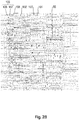
Figure 2A shows a perspective front view of the outdoor unit offigure 1 ; -
Figure 2B shows an enlarged perspective view of a portion offigure 2A ; -
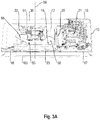
Figure 3A shows a perspective top view of the outdoor unit offigure 1 with the top plate of the casing being removed; -
Figure 3B shows a perspective top view of the outdoor unit offigure 1 with the top plate and the bell mouth of the casing being removed; -
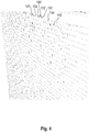
Figure 4 shows an enlarged perspective view of the grille of the outdoor unit infigure 1 ; -
Figure 5 shows a rearview of the grille of the outdoor unit infigure 1 ; -
Figure 6 front view of another outdoor unit in accordance with the present disclosure; and -
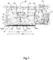
Figure 7 shows a cross-section along a horizontal plane 7-7 of the outdoor unit infigure 6 , wherein some parts have been omitted. - An embodiment will now be explained with reference to the drawings. It will be apparent to those skilled in the field of heat pumps from this disclosure that the following description of the embodiment is provided for illustration only and not for the purpose of limiting the invention as defined by the appended claims. In addition the same or similar reference numerals are used when describing different examples of the present disclosure and a repetitive description is omitted.
-
Figure 1 shows a perspective view of anoutdoor unit 10 of a split type heat pump. The heat pump comprises a refrigerant circuit, at least comprising a heatsource heat exchanger 30, a compressor (not visible), a heat consumer heat exchanger (not shown), such as an indoor heat exchanger, and an expansion valve connected by refrigerant pipes. - The shown
outdoor unit 10 comprises acasing 11. Thecasing 11 has abottom plate 12. Feet 13 (seefigure 2A ) for mounting the outdoor unit on a horizontal surface or via brackets to a vertical wall are fixed to thebottom plate 12. Further, thecasing 11 has atop plate 14 and aside plate 15. In the shown embodiment, theside plate 15 extends around a rearward corner of theoutdoor unit 10 being connected to (integrally formed with/forming a one piece structure with) aback plate 16 of thecasing 11. - As will be best visible from
figure 3A and3B , having thetop plate 14 removed, the heatsource heat exchanger 30 occupies a part of the rear side of thecasing 11 and the side of thecasing 11 opposite to theside plate 15. The heatsource heat exchanger 30 is "L" - shaped in a top view. - The front side of the
casing 11 is closed by afront plate 17 and abell mouth 18. Thefront plate 17 also extends around the forward corner of thecasing 11 forming part of the side of the casing 11.Thebell mouth 18 defines an air flow opening 19 (see alsofigure 2A ). In the shown embodiment, the air flow opening 19 is circular. - Further and as best visible in
figure 3A and3B , thecasing 11 is separated by apartition wall 20 into amachine chamber 21 and an air chamber 22 (heat exchanging area). In the shown configuration, the separation is in a horizontal direction, that is from the left to the right, wherein themachine chamber 21 is disposed on the right and theair chamber 22 is disposed on the left. - The
machine chamber 21 is, thus, formed by theback plate 16, theside plate 15, thefront plate 17 and thepartition wall 20. Theair chamber 22 is formed by the heatsource heat exchanger 30, thebell mouth 18 and thepartition wall 20. - The
machine chamber 21 may accommodate components of the refrigerant circuit such as the compressor and the expansion valve and/or portions of the control of the heat pump. In addition, the heatsource heat exchanger 30 may at one end extend into themachine chamber 21 so as to connect refrigerant pipes of the heatsource heat exchanger 30 to the remainder of the refrigerant circuit. - The
casing 11 further accommodates afan 50. Thefan 50 is accommodated in theair chamber 22. More particularly, thefan 50 is supported on thebottom plate 12 via a support structure 51. A fan motor 52 is mounted to the support structure 51. Thefan 50 further comprises afan rotor 53 having afan hub 54 mounted to the fan motor 52. A plurality of fan blades 55 (in the present embodiment three) extend radially outwardly from thefan hub 54. Thefan rotor 53 and, hence, thefan blades 55 are rotatable about an axis ofrotation 56 by the fan motor 52. - The
fan 50 is mounted with the axis ofrotation 56 concentric to the air flow opening 19 of thebell mouth 18. Even further and as apparent fromfigure 3A , thebell mouth 18 has anannular rim 23 at the circumference of theair flow opening 19. Thefan blades 55 partly enter therim 23 of thebell mouth 18. - A
grille 100 is, as a fan guard, attached to thecasing 11 opposite to theback plate 16/a back side of thecasing 11 at a front side of thecasing 11. In particular, thegrille 100 is mounted to thebell mouth 18 and thefront plate 17. One purpose of thegrille 100 is to meet e.g. the standard EN 60335-1:2012, relating to finger safety, that is to prevent that a finger comes into contact with thefan blades 55 of thefan 50 and consequently to avoid injuries. - In the shown embodiment, an
outer surface 101 of thegrille 100 is outwardly curved (see top view infigure 3A and3B ). As a result, the distance D (minimum distance) between thefan blades 55 and theouter surface 101 of thegrille 100 differs at different locations of theouter surface 101. In particular, the distance D differs along the horizontal direction (from the left to the right) in which theouter surface 101 is curved. - The distance D between the
fan blades 55 and theouter surface 101, particularly the minimum distance is indicated infigure 3B . In particular, the distance D is defined as the distance of that point on thefan blades 55, which is closest to theouter surface 101 of thegrille 100, to theouter surface 101 of thegrille 100. Also visible fromfigure 3B is that the maximum distance DMax is offset relative to the axis ofrotation 56 to the right and, hence, situated in the area A2 (see later). - Finger safety according to the standard EN 60335-1:2012 may, on the one hand, be achieved by defining a sufficiently large safety distance between the
outer surface 101 of thegrille 100 and thefan blades 55. - Referring to
figure 2A , thegrille 100 is divided into afan portion 110 covering thefan 50 or more particularly thebell mouth 18 and amachine chamber portion 111 covering a portion of thecasing 10 defining themachine chamber 21. - As shown in
figure 2A and2B as well asfigure 4 , thegrille 100 comprises, in thefan portion 110, at least in the area of the air flow opening 19, a plurality ofopenings 102. Theopenings 102 allow air to flow through thegrille 100 and, hence, through the heatsource heat exchanger 30. Thus, the size of theopenings 102 influences the flow resistance of the air flow through thegrille 100. However, depending on the safety distance between theouter surface 101 of thegrille 100 and thefan blades 55, the smallest dimension of theopenings 102 is additionally limited by the standard EN 60335-1:2012 relating to finger safety. - In the particular embodiment, the
outer surface 101 is particularly defined by afront edge 103 of a plurality of parallel horizontal ribs 104 (first horizontal ribs). Thehorizontal ribs 104 are equally distanced to each other and extend over the entire front of thegrille 100. Hence, one may consider thefront edges 103 of thehorizontal ribs 104 to be outwardly curved relative to a plane defined by the most forward point on each of thefan blades 55. - The
openings 102 are formed by a plurality of vertical ribs 105 (second vertical ribs) extending between two adjacenthorizontal ribs 104. Thevertical ribs 105 also extend substantially parallel to each other. In this context "substantially" means that due to the curvature, a slight deviation from the parallel orientation between thevertical ribs 105 may occur. In particular, if afront edge 106 of thevertical ribs 105 is always oriented parallel to thefront edge 103 of thehorizontal ribs 104, thevertical ribs 105 will not be perfectly parallel to each other. - The
vertical ribs 105 comprisesmaller ribs 107 and thelarger ribs 108. Thesmaller ribs 107 have a smaller depth in the direction of or parallel to the direction of the axis ofrotation 56 than thelarger ribs 108. Thus, thefront edge 106 of thesmaller ribs 107 is displaced towards the back with respect to thefront edges 106 of thelarger ribs 108 relative to thefront edge 103 of thehorizontal ribs 104. As a consequence, in some viewing angles (seefigure 4 ) thesmaller ribs 107 are not visible, enhancing the entire outer appearance of thegrille 100 and, therefore, theoutdoor unit 10. - In addition, as will be best visible from
figures 2B and4 , thelarger ribs 108 are in a vertical direction not aligned. Rather,larger ribs 108 in adjacent rows in a vertical direction are offset to each other in the horizontal direction. Thus, any strict geometric arrangement of the ribs is diluted and the outer appearance is enhanced. - In addition and as will be apparent from particularly
figures 2A and2B , the distances between adjacentsmaller ribs 107 are different over the entire front of thegrille 100. In one example, the distances betweensmaller ribs 107 between two adjacentlarger ribs 108 in the horizontal direction may be the same. - To the contrary, the distances between adjacent
larger ribs 108 may be the same over the entire front of thegrille 100. As thesmaller ribs 107 are under certain angles not visible as mentioned above, the outer appearance is, hence, dominated by thelarger ribs 18. Again this has an influence on and improves the outer appearance of theoutdoor unit 10. - Generally, two requirements may be used to comply with the standard EN 60335-1:2012 for mechanical finger safety. One requirement is the (minimum) safety distance D between the
fan blades 55 and theouter surface 101 of thegrille 101. The other requirement is the maximum allowable size (smallest dimension) of the openings of the grille. In regard of the latter, the smallest dimension of each of the openings is relevant. - In the present embodiment, the openings are defined by the
horizontal ribs 104 and thevertical ribs 105 and are rectangular, particularly slot shaped. The smallest dimension of theopenings 102 in regard of finger safety is in the present example defined by the distance between adjacentvertical ribs 105. - In order to test whether the outdoor unit complies with said standard, test probes as defined in IEC 61032 are used. In particular, a test probe B as defined in IEC 61032, as normal finger test probe (resembling fingers as of the age of 14 and older), and a
test probe 18 as defined in IEC 61032, as small finger test probe (resembling fingers as of the age of 3 until the age of 14), are used. In the test, which is defined in the standard EN 60335-1:2012, the test probe is pressed against the grille with a force of 5N for the normal finger probe and 2.5N for the small finger probe. - Further, in the present example, the
outer surface 101 of thegrille 100 is curved so that the distance D between thefan blades 55 and theouter surface 101 of thegrille 100 differs. - Accordingly, in the present embodiment, the
grille 100 has in itsfan portion 110 two areas A1 and A2. In the present example, the areas A1 and A2 are separated by a vertical line which may be centered on the axis ofrotation 56 of the fan 50 (seefigure 2A ). - In the area A2, the distance D is larger than a first threshold, wherein the first threshold represents the required safety distance for both a first group of humans, such as humans from the age of 3 to 14 (children) and a second group of humans, such as humans from the age of 14 and older (adults). Thus, the first threshold may be 80.0 mm (±0.2mm tolerance).
- Thus, in the area A2, the size of the openings may be "freely" selected as regards the smallest dimension at a minimum safety distance of the first threshold. Thus, the distance between the
vertical ribs 105 is not of high relevance in the area A2 and may be larger. - To the contrary, in the area A1, the distance D is not more than the first threshold, but may be selected to be larger than a third threshold. The third threshold represents the required safety distance for humans from the age of 3 to 14 (children). Thus, the third threshold may be 57.9mm (±0.15mm tolerance).
- In this case, however, the safety distance D in the area A1 is not sufficient for humans from the age of 14 and older (adults). Accordingly, the smallest dimension of the
openings 102 must be reduced to meet the standard for finger safety. - In the present example the smallest dimension of the
openings 102, even though the smallest dimension may be different betweendifferent openings 102 in the area A1, is selected to be not more than a second threshold. The second threshold represents the maximum allowable smallest dimension for openings if the safety distance for humans from the age of 14 and older (adults) is not met or not more than the first threshold. Thus, the second threshold may be 12mm +0/-0.05. - Accordingly, in the area A1, the finger safety for both children and adults is achieved by both the distance D (for children) and the smallest dimension of the openings 102 (for adults).
- In the area A2, the finger safety for both children and adults is achieved by mainly the distance D.
- As indicated above, the distance between the
vertical ribs 105 differs between the area A1 and the area A2. In order not to have an abrupt change of the distance between adjacentvertical ribs 105 from the first area A1 to the second area A2, the distance between adjacent vertical ribs gradually changes (increases) at least in the first area A1 towards the second area A2. Yet, according to another embodiment, the distance between adjacentvertical ribs 105 may gradually increase over theentire fan portion 110 in the horizontal direction from the first area A1 to the second area A2, that is from the left to the right in the present embodiment. In this context, "gradually increase" does not necessarily mean that the distance between each and every adjacentvertical ribs 105 needs to change. As previously mentioned, the distance betweensmaller ribs 107 arranged between two adjacentlarger ribs 108 may be the same. Thus, "gradually" also encompasses that the distance between the vertical ribs changes in groups. - As can be seen from
figure 2A andfigure 5 , thegrille 100 has in its machine chamber portion 111 aclosed surface 112 withoutopenings 10 and 2. However, thehorizontal ribs 104 also extend into and over themachine chamber portion 111. - In addition, the
grille 100 has ahub portion 109 corresponding to thefan hub 54 in which no orless openings 102 are provided. - Moreover,
figure 5 represents that thegrille 100 in the example consists of afirst part 113 and asecond part 114. This particularly simplifies the molding process of thegrille 100. Theparts casing 10. In addition, theparts parts parts parts grille 100. In particular, during the finger test as mentioned above, a force is applied when pressing the finger into theopenings 102. Thegrille 100 needs to withstand at least those forces. - As explained earlier, the
grille 100 extends over the entire front side of the casing and therefore resembles or represents a front panel of theoutdoor unit 10. As a regular maintenance of the outdoor unit, particularly of components within themachine chamber 21, is required, theoutdoor unit 10 needs to be configured to allow access to themachine chamber 21. However, it may be cumbersome to each and every time detach theentire grille 100. Thus, in order to enhance serviceability, at least the back plate 16 (in the present example theback plate 16 and the side plate 15) is detachable so as to give access to themachine chamber 21. - In addition, the two areas do not necessarily have to be arranged side-by-side and be separated by a straight vertical line as in the example described above. Rather, the areas can also be separated by non-straight lines or be defined by concentric circles. Such an example is explained with respect to
figures 6 and7 . In the following, only the difference to the above example will be explained. Regarding features which are the same or similar, reference is made to the above description in order to avoid repetition. - The
grille 1000 shown infigures 6 and7 is arranged on thecasing 11 only in afan portion 1110 corresponding to theair chamber 22 and does not extend into themachine chamber portion 1111 corresponding to themachine chamber 21. - In addition, and as best visible from
figure 7 , theouter surface 1101 defined by thefront edges 1103 of the annular 1115 ribs and the radial ribs 1116 is in a top view flat. To put it differently, theouter surface 1101 extends perpendicularly to the axis ofrotation 56 of thefan blades 55. Thus, theouter surface 1101 extends vertically. - Yet, the
fan blades 55 are shaped so that the distance of the most forward edge of thefan blades 55 facing thegrille 1000 differs in a radial direction. In this context, the minimum distance DMin between theouter surface 1101 and the most forward edge of thefan blades 55 resides towards a radially outer circumference of thefan blades 55, whereas the maximum distance DMax is located towards a radially inner circumference close to thefan hub 54. - As a result and different to the above example, the change in distance is realized by the shape of the
fan blades 55 rather than the curvature of theouter surface 101 of thegrille 100. Yet, both aspects may certainly be combined. - As the
fan blades 55 are rotating, the areas A1 and A2 are in the present example defined by concentric rings having the diameter ØA1 and ØA2. The concentric rings are centered on the axis ofrotation 56 of thefan blades 55. To be more particular, the first area A1 is defined between the outer ring having the diameter ØA1 and the inner ring having the diameter ØA2. The second area A2 is defined by the inner ring having the diameter ØA2 and includes the hub portion 1109. - As visible from
figure 7 , the first area A1 comprises the minimum distance DMin whereas the second area A2 comprises the maximum distance DMax. - Moreover, the
grille 1000 comprises a plurality ofopenings 1102 for allowing air to pass thegrille 1000. Theopenings 1102 are formed by a plurality ofannular ribs 1115 intersecting with a plurality of radial ribs 116. The smallest dimension of theopenings 1102 is in this example defined by the distance between adjacentannular ribs 1115. As will be apparent from the front view infigure 6 , the distance between theannular ribs 1115 is larger in the second area A2, in which the distance D of theouter surface 1101 to thefan blades 55 is larger than in the first area A1, in which the distance D of theouter surface 1101 to thefan blades 55 is smaller. Thus, a similar concept as with respect to the above example is realized, but with the areas being defined by concentric circles as explained above. - As previously mentioned, both concepts may be combined and also other features of the first example which have not explicitly been described with respect to the present example may be embodied such as ribs having a different depth, offsetting of ribs and a radial increase decrease of the smallest dimension from one area to the other.
- Further, it is to be understood that the present description of an embodiment is not considered to be limiting. Rather several modifications may be realized by the skilled person. For example, more than the two areas A1 and A2 may be defined.
- Further, the
outer surface 101 of thegrille 100 is curved in only one direction, namely the horizontal direction. It may be curved in a different direction such as the vertical direction and it may be curved in more than one direction such as in the horizontal and the vertical direction. - Furthermore, the present description has been made in view of the standard EN 60335-1:2012for finger safety. In different countries, different standards may apply so that the thresholds given above may differ from country to country. Thus, the present disclosure is to be understood in that the thresholds are distinguished between a first group and a second group of humans as indicated above and not necessarily limited to the groups as defined above and given in EN 60335-1:2012.
-
- 10
- outdoor unit
- 11
- casing
- 12
- bottom plate
- 13
- feet
- 14
- top plate
- 15
- side plate
- 16
- back plate
- 17
- front plate
- 18
- bell mouth
- 19
- air flow opening
- 20
- partition wall
- 21
- machine chamber
- 22
- air chamber
- 23
- rim
- 30
- heat source heat exchanger
- 50
- fan
- 51
- support structure
- 52
- fan motor
- 53
- fan rotor
- 54
- fan hub
- 55
- fan blade
- 56
- axis of rotation
- 100, 1000
- grille
- 101, 1101
- outer surface
- 102, 1102
- opening
- 103, 1103
- front edge
- 104
- horizontal rib
- 105
- vertical rib
- 106
- front edge
- 107
- smaller rib
- 108
- larger rib
- 109, 1109
- hub portion
- 110, 1110
- fan portion
- 111, 1111
- machine chamber portion
- 112
- closed surface
- 113
- first part
- 114
- second part
- 1115
- annular ribs
- 1116
- radial ribs
Claims (15)
- Outdoor unit (10) for a heat pump comprising a refrigerant circuit, the outdoor unit (10) comprising:a casing (11),a fan (50) accommodated in the casing, the fan (50) having fan blades (55) rotatable about an axis of rotation (56),a grille (100) covering the fan blades (55), characterized in thatthe grille (100; 1000) is divided into a first area (A1) and a second area (A2),
the first area (A1) being defined so that the distance (D) between the fan blades (55) and an outer surface (101; 1101) of the grille (100; 1100) is not more than a first threshold, and
the second area (A2) being defined so that the distance (D) between the fan blades (55) and the outer surface (101; 1101) of the grille (100; 1100) is larger than the first threshold,
wherein openings (102; 1102) are formed in the first (A1) and second (A2) areas of the grille (100; 1100), a smallest dimension of each of the openings (102; 1102) in the first area (A1) perpendicular to the axis of rotation (56) of the fan blades (55) is not more than a second threshold and a smallest dimension of at least some of the openings (102) in the second area (A2) perpendicular to the axis of rotation (56) of the fan blades (55) is larger than the second threshold. - Outdoor unit according to claim 1, wherein the outer surface (101) of the grille (100) is outwardly curved, preferably outwardly curved at least in a horizontal curvature direction.
- Outdoor unit according to claim 2, wherein the position of a maximum distance (DMax) of the outer surface (101) to the fan blades (55) is offset relative to the axis of rotation (56) in the horizontal curvature direction.
- Outdoor unit according to claim 3, wherein the second area (A2) comprises the maximum distance (DMax) between the fan blades (55) and the outer surface (101) of the grille (100).
- Outdoor unit according to claim 1, wherein the outer surface (1101) of the grille (1100) is flat.
- Outdoor unit according to any one of the preceding claims, wherein at least the smallest dimensions of the openings (102; 1102) at least in the first area (A1) gradually increase towards the second area (A2).
- Outdoor unit according to any one of the preceding claims, wherein the second threshold is 12.0mm +0/-0.05mm.
- Outdoor unit according to any one of the preceding claims, wherein the first threshold is 80.0mm ±0.2mm.
- Outdoor unit according to any one of the preceding claims, wherein the distance (D) of the outer surface (101; 1101) of the grille (100; 1100) to the fan blades (55) in the first area (A1) is not smaller than a third threshold, the third threshold is 57.9mm ±0.15mm.
- Outdoor unit according to any one of the preceding claims, wherein the casing (11) is in a view perpendicular to the grille (100) separated into a machine chamber (21) and a heat exchanging area (22), the heat exchanging area comprising the fan (50) and the machine chamber (21) comprising components of the refrigerant circuit of the heat pump, wherein the grille (100) has a portion (111) having a closed surface (112), the portion (111) corresponding to the portion of the machine chamber (21).
- Outdoor unit according to any one of the preceding claims, wherein the openings (102) are formed by first horizontal ribs (104) and second vertical ribs (105) extending perpendicular to the first horizontal ribs (104).
- Outdoor unit according to claim 11, wherein the second vertical ribs (105) comprise smaller ribs (107) and larger ribs (108), the smaller ribs (107) being smaller in depth in the direction parallel to the axis of rotation (56) of the fan blades (55) than the larger ribs (108).
- Outdoor unit according to claim 12, wherein the larger ribs (108) in adjacent rows of second vertical ribs (105) in a vertical direction are offset to each other in the horizontal direction.
- Outdoor unit according to any one of the preceding claims, wherein the grille (100; 1100) is arranged on a front side of the casing (11) and the casing (11) has a back plate (16) on a side opposite to the front side, the back plate (16) being detachable for giving access to components of the refrigerant circuit of the heat pump accommodated in the casing (11).
- Outdoor unit according to any one of the preceding claims, wherein the first and second area (A1, A2) are defined on respective opposite sides of a line, particularly a vertical line on the outer surface (101) of the grille (100) or by concentric rings on the outer surface (1101) of the grille (1100).
Priority Applications (2)
| Application Number | Priority Date | Filing Date | Title |
|---|---|---|---|
| EP19161605.1A EP3705732B1 (en) | 2019-03-08 | 2019-03-08 | Outdoor unit for a heat pump having a grille |
| PCT/JP2020/009891 WO2020184494A1 (en) | 2019-03-08 | 2020-03-06 | Outdoor unit for a heat pump having a grille with openings of differents dimensions |
Applications Claiming Priority (1)
| Application Number | Priority Date | Filing Date | Title |
|---|---|---|---|
| EP19161605.1A EP3705732B1 (en) | 2019-03-08 | 2019-03-08 | Outdoor unit for a heat pump having a grille |
Publications (2)
| Publication Number | Publication Date |
|---|---|
| EP3705732A1 true EP3705732A1 (en) | 2020-09-09 |
| EP3705732B1 EP3705732B1 (en) | 2023-08-09 |
Family
ID=65729209
Family Applications (1)
| Application Number | Title | Priority Date | Filing Date |
|---|---|---|---|
| EP19161605.1A Active EP3705732B1 (en) | 2019-03-08 | 2019-03-08 | Outdoor unit for a heat pump having a grille |
Country Status (2)
| Country | Link |
|---|---|
| EP (1) | EP3705732B1 (en) |
| WO (1) | WO2020184494A1 (en) |
Cited By (4)
| Publication number | Priority date | Publication date | Assignee | Title |
|---|---|---|---|---|
| FR3119882A1 (en) | 2021-02-16 | 2022-08-19 | Pierrick MAILHET | Air conditioning outdoor unit |
| EP4425057A1 (en) | 2023-03-03 | 2024-09-04 | Daikin Europe N.V. | Heat source unit of a heat pump |
| EP4425000A1 (en) | 2023-03-03 | 2024-09-04 | Daikin Europe N.V. | Heat source unit of an air heat pump |
| WO2026043368A1 (en) * | 2024-08-21 | 2026-02-26 | Whspr B.V. | Noise-reducing design of an external unit of a heat transfer device |
Citations (5)
| Publication number | Priority date | Publication date | Assignee | Title |
|---|---|---|---|---|
| JPS5733339Y2 (en) * | 1977-07-08 | 1982-07-22 | ||
| JPH08247097A (en) * | 1995-03-09 | 1996-09-24 | Toshiba Ave Corp | Fan guard |
| JP2010060217A (en) * | 2008-09-04 | 2010-03-18 | Toshiba Carrier Corp | Heat source unit |
| FR3013807A1 (en) * | 2013-11-28 | 2015-05-29 | Air Liquide | VENTILATION DEVICE FOR REFRIGERATING EXCHANGER WITH DEPORTED PROTECTION GRID |
| EP3348842A1 (en) | 2015-09-08 | 2018-07-18 | Mitsubishi Electric Corporation | Propeller fan, propeller fan device and outdoor unit for air conditioning device |
Family Cites Families (4)
| Publication number | Priority date | Publication date | Assignee | Title |
|---|---|---|---|---|
| JPH06137608A (en) * | 1992-10-28 | 1994-05-20 | Toshiba Ave Corp | Outdoor unit for air conditioner |
| JP2003176934A (en) * | 2001-12-12 | 2003-06-27 | Chofu Seisakusho Co Ltd | Air outlet grill for outdoor unit of air conditioner |
| JP6524243B2 (en) * | 2015-09-07 | 2019-06-05 | 三菱電機株式会社 | Outdoor unit of air conditioner |
| EP3798524B1 (en) * | 2018-05-22 | 2023-12-20 | Mitsubishi Electric Corporation | Air blowing device and air conditioner |
-
2019
- 2019-03-08 EP EP19161605.1A patent/EP3705732B1/en active Active
-
2020
- 2020-03-06 WO PCT/JP2020/009891 patent/WO2020184494A1/en not_active Ceased
Patent Citations (5)
| Publication number | Priority date | Publication date | Assignee | Title |
|---|---|---|---|---|
| JPS5733339Y2 (en) * | 1977-07-08 | 1982-07-22 | ||
| JPH08247097A (en) * | 1995-03-09 | 1996-09-24 | Toshiba Ave Corp | Fan guard |
| JP2010060217A (en) * | 2008-09-04 | 2010-03-18 | Toshiba Carrier Corp | Heat source unit |
| FR3013807A1 (en) * | 2013-11-28 | 2015-05-29 | Air Liquide | VENTILATION DEVICE FOR REFRIGERATING EXCHANGER WITH DEPORTED PROTECTION GRID |
| EP3348842A1 (en) | 2015-09-08 | 2018-07-18 | Mitsubishi Electric Corporation | Propeller fan, propeller fan device and outdoor unit for air conditioning device |
Cited By (6)
| Publication number | Priority date | Publication date | Assignee | Title |
|---|---|---|---|---|
| FR3119882A1 (en) | 2021-02-16 | 2022-08-19 | Pierrick MAILHET | Air conditioning outdoor unit |
| EP4425057A1 (en) | 2023-03-03 | 2024-09-04 | Daikin Europe N.V. | Heat source unit of a heat pump |
| EP4425000A1 (en) | 2023-03-03 | 2024-09-04 | Daikin Europe N.V. | Heat source unit of an air heat pump |
| WO2024184247A1 (en) | 2023-03-03 | 2024-09-12 | Daikin Europe N.V. | Heat source unit of a heat pump |
| WO2024184245A1 (en) | 2023-03-03 | 2024-09-12 | Daikin Europe N.V. | Heat source unit of an air heat pump |
| WO2026043368A1 (en) * | 2024-08-21 | 2026-02-26 | Whspr B.V. | Noise-reducing design of an external unit of a heat transfer device |
Also Published As
| Publication number | Publication date |
|---|---|
| EP3705732B1 (en) | 2023-08-09 |
| WO2020184494A1 (en) | 2020-09-17 |
Similar Documents
| Publication | Publication Date | Title |
|---|---|---|
| WO2020184494A1 (en) | Outdoor unit for a heat pump having a grille with openings of differents dimensions | |
| EP1357337B1 (en) | Fan guard of fan unit | |
| EP2698543B1 (en) | Centrifugal fan and air conditioner | |
| EP2461042B1 (en) | Air blower for an air conditioner | |
| AU2003284610B2 (en) | Centrifugal fan, and air conditioner provided therewith | |
| US10024332B2 (en) | Centrifugal fan and air conditioner provided with the same | |
| CN106016453B (en) | Ceiling embedded air conditioner | |
| EP3141762B1 (en) | Axial flow fan with unevenly distributed blades and with a balancing protrusion moulded in the hub | |
| EP2799719B1 (en) | Axial flow fan | |
| CN204025148U (en) | Centrifugal fan | |
| EP3705731B1 (en) | Outdoor unit for a heat pump having a grille made of separate parts | |
| AU2014238673A1 (en) | Centrifugal fan and air conditioner having the same | |
| EP2792886B1 (en) | Turbofan | |
| EP3321597B1 (en) | Indoor unit for air conditioner | |
| EP1610068B1 (en) | Outdoor unit for air conditioner | |
| JPH0396700A (en) | Air blower | |
| EP2920521B1 (en) | Indoor device for an air conditioner | |
| KR200462303Y1 (en) | Outdoor unit for air conditioner | |
| JP5195983B2 (en) | Centrifugal blower | |
| JP7702667B2 (en) | Turbofan | |
| CN217057904U (en) | Air inlet cover, fresh air device and air conditioner | |
| CN219166206U (en) | Air fryer | |
| US8061985B2 (en) | Ceiling-embedded ventilation fan | |
| CN112413870B (en) | Air conditioner baffle subassembly and have its air conditioner | |
| JPH0243016Y2 (en) |
Legal Events
| Date | Code | Title | Description |
|---|---|---|---|
| PUAI | Public reference made under article 153(3) epc to a published international application that has entered the european phase |
Free format text: ORIGINAL CODE: 0009012 |
|
| STAA | Information on the status of an ep patent application or granted ep patent |
Free format text: STATUS: REQUEST FOR EXAMINATION WAS MADE |
|
| 17P | Request for examination filed |
Effective date: 20200302 |
|
| AK | Designated contracting states |
Kind code of ref document: A1 Designated state(s): AL AT BE BG CH CY CZ DE DK EE ES FI FR GB GR HR HU IE IS IT LI LT LU LV MC MK MT NL NO PL PT RO RS SE SI SK SM TR |
|
| AX | Request for extension of the european patent |
Extension state: BA ME |
|
| STAA | Information on the status of an ep patent application or granted ep patent |
Free format text: STATUS: EXAMINATION IS IN PROGRESS |
|
| 17Q | First examination report despatched |
Effective date: 20211217 |
|
| RAP3 | Party data changed (applicant data changed or rights of an application transferred) |
Owner name: DAIKIN EUROPE N.V. Owner name: DAIKIN INDUSTRIES, LTD. |
|
| GRAP | Despatch of communication of intention to grant a patent |
Free format text: ORIGINAL CODE: EPIDOSNIGR1 |
|
| STAA | Information on the status of an ep patent application or granted ep patent |
Free format text: STATUS: GRANT OF PATENT IS INTENDED |
|
| INTG | Intention to grant announced |
Effective date: 20230330 |
|
| GRAS | Grant fee paid |
Free format text: ORIGINAL CODE: EPIDOSNIGR3 |
|
| GRAA | (expected) grant |
Free format text: ORIGINAL CODE: 0009210 |
|
| STAA | Information on the status of an ep patent application or granted ep patent |
Free format text: STATUS: THE PATENT HAS BEEN GRANTED |
|
| P01 | Opt-out of the competence of the unified patent court (upc) registered |
Effective date: 20230530 |
|
| AK | Designated contracting states |
Kind code of ref document: B1 Designated state(s): AL AT BE BG CH CY CZ DE DK EE ES FI FR GB GR HR HU IE IS IT LI LT LU LV MC MK MT NL NO PL PT RO RS SE SI SK SM TR |
|
| REG | Reference to a national code |
Ref country code: GB Ref legal event code: FG4D |
|
| REG | Reference to a national code |
Ref country code: CH Ref legal event code: EP |
|
| REG | Reference to a national code |
Ref country code: IE Ref legal event code: FG4D |
|
| REG | Reference to a national code |
Ref country code: DE Ref legal event code: R096 Ref document number: 602019034381 Country of ref document: DE |
|
| REG | Reference to a national code |
Ref country code: LT Ref legal event code: MG9D |
|
| REG | Reference to a national code |
Ref country code: NL Ref legal event code: MP Effective date: 20230809 |
|
| REG | Reference to a national code |
Ref country code: AT Ref legal event code: MK05 Ref document number: 1597810 Country of ref document: AT Kind code of ref document: T Effective date: 20230809 |
|
| PG25 | Lapsed in a contracting state [announced via postgrant information from national office to epo] |
Ref country code: GR Free format text: LAPSE BECAUSE OF FAILURE TO SUBMIT A TRANSLATION OF THE DESCRIPTION OR TO PAY THE FEE WITHIN THE PRESCRIBED TIME-LIMIT Effective date: 20231110 |
|
| PG25 | Lapsed in a contracting state [announced via postgrant information from national office to epo] |
Ref country code: IS Free format text: LAPSE BECAUSE OF FAILURE TO SUBMIT A TRANSLATION OF THE DESCRIPTION OR TO PAY THE FEE WITHIN THE PRESCRIBED TIME-LIMIT Effective date: 20231209 |
|
| PG25 | Lapsed in a contracting state [announced via postgrant information from national office to epo] |
Ref country code: SE Free format text: LAPSE BECAUSE OF FAILURE TO SUBMIT A TRANSLATION OF THE DESCRIPTION OR TO PAY THE FEE WITHIN THE PRESCRIBED TIME-LIMIT Effective date: 20230809 Ref country code: RS Free format text: LAPSE BECAUSE OF FAILURE TO SUBMIT A TRANSLATION OF THE DESCRIPTION OR TO PAY THE FEE WITHIN THE PRESCRIBED TIME-LIMIT Effective date: 20230809 Ref country code: PT Free format text: LAPSE BECAUSE OF FAILURE TO SUBMIT A TRANSLATION OF THE DESCRIPTION OR TO PAY THE FEE WITHIN THE PRESCRIBED TIME-LIMIT Effective date: 20231211 Ref country code: NO Free format text: LAPSE BECAUSE OF FAILURE TO SUBMIT A TRANSLATION OF THE DESCRIPTION OR TO PAY THE FEE WITHIN THE PRESCRIBED TIME-LIMIT Effective date: 20231109 Ref country code: NL Free format text: LAPSE BECAUSE OF FAILURE TO SUBMIT A TRANSLATION OF THE DESCRIPTION OR TO PAY THE FEE WITHIN THE PRESCRIBED TIME-LIMIT Effective date: 20230809 Ref country code: LV Free format text: LAPSE BECAUSE OF FAILURE TO SUBMIT A TRANSLATION OF THE DESCRIPTION OR TO PAY THE FEE WITHIN THE PRESCRIBED TIME-LIMIT Effective date: 20230809 Ref country code: LT Free format text: LAPSE BECAUSE OF FAILURE TO SUBMIT A TRANSLATION OF THE DESCRIPTION OR TO PAY THE FEE WITHIN THE PRESCRIBED TIME-LIMIT Effective date: 20230809 Ref country code: IS Free format text: LAPSE BECAUSE OF FAILURE TO SUBMIT A TRANSLATION OF THE DESCRIPTION OR TO PAY THE FEE WITHIN THE PRESCRIBED TIME-LIMIT Effective date: 20231209 Ref country code: HR Free format text: LAPSE BECAUSE OF FAILURE TO SUBMIT A TRANSLATION OF THE DESCRIPTION OR TO PAY THE FEE WITHIN THE PRESCRIBED TIME-LIMIT Effective date: 20230809 Ref country code: GR Free format text: LAPSE BECAUSE OF FAILURE TO SUBMIT A TRANSLATION OF THE DESCRIPTION OR TO PAY THE FEE WITHIN THE PRESCRIBED TIME-LIMIT Effective date: 20231110 Ref country code: FI Free format text: LAPSE BECAUSE OF FAILURE TO SUBMIT A TRANSLATION OF THE DESCRIPTION OR TO PAY THE FEE WITHIN THE PRESCRIBED TIME-LIMIT Effective date: 20230809 Ref country code: AT Free format text: LAPSE BECAUSE OF FAILURE TO SUBMIT A TRANSLATION OF THE DESCRIPTION OR TO PAY THE FEE WITHIN THE PRESCRIBED TIME-LIMIT Effective date: 20230809 |
|
| PG25 | Lapsed in a contracting state [announced via postgrant information from national office to epo] |
Ref country code: PL Free format text: LAPSE BECAUSE OF FAILURE TO SUBMIT A TRANSLATION OF THE DESCRIPTION OR TO PAY THE FEE WITHIN THE PRESCRIBED TIME-LIMIT Effective date: 20230809 |
|
| PG25 | Lapsed in a contracting state [announced via postgrant information from national office to epo] |
Ref country code: ES Free format text: LAPSE BECAUSE OF FAILURE TO SUBMIT A TRANSLATION OF THE DESCRIPTION OR TO PAY THE FEE WITHIN THE PRESCRIBED TIME-LIMIT Effective date: 20230809 |
|
| PG25 | Lapsed in a contracting state [announced via postgrant information from national office to epo] |
Ref country code: SM Free format text: LAPSE BECAUSE OF FAILURE TO SUBMIT A TRANSLATION OF THE DESCRIPTION OR TO PAY THE FEE WITHIN THE PRESCRIBED TIME-LIMIT Effective date: 20230809 Ref country code: RO Free format text: LAPSE BECAUSE OF FAILURE TO SUBMIT A TRANSLATION OF THE DESCRIPTION OR TO PAY THE FEE WITHIN THE PRESCRIBED TIME-LIMIT Effective date: 20230809 Ref country code: ES Free format text: LAPSE BECAUSE OF FAILURE TO SUBMIT A TRANSLATION OF THE DESCRIPTION OR TO PAY THE FEE WITHIN THE PRESCRIBED TIME-LIMIT Effective date: 20230809 Ref country code: EE Free format text: LAPSE BECAUSE OF FAILURE TO SUBMIT A TRANSLATION OF THE DESCRIPTION OR TO PAY THE FEE WITHIN THE PRESCRIBED TIME-LIMIT Effective date: 20230809 Ref country code: DK Free format text: LAPSE BECAUSE OF FAILURE TO SUBMIT A TRANSLATION OF THE DESCRIPTION OR TO PAY THE FEE WITHIN THE PRESCRIBED TIME-LIMIT Effective date: 20230809 Ref country code: CZ Free format text: LAPSE BECAUSE OF FAILURE TO SUBMIT A TRANSLATION OF THE DESCRIPTION OR TO PAY THE FEE WITHIN THE PRESCRIBED TIME-LIMIT Effective date: 20230809 Ref country code: SK Free format text: LAPSE BECAUSE OF FAILURE TO SUBMIT A TRANSLATION OF THE DESCRIPTION OR TO PAY THE FEE WITHIN THE PRESCRIBED TIME-LIMIT Effective date: 20230809 |
|
| REG | Reference to a national code |
Ref country code: DE Ref legal event code: R097 Ref document number: 602019034381 Country of ref document: DE |
|
| PLBE | No opposition filed within time limit |
Free format text: ORIGINAL CODE: 0009261 |
|
| STAA | Information on the status of an ep patent application or granted ep patent |
Free format text: STATUS: NO OPPOSITION FILED WITHIN TIME LIMIT |
|
| 26N | No opposition filed |
Effective date: 20240513 |
|
| PG25 | Lapsed in a contracting state [announced via postgrant information from national office to epo] |
Ref country code: SI Free format text: LAPSE BECAUSE OF FAILURE TO SUBMIT A TRANSLATION OF THE DESCRIPTION OR TO PAY THE FEE WITHIN THE PRESCRIBED TIME-LIMIT Effective date: 20230809 |
|
| REG | Reference to a national code |
Ref country code: CH Ref legal event code: PL |
|
| PG25 | Lapsed in a contracting state [announced via postgrant information from national office to epo] |
Ref country code: BG Free format text: LAPSE BECAUSE OF FAILURE TO SUBMIT A TRANSLATION OF THE DESCRIPTION OR TO PAY THE FEE WITHIN THE PRESCRIBED TIME-LIMIT Effective date: 20230809 |
|
| PG25 | Lapsed in a contracting state [announced via postgrant information from national office to epo] |
Ref country code: LU Free format text: LAPSE BECAUSE OF NON-PAYMENT OF DUE FEES Effective date: 20240308 |
|
| PG25 | Lapsed in a contracting state [announced via postgrant information from national office to epo] |
Ref country code: MC Free format text: LAPSE BECAUSE OF FAILURE TO SUBMIT A TRANSLATION OF THE DESCRIPTION OR TO PAY THE FEE WITHIN THE PRESCRIBED TIME-LIMIT Effective date: 20230809 |
|
| PG25 | Lapsed in a contracting state [announced via postgrant information from national office to epo] |
Ref country code: MC Free format text: LAPSE BECAUSE OF FAILURE TO SUBMIT A TRANSLATION OF THE DESCRIPTION OR TO PAY THE FEE WITHIN THE PRESCRIBED TIME-LIMIT Effective date: 20230809 Ref country code: LU Free format text: LAPSE BECAUSE OF NON-PAYMENT OF DUE FEES Effective date: 20240308 Ref country code: BG Free format text: LAPSE BECAUSE OF FAILURE TO SUBMIT A TRANSLATION OF THE DESCRIPTION OR TO PAY THE FEE WITHIN THE PRESCRIBED TIME-LIMIT Effective date: 20230809 |
|
| PG25 | Lapsed in a contracting state [announced via postgrant information from national office to epo] |
Ref country code: IE Free format text: LAPSE BECAUSE OF NON-PAYMENT OF DUE FEES Effective date: 20240308 |
|
| PG25 | Lapsed in a contracting state [announced via postgrant information from national office to epo] |
Ref country code: IE Free format text: LAPSE BECAUSE OF NON-PAYMENT OF DUE FEES Effective date: 20240308 Ref country code: CH Free format text: LAPSE BECAUSE OF NON-PAYMENT OF DUE FEES Effective date: 20240331 |
|
| PG25 | Lapsed in a contracting state [announced via postgrant information from national office to epo] |
Ref country code: CY Free format text: LAPSE BECAUSE OF FAILURE TO SUBMIT A TRANSLATION OF THE DESCRIPTION OR TO PAY THE FEE WITHIN THE PRESCRIBED TIME-LIMIT; INVALID AB INITIO Effective date: 20190308 |
|
| PG25 | Lapsed in a contracting state [announced via postgrant information from national office to epo] |
Ref country code: HU Free format text: LAPSE BECAUSE OF FAILURE TO SUBMIT A TRANSLATION OF THE DESCRIPTION OR TO PAY THE FEE WITHIN THE PRESCRIBED TIME-LIMIT; INVALID AB INITIO Effective date: 20190308 |
|
| PG25 | Lapsed in a contracting state [announced via postgrant information from national office to epo] |
Ref country code: TR Free format text: LAPSE BECAUSE OF FAILURE TO SUBMIT A TRANSLATION OF THE DESCRIPTION OR TO PAY THE FEE WITHIN THE PRESCRIBED TIME-LIMIT Effective date: 20230809 |
|
| PGFP | Annual fee paid to national office [announced via postgrant information from national office to epo] |
Ref country code: GB Payment date: 20260324 Year of fee payment: 8 |
|
| PGFP | Annual fee paid to national office [announced via postgrant information from national office to epo] |
Ref country code: DE Payment date: 20260319 Year of fee payment: 8 |
|
| PGFP | Annual fee paid to national office [announced via postgrant information from national office to epo] |
Ref country code: BE Payment date: 20260319 Year of fee payment: 8 Ref country code: IT Payment date: 20260324 Year of fee payment: 8 |
|
| PGFP | Annual fee paid to national office [announced via postgrant information from national office to epo] |
Ref country code: FR Payment date: 20260320 Year of fee payment: 8 |