EP4424901A1 - Accessory and garment steamer comprising the same - Google Patents
Accessory and garment steamer comprising the same Download PDFInfo
- Publication number
- EP4424901A1 EP4424901A1 EP23159198.3A EP23159198A EP4424901A1 EP 4424901 A1 EP4424901 A1 EP 4424901A1 EP 23159198 A EP23159198 A EP 23159198A EP 4424901 A1 EP4424901 A1 EP 4424901A1
- Authority
- EP
- European Patent Office
- Prior art keywords
- tray
- soleplate
- steamer
- garment
- steamer head
- Prior art date
- Legal status (The legal status is an assumption and is not a legal conclusion. Google has not performed a legal analysis and makes no representation as to the accuracy of the status listed.)
- Withdrawn
Links
Images



Classifications
-
- D—TEXTILES; PAPER
- D06—TREATMENT OF TEXTILES OR THE LIKE; LAUNDERING; FLEXIBLE MATERIALS NOT OTHERWISE PROVIDED FOR
- D06F—LAUNDERING, DRYING, IRONING, PRESSING OR FOLDING TEXTILE ARTICLES
- D06F79/00—Accessories for hand irons
- D06F79/02—Stands or supports neither attached to, nor forming part of, the iron or ironing board
-
- D—TEXTILES; PAPER
- D06—TREATMENT OF TEXTILES OR THE LIKE; LAUNDERING; FLEXIBLE MATERIALS NOT OTHERWISE PROVIDED FOR
- D06F—LAUNDERING, DRYING, IRONING, PRESSING OR FOLDING TEXTILE ARTICLES
- D06F73/00—Apparatus for smoothing or removing creases from garments or other textile articles by formers, cores, stretchers, or internal frames, with the application of heat or steam
-
- D—TEXTILES; PAPER
- D06—TREATMENT OF TEXTILES OR THE LIKE; LAUNDERING; FLEXIBLE MATERIALS NOT OTHERWISE PROVIDED FOR
- D06F—LAUNDERING, DRYING, IRONING, PRESSING OR FOLDING TEXTILE ARTICLES
- D06F75/00—Hand irons
- D06F75/08—Hand irons internally heated by electricity
- D06F75/10—Hand irons internally heated by electricity with means for supplying steam to the article being ironed
Definitions
- the invention relates to an accessory for use in a descaling operation of a garment steamer.
- the invention also relates to a garment steamer comprising the accessory.
- the invention may be used in the field of garment care.
- Garment steamers are known to be used for ironing or steaming garments to remove creases through the use of heat and moisture from steam.
- One type of garment steamer comprises a base unit, which base unit houses a water tank.
- a steamer head which can be alternatively referred to as an iron head or a handheld unit, is connected to the base unit by a flexible hose cord through which steam and/or water is delivered from the base unit to the steamer head.
- a steam generator is included in the base unit and/or the steamer head.
- the steamer head is provided with a soleplate, also known as a treatment plate, delimiting one or more steam vents through which steam is discharged onto a fabric being treated.
- a descaling operation/procedure tends to be recommended for such garment steamers in order to maintain efficient steam generation and to extend operating lifetime, particularly if relatively hard water is used.
- the descaling operation is usually conducted by the user holding the steamer head and allowing scale (together with hot water and/or steam) to be flushed out of the steamer head into the air or a sink. Holding the steamer head throughout the descaling operation tends to be necessary because of the risks, associated with hot water and steam discharge, to others, such as members of the user's family, and especially children.
- a descaling tray can be provided for receiving hot water, steam and/or scale discharged during the descaling operation.
- Potential safety issues associated with use of such a descaling tray can nonetheless arise.
- the steamer head can be dislodged from the descaling tray, together with the steamer head, can tip over during the descaling operation.
- hot water and/or steam discharged from the steamer head may not be received in the descaling tray, and/or any hot water already discharged into the descaling tray may spill out. The comfort and safety of the user, and anyone else in the vicinity, can therefore be compromised.
- the garment steamer may be designed for vertical steaming of hanging garments as well as horizontal ironing of garments lying on an ironing board. Such vertical steaming can necessitate a relatively small and lightweight steamer head. However, such a relatively small and lightweight steamer head can be susceptible to toppling over, particularly due to the hose cord having a weight that can equal or even exceed that of the steamer head. These factors can exacerbate the above-described safety issues associated with use of the descaling tray.
- the accessory according to the invention comprises a tray
- the attaching means which can be alternatively termed “an attachment system", can assist to reduce the risk of the steamer head, and the tip of the steamer head in particular, unintentionally separating from the tray during the descaling operation.
- the attaching means can assist to ensure safe implementing of the descaling operation.
- the lower portions of the tray By the lower portions of the tray backwardly protruding beyond the rear end of the soleplate when the soleplate is docked on the tray, the risk of backwards tipping of the tray, with the soleplate of the steamer head docked thereon, can be minimized.
- the lower portions in combination with the attaching means, can assist the steamer head to be supported on the tray, with the tray sitting stably on the external horizontal supporting surface, without the user being required to hold the steamer head.
- the plurality of supporting ribs comprises a pair of ribs that are spaced apart from each other across the back end of the tray.
- the pair of ribs can assist with balancing the tray on the external horizontal supporting surface.
- the plurality of supporting ribs comprises a central rib arranged between the pair of ribs.
- the central rib can add additional stability proximal to the back end of the tray.
- the optional central rib can assist to reinforce the stabilization provided by the pair of ribs.
- the central rib preferably backwardly protrudes by a shorter length than each of the pair of ribs.
- the tip of the steamer head that is attachable to the tray via the attaching means preferably comprises a tip of the steamer head's casing.
- Attaching the steamer head to the tray via its casing may provide a relatively robust and long-lasting solution, particularly in comparison to, for example, attaching the steamer head to the tray via a tip of the steamer head's soleplate due to the relatively high temperatures to which the soleplate is heated.
- the attaching means comprises a cavity for receiving the tip of the steamer head, e.g. the tip of the steamer head's casing. This may provide a relatively straightforwardly manufacturable way of implementing the attaching means.
- the cavity is preferably partly defined by an upper wall portion, with the upper wall portion being arranged to contact an upper surface of the tip of the steamer head when the soleplate is docked on the tray.
- the upper wall portion can assist to minimize the risk of tilting of the steamer head.
- the upper wall portion is arranged to contact an upwardly facing surface of the tip of the steamer head's casing when the soleplate is docked on the tray.
- the upper surface of the tray is arranged to support the soleplate at an angle relative to the lower surface of the tray. In other words, a first plane of the upper surface is angled with respect to a second plane of the lower surface.
- the tray can support the steamer head at a desired angle during the descaling process.
- Such an angle can, for instance, be selected to ensure that descaling solution is able to contact relevant parts of the interior of the steamer head during the descaling operation, in particular relevant parts at which scale is liable to build up.
- Such an angle can thus facilitate water and/or scale to be easily flushed-out from the interior of the steamer head.
- the tray comprises a recess (forming a recipient) for receiving scale and/or water from the steamer head during the descaling operation.
- a rim preferably extends at least partly around the recess, with the soleplate of the steamer head being supportable on the rim.
- the upper surface can be regarded as being included in the rim.
- the tray further comprises a flange extending at least partly around the recess.
- the flange can assist the user to manipulate the tray, for example when moving the tray containing water and/or scale.
- the flange can also assist with stowing of the tray after use, for example by assisting coupling of the tray to an ironing board.
- a garment steamer comprising a steamer head having a soleplate, and the accessory according to any of the embodiments described herein.
- the garment steamer comprises a hose cord arranged to backwardly extend away from a rear of the steamer head. Such backward extension of the hose cord can assist to minimize the risk of the hose cord impeding movement of the steamer head, in particular when the steamer head is being moved over a garment.
- a handle of the steamer head can backwardly extend beyond a rearmost portion of the steamer head's casing.
- the garment steamer comprises an ironing board, and coupling means adapted to detachably couple the tray to the ironing board when the soleplate is not being docked on the tray.
- the coupling means which can be alternatively termed “a coupling system", can assist the user to easily retrieve the tray when the descaling operation is due to be performed, noting that the descaling operation tends to take place, depending on factors such as water hardness and frequency of use of the garment steamer, for example every few weeks.
- the capability to couple the tray to the ironing board of the garment steamer can assist to minimize the risk of the tray being misplaced (in other words located somewhere different from the rest of the garment steamer).
- the tray can be straightforwardly kept together with the ironing board, and thus the garment steamer as a whole, even while the garment steamer is being transported from one location to another location.
- the coupling means can assist to ensure compliance with descaling recommendations for the garment steamer.
- the user may be more likely to implement the descaling operation when recommended to do so.
- the user may be more likely to use the tray for the descaling operation rather than some other receptacle, such as a sink, that is not specifically designed for this purpose.
- the coupling means can assist to ensure that the descaling operation is performed properly, effectively and safely. It is noted that performing of the descaling operation properly and effectively can assist with ensuring that the garment steamer functions reliably over its operating lifetime.
- the ironing board has a garment-facing side against which a garment is supportable, and an underside, with the garment-facing side and the underside facing in opposite directions, and with the coupling means being arranged to detachably couple the tray to the underside.
- the tray By the tray being couplable to the underside of the ironing board, the tray can be positioned in a way that minimizes the risk of the tray hampering ironing or steaming of a garment supported by the garment-facing side. Moreover, the tray can be conveniently hidden from view when coupled to the ironing board.
- the coupling means comprises at least one resilient fastener adapted to releasably secure part of the tray to the ironing board.
- the resilient fastener(s) can assist to make coupling of the tray to and detaching of the tray from the ironing board relatively straightforward for the user to implement.
- the at least one resilient fastener comprises a resilient member and a securing member, with the resilient member being arranged to bias the securing member into engagement with the part of the tray.
- the resilient member comprises, e.g. is defined by, a spring.
- the coupling means comprises a support member against which a portion of the tray is restable while the at least one resilient fastener secures the part of the tray, with the support member and the resilient fastener being thereby arranged to hold the tray to the ironing board.
- the portion that rests against the support member is at or proximal to a first end of the tray, and the part that is releasably secured by the resilient fastener is at or proximal to a second end of the tray that is opposite the first end.
- This may provide a relatively straightforwardly manufacturable, secure and easy-to-use coupling component of the tray.
- the portion and/or the part of the tray is or are included in the flange that extends at least partly around the recess.
- the invention relates to an accessory for a garment steamer head, which garment steamer head includes a soleplate.
- the accessory comprises a tray that has an upper surface on which the soleplate is dockable when a descaling operation is to be performed.
- the tray has a lower surface adapted to cooperate with an external horizontal supporting surface, such as the garment-facing surface of a horizontally orientated ironing board.
- Attaching means arranged at a front end of the tray enables attachment of a tip of the steamer head to the tray.
- the tray also has a plurality of supporting ribs comprising lower portions for contacting the external horizontal supporting surface. The supporting ribs are arranged to backwardly protrude beyond a rear end of the soleplate when docked on the tray.
- a garment steamer comprising the accessory and the steamer head.
- Fig.1 depicts a steamer head 100 of a garment steamer according to an example.
- the steamer head 100 comprises a soleplate 102.
- Steam generated by a steam generator (not visible) included in the garment steamer is releasable to a garment via at least one steam vent (not visible) delimited by the soleplate 102.
- the soleplate 102 comprises a metal alloy or a metal, e.g. aluminium. Such a metallic soleplate 102 is preferably coated, for instance with a material adapted to facilitate gliding of the soleplate 102 over a fabric.
- the steamer head 100 comprises a casing 101 to which the soleplate 102 is coupled.
- a casing 101 can be made of any suitable material, such as a plastic material, e.g. an engineering thermoplastic.
- the steamer head 100 includes a handle 103 that, when grasped by the user, enables the steamer head 100 to be held by the user and moved over a garment.
- the garment steamer comprises a base unit comprising a water tank, and a hose cord for connecting the steamer head 100 to the base unit.
- the water tank stores water used to generate steam. To this end, the water stored in the water tank is supplied to the steam generator.
- the steam generator is included in the base unit, and the steam generated by the steam generator is supplied to the steamer head 100 via the hose cord.
- the steamer head 100 preferably includes a steam heater arranged to reheat steam and/or water received from the steam generator, prior to the steam exiting the steamer head via the at least one steam vent.
- the steam heater may assist to minimise the risk of spitting of water onto the garment being treated.
- the steamer head 100 can comprise a steam chamber arranged to generate steam from water supplied, e.g. pumped, thereto from the water tank included in the base unit.
- FIG.1 An accessory comprising a tray 104 is depicted in Figs.1 , 2A and 2B .
- the soleplate 102 is dockable, in other words mountable, on the tray 104 to enable a descaling operation to be performed.
- the accessory can, for example, be defined by the tray 104.
- the tray 104 can be made of any suitable mechanically and thermally robust material.
- the tray 104 is made of a plastic material.
- the tray 104 is made of polypropylene, e.g. recycled polypropylene.
- the tray 104 can be manufactured in any suitable manner.
- the tray 104 is manufactured by plastic injection moulding, for example by injection moulding using polypropylene.
- Vaporizing of water, in particular in the steam heater or steam chamber of the steamer head 100, can result in a build-up of scale over time.
- the descaling operation can remove at least some of this scale.
- the descaling operation can, for example, be implemented using a user-selectable descaling mode of the garment steamer.
- the garment steamer includes a user interface configured to enable the user to select the descaling mode of the garment steamer.
- a descaling solution that is different from the water used in normal operation of the garment steamer can be used, for instance by the descaling solution being introduced into the steam heater or steam chamber of the steamer head 100, for the descaling operation.
- the descaling solution preferably comprises, e.g. is defined by, aqueous acetic acid.
- aqueous acetic acid can be provided in any suitable manner, for instance as a mixture of distilled water and white vinegar.
- scale and/or water is or are flushed out from the steamer head 100, for example via the steam vent(s) delimited by the soleplate 102.
- the scale and/or water flushed out from the steamer head 100 is or are receivable in the tray 104 during the descaling operation.
- the tray 104 preferably comprises a recess 105 for receiving scale and/or water from the steamer head 100 during the descaling operation.
- the tray 104 forms an upper surface US on which the soleplate 102 is dockable, in other words mountable, to enable the descaling operation to be performed.
- the soleplate 102 is preferably supportable on a rim 106 that extends at least partly around the recess 105.
- the upper surface US can be regarded as being included in the rim 106.
- the shape of the upper surface US and/or the rim 106 preferably follows the profile of the soleplate 102. This can facilitate docking of the soleplate 102 on the tray 104 by providing an intuitive visual guide to the user for how to dock the soleplate 102 on the tray 104.
- the upper surface US is arranged to support the soleplate 102 at an angle relative to a lower surface LS of the tray 104 that cooperates with, e.g. rests on, an external horizontal supporting surface.
- a first plane of the upper surface US is angled with respect to a second plane of the lower surface LS.
- this angle is in the range 0 to 5 degrees, preferably 3 degrees, such that when the lower surface LS is arranged on a horizontal surface, the front part of the tray 104 is lower than its rear part.
- a tray 104 having the upper surface US at an angle relative to a lower surface LS is illustrated in Fig.3C .
- the tray 104 can support the steamer head 100 at a desired angle during the descaling process.
- Such an angle can, for instance, be selected to ensure that the descaling solution is able to contact relevant parts of the interior of the steamer head 100 during the descaling operation, in particular relevant parts of the steam heater or steam chamber at which scale is liable to build up.
- one or more soleplate retention members R1, R2 is or are arranged around the upper surface US and upstand(s) from the upper surface US.
- the soleplate retention member(s) R1, R2 can assist to minimize or prevent forwards, backwards and/or sidewards lateral movement of the soleplate 102 on the upper surface US when the soleplate 102 is docked on the tray 104.
- the one or more soleplate retention members R1, R2 include(s) a front soleplate retention member R1 arranged at or proximal to a front end of the tray 104.
- the front soleplate retention member R1 can assist to minimize or prevent forwards movement of the soleplate 102 on the upper surface US when the soleplate 102 is docked on the tray 104.
- the front soleplate retention member R1 preferably extends around the upper surface US from a left side of the tray 104 to the front end to a right side of the tray 104.
- the front soleplate retention member R1 can assist to minimize or prevent (at least) forwards and sidewards lateral movement of the soleplate 102 on the upper surface US when the soleplate 102 is docked on the tray 104.
- the one or more soleplate retention members R1, R2 include(s) a rear soleplate retention member R2 arranged at or proximal to a back end 112 of the tray 104.
- the rear soleplate retention member R2 can assist to minimize or prevent backwards movement of the soleplate 102 on the upper surface US when the soleplate 102 is docked on the tray 104.
- the tray 104 comprises a flange 107 extending at least partly around the recess 105.
- a flange 107 can be regarded as projecting laterally outwards away from the recess 105.
- the flange 107 can assist the user to manipulate the tray 104, for example when moving the tray 104 containing water and/or scale.
- the flange 107 can also assist with stowing of the tray 104 after use, for instance by assisting coupling of the tray 104 to an ironing board 120, as described in more detail herein below with reference to Figs.3A to 3E .
- the one or more soleplate retention members R1, R2 is or are arranged between the upper surface US and the flange 107, for example between the rim 106 and the flange 107.
- the tray 104 comprises attaching means 108 arranged at the front end of the tray 104 to attach a tip 109 of the steamer head 100 to the tray 104.
- the attaching means 108 can assist to reduce the risk of the steamer head 100, and the tip 109 in particular, unintentionally separating from the tray 104 during the descaling operation. Thus, the attaching means 108 can assist to ensure safe implementing of the descaling operation.
- the tray 104 forms a lower surface LS adapted to cooperate with an external horizontal and flat supporting surface.
- the cooperation of the lower surface LS of the tray 104 with the external horizontal supporting surface means that the tray 104 is supportable on the external horizontal supporting surface by the lower surface LS resting on the external horizontal supporting surface.
- the external horizontal supporting surface can support the tray 104 with the soleplate 102 of the steamer head 100 docked thereon when the lower surface LS is cooperating with, for example resting on, the external horizontal supporting surface.
- the external horizontal supporting surface can, for example, be provided by a garment-facing side 122 of the ironing board 120, provided that a horizontal orientation is being adopted by the ironing board 120.
- the lower surface LS can be adapted to cooperate with the external horizontal support surface in any suitable manner.
- the lower surface LS is included in a support foot of the tray 104.
- the lower surface LS is included in a support foot that extends around at least part of a periphery of an underside of the tray 104.
- a plurality of supporting ribs 110A, 110B backwardly protrude beyond a rear end 111 of the soleplate 102 when the steamer head 100 is docked on the tray 104.
- the supporting ribs 110A, 110B comprise lower portions LP1, LP2 that are flush with the lower surface LS of the tray 104.
- each of the supporting ribs 110, 110B comprises a lower portion LP1, LP2 flush with the lower surface LS of the tray 104.
- the lower portions LP1, LP2 being flush with the lower surface LS means that the lower portions LP1, LP2 also cooperate with, for example rest on, the external horizontal supporting surface.
- the steamer head 100 can be supported on the tray 104, with the tray 104 sitting stably on the external horizontal supporting surface, without the user being required to hold the steamer head 100.
- the tray 104 comprising both the attaching means 108 and the supporting ribs 110A, 110B, with the former reducing the risk of the tip 109 of the steamer head 100 separating from the tray 104 and the latter reducing the risk of backwards tipping of the tray 104 together with the steamer head 100, the steamer head 100 can be stably supported by the tray 104 during the descaling operation.
- User convenience can thus be enhanced due to the user not being required to hold the steamer head 100, and/or user safety can be improved.
- the hose cord connects to the handle 103 of the steamer head 100.
- the hose cord can connect to, and backwardly extend away from, the handle 103.
- the hose cord can connect to, and backwardly extend away from, a rear portion of the casing 101 other than the handle 103.
- the hose cord preferably backwardly extends away from a rear of the steamer head 100. This can assist to minimize the risk of the hose cord impeding movement of the steamer head 100, in particular when the steamer head 100 is being moved over a garment.
- the hose cord backwardly extending away from the rear of the steamer head 100 can increase the risk of tilting of the steamer head 100 during the descaling operation, this risk can be alleviated by the attaching means 108.
- the lower portions LP1, LP2 of the supporting ribs 110A, 110B can also assist to reduce the risk of backwards tipping of the tray 104 together with the steamer head 100.
- the handle 103 of the steamer head 100 backwardly extends beyond a rearmost portion of the casing 101.
- This extension of the handle 103 can assist with maneuverability of the steamer head 100. Whilst the handle 103 backwardly extending beyond the rearmost portion of the casing 101 can increase the risk of tilting of the steamer head 100 during the descaling operation, this risk can be alleviated by the attaching means 108 and the supporting ribs 110A, 110B, as previously described.
- the plurality of supporting ribs 110A, 110B comprises a pair of ribs 110A, 110B that are spaced apart from each other across the back end 112 of the tray 104.
- the pair of ribs 110A, 110B can assist with balancing the tray 104 on the external horizontal supporting surface.
- the plurality of supporting ribs 110A, 110B comprises a central rib (not visible) arranged between the pair of ribs 110A, 110B.
- the central rib can add additional stability proximal to the back end 112 of the tray 104.
- the optional central rib can assist to reinforce the stabilization provided by the pair of ribs 110A, 110B.
- the central rib preferably backwardly protrudes by a shorter length than each of the pair of ribs 110A, 110B.
- the tip 109 of the steamer head 100 that is attachable to the tray 104 via the attaching means 108 preferably comprises a tip of the casing 101.
- Attaching the steamer head 100 to the tray 104 via its casing 101 may provide a relatively robust and long-lasting solution, particularly in comparison to, for example, attaching the steamer head 100 to the tray 104 via a tip of the steamer head's 100 soleplate 102 due to the relatively high temperatures to which the soleplate 102 is heated.
- the attaching means 108 comprises a cavity 113 for receiving the tip 109 of the steamer head 100, e.g. the tip 109 comprising the tip of the casing 101. This may provide a relatively straightforwardly manufacturable way of implementing the attaching means 108.
- the cavity 113 is preferably partly defined by an upper wall portion 114, with the upper wall portion 114 being arranged to contact an upper surface of the tip 109 of the steamer head 100 when the soleplate 102 is docked on the tray 104.
- the upper wall portion 114 can assist to minimize the risk of tilting of the steamer head 100 (in particular a tilting where the rear extremity of the handle 103 would tend to get closer to the tray 104).
- the upper wall portion 114 is arranged to contact an upwardly facing surface of the tip of the steamer head's 100 casing 101 when the soleplate 102 is docked on the tray 104.
- the garment steamer comprises an ironing board 120.
- a garment is supportable by the ironing board 120 during steaming and/or ironing of the garment using the steamer head 100.
- the garment-facing side 122 of the ironing board 120 is the side against which a garment is supportable.
- the ironing board 120 also has an underside 124, with the garment-facing side 122 and the underside 124 facing in opposite directions.
- the garment-facing side 122 faces in a first direction
- the underside 124 faces in a second direction that is opposite to the first direction.
- the garment steamer includes a pole assembly (not visible) for supporting the ironing board 120.
- the garment steamer can be regarded as a stand steamer.
- the pole assembly is preferably a telescopic pole assembly.
- height adjustment of the ironing board 120 can be implemented by extending and collapsing the telescopic pole assembly.
- the ironing board 120 is preferably tiltable between a vertical orientation and a horizontal orientation.
- the vertical orientation can be used for steaming hanging garments, and the horizontal orientation can be used for ironing.
- the horizontal orientation is also used for the descaling operation, when the ironing board 120 is used to provide the external horizontal supporting surface.
- the garment steamer includes a support base arranged to support the base unit and/or the pole assembly.
- the garment steamer preferably comprises coupling means to detachably couple the tray 104 to the ironing board 120 when the soleplate 102 is not being docked on the tray 104.
- the coupling means can assist the user to easily retrieve the tray 104 when the descaling operation is due to be performed, noting that the descaling operation tends to take place, depending on factors such as water hardness and frequency of use of the garment steamer, every few weeks.
- the capability to couple the tray 104 to the ironing board 120 of the garment steamer can assist to minimize the risk of the tray 104 being misplaced (in other words located somewhere different from the rest of the garment steamer), and thus assists to ensure compliance with descaling recommendations for the garment steamer.
- the user may be more likely to implement the descaling operation when recommended to do so.
- the user may be more likely to use the tray 104 for the descaling operation rather than some other receptacle, such as a sink, that is not specifically designed for this purpose.
- the coupling means can assist to ensure that the descaling operation is performed properly, effectively and safely. It is noted that performing of the descaling operation properly and effectively can assist with ensuring that the garment steamer functions reliably over its operating lifetime.
- the coupling means is arranged to detachably couple the tray 104 to the underside 124 of the ironing board 120.
- the tray 104 By the tray 104 being couplable to the underside 124 of the ironing board 120, the tray 104 can be positioned in a way that minimizes the risk of the tray 104 hampering ironing or steaming of a garment supported by the garment-facing side 122. Moreover, the tray 104 can be conveniently hidden from view when coupled to the ironing board 120.
- the coupling means comprises at least one resilient fastener 126 adapted to releasably secure part 127 of the tray 104 to the ironing board 120.
- the at least one resilient fastener 126 comprises a resilient member 128 and a securing member 129, with the resilient member 128 being arranged to bias the securing member 129 into engagement with the part 127 of the tray 104.
- the resilient member 128 comprises, e.g. is defined by, a spring. Any suitable type of spring can be contemplated for inclusion in the resilient member 128, such as a helical spring, as shown in Figs.3C and 3D , a leaf spring, etc.
- the at least one resilient fastener 126 comprises a tactile portion 130 contactable and moveable by a user, for instance by a user's finger, to cause movement of the securing member 129 against the bias provided by the resilient member 128, e.g. spring.
- the user may move the tactile portion 130 so that the securing member 129 is positioned to enable the part 127 of the tray 104 to be moved beyond the securing member 129 towards the ironing board 120.
- the securing member 129 can engage a bottom surface of the part 127 in order to secure the part 127 to the ironing board 120.
- the user may move the tactile portion 130 so that the securing member 129 is positioned to enable the part 127 of the tray 104 to be moved beyond the securing member 129 away from the ironing board 120. It is noted that the movement of the tray 104 towards and away from the ironing board 120 is denoted in Fig.3A by the double-headed arrow.
- the tactile portion 130 can have any suitable design.
- the tactile portion 130 comprises one or more protrusions 131A, 131B for assisting the user to establish firm contact with the tactile portion 130 when moving the tactile portion 130.
- the coupling means comprises a support member 123 against which a portion 125 of the tray 104 is restable while the at least one resilient fastener 126 secures the part 127 of the tray 104, with the support member 123 and the resilient fastener 126 being thereby arranged to hold the tray 104 to the ironing board 120.
- the portion 125 is preferably at or proximal to a first end of the tray 104, with the part 127 being at or proximal to a second end of the tray 104 that is opposite the first end. This may provide a relatively straightforwardly manufacturable, secure and easy-to-use coupling component of the tray 104.
- the portion 125 and/or the part 127 of the tray 104 is or are included in the flange 107 that extends at least partly around the recess 105.
- the at least one resilient fastener comprises a snap-fit fastener.
- a snap-fit fastener may make coupling of the tray 104 to and detachment of the tray 104 from the ironing board 120 relatively staightforward to implement.
- the snap-fit fastener can have any suitable design.
- the snap-fit fastener comprises, e.g. is, a cantilever snap-fit fastener.
- the coupling means can generally be regarded as comprising mounting feature(s) provided on the ironing board 120, for example on the underside 124 of the ironing board 120.
- the coupling means/mounting feature(s) can be made of any suitable material.
- the coupling means/mounting features comprise(s) a plastic material, for example polypropylene, e.g. recycled polypropylene.
Landscapes
- Engineering & Computer Science (AREA)
- Textile Engineering (AREA)
- Irons (AREA)
- Cookers (AREA)
Abstract
The invention relates to an accessory for a garment steamer head (100), which garment steamer head includes a soleplate (102). The accessory comprises a tray (104) that has an upper surface on which the soleplate is dockable when a descaling operation is to be performed. The tray has a lower surface adapted to cooperate with an external horizontal supporting surface, such as the garment-facing surface of a horizontally orientated ironing board. Attaching means (108) arranged at a front end of the tray enables attachment of a tip (109) of the steamer head to the tray. The tray also has a plurality of supporting ribs (110A, 110B) comprising lower portions for contacting the external horizontal supporting surface. The supporting ribs are arranged to backwardly protrude beyond a rear end (111) of the soleplate when docked on the tray. Further provided is a garment steamer comprising the accessory and the steamer head.
Description
- The invention relates to an accessory for use in a descaling operation of a garment steamer.
- The invention also relates to a garment steamer comprising the accessory.
- The invention may be used in the field of garment care.
- Garment steamers are known to be used for ironing or steaming garments to remove creases through the use of heat and moisture from steam.
- One type of garment steamer comprises a base unit, which base unit houses a water tank. A steamer head, which can be alternatively referred to as an iron head or a handheld unit, is connected to the base unit by a flexible hose cord through which steam and/or water is delivered from the base unit to the steamer head. A steam generator is included in the base unit and/or the steamer head. The steamer head is provided with a soleplate, also known as a treatment plate, delimiting one or more steam vents through which steam is discharged onto a fabric being treated.
- A descaling operation/procedure tends to be recommended for such garment steamers in order to maintain efficient steam generation and to extend operating lifetime, particularly if relatively hard water is used. The descaling operation is usually conducted by the user holding the steamer head and allowing scale (together with hot water and/or steam) to be flushed out of the steamer head into the air or a sink. Holding the steamer head throughout the descaling operation tends to be necessary because of the risks, associated with hot water and steam discharge, to others, such as members of the user's family, and especially children.
- However, a descaling tray can be provided for receiving hot water, steam and/or scale discharged during the descaling operation. Potential safety issues associated with use of such a descaling tray can nonetheless arise. For example, the steamer head can be dislodged from the descaling tray, together with the steamer head, can tip over during the descaling operation. As a consequence, hot water and/or steam discharged from the steamer head may not be received in the descaling tray, and/or any hot water already discharged into the descaling tray may spill out. The comfort and safety of the user, and anyone else in the vicinity, can therefore be compromised.
- The garment steamer may be designed for vertical steaming of hanging garments as well as horizontal ironing of garments lying on an ironing board. Such vertical steaming can necessitate a relatively small and lightweight steamer head. However, such a relatively small and lightweight steamer head can be susceptible to toppling over, particularly due to the hose cord having a weight that can equal or even exceed that of the steamer head. These factors can exacerbate the above-described safety issues associated with use of the descaling tray.
- It is an object of the invention to propose an accessory for a garment steamer that avoids or mitigates one or more of the above-mentioned problems.
- The invention is defined by the independent claims. The dependent claims define advantageous embodiments.
- To this end, the accessory according to the invention comprises a tray,
- the tray forming an upper surface on which the soleplate is dockable to enable a descaling operation of the steamer head,
- the tray forming a lower surface adapted to cooperate with an external horizontal supporting surface,
- attaching means arranged at a front end of the tray to attach a tip of the steamer head to the tray, and
- a plurality of supporting ribs comprising lower portions being flush with said lower surface, the supporting ribs being arranged to backwardly protrude beyond a rear end of the soleplate when docked on the tray.
- The attaching means, which can be alternatively termed "an attachment system", can assist to reduce the risk of the steamer head, and the tip of the steamer head in particular, unintentionally separating from the tray during the descaling operation. Thus, the attaching means can assist to ensure safe implementing of the descaling operation.
- By the lower portions of the tray backwardly protruding beyond the rear end of the soleplate when the soleplate is docked on the tray, the risk of backwards tipping of the tray, with the soleplate of the steamer head docked thereon, can be minimized. The lower portions, in combination with the attaching means, can assist the steamer head to be supported on the tray, with the tray sitting stably on the external horizontal supporting surface, without the user being required to hold the steamer head.
- In some embodiments, the plurality of supporting ribs comprises a pair of ribs that are spaced apart from each other across the back end of the tray. The pair of ribs can assist with balancing the tray on the external horizontal supporting surface.
- In some embodiments, the plurality of supporting ribs comprises a central rib arranged between the pair of ribs. The central rib can add additional stability proximal to the back end of the tray. In particular, the optional central rib can assist to reinforce the stabilization provided by the pair of ribs.
- In such embodiments, the central rib preferably backwardly protrudes by a shorter length than each of the pair of ribs.
- The tip of the steamer head that is attachable to the tray via the attaching means preferably comprises a tip of the steamer head's casing.
- Attaching the steamer head to the tray via its casing may provide a relatively robust and long-lasting solution, particularly in comparison to, for example, attaching the steamer head to the tray via a tip of the steamer head's soleplate due to the relatively high temperatures to which the soleplate is heated.
- In some embodiments, the attaching means comprises a cavity for receiving the tip of the steamer head, e.g. the tip of the steamer head's casing. This may provide a relatively straightforwardly manufacturable way of implementing the attaching means.
- In such embodiments, the cavity is preferably partly defined by an upper wall portion, with the upper wall portion being arranged to contact an upper surface of the tip of the steamer head when the soleplate is docked on the tray. By contacting the upper surface of the tip of the steamer head, the upper wall portion can assist to minimize the risk of tilting of the steamer head.
- For example, the upper wall portion is arranged to contact an upwardly facing surface of the tip of the steamer head's casing when the soleplate is docked on the tray.
- In some embodiments, the upper surface of the tray is arranged to support the soleplate at an angle relative to the lower surface of the tray. In other words, a first plane of the upper surface is angled with respect to a second plane of the lower surface.
- Thus, the tray can support the steamer head at a desired angle during the descaling process. Such an angle can, for instance, be selected to ensure that descaling solution is able to contact relevant parts of the interior of the steamer head during the descaling operation, in particular relevant parts at which scale is liable to build up. Such an angle can thus facilitate water and/or scale to be easily flushed-out from the interior of the steamer head.
- In at least some embodiments, the tray comprises a recess (forming a recipient) for receiving scale and/or water from the steamer head during the descaling operation.
- A rim preferably extends at least partly around the recess, with the soleplate of the steamer head being supportable on the rim. In such embodiments, the upper surface can be regarded as being included in the rim.
- In some embodiments, the tray further comprises a flange extending at least partly around the recess. The flange can assist the user to manipulate the tray, for example when moving the tray containing water and/or scale. The flange can also assist with stowing of the tray after use, for example by assisting coupling of the tray to an ironing board.
- According to another aspect there is provided a garment steamer comprising a steamer head having a soleplate, and the accessory according to any of the embodiments described herein.
- In some embodiments, the garment steamer comprises a hose cord arranged to backwardly extend away from a rear of the steamer head. Such backward extension of the hose cord can assist to minimize the risk of the hose cord impeding movement of the steamer head, in particular when the steamer head is being moved over a garment.
- Alternatively or additionally, a handle of the steamer head can backwardly extend beyond a rearmost portion of the steamer head's casing.
- Whilst such a handle and the backwardly extending hose cord can increase the risk of tilting of the steamer head, this risk can be alleviated by the attaching means and the supporting ribs, since these features of the tray can assist to reduce the risk of backwards tipping of the tray together with the steamer head.
- In some embodiments, the garment steamer comprises an ironing board, and coupling means adapted to detachably couple the tray to the ironing board when the soleplate is not being docked on the tray.
- The coupling means, which can be alternatively termed "a coupling system", can assist the user to easily retrieve the tray when the descaling operation is due to be performed, noting that the descaling operation tends to take place, depending on factors such as water hardness and frequency of use of the garment steamer, for example every few weeks.
- The capability to couple the tray to the ironing board of the garment steamer can assist to minimize the risk of the tray being misplaced (in other words located somewhere different from the rest of the garment steamer). By coupling the tray to the ironing board, the tray can be straightforwardly kept together with the ironing board, and thus the garment steamer as a whole, even while the garment steamer is being transported from one location to another location. By assisting to avoid misplacing of the tray, the coupling means can assist to ensure compliance with descaling recommendations for the garment steamer.
- By reducing the risk of the tray being misplaced, the user may be more likely to implement the descaling operation when recommended to do so. Alternatively or additionally, the user may be more likely to use the tray for the descaling operation rather than some other receptacle, such as a sink, that is not specifically designed for this purpose. Hence the coupling means can assist to ensure that the descaling operation is performed properly, effectively and safely. It is noted that performing of the descaling operation properly and effectively can assist with ensuring that the garment steamer functions reliably over its operating lifetime.
- In at least some embodiments, the ironing board has a garment-facing side against which a garment is supportable, and an underside, with the garment-facing side and the underside facing in opposite directions, and with the coupling means being arranged to detachably couple the tray to the underside.
- By the tray being couplable to the underside of the ironing board, the tray can be positioned in a way that minimizes the risk of the tray hampering ironing or steaming of a garment supported by the garment-facing side. Moreover, the tray can be conveniently hidden from view when coupled to the ironing board.
- In some embodiments, the coupling means comprises at least one resilient fastener adapted to releasably secure part of the tray to the ironing board. The resilient fastener(s) can assist to make coupling of the tray to and detaching of the tray from the ironing board relatively straightforward for the user to implement.
- In some embodiments, the at least one resilient fastener comprises a resilient member and a securing member, with the resilient member being arranged to bias the securing member into engagement with the part of the tray.
- For example, the resilient member comprises, e.g. is defined by, a spring.
- In some embodiments, the coupling means comprises a support member against which a portion of the tray is restable while the at least one resilient fastener secures the part of the tray, with the support member and the resilient fastener being thereby arranged to hold the tray to the ironing board.
- Preferably, the portion that rests against the support member is at or proximal to a first end of the tray, and the part that is releasably secured by the resilient fastener is at or proximal to a second end of the tray that is opposite the first end. This may provide a relatively straightforwardly manufacturable, secure and easy-to-use coupling component of the tray.
- In some embodiments, the portion and/or the part of the tray is or are included in the flange that extends at least partly around the recess.
- Detailed explanations and other aspects of the invention will be given below.
- Particular aspects of the invention will now be explained with reference to the embodiments described hereinafter and considered in connection with the accompanying drawings, in which identical parts or sub-steps are designated in the same manner:
-
Fig.1 depicts a steamer head and a tray of a garment steamer according to an example of the invention, -
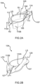
Figs.2A and 2B respectively provide views of an upper surface and a lower surface of a tray according to an example of the invention, and -
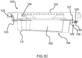
Figs.3A to 3E provide various views of a tray according to the invention coupled to an ironing board. - The invention relates to an accessory for a garment steamer head, which garment steamer head includes a soleplate. The accessory comprises a tray that has an upper surface on which the soleplate is dockable when a descaling operation is to be performed. The tray has a lower surface adapted to cooperate with an external horizontal supporting surface, such as the garment-facing surface of a horizontally orientated ironing board. Attaching means arranged at a front end of the tray enables attachment of a tip of the steamer head to the tray. The tray also has a plurality of supporting ribs comprising lower portions for contacting the external horizontal supporting surface. The supporting ribs are arranged to backwardly protrude beyond a rear end of the soleplate when docked on the tray. Further provided is a garment steamer comprising the accessory and the steamer head.
-
Fig.1 depicts asteamer head 100 of a garment steamer according to an example. Thesteamer head 100 comprises asoleplate 102. - Steam generated by a steam generator (not visible) included in the garment steamer is releasable to a garment via at least one steam vent (not visible) delimited by the
soleplate 102. - The
soleplate 102 comprises a metal alloy or a metal, e.g. aluminium. Such ametallic soleplate 102 is preferably coated, for instance with a material adapted to facilitate gliding of thesoleplate 102 over a fabric. - In at least some embodiments, the
steamer head 100 comprises a casing 101 to which thesoleplate 102 is coupled. Such a casing 101 can be made of any suitable material, such as a plastic material, e.g. an engineering thermoplastic. - Preferably, the
steamer head 100 includes ahandle 103 that, when grasped by the user, enables thesteamer head 100 to be held by the user and moved over a garment. - In some embodiments, the garment steamer comprises a base unit comprising a water tank, and a hose cord for connecting the
steamer head 100 to the base unit. The water tank stores water used to generate steam. To this end, the water stored in the water tank is supplied to the steam generator. - In some embodiments, the steam generator is included in the base unit, and the steam generated by the steam generator is supplied to the
steamer head 100 via the hose cord. - In such embodiments, the
steamer head 100 preferably includes a steam heater arranged to reheat steam and/or water received from the steam generator, prior to the steam exiting the steamer head via the at least one steam vent. The steam heater may assist to minimise the risk of spitting of water onto the garment being treated. - In alternative embodiments, the
steamer head 100 can comprise a steam chamber arranged to generate steam from water supplied, e.g. pumped, thereto from the water tank included in the base unit. - An accessory comprising a
tray 104 is depicted inFigs.1 ,2A and 2B . Thesoleplate 102 is dockable, in other words mountable, on thetray 104 to enable a descaling operation to be performed. The accessory can, for example, be defined by thetray 104. - The
tray 104 can be made of any suitable mechanically and thermally robust material. In some embodiments, thetray 104 is made of a plastic material. For example, thetray 104 is made of polypropylene, e.g. recycled polypropylene. - The
tray 104 can be manufactured in any suitable manner. In some embodiments, thetray 104 is manufactured by plastic injection moulding, for example by injection moulding using polypropylene. - Vaporizing of water, in particular in the steam heater or steam chamber of the
steamer head 100, can result in a build-up of scale over time. The descaling operation can remove at least some of this scale. - The descaling operation can, for example, be implemented using a user-selectable descaling mode of the garment steamer. For example, the garment steamer includes a user interface configured to enable the user to select the descaling mode of the garment steamer.
- Alternatively or additionally, a descaling solution that is different from the water used in normal operation of the garment steamer can be used, for instance by the descaling solution being introduced into the steam heater or steam chamber of the
steamer head 100, for the descaling operation. - In such embodiments, the descaling solution preferably comprises, e.g. is defined by, aqueous acetic acid. The aqueous acetic acid can be provided in any suitable manner, for instance as a mixture of distilled water and white vinegar.
- More generally, during the descaling operation, scale and/or water is or are flushed out from the
steamer head 100, for example via the steam vent(s) delimited by thesoleplate 102. The scale and/or water flushed out from thesteamer head 100 is or are receivable in thetray 104 during the descaling operation. - When the
soleplate 102 is docked on thetray 104, thesoleplate 102 faces an interior of thetray 104. Thetray 104 preferably comprises arecess 105 for receiving scale and/or water from thesteamer head 100 during the descaling operation. - As shown in
Fig.2A , thetray 104 forms an upper surface US on which thesoleplate 102 is dockable, in other words mountable, to enable the descaling operation to be performed. - The
soleplate 102 is preferably supportable on arim 106 that extends at least partly around therecess 105. In such embodiments, the upper surface US can be regarded as being included in therim 106. - The shape of the upper surface US and/or the
rim 106 preferably follows the profile of thesoleplate 102. This can facilitate docking of thesoleplate 102 on thetray 104 by providing an intuitive visual guide to the user for how to dock thesoleplate 102 on thetray 104. - In some embodiments, the upper surface US is arranged to support the
soleplate 102 at an angle relative to a lower surface LS of thetray 104 that cooperates with, e.g. rests on, an external horizontal supporting surface. In other words, a first plane of the upper surface US is angled with respect to a second plane of the lower surface LS. Preferably, this angle is in the range 0 to 5 degrees, preferably 3 degrees, such that when the lower surface LS is arranged on a horizontal surface, the front part of thetray 104 is lower than its rear part. Atray 104 having the upper surface US at an angle relative to a lower surface LS is illustrated inFig.3C . - Thus, the
tray 104 can support thesteamer head 100 at a desired angle during the descaling process. Such an angle can, for instance, be selected to ensure that the descaling solution is able to contact relevant parts of the interior of thesteamer head 100 during the descaling operation, in particular relevant parts of the steam heater or steam chamber at which scale is liable to build up. - In some embodiments, and as best shown in
Fig.2A , one or more soleplate retention members R1, R2 is or are arranged around the upper surface US and upstand(s) from the upper surface US. - The soleplate retention member(s) R1, R2 can assist to minimize or prevent forwards, backwards and/or sidewards lateral movement of the
soleplate 102 on the upper surface US when thesoleplate 102 is docked on thetray 104. - In some embodiments, such as that shown in
Fig.2A , the one or more soleplate retention members R1, R2 include(s) a front soleplate retention member R1 arranged at or proximal to a front end of thetray 104. The front soleplate retention member R1 can assist to minimize or prevent forwards movement of thesoleplate 102 on the upper surface US when thesoleplate 102 is docked on thetray 104. - The front soleplate retention member R1 preferably extends around the upper surface US from a left side of the
tray 104 to the front end to a right side of thetray 104. Thus, the front soleplate retention member R1 can assist to minimize or prevent (at least) forwards and sidewards lateral movement of thesoleplate 102 on the upper surface US when thesoleplate 102 is docked on thetray 104. - Alternatively or additionally, the one or more soleplate retention members R1, R2 include(s) a rear soleplate retention member R2 arranged at or proximal to a
back end 112 of thetray 104. The rear soleplate retention member R2 can assist to minimize or prevent backwards movement of thesoleplate 102 on the upper surface US when thesoleplate 102 is docked on thetray 104. - In some embodiments, such as shown in
Figs.1 ,2A and 2B , thetray 104 comprises aflange 107 extending at least partly around therecess 105. Such aflange 107 can be regarded as projecting laterally outwards away from therecess 105. - The
flange 107 can assist the user to manipulate thetray 104, for example when moving thetray 104 containing water and/or scale. Theflange 107 can also assist with stowing of thetray 104 after use, for instance by assisting coupling of thetray 104 to anironing board 120, as described in more detail herein below with reference toFigs.3A to 3E . - In some embodiments, the one or more soleplate retention members R1, R2 is or are arranged between the upper surface US and the
flange 107, for example between therim 106 and theflange 107. - Referring to
Figs.1 and2A , thetray 104 comprises attaching means 108 arranged at the front end of thetray 104 to attach atip 109 of thesteamer head 100 to thetray 104. - The attaching means 108 can assist to reduce the risk of the
steamer head 100, and thetip 109 in particular, unintentionally separating from thetray 104 during the descaling operation. Thus, the attaching means 108 can assist to ensure safe implementing of the descaling operation. - As best shown in
Fig.2B , thetray 104 forms a lower surface LS adapted to cooperate with an external horizontal and flat supporting surface. For example, the cooperation of the lower surface LS of thetray 104 with the external horizontal supporting surface means that thetray 104 is supportable on the external horizontal supporting surface by the lower surface LS resting on the external horizontal supporting surface. - In this way, the external horizontal supporting surface can support the
tray 104 with thesoleplate 102 of thesteamer head 100 docked thereon when the lower surface LS is cooperating with, for example resting on, the external horizontal supporting surface. - The external horizontal supporting surface can, for example, be provided by a garment-facing
side 122 of theironing board 120, provided that a horizontal orientation is being adopted by theironing board 120. - The lower surface LS can be adapted to cooperate with the external horizontal support surface in any suitable manner. In some embodiments, such as shown in
Fig.2B , the lower surface LS is included in a support foot of thetray 104. For example, the lower surface LS is included in a support foot that extends around at least part of a periphery of an underside of thetray 104. - As shown in
Figs. 1 ,2A and 2B , a plurality of supportingribs rear end 111 of thesoleplate 102 when thesteamer head 100 is docked on thetray 104. - The supporting
ribs tray 104. For example, each of the supportingribs 110, 110B comprises a lower portion LP1, LP2 flush with the lower surface LS of thetray 104. - The lower portions LP1, LP2 being flush with the lower surface LS means that the lower portions LP1, LP2 also cooperate with, for example rest on, the external horizontal supporting surface.
- By the lower portions LP1, LP2 backwardly protruding beyond the
rear end 111 of thesoleplate 102 when thesteamer head 100 is docked on thetray 104, the risk of backwards tipping of thetray 104, with thesoleplate 102 of thesteamer head 100 docked thereon, can be minimized. - It is also noted that the
steamer head 100 can be supported on thetray 104, with thetray 104 sitting stably on the external horizontal supporting surface, without the user being required to hold thesteamer head 100. - By the
tray 104 comprising both the attaching means 108 and the supportingribs tip 109 of thesteamer head 100 separating from thetray 104 and the latter reducing the risk of backwards tipping of thetray 104 together with thesteamer head 100, thesteamer head 100 can be stably supported by thetray 104 during the descaling operation. User convenience can thus be enhanced due to the user not being required to hold thesteamer head 100, and/or user safety can be improved. - In some embodiments, the hose cord connects to the
handle 103 of thesteamer head 100. In such embodiments, the hose cord can connect to, and backwardly extend away from, thehandle 103. In alternative embodiments, the hose cord can connect to, and backwardly extend away from, a rear portion of the casing 101 other than thehandle 103. - More generally, the hose cord preferably backwardly extends away from a rear of the
steamer head 100. This can assist to minimize the risk of the hose cord impeding movement of thesteamer head 100, in particular when thesteamer head 100 is being moved over a garment. - Whilst the hose cord backwardly extending away from the rear of the
steamer head 100 can increase the risk of tilting of thesteamer head 100 during the descaling operation, this risk can be alleviated by the attachingmeans 108. The lower portions LP1, LP2 of the supportingribs tray 104 together with thesteamer head 100. - In some embodiments, such as shown in
Fig.1 , thehandle 103 of thesteamer head 100 backwardly extends beyond a rearmost portion of the casing 101. - This extension of the
handle 103 can assist with maneuverability of thesteamer head 100. Whilst thehandle 103 backwardly extending beyond the rearmost portion of the casing 101 can increase the risk of tilting of thesteamer head 100 during the descaling operation, this risk can be alleviated by the attaching means 108 and the supportingribs - In some embodiments, such as those shown in
Figs.1 ,2A and 2B , the plurality of supportingribs ribs back end 112 of thetray 104. The pair ofribs tray 104 on the external horizontal supporting surface. - In some embodiments, the plurality of supporting
ribs ribs back end 112 of thetray 104. In particular, the optional central rib can assist to reinforce the stabilization provided by the pair ofribs - In such embodiments, the central rib preferably backwardly protrudes by a shorter length than each of the pair of
ribs - The
tip 109 of thesteamer head 100 that is attachable to thetray 104 via the attaching means 108 preferably comprises a tip of the casing 101. - Attaching the
steamer head 100 to thetray 104 via its casing 101 may provide a relatively robust and long-lasting solution, particularly in comparison to, for example, attaching thesteamer head 100 to thetray 104 via a tip of the steamer head's 100soleplate 102 due to the relatively high temperatures to which thesoleplate 102 is heated. - In some embodiments, and as best shown in
Fig.2A , the attaching means 108 comprises acavity 113 for receiving thetip 109 of thesteamer head 100, e.g. thetip 109 comprising the tip of the casing 101. This may provide a relatively straightforwardly manufacturable way of implementing the attachingmeans 108. - In such embodiments, the
cavity 113 is preferably partly defined by anupper wall portion 114, with theupper wall portion 114 being arranged to contact an upper surface of thetip 109 of thesteamer head 100 when thesoleplate 102 is docked on thetray 104. By contacting the upper surface of thetip 109 of thesoleplate 102, theupper wall portion 114 can assist to minimize the risk of tilting of the steamer head 100 (in particular a tilting where the rear extremity of thehandle 103 would tend to get closer to the tray 104). - In some embodiments, such as shown in
Fig. 1 , theupper wall portion 114 is arranged to contact an upwardly facing surface of the tip of the steamer head's 100 casing 101 when thesoleplate 102 is docked on thetray 104. - In some embodiments, such as shown in
Figs.3A to 3E , the garment steamer comprises anironing board 120. A garment is supportable by theironing board 120 during steaming and/or ironing of the garment using thesteamer head 100. - The garment-facing
side 122 of theironing board 120 is the side against which a garment is supportable. Theironing board 120 also has anunderside 124, with the garment-facingside 122 and theunderside 124 facing in opposite directions. In other words, the garment-facingside 122 faces in a first direction and theunderside 124 faces in a second direction that is opposite to the first direction. - In some embodiments, the garment steamer includes a pole assembly (not visible) for supporting the
ironing board 120. In such embodiments, the garment steamer can be regarded as a stand steamer. - The pole assembly is preferably a telescopic pole assembly. In such embodiments, height adjustment of the
ironing board 120 can be implemented by extending and collapsing the telescopic pole assembly. - Alternatively or additionally, the
ironing board 120 is preferably tiltable between a vertical orientation and a horizontal orientation. The vertical orientation can be used for steaming hanging garments, and the horizontal orientation can be used for ironing. In some embodiments, the horizontal orientation is also used for the descaling operation, when theironing board 120 is used to provide the external horizontal supporting surface. - In some embodiments, the garment steamer includes a support base arranged to support the base unit and/or the pole assembly.
- More generally, the garment steamer preferably comprises coupling means to detachably couple the
tray 104 to theironing board 120 when thesoleplate 102 is not being docked on thetray 104. - The coupling means can assist the user to easily retrieve the
tray 104 when the descaling operation is due to be performed, noting that the descaling operation tends to take place, depending on factors such as water hardness and frequency of use of the garment steamer, every few weeks. - The capability to couple the
tray 104 to theironing board 120 of the garment steamer can assist to minimize the risk of thetray 104 being misplaced (in other words located somewhere different from the rest of the garment steamer), and thus assists to ensure compliance with descaling recommendations for the garment steamer. - By reducing the risk of the
tray 104 being misplaced, the user may be more likely to implement the descaling operation when recommended to do so. Alternatively or additionally, the user may be more likely to use thetray 104 for the descaling operation rather than some other receptacle, such as a sink, that is not specifically designed for this purpose. Hence the coupling means can assist to ensure that the descaling operation is performed properly, effectively and safely. It is noted that performing of the descaling operation properly and effectively can assist with ensuring that the garment steamer functions reliably over its operating lifetime. - In some embodiments, such as shown in
Figs.3A to 3E , the coupling means is arranged to detachably couple thetray 104 to theunderside 124 of theironing board 120. By thetray 104 being couplable to theunderside 124 of theironing board 120, thetray 104 can be positioned in a way that minimizes the risk of thetray 104 hampering ironing or steaming of a garment supported by the garment-facingside 122. Moreover, thetray 104 can be conveniently hidden from view when coupled to theironing board 120. - In some embodiments, such as shown in
Figs.3A to 3E , the coupling means comprises at least oneresilient fastener 126 adapted to releasablysecure part 127 of thetray 104 to theironing board 120. - Any suitable type of
resilient fastener 126 can be employed for this purpose. In some embodiments, the at least oneresilient fastener 126 comprises aresilient member 128 and a securingmember 129, with theresilient member 128 being arranged to bias the securingmember 129 into engagement with thepart 127 of thetray 104. - In some embodiments, such as shown in
Figs.3A to 3E , theresilient member 128 comprises, e.g. is defined by, a spring. Any suitable type of spring can be contemplated for inclusion in theresilient member 128, such as a helical spring, as shown inFigs.3C and3D , a leaf spring, etc. - In some embodiments, and with continued reference to
Figs.3C and3D , the at least oneresilient fastener 126 comprises atactile portion 130 contactable and moveable by a user, for instance by a user's finger, to cause movement of the securingmember 129 against the bias provided by theresilient member 128, e.g. spring. - During coupling of the
tray 104 to theironing board 120, the user may move thetactile portion 130 so that the securingmember 129 is positioned to enable thepart 127 of thetray 104 to be moved beyond the securingmember 129 towards the ironingboard 120. Following release of thetactile portion 130 while thepart 127 of thetray 104 remains in position beyond the securingmember 129, the securingmember 129 can engage a bottom surface of thepart 127 in order to secure thepart 127 to theironing board 120. - During release of the
tray 104 from theironing board 120, the user may move thetactile portion 130 so that the securingmember 129 is positioned to enable thepart 127 of thetray 104 to be moved beyond the securingmember 129 away from theironing board 120. It is noted that the movement of thetray 104 towards and away from theironing board 120 is denoted inFig.3A by the double-headed arrow. - The
tactile portion 130 can have any suitable design. In some embodiments, and as best shown inFig.3D , thetactile portion 130 comprises one ormore protrusions tactile portion 130 when moving thetactile portion 130. - In some embodiments, and as best shown in
Figs.3C and3E , the coupling means comprises asupport member 123 against which aportion 125 of thetray 104 is restable while the at least oneresilient fastener 126 secures thepart 127 of thetray 104, with thesupport member 123 and theresilient fastener 126 being thereby arranged to hold thetray 104 to theironing board 120. - In such embodiments, the
portion 125 is preferably at or proximal to a first end of thetray 104, with thepart 127 being at or proximal to a second end of thetray 104 that is opposite the first end. This may provide a relatively straightforwardly manufacturable, secure and easy-to-use coupling component of thetray 104. - For example, the
portion 125 and/or thepart 127 of thetray 104 is or are included in theflange 107 that extends at least partly around therecess 105. - In some embodiments, the at least one resilient fastener comprises a snap-fit fastener. Such a snap-fit fastener may make coupling of the
tray 104 to and detachment of thetray 104 from theironing board 120 relatively staightforward to implement. - The snap-fit fastener can have any suitable design. In some embodiments, the snap-fit fastener comprises, e.g. is, a cantilever snap-fit fastener.
- It is noted that the coupling means can generally be regarded as comprising mounting feature(s) provided on the
ironing board 120, for example on theunderside 124 of theironing board 120. - The coupling means/mounting feature(s) can be made of any suitable material. In some embodiments, the coupling means/mounting features comprise(s) a plastic material, for example polypropylene, e.g. recycled polypropylene.
- The above embodiments as described are only illustrative, and not intended to limit the technique approaches of the present invention. Although the present invention is described in details referring to the preferable embodiments, those skilled in the art will understand that the technique approaches of the present invention can be modified or equally displaced without departing from the protective scope of the claims of the present invention. In the claims, the word "comprising" does not exclude other elements or steps, and the indefinite article "a" or "an" does not exclude a plurality. Any reference signs in the claims should not be construed as limiting the scope.
Claims (15)
- An accessory for a garment steamer head (100) comprising a soleplate (102), the accessory comprising a tray (104),- the tray forming an upper surface (US) on which the soleplate is dockable to enable a descaling operation of the steamer head,- the tray forming a lower surface (LS) adapted to cooperate with an external horizontal supporting surface,- attaching means (108) arranged at a front end of the tray to attach a tip (109) of the steamer head to the tray, and- a plurality of supporting ribs (110A, 110B) comprising lower portions (LP1, LP2) being flush with said lower surface, the supporting ribs being arranged to backwardly protrude beyond a rear end (111) of the soleplate when docked on the tray.
- The accessory according to claim 1, wherein the plurality of supporting ribs (110A, 110B) comprises a pair of ribs (110A, 110B) that are spaced apart from each other across a back end (112) of the tray (104).
- The accessory according to claim 2, wherein the plurality of supporting ribs (110A, 110B) further comprises a central rib arranged between the pair of ribs (110A, 110B).
- The accessory according to claim 3, wherein the central rib backwardly protrudes by a shorter length than each of the pair of ribs (110A, 110B).
- The accessory according to any one of claims 1 to 4, wherein the attaching means (108) comprises a cavity (113) for receiving the tip (109) of the steamer head (100).
- The accessory according to claim 5, wherein the cavity (113) is partly defined by an upper wall portion (114), the upper wall portion being arranged to contact an upper surface of the tip (109) of the steamer head (100).
- The accessory according to any one of claims 1 to 6, wherein the upper surface (US) is arranged to support the soleplate (102) at an angle relative to the lower surface (LS).
- The accessory according to any one of claims 1 to 7, wherein:- the tray (104) comprises a recess (105) for receiving scale and/or water from the steamer head (100) during the descaling operation, and- the upper surface (US) is included in a rim (106) extending at least partly around the recess, the soleplate (102) of the steamer head being supportable on the rim.
- The accessory according to claim 8, wherein the tray (104) further comprises a flange (107) extending at least partly around the recess (105).
- A garment steamer comprising:- a steamer head (100) having a soleplate (102), and- the accessory according to any one of claims 1 to 9.
- The garment steamer according to claim 10, comprising a hose cord arranged to backwardly extend away from a rear of the steamer head (100).
- The garment steamer according to claim 10 or claim 11, comprising:- an ironing board (120), and- coupling means adapted to detachably couple the tray (104) to the ironing board when the soleplate (102) is not being docked on the tray.
- The garment steamer according to claim 12, wherein the ironing board (120) has a garment-facing side (122) against which a garment is supportable, and an underside (124), the garment-facing side and the underside facing in opposite directions, the coupling means being arranged to couple the tray (104) to the underside.
- The garment steamer according to claim 12 or claim 13, wherein the coupling means comprises at least one resilient fastener (126) adapted to releasably secure part (127) of the tray (104) to the ironing board (120).
- The garment steamer according to claim 14, wherein the at least one resilient fastener (126) comprises a resilient member (128) and a securing member (129), the resilient member being arranged to bias the securing member into engagement with the part (127) of the tray (104).
Priority Applications (5)
| Application Number | Priority Date | Filing Date | Title |
|---|---|---|---|
| EP23159198.3A EP4424901A1 (en) | 2023-02-28 | 2023-02-28 | Accessory and garment steamer comprising the same |
| CN202480014916.4A CN120769940A (en) | 2023-02-28 | 2024-01-18 | Accessory and clothes steamer including the same |
| EP23821666.7A EP4673599A1 (en) | 2023-02-28 | 2024-01-18 | Accessory and garment steamer comprising the same |
| PCT/EP2023/085401 WO2024179708A1 (en) | 2023-02-28 | 2024-01-18 | Accessory and garment steamer comprising the same |
| KR1020257032217A KR20250155586A (en) | 2023-02-28 | 2024-01-18 | Accessories and garment steamers including the same |
Applications Claiming Priority (1)
| Application Number | Priority Date | Filing Date | Title |
|---|---|---|---|
| EP23159198.3A EP4424901A1 (en) | 2023-02-28 | 2023-02-28 | Accessory and garment steamer comprising the same |
Publications (1)
| Publication Number | Publication Date |
|---|---|
| EP4424901A1 true EP4424901A1 (en) | 2024-09-04 |
Family
ID=85410165
Family Applications (2)
| Application Number | Title | Priority Date | Filing Date |
|---|---|---|---|
| EP23159198.3A Withdrawn EP4424901A1 (en) | 2023-02-28 | 2023-02-28 | Accessory and garment steamer comprising the same |
| EP23821666.7A Pending EP4673599A1 (en) | 2023-02-28 | 2024-01-18 | Accessory and garment steamer comprising the same |
Family Applications After (1)
| Application Number | Title | Priority Date | Filing Date |
|---|---|---|---|
| EP23821666.7A Pending EP4673599A1 (en) | 2023-02-28 | 2024-01-18 | Accessory and garment steamer comprising the same |
Country Status (4)
| Country | Link |
|---|---|
| EP (2) | EP4424901A1 (en) |
| KR (1) | KR20250155586A (en) |
| CN (1) | CN120769940A (en) |
| WO (1) | WO2024179708A1 (en) |
Families Citing this family (2)
| Publication number | Priority date | Publication date | Assignee | Title |
|---|---|---|---|---|
| USD1096023S1 (en) * | 2025-01-09 | 2025-09-30 | Dongguan Super Electric Technology Co., Ltd | Garment steamer |
| USD1104382S1 (en) * | 2025-03-03 | 2025-12-02 | Junlin HUANG | Handheld garment steamer |
Citations (6)
| Publication number | Priority date | Publication date | Assignee | Title |
|---|---|---|---|---|
| KR870012364U (en) * | 1986-01-24 | 1987-08-04 | 이기문 | Iron stand and protective cover |
| WO2000073171A1 (en) * | 1999-05-27 | 2000-12-07 | Pagter & Partners International B.V. | Packaging for long-stemmed flowers |
| US20180064037A1 (en) * | 2016-09-08 | 2018-03-08 | Fork Farms LLC | Modular plant growth apparatus |
| WO2020053909A1 (en) * | 2018-09-14 | 2020-03-19 | De' Longhi Appliances S.R.L. Con Unico Socio | Support base for an iron |
| WO2021009786A1 (en) * | 2019-07-18 | 2021-01-21 | De' Longhi Appliances S.R.L. Con Unico Socio | Container to collect the washing water of an iron |
| EP3536849B1 (en) * | 2018-03-05 | 2021-02-17 | Tsann Kuen (Zhangzhou) Enterprise Co., Ltd. | Locking mechanism and an ironing device having the same |
-
2023
- 2023-02-28 EP EP23159198.3A patent/EP4424901A1/en not_active Withdrawn
-
2024
- 2024-01-18 WO PCT/EP2023/085401 patent/WO2024179708A1/en not_active Ceased
- 2024-01-18 CN CN202480014916.4A patent/CN120769940A/en active Pending
- 2024-01-18 EP EP23821666.7A patent/EP4673599A1/en active Pending
- 2024-01-18 KR KR1020257032217A patent/KR20250155586A/en active Pending
Patent Citations (6)
| Publication number | Priority date | Publication date | Assignee | Title |
|---|---|---|---|---|
| KR870012364U (en) * | 1986-01-24 | 1987-08-04 | 이기문 | Iron stand and protective cover |
| WO2000073171A1 (en) * | 1999-05-27 | 2000-12-07 | Pagter & Partners International B.V. | Packaging for long-stemmed flowers |
| US20180064037A1 (en) * | 2016-09-08 | 2018-03-08 | Fork Farms LLC | Modular plant growth apparatus |
| EP3536849B1 (en) * | 2018-03-05 | 2021-02-17 | Tsann Kuen (Zhangzhou) Enterprise Co., Ltd. | Locking mechanism and an ironing device having the same |
| WO2020053909A1 (en) * | 2018-09-14 | 2020-03-19 | De' Longhi Appliances S.R.L. Con Unico Socio | Support base for an iron |
| WO2021009786A1 (en) * | 2019-07-18 | 2021-01-21 | De' Longhi Appliances S.R.L. Con Unico Socio | Container to collect the washing water of an iron |
Also Published As
| Publication number | Publication date |
|---|---|
| KR20250155586A (en) | 2025-10-30 |
| CN120769940A (en) | 2025-10-10 |
| EP4673599A1 (en) | 2026-01-07 |
| WO2024179708A1 (en) | 2024-09-06 |
Similar Documents
| Publication | Publication Date | Title |
|---|---|---|
| EP4673599A1 (en) | Accessory and garment steamer comprising the same | |
| CN109953685B (en) | Combination of vacuum cleaner and accessory rack and vacuum cleaner and accessory rack | |
| JP2021520966A (en) | Detachable handle for cookware | |
| JP7023117B2 (en) | Ironing appliances including iron with sole and cantilevered handle to sole | |
| WO2020136366A1 (en) | Storage dock for a battery-powered vacuum cleaner | |
| EP4424902A1 (en) | Garment steamer with a descaling tray and an ironing board | |
| CN118765341B (en) | Bracket for docking iron head and steam device including the bracket | |
| EP4609024A1 (en) | Detachable docking unit for a garment steamer | |
| KR101995347B1 (en) | cordless dual spin damp cloth cleaner | |
| JP6815332B2 (en) | Ironing appliances with iron and base including storage for ironing | |
| EP4647545A1 (en) | Stand steamer comprising support base and detachable water tank | |
| CN211872369U (en) | Apparatus for steam treating laundry | |
| KR20250036878A (en) | Garment steamer with detachable docking unit | |
| KR20250038706A (en) | Garment steamer with detachable docking unit | |
| JP2000300897A (en) | Steam iron | |
| KR101997001B1 (en) | cordless dual spin damp cloth cleaner | |
| CN218599803U (en) | Outdoor cooker | |
| EP4649188A1 (en) | Steaming device comprising a pole assembly and a support base | |
| JP6762902B2 (en) | Steamer | |
| WO2026017541A1 (en) | Steaming device with moveable dock for supporting a steamer head | |
| EP4647544A1 (en) | Garment steamer comprising pole(s)-supported ironing board | |
| JPS63194613A (en) | vacuum cleaner | |
| WO2026048089A1 (en) | Cleaning tool set | |
| JP3113166B2 (en) | Separate electric cooker | |
| JP2003265898A (en) | Steam iron |
Legal Events
| Date | Code | Title | Description |
|---|---|---|---|
| PUAI | Public reference made under article 153(3) epc to a published international application that has entered the european phase |
Free format text: ORIGINAL CODE: 0009012 |
|
| STAA | Information on the status of an ep patent application or granted ep patent |
Free format text: STATUS: THE APPLICATION HAS BEEN PUBLISHED |
|
| AK | Designated contracting states |
Kind code of ref document: A1 Designated state(s): AL AT BE BG CH CY CZ DE DK EE ES FI FR GB GR HR HU IE IS IT LI LT LU LV MC ME MK MT NL NO PL PT RO RS SE SI SK SM TR |
|
| STAA | Information on the status of an ep patent application or granted ep patent |
Free format text: STATUS: THE APPLICATION IS DEEMED TO BE WITHDRAWN |
|
| 18D | Application deemed to be withdrawn |
Effective date: 20250305 |