EP4424535A1 - Vehicular back door - Google Patents
Vehicular back door Download PDFInfo
- Publication number
- EP4424535A1 EP4424535A1 EP23831245.8A EP23831245A EP4424535A1 EP 4424535 A1 EP4424535 A1 EP 4424535A1 EP 23831245 A EP23831245 A EP 23831245A EP 4424535 A1 EP4424535 A1 EP 4424535A1
- Authority
- EP
- European Patent Office
- Prior art keywords
- panel
- adhesive
- recess
- back door
- exemplary embodiment
- Prior art date
- Legal status (The legal status is an assumption and is not a legal conclusion. Google has not performed a legal analysis and makes no representation as to the accuracy of the status listed.)
- Pending
Links
Images


Classifications
-
- B—PERFORMING OPERATIONS; TRANSPORTING
- B60—VEHICLES IN GENERAL
- B60J—WINDOWS, WINDSCREENS, NON-FIXED ROOFS, DOORS, OR SIMILAR DEVICES FOR VEHICLES; REMOVABLE EXTERNAL PROTECTIVE COVERINGS SPECIALLY ADAPTED FOR VEHICLES
- B60J5/00—Doors
- B60J5/10—Doors arranged at the vehicle rear
- B60J5/101—Doors arranged at the vehicle rear for non-load transporting vehicles, i.e. family cars including vans
- B60J5/107—Doors arranged at the vehicle rear for non-load transporting vehicles, i.e. family cars including vans constructional details, e.g. about door frame, panels, materials used, reinforcements
-
- B—PERFORMING OPERATIONS; TRANSPORTING
- B60—VEHICLES IN GENERAL
- B60J—WINDOWS, WINDSCREENS, NON-FIXED ROOFS, DOORS, OR SIMILAR DEVICES FOR VEHICLES; REMOVABLE EXTERNAL PROTECTIVE COVERINGS SPECIALLY ADAPTED FOR VEHICLES
- B60J5/00—Doors
- B60J5/10—Doors arranged at the vehicle rear
- B60J5/101—Doors arranged at the vehicle rear for non-load transporting vehicles, i.e. family cars including vans
-
- B—PERFORMING OPERATIONS; TRANSPORTING
- B32—LAYERED PRODUCTS
- B32B—LAYERED PRODUCTS, i.e. PRODUCTS BUILT-UP OF STRATA OF FLAT OR NON-FLAT, e.g. CELLULAR OR HONEYCOMB, FORM
- B32B3/00—Layered products comprising a layer with external or internal discontinuities or unevennesses, or a layer of non-planar shape; Layered products comprising a layer having particular features of form
- B32B3/02—Layered products comprising a layer with external or internal discontinuities or unevennesses, or a layer of non-planar shape; Layered products comprising a layer having particular features of form characterised by features of form at particular places, e.g. in edge regions
- B32B3/08—Layered products comprising a layer with external or internal discontinuities or unevennesses, or a layer of non-planar shape; Layered products comprising a layer having particular features of form characterised by features of form at particular places, e.g. in edge regions characterised by added members at particular parts
-
- B—PERFORMING OPERATIONS; TRANSPORTING
- B32—LAYERED PRODUCTS
- B32B—LAYERED PRODUCTS, i.e. PRODUCTS BUILT-UP OF STRATA OF FLAT OR NON-FLAT, e.g. CELLULAR OR HONEYCOMB, FORM
- B32B3/00—Layered products comprising a layer with external or internal discontinuities or unevennesses, or a layer of non-planar shape; Layered products comprising a layer having particular features of form
- B32B3/26—Layered products comprising a layer with external or internal discontinuities or unevennesses, or a layer of non-planar shape; Layered products comprising a layer having particular features of form characterised by a particular shape of the outline of the cross-section of a continuous layer; characterised by a layer with cavities or internal voids ; characterised by an apertured layer
- B32B3/30—Layered products comprising a layer with external or internal discontinuities or unevennesses, or a layer of non-planar shape; Layered products comprising a layer having particular features of form characterised by a particular shape of the outline of the cross-section of a continuous layer; characterised by a layer with cavities or internal voids ; characterised by an apertured layer characterised by a layer formed with recesses or projections, e.g. hollows, grooves, protuberances, ribs
-
- B—PERFORMING OPERATIONS; TRANSPORTING
- B32—LAYERED PRODUCTS
- B32B—LAYERED PRODUCTS, i.e. PRODUCTS BUILT-UP OF STRATA OF FLAT OR NON-FLAT, e.g. CELLULAR OR HONEYCOMB, FORM
- B32B5/00—Layered products characterised by the non- homogeneity or physical structure, i.e. comprising a fibrous, filamentary, particulate or foam layer; Layered products characterised by having a layer differing constitutionally or physically in different parts
- B32B5/02—Layered products characterised by the non- homogeneity or physical structure, i.e. comprising a fibrous, filamentary, particulate or foam layer; Layered products characterised by having a layer differing constitutionally or physically in different parts characterised by structural features of a fibrous or filamentary layer
-
- B—PERFORMING OPERATIONS; TRANSPORTING
- B32—LAYERED PRODUCTS
- B32B—LAYERED PRODUCTS, i.e. PRODUCTS BUILT-UP OF STRATA OF FLAT OR NON-FLAT, e.g. CELLULAR OR HONEYCOMB, FORM
- B32B5/00—Layered products characterised by the non- homogeneity or physical structure, i.e. comprising a fibrous, filamentary, particulate or foam layer; Layered products characterised by having a layer differing constitutionally or physically in different parts
- B32B5/22—Layered products characterised by the non- homogeneity or physical structure, i.e. comprising a fibrous, filamentary, particulate or foam layer; Layered products characterised by having a layer differing constitutionally or physically in different parts characterised by the presence of two or more layers which are next to each other and are fibrous, filamentary, formed of particles or foamed
- B32B5/24—Layered products characterised by the non- homogeneity or physical structure, i.e. comprising a fibrous, filamentary, particulate or foam layer; Layered products characterised by having a layer differing constitutionally or physically in different parts characterised by the presence of two or more layers which are next to each other and are fibrous, filamentary, formed of particles or foamed one layer being a fibrous or filamentary layer
- B32B5/26—Layered products characterised by the non- homogeneity or physical structure, i.e. comprising a fibrous, filamentary, particulate or foam layer; Layered products characterised by having a layer differing constitutionally or physically in different parts characterised by the presence of two or more layers which are next to each other and are fibrous, filamentary, formed of particles or foamed one layer being a fibrous or filamentary layer another layer next to it also being fibrous or filamentary
-
- B—PERFORMING OPERATIONS; TRANSPORTING
- B32—LAYERED PRODUCTS
- B32B—LAYERED PRODUCTS, i.e. PRODUCTS BUILT-UP OF STRATA OF FLAT OR NON-FLAT, e.g. CELLULAR OR HONEYCOMB, FORM
- B32B2260/00—Layered product comprising an impregnated, embedded, or bonded layer wherein the layer comprises an impregnation, embedding, or binder material
- B32B2260/02—Composition of the impregnated, bonded or embedded layer
- B32B2260/021—Fibrous or filamentary layer
- B32B2260/023—Two or more layers
-
- B—PERFORMING OPERATIONS; TRANSPORTING
- B32—LAYERED PRODUCTS
- B32B—LAYERED PRODUCTS, i.e. PRODUCTS BUILT-UP OF STRATA OF FLAT OR NON-FLAT, e.g. CELLULAR OR HONEYCOMB, FORM
- B32B2260/00—Layered product comprising an impregnated, embedded, or bonded layer wherein the layer comprises an impregnation, embedding, or binder material
- B32B2260/04—Impregnation, embedding, or binder material
- B32B2260/046—Synthetic resin
-
- B—PERFORMING OPERATIONS; TRANSPORTING
- B32—LAYERED PRODUCTS
- B32B—LAYERED PRODUCTS, i.e. PRODUCTS BUILT-UP OF STRATA OF FLAT OR NON-FLAT, e.g. CELLULAR OR HONEYCOMB, FORM
- B32B2262/00—Composition or structural features of fibres which form a fibrous or filamentary layer or are present as additives
- B32B2262/10—Inorganic fibres
- B32B2262/101—Glass fibres
-
- B—PERFORMING OPERATIONS; TRANSPORTING
- B32—LAYERED PRODUCTS
- B32B—LAYERED PRODUCTS, i.e. PRODUCTS BUILT-UP OF STRATA OF FLAT OR NON-FLAT, e.g. CELLULAR OR HONEYCOMB, FORM
- B32B2605/00—Vehicles
-
- B—PERFORMING OPERATIONS; TRANSPORTING
- B60—VEHICLES IN GENERAL
- B60J—WINDOWS, WINDSCREENS, NON-FIXED ROOFS, DOORS, OR SIMILAR DEVICES FOR VEHICLES; REMOVABLE EXTERNAL PROTECTIVE COVERINGS SPECIALLY ADAPTED FOR VEHICLES
- B60J5/00—Doors
- B60J5/04—Doors arranged at the vehicle sides
- B60J5/048—Doors arranged at the vehicle sides characterised by the material
- B60J5/0481—Doors arranged at the vehicle sides characterised by the material plastic
Definitions
- the present disclosure relates to a vehicular back door.
- a resin-made back door for closing off an openable/closeable back door opening formed in a rear wall of a vehicle body of a vehicle is known, such as described in Japanese Patent No. 6884466 .
- the body of the back door may be configured by joining together a resin-made inner panel and a resin-made outer panel using an adhesive.
- an inner panel and an outer panel will sometimes be collectively referred to simply by "panel members”.
- an adhesive is disposed on a planned adhesion region pre-set on a join face of one of the panel members. Then a join face of the other panel member is caused to approach the planned adhesion region on the surface of the one panel member by movement along a pre-set approach direction.
- Japanese Patent No. 6884466 A technology related to joining using adhesive is disclosed in Japanese Patent No. 6884466 .
- a recess on an outer panel that is open toward an inner panel, and a protruding portion on the inner panel that corresponds to the recess of the outer panel, are joined together a position of an eave part on a rear spoiler section of a back door outer panel.
- the protruding portion of the inner panel includes an inclined surface inclined with respect to a horizontal direction along the approach direction of the two panel members.
- the inclined surface includes a horizontal component along the approach direction, and a perpendicular component that intersects perpendicularly with the horizontal direction.
- Japanese Patent No. 6884466 describes the adhesive strength between the inner panel and the outer panel being raised by the inclined surface including the perpendicular component being included in an adhesion region of the join section.
- Patent Document 1 Japanese Patent No. 6884466
- two panel members rub against each other includes both a state in which the join faces of the respective panel members move relative to each other without adhesive interposed between the two panel members, and a state in which the join faces of the two panel members move relative to each other with adhesive interposed between the two panel members.
- the present disclosure has focused on the above issues, and provides a vehicular back door capable of improving the waterproofness of an adhesion region in a join section of a back door.
- the present disclosure enables provision of a vehicular back door capable of improving the waterproofness of an adhesion region of a join section of a back door.
- Fig. 1 is a cross-section taken along line 1-1 of Fig. 4 .
- the vehicular back door 10 according to the present exemplary embodiment includes a first panel 12, a second panel 14, a first adhesive 18A, a second adhesive 18B, a third adhesive 18C, and brackets 26.
- back door is sometimes simply referred to as "back door”.
- the back door 10 is provided so as to be capable of opening and closing an opening in a rear section of a vehicle body of a vehicle.
- a front-rear direction X and an up-down direction Z of the vehicle body are each indicated by two directional arrows in Fig. 1 .
- a vehicle body width direction Y intersects perpendicularly with both the front-rear direction X and the up-down direction Z.
- the first panel 12 and the second panel 14 are both members that configure the back door 10.
- Both the first panel 12 and the second panel 14 are made from resin and, for example, may be molded using an injection molding machine.
- a glass fiber composite polypropylene material containing glass fiber at a specific content by weight % may, for example, be employed in the first panel 12.
- a polypropylene material compounded with talc or rubber may, for example, be employed in the second panel 14.
- the resin material employed to mold the panel members is not particularly limited.
- the resin employed as the resin material is, for example, preferably at least one resin selected from the group consisting of a polypropylene (PP) resin, a polypropylene composite (PPC) resin, and an Acrylonitrile-Butadiene-Styrene copolymer (ABS) co-polymer resin.
- PP polypropylene
- PPC polypropylene composite
- ABS Acrylonitrile-Butadiene-Styrene copolymer
- the first panel 12 is an inner panel
- the second panel 14 is an outer panel
- the first panel may be an outer panel
- the second panel may be an inner panel
- a shape and plate thickness of the first panel 12 can be freely set according to the desired design.
- the shape and plate thickness of the second panel 14 can be freely set according to the desired design.
- the second panel 14 includes two recesses that open toward the first panel 12. Specifically, in the present exemplary embodiment the second panel 14 includes a first recess 14A positioned at a lower side in Fig. 1 , and a second recess 14B positioned at an upper side in Fig. 1 . In other words, there are two protruding portions that protrude toward a right side of the front-rear direction X in Fig. 1 , namely toward a rear side of the vehicle, disposed in a row along the up-down direction Z on the outer panel of the second panel 14 of the present exemplary embodiment. Note that in the present disclosure the number of individual recesses formed to the panel member can be set freely to any number of one or greater.
- the second recess 14B of the present exemplary embodiment includes a first side wall 14B1, a second side wall 14B2, and a bottom 14B3.
- the first side wall 14B1 is inclined downward from the horizontal direction on progression toward the right side of the front-rear direction X in Fig. 1 .
- first side wall 14B1 and the second side wall 14B2 in the second recess 14B approach each other on progression toward the bottom 14B3.
- shape of the recess can be freely set in the present disclosure.
- a pair of side walls may separate from each other on progression toward the bottom.
- a portion of the first panel 12 facing toward the second recess 14B of the second panel 14 is flat. Namely, the first panel 12 does not follow the shape of the second recess 14B of the second panel 14.
- Fig. 1 illustrates an example in which the first recess 14A of the second panel 14 is bent at an angle of substantially 90°, and a first protruding portion 12A of the first panel 12 follows the first recess 14A.
- the bend angle of the panel member can be freely set and is not limited to 90°.
- the first adhesive 18A joins together the first panel 12 and the second panel 14.
- another member may be disposed between the two panel members.
- the back door may be configured by indirect joining.
- the second adhesive 18B joins together the brackets 26 and the first panel 12.
- the brackets 26 and the first panel 12 may be joined together by, instead of using the second adhesive 18B, being joined together with welding by thermal welding or ultrasonic welding, for example.
- the third adhesive 18C joins together the brackets 26 and the second panel 14.
- the brackets 26 and the second panel 14 may be joined together by, instead of using the third adhesive 18C, being joined together with welding by thermal welding or ultrasonic welding, for example.
- the second adhesive 18B and the third adhesive 18C are linked to the first adhesive 18A.
- the second adhesive 18B and the third adhesive 18C may be separated from the first adhesive 18A.
- the present disclosure encompasses indirect joining that is a state in which another member is disposed between the panel members and the brackets.
- the brackets 26 are made from resin, and may also be molded using an injection molding machine, for example.
- an Acrylate Styrene Acrylonitrile (ASA) resin may, for example, be employed in the brackets 26 of the present exemplary embodiment.
- ASA Acrylate Styrene Acrylonitrile
- the resin material employed to mold the bracket is not particularly limited.
- the brackets 26 are separate members from each of the first panel 12 and the second panel 14.
- the brackets 26 are interposed between the first panel 12 and the second panel 14. Namely, the brackets 26 couple together the first panel 12 and the second panel 14.
- Each of the brackets 26 includes a base 26A and a protrusion 26B.
- the base 26A is a plate shaped member made from resin.
- the base 26A includes a first base portion 26A1 to be positioned on the inside of the second recess 14B, and a second base portion 26A2 that is contiguous to the first base portion 26A1 and bends around at a left end of the first base portion 26A1 and extends downward as illustrated in Fig. 1 .
- the first base portion 26A1 extends along a side wall of the second recess 14B of the second panel 14 in Fig. 1 .
- the second base portion 26A2 extends along the first panel 12 and the second panel 14 at a lower side of the second recess 14B in Fig. 1 .
- the protrusion 26B is a plate shaped member made from resin.
- the material of the protrusion 26B may be any material capable of being joined to the panel members, and may be a metal, for example.
- the protrusion 26B is contiguous to the base 26A, and in a joined state of the bracket 26 and the second panel 14 projects further outside than the j oined member.
- the protrusion 26B includes a first wall 26B1, a second wall 26B2, and a lid portion 26B3, as illustrated in Fig. 1 .
- the first wall 26B1 extends upward in Fig. 1 from a position in the vicinity of a boundary between the first base portion 26A1 and the second base portion 26A2 of the base 26A.
- the second wall 26B2 extends upward from a right end of the first base portion 26A1 of the base 26A in Fig. 1 .
- the lid portion 26B3 links together the first wall 26B1 and the second wall 26B2 at a position on the upper side of and inside the second recess 14B.
- the first wall 26B1 is joined to the first panel 12.
- the second wall 26B2 is joined to the second panel 14.
- the lid portion 26B3 may be omitted.
- the first base portion 26A1 of the base 26A and the protrusion 26B of the bracket 26 are disposed inside the second recess 14B of the second panel 14.
- the third adhesive 18C is disposed on the join face of the second panel 14 in a planned adhesion region pre-set for joining to the bracket 26.
- the adhesive may, for example, be disposed in a string shape on the planned adhesion region by being externally extruded continuously from inside a nozzle at a leading end of a dedicated tube or hose.
- the join face of the bracket 26 is caused to approach the planned adhesion region for the bracket 26 on the second panel 14 along the pre-set approach direction.
- the first base portion 26A1 of the base 26A and the protrusion 26B of the bracket 26 are inserted into the second recess 14B of the second panel 14.
- the join face of the base 26A of the bracket 26, and the join face of the second wall 26B2 of the protrusion 26B are then superimposed on the join face of the second panel 14.
- the second adhesive 18B is disposed on a planned adhesion region pre-set for joining to the first panel 12 on the join face of the bracket 26.
- the first adhesive 18A is disposed on a planned adhesion region pre-set for joining to the first panel 12 on the join face of the second panel 14.
- the first adhesive 18A and the second adhesive 18B are standardized with a single adhesive. Namely, disposing the second adhesive 18B on the planned adhesion region and disposing the first adhesive 18A on the planned adhesion region may be performed continuously. Note that in the present disclosure the first adhesive and the second adhesive may differ from each other.
- the join face of the first panel 12 is caused to approach the planned adhesion region for the first panel 12 on the brackets 26 along the pre-set approach direction.
- the approach direction of the first panel 12 is a horizontal direction along the front-rear direction X in Fig. 1 .
- the approach direction may be freely set.
- the join face of the first panel 12 is caused to approach the planned adhesion region for the first panel 12 on the second panel 14 along an approach direction that is a horizontal direction.
- the first protruding portion 12A of the first panel 12 is inserted into the first recess 14A of the second panel 14.
- join face of the second base portion 26A2 of the base 26A of the bracket 26 and the join face of the first panel 12 are then superimposed on each other.
- join face of the first wall 26B1 of the protrusion 26B and the join face of the first panel 12 are superimposed on each other.
- join face at the position of the first recess 14A of the second panel 14 and the join face at the first protruding portion 12A of the first panel 12 are superimposed on each other.
- the two panel members that have their join faces superimposed on each other are joined together by the adhesive curing. In the present exemplary embodiment, no rubbing together arises between the first panel 12 and the second panel 14 when the first panel 12 is caused to approach the second panel 14 along the horizontal direction, even though each of the brackets 26 is being inserted into the second recess 14B.
- a vehicular back door 10Z according to a comparative example with reference to Fig. 5 to Fig. 6 .
- Points of difference in the vehicular back door 10Z according to the comparative example compared to the present exemplary embodiment are that the brackets 26 are not provided and that a second protruding portion 12B is provided to the first panel 12.
- the second protruding portion 12B is inserted into the second recess 14B when the first panel 12 is caused to approach the second panel 14 along a horizontal direction.
- FIG. 5 an approach direction of the two panel members along the front-rear direction X is indicated by the rightward facing hollow arrow.
- a first side wall 14B1 at a lower side of the second recess 14B is inclined downward on progression in the front-rear direction X from the left side toward the right side in Fig. 5 .
- a portion below a lower edge of an opening of the second recess 14B in Fig. 5 is contained in the region B.
- a groove acting as a pathway for water may be formed over the entire join face at the region B in the join section. Namely, in cross-section, suppose imaginary lines are set extending along the approach direction from edges of the opening of the recess, then when superimposing the two panel members deformation is liable to occur at the adhesive on the side wall of the recess and at the adhesive on the bottom side of the recess at portions positioned outside the recess from the imaginary lines.
- the first protruding portion 12A of the first panel 12 needs to be inserted into the first recess 14A at a lower side of the second recess 14B of the second panel 14 in Fig. 5 .
- a pathway for water formed in the adhesion region is expressed as being a groove in the present exemplary embodiment, in the present disclosure an expression other than groove may be employed for the pathway for water, such as an intermittent gap for example. Namely, the expression for a pathway for water is not dependent on how it looks in plan view, or how it looks in cross-section.
- Fig. 5 an example is illustrated in Fig. 5 of a state in which a leading end of the protruding portion of the first panel 12 is inclined downward from the horizontal direction, namely, a state in which the leading end of the protruding portion is inclined in a direction intersecting with the approach direction of the two panel members.
- the first adhesive 18A may be pulled toward the inside of the recess of the second panel 14 at a position of the opening in the recess even in a state in which the leading end of the protruding portion of the first panel 12 has a form along the approach direction of the two panel members.
- Fig. 6A illustrates an example in which the approach direction of the two panel members is indicated by a rightward facing hollow arrow.
- an upstand angle ⁇ from an opening edge of a side wall at a position of the opening of the recess is substantially 90°.
- the second panel 14 includes the second recess 14B opening toward the first panel 12, and also the bracket 26 is disposed inside the second recess 14B.
- the waterproofness of the adhesion region in the join section of the back door 10 is accordingly improved.
- bracket 26 is a separate member to both the first panel 12 and the second panel 14. This increases the degrees of freedom for design of the panel members during design of the panel member by an amount commensurate with not needing a protruding portion.
- the joining between the bracket 26 and the first panel 12 is performed using the second adhesive 18B
- the joining between the bracket 26 and the second panel 14 is performed using the third adhesive 18C
- the second adhesive 18B and the third adhesive 18C are linked to the first adhesive 18A. Namely, an operation to join together the three members of the first panel 12, the second panel 14, and the bracket 26 is standardized in the point that adhesive is employed therefor. This thereby enables the overall operational efficiency to be improved in the joining operation.
- the present disclosure is not limited to a back door of a vehicle and is, for example, applicable to adhesion regions of panel portions made from resin in various vehicle components such as a bumper, a side mudguard, a fender, a back door garnish, a spoiler, and a radiator.
- vehicle components such as a bumper, a side mudguard, a fender, a back door garnish, a spoiler, and a radiator.
- the present disclosure is not limited to vehicle components and is, for example, applicable to adhesion regions of panel portions made from resin configuring various structural bodies other than a vehicle, such as railway equipment or a building.
- the present disclosure includes various exemplary embodiments not described above, and the technical scope of the present disclosure is determined from the above description by the invention determining matter in the scope of the appropriate patent claims.
Landscapes
- Engineering & Computer Science (AREA)
- Mechanical Engineering (AREA)
- Standing Axle, Rod, Or Tube Structures Coupled By Welding, Adhesion, Or Deposition (AREA)
Abstract
Description
- The present disclosure relates to a vehicular back door.
- Hitherto, a resin-made back door for closing off an openable/closeable back door opening formed in a rear wall of a vehicle body of a vehicle is known, such as described in
Japanese Patent No. 6884466 - In an operation to join two panel members together, for example, first an adhesive is disposed on a planned adhesion region pre-set on a join face of one of the panel members. Then a join face of the other panel member is caused to approach the planned adhesion region on the surface of the one panel member by movement along a pre-set approach direction.
- As a result of this approach, the join face of the other panel member contacts peaks in the adhesive, and the join faces of the two panel members are superimposed on each other. After the join faces have been superimposed the two panel members are joined together by the adhesive curing.
- A technology related to joining using adhesive is disclosed in
Japanese Patent No. 6884466 Japanese Patent No. 6884466 - Patent Document 1:
Japanese Patent No. 6884466 - When the two panel members approach each other in the joining operation, a state might arise in which the two panel members rub against each other while a surface of the other panel member has contacted the adhesive on the surface of the one panel member. Note that in the present specification "two panel members rub against each other" includes both a state in which the join faces of the respective panel members move relative to each other without adhesive interposed between the two panel members, and a state in which the join faces of the two panel members move relative to each other with adhesive interposed between the two panel members.
- Due to the two panel members rubbing against each other, a state might arise in which the adhesive on the surface of the panel member is pulled, or a state might arise in which adhesive taken off from the adhesive region. The adhesive would accordingly be locally deformed, with this possibly resulting in a groove being formed between the surface of the adhesive at the deformed position and the join face of the panel member after the adhesive has cured. Such a formed groove forms a pathway for water such as rain to pass through, with a concern that this might lead to a drop in waterproofness in the adhesion region of the back door.
- With regard to this point, even when the protruding portion of the inner panel has an inclined surface including a perpendicular component such as described in
Japanese Patent No. 6884466 Japanese Patent No. 6884466 - The present disclosure has focused on the above issues, and provides a vehicular back door capable of improving the waterproofness of an adhesion region in a join section of a back door.
- Specific means to achieve the above objectives are set out below.
- <1> A vehicular back door including:
- a first panel that is made from resin;
- a second panel that is made from resin and that includes a recess that is open toward the first panel;
- a first adhesive that joins together the first panel and the second panel; and
- a bracket that is a separate member from each of the first panel and the second panel, and that is disposed inside the recess.
- <2> The vehicular back door according to <1>, wherein:
- the bracket is sandwiched between the first panel and the second panel;
- the vehicular back door further includes
- a second adhesive that joins together the bracket and the first panel, and
- a third adhesive that joins together the bracket and the second panel; and
the second adhesive and the third adhesive are linked to the first adhesive.
- The present disclosure enables provision of a vehicular back door capable of improving the waterproofness of an adhesion region of a join section of a back door.
-
-
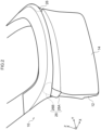
Fig. 1 is a cross-section to explain a vehicular back door according to an exemplary embodiment of the present disclosure. -
Fig. 2 is a perspective view to explain a vehicular back door according to the present exemplary embodiment. -
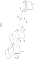
Fig. 3 is an exploded assembly diagram to explain a vehicular back door according to the present exemplary embodiment. -
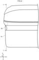
Fig. 4 is a front view to explain a vehicular back door according to the present exemplary embodiment. -
Fig. 5 is a cross-section to explain a vehicular back door according to a comparative example. -
Fig. 6A is a cross-section to explain a state of adhesive deformation when a protruding portion of a first panel is inserted into a recess of a second panel in a vehicular back door according to a comparative example. -
Fig. 6B is a cross-section to explain a state in which a groove has been formed at a portion where adhesive has deformed in a vehicular back door according to a comparative example. - Description follows regarding an exemplary embodiment of the present disclosure. Similar reference numerals are appended to similar portions in the following description of the drawings. However, the drawings are merely schematic, and relations between thickness and plane dimensions, and ratios of thicknesses in each device and each member, differ from actual ratios. This means that the specific thicknesses and dimensions should be determined while referring to the following description. Moreover, there are also portions where the relationship of dimensions and ratios differ from each other between the respective drawings. Moreover, unless explicitly stated otherwise in the present specification, there is no limitation to there being one item of each configuration element in the present disclosure, and there may be plural present thereof.
- Description follows regarding a
vehicular back door 10 according to the present exemplary embodiment, with reference toFig. 1 to Fig. 4 .Fig. 1 is a cross-section taken along line 1-1 ofFig. 4 . As illustrated inFig. 1 , thevehicular back door 10 according to the present exemplary embodiment includes afirst panel 12, asecond panel 14, a first adhesive 18A, a second adhesive 18B, a third adhesive 18C, andbrackets 26. Note that for ease of explanation, hereafter vehicular back door is sometimes simply referred to as "back door". - The
back door 10 is provided so as to be capable of opening and closing an opening in a rear section of a vehicle body of a vehicle. A front-rear direction X and an up-down direction Z of the vehicle body are each indicated by two directional arrows inFig. 1 . A vehicle body width direction Y intersects perpendicularly with both the front-rear direction X and the up-down direction Z. - As illustrated in
Fig. 2 , thefirst panel 12 and thesecond panel 14 are both members that configure theback door 10. Both thefirst panel 12 and thesecond panel 14 are made from resin and, for example, may be molded using an injection molding machine. Specifically, a glass fiber composite polypropylene material containing glass fiber at a specific content by weight % may, for example, be employed in thefirst panel 12. A polypropylene material compounded with talc or rubber may, for example, be employed in thesecond panel 14. - Note that in the present disclosure the resin material employed to mold the panel members is not particularly limited. The resin employed as the resin material is, for example, preferably at least one resin selected from the group consisting of a polypropylene (PP) resin, a polypropylene composite (PPC) resin, and an Acrylonitrile-Butadiene-Styrene copolymer (ABS) co-polymer resin.
- In the present exemplary embodiment the
first panel 12 is an inner panel, and thesecond panel 14 is an outer panel. However, in the present disclosure the first panel may be an outer panel, and the second panel may be an inner panel. Moreover, a shape and plate thickness of thefirst panel 12 can be freely set according to the desired design. Similarly, the shape and plate thickness of thesecond panel 14 can be freely set according to the desired design. - The
second panel 14 includes two recesses that open toward thefirst panel 12. Specifically, in the present exemplary embodiment thesecond panel 14 includes afirst recess 14A positioned at a lower side inFig. 1 , and asecond recess 14B positioned at an upper side inFig. 1 . In other words, there are two protruding portions that protrude toward a right side of the front-rear direction X inFig. 1 , namely toward a rear side of the vehicle, disposed in a row along the up-down direction Z on the outer panel of thesecond panel 14 of the present exemplary embodiment. Note that in the present disclosure the number of individual recesses formed to the panel member can be set freely to any number of one or greater. - The
second recess 14B of the present exemplary embodiment includes a first side wall 14B1, a second side wall 14B2, and a bottom 14B3. The first side wall 14B1 is inclined downward from the horizontal direction on progression toward the right side of the front-rear direction X inFig. 1 . - In the present exemplary embodiment, the first side wall 14B1 and the second side wall 14B2 in the
second recess 14B approach each other on progression toward the bottom 14B3. Note that the shape of the recess can be freely set in the present disclosure. For example, a pair of side walls may separate from each other on progression toward the bottom. - As illustrated in
Fig. 1 , a portion of thefirst panel 12 facing toward thesecond recess 14B of thesecond panel 14 is flat. Namely, thefirst panel 12 does not follow the shape of thesecond recess 14B of thesecond panel 14. - However, a portion of the
first panel 12 facing toward thefirst recess 14A of thesecond panel 14 follows the shape of thefirst recess 14A.Fig. 1 illustrates an example in which thefirst recess 14A of thesecond panel 14 is bent at an angle of substantially 90°, and a first protrudingportion 12A of thefirst panel 12 follows thefirst recess 14A. Note that in the present disclosure the bend angle of the panel member can be freely set and is not limited to 90°. - As illustrated in
Fig. 3 to Fig. 4 , thefirst adhesive 18A joins together thefirst panel 12 and thesecond panel 14. Moreover, although in the present exemplary embodiment an example is illustrated of a state in which two panel members are joined together, in the present disclosure another member may be disposed between the two panel members. Namely, the back door may be configured by indirect joining. - Moreover, in the present exemplary embodiment the
second adhesive 18B joins together thebrackets 26 and thefirst panel 12. In the present disclosure, thebrackets 26 and thefirst panel 12 may be joined together by, instead of using thesecond adhesive 18B, being joined together with welding by thermal welding or ultrasonic welding, for example. - Moreover, in the present exemplary embodiment the
third adhesive 18C joins together thebrackets 26 and thesecond panel 14. In the present disclosure, thebrackets 26 and thesecond panel 14 may be joined together by, instead of using thethird adhesive 18C, being joined together with welding by thermal welding or ultrasonic welding, for example. - Moreover, in the present exemplary embodiment, the second adhesive 18B and the third adhesive 18C are linked to the
first adhesive 18A. In the present disclosure the second adhesive 18B and the third adhesive 18C may be separated from thefirst adhesive 18A. - Moreover, although in the present exemplary embodiment an example is illustrated of a state in which the panel members and the
brackets 26 are joined together, the present disclosure encompasses indirect joining that is a state in which another member is disposed between the panel members and the brackets. - The
brackets 26 are made from resin, and may also be molded using an injection molding machine, for example. Specifically, an Acrylate Styrene Acrylonitrile (ASA) resin may, for example, be employed in thebrackets 26 of the present exemplary embodiment. Note that in the present disclosure the resin material employed to mold the bracket is not particularly limited. - The
brackets 26 are separate members from each of thefirst panel 12 and thesecond panel 14. Thebrackets 26 are interposed between thefirst panel 12 and thesecond panel 14. Namely, thebrackets 26 couple together thefirst panel 12 and thesecond panel 14. Each of thebrackets 26 includes abase 26A and aprotrusion 26B. - The
base 26A is a plate shaped member made from resin. Thebase 26A includes a first base portion 26A1 to be positioned on the inside of thesecond recess 14B, and a second base portion 26A2 that is contiguous to the first base portion 26A1 and bends around at a left end of the first base portion 26A1 and extends downward as illustrated inFig. 1 . The first base portion 26A1 extends along a side wall of thesecond recess 14B of thesecond panel 14 inFig. 1 . The second base portion 26A2 extends along thefirst panel 12 and thesecond panel 14 at a lower side of thesecond recess 14B inFig. 1 . - In the present exemplary embodiment the
protrusion 26B is a plate shaped member made from resin. In the present disclosure the material of theprotrusion 26B may be any material capable of being joined to the panel members, and may be a metal, for example. Theprotrusion 26B is contiguous to thebase 26A, and in a joined state of thebracket 26 and thesecond panel 14 projects further outside than the j oined member. - The
protrusion 26B includes a first wall 26B1, a second wall 26B2, and a lid portion 26B3, as illustrated inFig. 1 . The first wall 26B1 extends upward inFig. 1 from a position in the vicinity of a boundary between the first base portion 26A1 and the second base portion 26A2 of thebase 26A. The second wall 26B2 extends upward from a right end of the first base portion 26A1 of thebase 26A inFig. 1 . The lid portion 26B3 links together the first wall 26B1 and the second wall 26B2 at a position on the upper side of and inside thesecond recess 14B. - The first wall 26B1 is joined to the
first panel 12. The second wall 26B2 is joined to thesecond panel 14. In the present disclosure the lid portion 26B3 may be omitted. The first base portion 26A1 of thebase 26A and theprotrusion 26B of thebracket 26 are disposed inside thesecond recess 14B of thesecond panel 14. - Next, description follows regarding a joining operation according to the present exemplary embodiment. In an operation to join the two panel members together, first the
third adhesive 18C is disposed on the join face of thesecond panel 14 in a planned adhesion region pre-set for joining to thebracket 26. The adhesive may, for example, be disposed in a string shape on the planned adhesion region by being externally extruded continuously from inside a nozzle at a leading end of a dedicated tube or hose. - Then the join face of the
bracket 26 is caused to approach the planned adhesion region for thebracket 26 on thesecond panel 14 along the pre-set approach direction. As a result of this approach, the first base portion 26A1 of thebase 26A and theprotrusion 26B of thebracket 26 are inserted into thesecond recess 14B of thesecond panel 14. The join face of thebase 26A of thebracket 26, and the join face of the second wall 26B2 of theprotrusion 26B are then superimposed on the join face of thesecond panel 14. - Next, the
second adhesive 18B is disposed on a planned adhesion region pre-set for joining to thefirst panel 12 on the join face of thebracket 26. Moreover, thefirst adhesive 18A is disposed on a planned adhesion region pre-set for joining to thefirst panel 12 on the join face of thesecond panel 14. In the present exemplary embodiment, thefirst adhesive 18A and the second adhesive 18B are standardized with a single adhesive. Namely, disposing the second adhesive 18B on the planned adhesion region and disposing the first adhesive 18A on the planned adhesion region may be performed continuously. Note that in the present disclosure the first adhesive and the second adhesive may differ from each other. - Next, the join face of the
first panel 12 is caused to approach the planned adhesion region for thefirst panel 12 on thebrackets 26 along the pre-set approach direction. In the present exemplary embodiment the approach direction of thefirst panel 12 is a horizontal direction along the front-rear direction X inFig. 1 . Note that in the present disclosure the approach direction may be freely set. Moreover, the join face of thefirst panel 12 is caused to approach the planned adhesion region for thefirst panel 12 on thesecond panel 14 along an approach direction that is a horizontal direction. As a result of this approach, the first protrudingportion 12A of thefirst panel 12 is inserted into thefirst recess 14A of thesecond panel 14. - The join face of the second base portion 26A2 of the
base 26A of thebracket 26 and the join face of thefirst panel 12 are then superimposed on each other. Moreover, the join face of the first wall 26B1 of theprotrusion 26B and the join face of thefirst panel 12 are superimposed on each other. Moreover, the join face at the position of thefirst recess 14A of thesecond panel 14 and the join face at the first protrudingportion 12A of thefirst panel 12 are superimposed on each other. The two panel members that have their join faces superimposed on each other are joined together by the adhesive curing. In the present exemplary embodiment, no rubbing together arises between thefirst panel 12 and thesecond panel 14 when thefirst panel 12 is caused to approach thesecond panel 14 along the horizontal direction, even though each of thebrackets 26 is being inserted into thesecond recess 14B. - Next, description follows regarding a
vehicular back door 10Z according to a comparative example, with reference toFig. 5 to Fig. 6 . Points of difference in thevehicular back door 10Z according to the comparative example compared to the present exemplary embodiment are that thebrackets 26 are not provided and that a second protrudingportion 12B is provided to thefirst panel 12. As illustrated inFig. 5 , in the comparative example the second protrudingportion 12B is inserted into thesecond recess 14B when thefirst panel 12 is caused to approach thesecond panel 14 along a horizontal direction. - In
Fig. 5 , an approach direction of the two panel members along the front-rear direction X is indicated by the rightward facing hollow arrow. A first side wall 14B1 at a lower side of thesecond recess 14B is inclined downward on progression in the front-rear direction X from the left side toward the right side inFig. 5 . This means that when the second protrudingportion 12B is being inserted into asecond recess 14B, rubbing arises between thefirst panel 12 and thesecond panel 14 as in a region B indicated by diagonal shading inside thefirst adhesive 18A inFig. 5 , and as a result thefirst adhesive 18A is readily deformed by this rubbing together. - A portion below a lower edge of an opening of the
second recess 14B inFig. 5 is contained in the region B. Invehicular back door 10Z according to the comparative example, a groove acting as a pathway for water may be formed over the entire join face at the region B in the join section. Namely, in cross-section, suppose imaginary lines are set extending along the approach direction from edges of the opening of the recess, then when superimposing the two panel members deformation is liable to occur at the adhesive on the side wall of the recess and at the adhesive on the bottom side of the recess at portions positioned outside the recess from the imaginary lines. - Moreover, in the comparative example, the first protruding
portion 12A of thefirst panel 12 needs to be inserted into thefirst recess 14A at a lower side of thesecond recess 14B of thesecond panel 14 inFig. 5 . This means that it is difficult to avoid rubbing together of the two panel members due to causing the second protrudingportion 12B of thefirst panel 12 to approach thefirst side wall 14B 1 of thesecond panel 14 in a head-on direction, namely from an upper side toward the lower side inFig. 5 . - Note that although a pathway for water formed in the adhesion region is expressed as being a groove in the present exemplary embodiment, in the present disclosure an expression other than groove may be employed for the pathway for water, such as an intermittent gap for example. Namely, the expression for a pathway for water is not dependent on how it looks in plan view, or how it looks in cross-section.
- Moreover, an example is illustrated in
Fig. 5 of a state in which a leading end of the protruding portion of thefirst panel 12 is inclined downward from the horizontal direction, namely, a state in which the leading end of the protruding portion is inclined in a direction intersecting with the approach direction of the two panel members. However, as illustrated inFig. 6A , thefirst adhesive 18A may be pulled toward the inside of the recess of thesecond panel 14 at a position of the opening in the recess even in a state in which the leading end of the protruding portion of thefirst panel 12 has a form along the approach direction of the two panel members. -
Fig. 6A illustrates an example in which the approach direction of the two panel members is indicated by a rightward facing hollow arrow. In the recess of thesecond panel 14 inFig. 6A , an upstand angle θ from an opening edge of a side wall at a position of the opening of the recess is substantially 90°. Due to thefirst adhesive 18A being pulled toward the inside of the recess of thesecond panel 14, a groove G is formed in an adhesion region between the two panel members at a position of the opening of the recess as illustrated inFig. 6B . Note that the groove G is even more liable to be formed when the upstand angle θ is less than 90°. - In the
back door 10 according to the present exemplary embodiment, thesecond panel 14 includes thesecond recess 14B opening toward thefirst panel 12, and also thebracket 26 is disposed inside thesecond recess 14B. In the present exemplary embodiment, there is no protruding portion formed to thefirst panel 12 for fitting into thesecond recess 14B, with this meaning that deformation at the surface of the adhesive due to rubbing together of the two panel members is not liable to arise in a superposition operation. The waterproofness of the adhesion region in the join section of theback door 10 is accordingly improved. - Moreover, in the present exemplary embodiment the
bracket 26 is a separate member to both thefirst panel 12 and thesecond panel 14. This increases the degrees of freedom for design of the panel members during design of the panel member by an amount commensurate with not needing a protruding portion. - Moreover, in the present exemplary embodiment the joining between the
bracket 26 and thefirst panel 12 is performed using thesecond adhesive 18B, and the joining between thebracket 26 and thesecond panel 14 is performed using thethird adhesive 18C. The second adhesive 18B and the third adhesive 18C are linked to thefirst adhesive 18A. Namely, an operation to join together the three members of thefirst panel 12, thesecond panel 14, and thebracket 26 is standardized in the point that adhesive is employed therefor. This thereby enables the overall operational efficiency to be improved in the joining operation. - Although the present disclosure has been described using the exemplary embodiments disclosed above, the statements and drawings that make up part of this disclosure should not be understood as being limitations to the present disclosure.
- For example, the present disclosure is not limited to a back door of a vehicle and is, for example, applicable to adhesion regions of panel portions made from resin in various vehicle components such as a bumper, a side mudguard, a fender, a back door garnish, a spoiler, and a radiator. Moreover, the present disclosure is not limited to vehicle components and is, for example, applicable to adhesion regions of panel portions made from resin configuring various structural bodies other than a vehicle, such as railway equipment or a building. The present disclosure includes various exemplary embodiments not described above, and the technical scope of the present disclosure is determined from the above description by the invention determining matter in the scope of the appropriate patent claims.
- The entire content of the disclosure of
Japanese Patent Application No. 2022-103844 - Moreover, all publications, patent applications and technical standards mentioned in the present specification are incorporated by reference in the present specification to the same extent as if each individual publication, patent application, or technical standard was specifically and individually indicated to be incorporated by reference.
-
- 10
- vehicular back door
- 10Z
- vehicular back door
- 12
- first panel
- 12A
- first protruding portion
- 12B
- second protruding portion
- 14
- second panel
- 14A
- first recess
- 14B
- second recess
- 14B1
- first side wall
- 14B2
- second side wall
- 14B3
- bottom
- 18A
- first adhesive
- 18B
- second adhesive
- 18C
- third adhesive
- 26
- bracket
- 26A
- base
- 26A1
- first base portion
- 26A2
- second base portion
- 26B
- protrusion
- 26B1
- first wall
- 26B2
- second wall
- 26B3
- lid portion
- B
- region
- G
- groove
- X
- front-rear direction
- Y
- width direction
- Z
- up-down direction
- θ
- upstand angle
Claims (2)
- A vehicular back door, comprising:a first panel that is made from resin;a second panel that is made from resin and that includes a recess that is open toward the first panel;a first adhesive that joins together the first panel and the second panel; anda bracket that is a separate member from each of the first panel and the second panel, and that is disposed inside the recess.
- The vehicular back door according to claim 1, wherein:the bracket is sandwiched between the first panel and the second panel;the vehicular back door further comprises:a second adhesive that joins together the bracket and the first panel, anda third adhesive that joins together the bracket and the second panel; and the second adhesive and the third adhesive are linked to the first adhesive.
Applications Claiming Priority (2)
| Application Number | Priority Date | Filing Date | Title |
|---|---|---|---|
| JP2022103844 | 2022-06-28 | ||
| PCT/JP2023/023025 WO2024004799A1 (en) | 2022-06-28 | 2023-06-21 | Vehicular back door |
Publications (2)
| Publication Number | Publication Date |
|---|---|
| EP4424535A1 true EP4424535A1 (en) | 2024-09-04 |
| EP4424535A4 EP4424535A4 (en) | 2025-03-05 |
Family
ID=89382888
Family Applications (1)
| Application Number | Title | Priority Date | Filing Date |
|---|---|---|---|
| EP23831245.8A Pending EP4424535A4 (en) | 2022-06-28 | 2023-06-21 | VEHICLE REAR DOOR |
Country Status (5)
| Country | Link |
|---|---|
| US (1) | US20240391306A1 (en) |
| EP (1) | EP4424535A4 (en) |
| JP (1) | JPWO2024004799A1 (en) |
| CN (1) | CN118159436A (en) |
| WO (1) | WO2024004799A1 (en) |
Family Cites Families (8)
| Publication number | Priority date | Publication date | Assignee | Title |
|---|---|---|---|---|
| JPH0537689Y2 (en) * | 1987-05-13 | 1993-09-24 | ||
| WO2010067405A1 (en) * | 2008-12-12 | 2010-06-17 | ダイキョーニシカワ株式会社 | Vehicle window panel |
| JP2011057188A (en) * | 2009-09-14 | 2011-03-24 | Kanto Auto Works Ltd | Arrangement structure of resin door |
| JP6243250B2 (en) * | 2014-02-19 | 2017-12-06 | ダイハツ工業株式会社 | Vehicle door |
| JP2016030586A (en) * | 2014-07-30 | 2016-03-07 | トヨタ自動車株式会社 | Resin back door structure for vehicles |
| JP6156354B2 (en) * | 2014-12-24 | 2017-07-05 | トヨタ自動車株式会社 | Resin back door for vehicles |
| JP6884466B2 (en) | 2017-03-30 | 2021-06-09 | ダイハツ工業株式会社 | Adhesive surface structure of back door inner panel and back door outer panel |
| JP2022103844A (en) | 2020-12-28 | 2022-07-08 | 株式会社グッドケア | Body temperature measuring apparatus |
-
2023
- 2023-06-21 WO PCT/JP2023/023025 patent/WO2024004799A1/en not_active Ceased
- 2023-06-21 JP JP2024530742A patent/JPWO2024004799A1/ja active Pending
- 2023-06-21 US US18/695,982 patent/US20240391306A1/en active Pending
- 2023-06-21 EP EP23831245.8A patent/EP4424535A4/en active Pending
- 2023-06-21 CN CN202380014183.XA patent/CN118159436A/en active Pending
Also Published As
| Publication number | Publication date |
|---|---|
| JPWO2024004799A1 (en) | 2024-01-04 |
| CN118159436A (en) | 2024-06-07 |
| US20240391306A1 (en) | 2024-11-28 |
| EP4424535A4 (en) | 2025-03-05 |
| WO2024004799A1 (en) | 2024-01-04 |
Similar Documents
| Publication | Publication Date | Title |
|---|---|---|
| US6729424B2 (en) | Radiator core support structure of motor vehicle | |
| US7316448B2 (en) | Cowl top cover | |
| CN105691168A (en) | vehicle back door assembling method and vehicle back door | |
| JP2015067015A (en) | Cowl top cover | |
| CN108688731A (en) | Vehicle front body structure | |
| US10167021B2 (en) | Vehicular resin panel structure and luggage door | |
| JP5502016B2 (en) | Vehicle door | |
| CN105246741B (en) | Mounting structure for vehicular resin component | |
| JP2015217926A (en) | Cowl cover device | |
| EP4424535A1 (en) | Vehicular back door | |
| US9272604B2 (en) | Molding for vehicle and attachment structure of molding in vehicle | |
| US20240424875A1 (en) | Joint structure and vehicular back door | |
| JP5422594B2 (en) | Exterior members for vehicles | |
| US20080138586A1 (en) | Hybrid structure and method | |
| KR102586929B1 (en) | Tail gate panel aseembly improving stiffness | |
| JP6185775B2 (en) | Cowl top cover | |
| JP5895889B2 (en) | Back door structure and manufacturing method thereof | |
| CN208698902U (en) | A kind of automobile middle sliding door threshold mounting structure | |
| JP2025043068A (en) | Vehicle Structure | |
| JP2009262714A (en) | Mounting structure of air dam skirt for vehicle | |
| JP2009023536A (en) | Joining structure of kicking plate | |
| CN214112477U (en) | Front bumper assembly and vehicle | |
| CN223803647U (en) | Roof crossbeam assembly and vehicle | |
| JP7822264B2 (en) | Vehicle rear structure | |
| CN213861801U (en) | Glass run channel |
Legal Events
| Date | Code | Title | Description |
|---|---|---|---|
| STAA | Information on the status of an ep patent application or granted ep patent |
Free format text: STATUS: THE INTERNATIONAL PUBLICATION HAS BEEN MADE |
|
| PUAI | Public reference made under article 153(3) epc to a published international application that has entered the european phase |
Free format text: ORIGINAL CODE: 0009012 |
|
| STAA | Information on the status of an ep patent application or granted ep patent |
Free format text: STATUS: REQUEST FOR EXAMINATION WAS MADE |
|
| 17P | Request for examination filed |
Effective date: 20240528 |
|
| AK | Designated contracting states |
Kind code of ref document: A1 Designated state(s): AL AT BE BG CH CY CZ DE DK EE ES FI FR GB GR HR HU IE IS IT LI LT LU LV MC ME MK MT NL NO PL PT RO RS SE SI SK SM TR |
|
| STAA | Information on the status of an ep patent application or granted ep patent |
Free format text: STATUS: EXAMINATION IS IN PROGRESS |
|
| A4 | Supplementary search report drawn up and despatched |
Effective date: 20250203 |
|
| RIC1 | Information provided on ipc code assigned before grant |
Ipc: B60J 5/04 20060101ALN20250128BHEP Ipc: B60J 5/10 20060101AFI20250128BHEP |
|
| 17Q | First examination report despatched |
Effective date: 20250217 |
|
| DAV | Request for validation of the european patent (deleted) | ||
| DAX | Request for extension of the european patent (deleted) |