EP4424491A1 - Kneading extruder, control method therefor, and production method for resin compound - Google Patents
Kneading extruder, control method therefor, and production method for resin compound Download PDFInfo
- Publication number
- EP4424491A1 EP4424491A1 EP22886361.9A EP22886361A EP4424491A1 EP 4424491 A1 EP4424491 A1 EP 4424491A1 EP 22886361 A EP22886361 A EP 22886361A EP 4424491 A1 EP4424491 A1 EP 4424491A1
- Authority
- EP
- European Patent Office
- Prior art keywords
- raw material
- resin raw
- filler
- supply
- extruder
- Prior art date
- Legal status (The legal status is an assumption and is not a legal conclusion. Google has not performed a legal analysis and makes no representation as to the accuracy of the status listed.)
- Pending
Links
Images






Classifications
-
- B—PERFORMING OPERATIONS; TRANSPORTING
- B29—WORKING OF PLASTICS; WORKING OF SUBSTANCES IN A PLASTIC STATE IN GENERAL
- B29C—SHAPING OR JOINING OF PLASTICS; SHAPING OF MATERIAL IN A PLASTIC STATE, NOT OTHERWISE PROVIDED FOR; AFTER-TREATMENT OF THE SHAPED PRODUCTS, e.g. REPAIRING
- B29C48/00—Extrusion moulding, i.e. expressing the moulding material through a die or nozzle which imparts the desired form; Apparatus therefor
- B29C48/25—Component parts, details or accessories; Auxiliary operations
- B29C48/36—Means for plasticising or homogenising the moulding material or forcing it through the nozzle or die
- B29C48/395—Means for plasticising or homogenising the moulding material or forcing it through the nozzle or die using screws surrounded by a cooperating barrel, e.g. single screw extruders
-
- B—PERFORMING OPERATIONS; TRANSPORTING
- B29—WORKING OF PLASTICS; WORKING OF SUBSTANCES IN A PLASTIC STATE IN GENERAL
- B29B—PREPARATION OR PRETREATMENT OF THE MATERIAL TO BE SHAPED; MAKING GRANULES OR PREFORMS; RECOVERY OF PLASTICS OR OTHER CONSTITUENTS OF WASTE MATERIAL CONTAINING PLASTICS
- B29B7/00—Mixing; Kneading
- B29B7/30—Mixing; Kneading continuous, with mechanical mixing or kneading devices
- B29B7/58—Component parts, details or accessories; Auxiliary operations
- B29B7/72—Measuring, controlling or regulating
-
- B—PERFORMING OPERATIONS; TRANSPORTING
- B29—WORKING OF PLASTICS; WORKING OF SUBSTANCES IN A PLASTIC STATE IN GENERAL
- B29B—PREPARATION OR PRETREATMENT OF THE MATERIAL TO BE SHAPED; MAKING GRANULES OR PREFORMS; RECOVERY OF PLASTICS OR OTHER CONSTITUENTS OF WASTE MATERIAL CONTAINING PLASTICS
- B29B7/00—Mixing; Kneading
- B29B7/30—Mixing; Kneading continuous, with mechanical mixing or kneading devices
- B29B7/34—Mixing; Kneading continuous, with mechanical mixing or kneading devices with movable mixing or kneading devices
- B29B7/38—Mixing; Kneading continuous, with mechanical mixing or kneading devices with movable mixing or kneading devices rotary
-
- B—PERFORMING OPERATIONS; TRANSPORTING
- B29—WORKING OF PLASTICS; WORKING OF SUBSTANCES IN A PLASTIC STATE IN GENERAL
- B29B—PREPARATION OR PRETREATMENT OF THE MATERIAL TO BE SHAPED; MAKING GRANULES OR PREFORMS; RECOVERY OF PLASTICS OR OTHER CONSTITUENTS OF WASTE MATERIAL CONTAINING PLASTICS
- B29B7/00—Mixing; Kneading
- B29B7/30—Mixing; Kneading continuous, with mechanical mixing or kneading devices
- B29B7/34—Mixing; Kneading continuous, with mechanical mixing or kneading devices with movable mixing or kneading devices
- B29B7/38—Mixing; Kneading continuous, with mechanical mixing or kneading devices with movable mixing or kneading devices rotary
- B29B7/40—Mixing; Kneading continuous, with mechanical mixing or kneading devices with movable mixing or kneading devices rotary with single shaft
- B29B7/42—Mixing; Kneading continuous, with mechanical mixing or kneading devices with movable mixing or kneading devices rotary with single shaft with screw or helix
-
- B—PERFORMING OPERATIONS; TRANSPORTING
- B29—WORKING OF PLASTICS; WORKING OF SUBSTANCES IN A PLASTIC STATE IN GENERAL
- B29B—PREPARATION OR PRETREATMENT OF THE MATERIAL TO BE SHAPED; MAKING GRANULES OR PREFORMS; RECOVERY OF PLASTICS OR OTHER CONSTITUENTS OF WASTE MATERIAL CONTAINING PLASTICS
- B29B7/00—Mixing; Kneading
- B29B7/30—Mixing; Kneading continuous, with mechanical mixing or kneading devices
- B29B7/34—Mixing; Kneading continuous, with mechanical mixing or kneading devices with movable mixing or kneading devices
- B29B7/38—Mixing; Kneading continuous, with mechanical mixing or kneading devices with movable mixing or kneading devices rotary
- B29B7/46—Mixing; Kneading continuous, with mechanical mixing or kneading devices with movable mixing or kneading devices rotary with more than one shaft
- B29B7/48—Mixing; Kneading continuous, with mechanical mixing or kneading devices with movable mixing or kneading devices rotary with more than one shaft with intermeshing devices, e.g. screws
-
- B—PERFORMING OPERATIONS; TRANSPORTING
- B29—WORKING OF PLASTICS; WORKING OF SUBSTANCES IN A PLASTIC STATE IN GENERAL
- B29B—PREPARATION OR PRETREATMENT OF THE MATERIAL TO BE SHAPED; MAKING GRANULES OR PREFORMS; RECOVERY OF PLASTICS OR OTHER CONSTITUENTS OF WASTE MATERIAL CONTAINING PLASTICS
- B29B7/00—Mixing; Kneading
- B29B7/30—Mixing; Kneading continuous, with mechanical mixing or kneading devices
- B29B7/58—Component parts, details or accessories; Auxiliary operations
- B29B7/60—Component parts, details or accessories; Auxiliary operations for feeding, e.g. end guides for the incoming material
- B29B7/603—Component parts, details or accessories; Auxiliary operations for feeding, e.g. end guides for the incoming material in measured doses, e.g. proportioning of several materials
-
- B—PERFORMING OPERATIONS; TRANSPORTING
- B29—WORKING OF PLASTICS; WORKING OF SUBSTANCES IN A PLASTIC STATE IN GENERAL
- B29B—PREPARATION OR PRETREATMENT OF THE MATERIAL TO BE SHAPED; MAKING GRANULES OR PREFORMS; RECOVERY OF PLASTICS OR OTHER CONSTITUENTS OF WASTE MATERIAL CONTAINING PLASTICS
- B29B7/00—Mixing; Kneading
- B29B7/80—Component parts, details or accessories; Auxiliary operations
- B29B7/802—Constructions or methods for cleaning the mixing or kneading device
-
- B—PERFORMING OPERATIONS; TRANSPORTING
- B29—WORKING OF PLASTICS; WORKING OF SUBSTANCES IN A PLASTIC STATE IN GENERAL
- B29B—PREPARATION OR PRETREATMENT OF THE MATERIAL TO BE SHAPED; MAKING GRANULES OR PREFORMS; RECOVERY OF PLASTICS OR OTHER CONSTITUENTS OF WASTE MATERIAL CONTAINING PLASTICS
- B29B7/00—Mixing; Kneading
- B29B7/80—Component parts, details or accessories; Auxiliary operations
- B29B7/88—Adding charges, i.e. additives
- B29B7/90—Fillers or reinforcements, e.g. fibres
-
- B—PERFORMING OPERATIONS; TRANSPORTING
- B29—WORKING OF PLASTICS; WORKING OF SUBSTANCES IN A PLASTIC STATE IN GENERAL
- B29C—SHAPING OR JOINING OF PLASTICS; SHAPING OF MATERIAL IN A PLASTIC STATE, NOT OTHERWISE PROVIDED FOR; AFTER-TREATMENT OF THE SHAPED PRODUCTS, e.g. REPAIRING
- B29C48/00—Extrusion moulding, i.e. expressing the moulding material through a die or nozzle which imparts the desired form; Apparatus therefor
- B29C48/25—Component parts, details or accessories; Auxiliary operations
- B29C48/269—Extrusion in non-steady condition, e.g. start-up or shut-down
-
- B—PERFORMING OPERATIONS; TRANSPORTING
- B29—WORKING OF PLASTICS; WORKING OF SUBSTANCES IN A PLASTIC STATE IN GENERAL
- B29C—SHAPING OR JOINING OF PLASTICS; SHAPING OF MATERIAL IN A PLASTIC STATE, NOT OTHERWISE PROVIDED FOR; AFTER-TREATMENT OF THE SHAPED PRODUCTS, e.g. REPAIRING
- B29C48/00—Extrusion moulding, i.e. expressing the moulding material through a die or nozzle which imparts the desired form; Apparatus therefor
- B29C48/25—Component parts, details or accessories; Auxiliary operations
- B29C48/269—Extrusion in non-steady condition, e.g. start-up or shut-down
- B29C48/2692—Material change
-
- B—PERFORMING OPERATIONS; TRANSPORTING
- B29—WORKING OF PLASTICS; WORKING OF SUBSTANCES IN A PLASTIC STATE IN GENERAL
- B29C—SHAPING OR JOINING OF PLASTICS; SHAPING OF MATERIAL IN A PLASTIC STATE, NOT OTHERWISE PROVIDED FOR; AFTER-TREATMENT OF THE SHAPED PRODUCTS, e.g. REPAIRING
- B29C48/00—Extrusion moulding, i.e. expressing the moulding material through a die or nozzle which imparts the desired form; Apparatus therefor
- B29C48/25—Component parts, details or accessories; Auxiliary operations
- B29C48/285—Feeding the extrusion material to the extruder
- B29C48/286—Raw material dosing
-
- B—PERFORMING OPERATIONS; TRANSPORTING
- B29—WORKING OF PLASTICS; WORKING OF SUBSTANCES IN A PLASTIC STATE IN GENERAL
- B29C—SHAPING OR JOINING OF PLASTICS; SHAPING OF MATERIAL IN A PLASTIC STATE, NOT OTHERWISE PROVIDED FOR; AFTER-TREATMENT OF THE SHAPED PRODUCTS, e.g. REPAIRING
- B29C48/00—Extrusion moulding, i.e. expressing the moulding material through a die or nozzle which imparts the desired form; Apparatus therefor
- B29C48/25—Component parts, details or accessories; Auxiliary operations
- B29C48/285—Feeding the extrusion material to the extruder
- B29C48/288—Feeding the extrusion material to the extruder in solid form, e.g. powder or granules
-
- B—PERFORMING OPERATIONS; TRANSPORTING
- B29—WORKING OF PLASTICS; WORKING OF SUBSTANCES IN A PLASTIC STATE IN GENERAL
- B29C—SHAPING OR JOINING OF PLASTICS; SHAPING OF MATERIAL IN A PLASTIC STATE, NOT OTHERWISE PROVIDED FOR; AFTER-TREATMENT OF THE SHAPED PRODUCTS, e.g. REPAIRING
- B29C48/00—Extrusion moulding, i.e. expressing the moulding material through a die or nozzle which imparts the desired form; Apparatus therefor
- B29C48/25—Component parts, details or accessories; Auxiliary operations
- B29C48/285—Feeding the extrusion material to the extruder
- B29C48/297—Feeding the extrusion material to the extruder at several locations, e.g. using several hoppers or using a separate additive feeding
-
- B—PERFORMING OPERATIONS; TRANSPORTING
- B29—WORKING OF PLASTICS; WORKING OF SUBSTANCES IN A PLASTIC STATE IN GENERAL
- B29C—SHAPING OR JOINING OF PLASTICS; SHAPING OF MATERIAL IN A PLASTIC STATE, NOT OTHERWISE PROVIDED FOR; AFTER-TREATMENT OF THE SHAPED PRODUCTS, e.g. REPAIRING
- B29C48/00—Extrusion moulding, i.e. expressing the moulding material through a die or nozzle which imparts the desired form; Apparatus therefor
- B29C48/25—Component parts, details or accessories; Auxiliary operations
- B29C48/92—Measuring, controlling or regulating
-
- B—PERFORMING OPERATIONS; TRANSPORTING
- B29—WORKING OF PLASTICS; WORKING OF SUBSTANCES IN A PLASTIC STATE IN GENERAL
- B29C—SHAPING OR JOINING OF PLASTICS; SHAPING OF MATERIAL IN A PLASTIC STATE, NOT OTHERWISE PROVIDED FOR; AFTER-TREATMENT OF THE SHAPED PRODUCTS, e.g. REPAIRING
- B29C2948/00—Indexing scheme relating to extrusion moulding
- B29C2948/92—Measuring, controlling or regulating
- B29C2948/92504—Controlled parameter
- B29C2948/9258—Velocity
- B29C2948/9259—Angular velocity
-
- B—PERFORMING OPERATIONS; TRANSPORTING
- B29—WORKING OF PLASTICS; WORKING OF SUBSTANCES IN A PLASTIC STATE IN GENERAL
- B29C—SHAPING OR JOINING OF PLASTICS; SHAPING OF MATERIAL IN A PLASTIC STATE, NOT OTHERWISE PROVIDED FOR; AFTER-TREATMENT OF THE SHAPED PRODUCTS, e.g. REPAIRING
- B29C2948/00—Indexing scheme relating to extrusion moulding
- B29C2948/92—Measuring, controlling or regulating
- B29C2948/92504—Controlled parameter
- B29C2948/9258—Velocity
- B29C2948/926—Flow or feed rate
-
- B—PERFORMING OPERATIONS; TRANSPORTING
- B29—WORKING OF PLASTICS; WORKING OF SUBSTANCES IN A PLASTIC STATE IN GENERAL
- B29C—SHAPING OR JOINING OF PLASTICS; SHAPING OF MATERIAL IN A PLASTIC STATE, NOT OTHERWISE PROVIDED FOR; AFTER-TREATMENT OF THE SHAPED PRODUCTS, e.g. REPAIRING
- B29C2948/00—Indexing scheme relating to extrusion moulding
- B29C2948/92—Measuring, controlling or regulating
- B29C2948/92819—Location or phase of control
- B29C2948/92828—Raw material handling or dosing, e.g. active hopper or feeding device
-
- B—PERFORMING OPERATIONS; TRANSPORTING
- B29—WORKING OF PLASTICS; WORKING OF SUBSTANCES IN A PLASTIC STATE IN GENERAL
- B29C—SHAPING OR JOINING OF PLASTICS; SHAPING OF MATERIAL IN A PLASTIC STATE, NOT OTHERWISE PROVIDED FOR; AFTER-TREATMENT OF THE SHAPED PRODUCTS, e.g. REPAIRING
- B29C2948/00—Indexing scheme relating to extrusion moulding
- B29C2948/92—Measuring, controlling or regulating
- B29C2948/92819—Location or phase of control
- B29C2948/9298—Start-up, shut-down or parameter setting phase; Emergency shut-down; Material change; Test or laboratory equipment or studies
-
- B—PERFORMING OPERATIONS; TRANSPORTING
- B29—WORKING OF PLASTICS; WORKING OF SUBSTANCES IN A PLASTIC STATE IN GENERAL
- B29C—SHAPING OR JOINING OF PLASTICS; SHAPING OF MATERIAL IN A PLASTIC STATE, NOT OTHERWISE PROVIDED FOR; AFTER-TREATMENT OF THE SHAPED PRODUCTS, e.g. REPAIRING
- B29C48/00—Extrusion moulding, i.e. expressing the moulding material through a die or nozzle which imparts the desired form; Apparatus therefor
- B29C48/25—Component parts, details or accessories; Auxiliary operations
- B29C48/285—Feeding the extrusion material to the extruder
- B29C48/288—Feeding the extrusion material to the extruder in solid form, e.g. powder or granules
- B29C48/2886—Feeding the extrusion material to the extruder in solid form, e.g. powder or granules of fillers or of fibrous materials, e.g. short-fibre reinforcements
Definitions
- the present invention relates to a kneading extrusion apparatus, its control method, and a method for manufacturing a resin compound.
- Patent Literature 1 the inventors have previously developed a method for automatically controlling an extruder when the extruder is started in a kneading extrusion apparatus.
- Patent Literature 1 Japanese Unexamined Patent Application Publication No. 2019-69585
- the inventors have examined automatic control for an extruder in a kneading extrusion apparatus that is performed when the extruder is started or stopped.
- the inventors have found that the following problem occurs when a resin compound containing a filler as well as a resin raw material is manufactured by using a kneading extrusion apparatus.
- the filler does not melt inside the extruder, its flowability inside the extruder is low. Therefore, if the filler is supplied to the extruder in a state where there is no resin raw material inside the extruder, there is a risk that the extruder could break down, so it is necessary to be particularly careful in performing the automatic control when the extruder is started or stopped.
- a kneading extrusion apparatus when an extruder is started in order to manufacture a resin compound, an amount of a resin raw material to be supplied is increased with an increase in a rotation speed of a screw of the extruder based on a predetermined starting-time supply pattern for the resin raw material, and based on a predetermined starting-time supply pattern for a filler, a supply of the filler is started after the supplying of the resin raw material is started, and an amount of the filler to be supplied is increased with the increase in the rotation speed of the screw.
- a kneading extrusion apparatus when an extruder is stopped, an amount of a resin raw material to be supplied is reduced with a decrease in a rotation speed of a screw of the extruder based on a predetermined stopping-time supply pattern for the resin raw material, and based on a predetermined stopping-time supply pattern for a filler, an amount of the filler to be supplied is reduced with the increase in the rotation speed of the screw, and the supply of the filler is stopped before the supplying of the resin raw material is stopped.
- Fig. 1 is a schematic cross-sectional diagram showing the overall configuration of the kneading extrusion apparatus according to the first embodiment.
- a resin compound containing a filler dispersed in the resin is extruded and molded by using the kneading extrusion apparatus according to this embodiment.
- the resin compound extruded and molded by the kneading extrusion apparatus according to this embodiment has, for example, a strand-like shape.
- the shape of the extruded and molded resin compound is not limited to any particular shapes, and it may have, for example, a film-like shape.
- the kneading extrusion apparatus includes a resin raw material feeder F1, a filler feeder F2, an extruder 10, and a die 20.
- the resin raw material feeder (first feeder) F1 is a feeder for supplying a resin raw material, which is a main raw material of a resin compound, into the cylinder 11 of the extruder 10.
- the resin raw material feeder F1 shown in Fig. 1 is a screw-type feeder and includes a feeder hopper FH1, a feeder screw FS1, and a feeder motor FM1.
- the resin raw material is not limited to any particular materials, and is, for example, resin pellets or the like made of polypropylene, polyethylene, polyamide, polyethylene terephthalate, or the like.
- the resin raw material is charged into the feeder hopper FH1 and stored therein.
- the feeder screw FS1 is rotationally driven by the feeder motor FM1
- the resin raw material stored in the feeder hopper FH1 is supplied into the cylinder 11 through a hopper 13 of the extruder 10.
- the supply amount of the resin raw material from the resin raw material feeder F1 to the extruder 10 is controlled by a controller CNT shown in Fig. 2 .
- the resin raw material feeder F1 shown in Fig. 1 is a screw-type feeder, a vibration-type feeder or any of other type of feeder may be used as long as the supply amount of the resin raw material can be controlled by the controller CNT, i.e., by a computer.
- the filler feeder (second feeder) F2 is a feeder for supplying a filler, which is one of the components constituting the resin compound, into the cylinder 11 of the extruder 10.
- the filler feeder F2 shown in Fig. 1 is a screw-type feeder and includes a feeder hopper FH2, a feeder screw FS2, and a feeder motor FM2.
- the filler is not limited to any particular fillers, and is, for example, talc, a calcium carbonate powder, glass fibers, a carbon powder, or the like.
- the filler is charged into the feeder hopper FH2 and stored therein.
- the filler stored in the feeder hopper FH2 is supplied into the cylinder 11 through a side supply port 14 of the extruder 10.
- the supply amount of the filler from the filler feeder F2 to the extruder 10 is controlled by the controller CNT shown in Fig. 2 .
- the filler feeder F2 shown in Fig. 1 is a screw-type feeder, a vibration-type feeder or any of other types of feeders may be used as long as the supply amount of the filler can be controlled by the controller CNT, i.e., by a computer.
- a side feeder may be provided between the filler feeder F2 and the side supply port 14, and the filler sent from the filler feeder F2 may be charged into the side supply port 14 through the side feeder.
- the filler may be supplied from the filler feeder F2 into the cylinder 11 through the hopper 13 of the extruder 10 instead of being supplied through the side supply port 14.
- the extruder 10 is a screw extruder.
- a screw 12 extending in the x-axis direction is housed inside the cylinder 11 extending in the x-axis direction.
- the hopper (first supply port) 13 for supplying the resin raw material from the resin raw material feeder F1 into the cylinder 11 is provided above the end part of the cylinder 11 on the upstream side thereof in the extrusion direction (i.e., on the x-axis negative side).
- the side supply port (second supply port) 14 for supplying the filler from the filler feeder F2 is provided on the side surface of the cylinder 11 on the downstream side in the extrusion direction (i.e., on the x-axis positive side), that is, on the die 20 side from the hopper 13.
- the upstream side of the cylinder 11 in the extrusion direction is simply referred to as the "upstream side”
- downstream side thereof in the extrusion direction is simply referred to as the "downstream side”.
- a screw motor SM is connected to the root of the screw 12 with a reduction gear RG interposed therebetween.
- the screw motor SM is a driving source for driving the screw 12. For example, it is possible to control the rotation speed of the screw 12 by controlling the rotation speed of the screw motor SM.
- the screw 12 may be composed of one screw or a plurality of screws.
- an extruder 10 including only one screw 12 is called a single-screw extruder, and an extruder 10 including two screws 12 is called a twin-screw extruder.
- the resin raw material supplied from the hopper 13 is conveyed by the screw motor SM from the root of the rotating screw 12 to the tip thereof, i.e., from the upstream side to the downstream side.
- the resin raw material is heated and sheared by the rotating screw 12 inside the cylinder 11, so that the resin raw material is melted.
- a heater(s) for heating the interior of the cylinder 11 is provided on the outer peripheral surface of the cylinder 11 over substantially the entire area thereof in the longitudinal direction.
- shearing and melting of the resin raw material supplied from the hopper 13 are mainly carried out in a kneading zone KZ1 of the extruder 10 shown in Fig. 1 .
- a vent V1 is provided in the upper surface of the cylinder 11 on the downstream side near the kneading zone KZ1. For example, air and volatile components contained in the resin raw material are discharged through the vent V1.
- the side supply port 14 for supplying a filler is provided on the side surface of the cylinder 11.
- the filler supplied from the side supply port 14 is conveyed to the downstream side together with the molten resin raw material.
- a kneading zone KZ2 of the extruder 10 is provided on the downstream side of the side supply port 14. In the kneading zone KZ2, the molten resin raw material and the filler are mixed and kneaded, so that the filler is uniformly dispersed in the molten resin raw material.
- a vent V2 is provided in the upper surface of the cylinder 11 on the downstream side near the kneading zone KZ2.
- the vent V2 is decompressed by, for example, a vacuum pump (not shown). For example, air and volatile components contained in the resin raw material and the filler are further discharged through the vent V2.
- vents V1 and V2 are not indispensable.
- g is connected to the tip (i.e., the end part on the x-axis positive side) of the extruder 10.
- the resin raw material and the filler, which have been mixed and kneaded in the extruder 10, are molded into, for example, a strand-like resin compound by the die 20. That is, a strand-like resin compound is manufactured by the kneading extrusion apparatus according to this embodiment.
- pellets which are used as a raw material for a resin molded article, are obtained by cutting this strand-like resin compound.
- the die 20 is not indispensable. That is, the resin compound may be just extruded without being molded into a resin molded article.
- Fig. 2 is a control block diagram of the kneading extrusion apparatus according to the first embodiment.
- the kneading extrusion apparatus according to the first embodiment includes a controller CNT and an operation panel OP.
- the controller CNT controls the extruder 10, the resin raw material feeder F1, and the filler feeder F2.
- the controller CNT controls the rotation speed of the screw 12.
- the controller CNT controls the rotation speed of the screw 12, for example, but not limited to, by controlling the rotation speed of the screw motor SM.
- the controller CNT controls the supply amount of the resin raw material from the resin raw material feeder F1 and the supply amount of the filler from the filler feeder F2.
- the controller CNT includes a memory unit MEM.
- a starting-time supply pattern for the resin raw material and that for the filler, which are used when the extruder 10 is started in order to manufacture a resin compound are stored.
- Each of the starting-time supply patterns for the resin raw material and for the filler is determined in advance.
- a stopping-time supply pattern for the resin raw material and that for the filler, which are used when the extruder 10 is stopped are stored.
- Each of the stopping-time supply patterns for the resin raw material and for the filler is determined in advance.
- At least one of the starting-time supply patterns for the resin raw material and for the filler or the stopping-time supply patterns for the resin raw material and for the filler may be stored.
- a cleaning-time supply pattern for the resin raw material for supplying the resin raw material when the interior of the cylinder 11 of the extruder 10 is cleaned is stored.
- the cleaning-time supply pattern for the resin raw material is determined in advance. For example, after the screw 12 is replaced in order to change the type of the resin compound to be manufactured, the interior of the cylinder 11 is cleaned before the extruder 10 is started in order to manufacture the resin compound. During the cleaning, only the resin raw material is supplied into the cylinder 11.
- controller CNT can be implemented by a CPU (Central Processing Unit) or other circuits in addition to the memory unit MEM when it is implemented by hardware, and can be implemented by a program or the like loaded into the memory unit MEM when it is implemented by software. Therefore, the controller CNT can be implemented in various forms by computer hardware, software, or a combination thereof.
- CPU Central Processing Unit
- the controller CNT can be implemented in various forms by computer hardware, software, or a combination thereof.
- the memory unit MEM may be provided outside the controller CNT.
- the operation panel OP is an input device by which an operator operates the kneading extrusion apparatus. The operator enters, through the operation panel OP, the rotation speed of the screw 12 during the manufacturing, and the supply amounts of the resin raw material and the filler. Further, the operator selects the type of the raw material and the supply position (the hopper 13 or the side supply port 14) from which the raw material is supplied.
- the resin raw material is selected as the type of the raw material and the hopper 13 is selected as the supply position. Further, the filler is selected as the type of another raw material and the side supply port 14 is selected as the supply position.
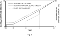
- Fig. 3 is a graph showing a starting-time supply pattern for a resin raw material and that for a filler, stored in the memory unit MEM.
- the horizontal axis indicates time
- the left-side vertical axis indicates the rotation speed of the screw 12.
- the right-side vertical axis indicates the supply amounts of the resin raw material and the filler.
- the rotation speed of the screw 12 is shown as a percentage (%) to the target rotation speed during the manufacturing.
- the supply amounts of the resin raw material and the filler are shown as percentages (%) to the target supply amounts during the manufacturing.
- an operator enters, through the operation panel OP, the target rotation speed of the screw 12 during the manufacturing and the target supply amounts of the resin raw material and the filler.
- the operator may, for example, select them from a list of conditions displayed in the operation panel OP instead of entering them.
- the operator selects a resin raw material as the type of raw material and also selects the hopper 13 as the supply position thereof. Further, the operator also selects a filler as a type of another raw material and selects the side supply port 14 as the supply position thereof.
- the controller CNT reads out the starting-time supply patterns for the resin raw material and for the filler shown in Fig. 3 from the memory unit MEM based on the above-described input information received from the operation panel OP.
- the controller CNT controls the rotation speed of the screw 12 so that the screw 12 rotates according to a rotation speed curve for the screw 12 shown by a broken line in Fig. 3 . Further, the controller CNT controls the resin raw material feeder F1 so that the resin raw material is supplied according to a resin raw material supply amount curve shown by a solid line in Fig. 3 . Further, the controller CNT controls the filler feeder F2 so that the filler is supplied according to a filler supply amount curve shown by a dash-dot line in Fig. 3 .
- the rotation speed of the screw 12 is gradually increased, and the supply amount of the resin raw material is increased with the increase in the rotation speed. Note that as shown in Fig. 3 , at the time t2, the ratio of the supply amount of the resin raw material to the rotation speed of the screw 12 is smaller than the ratio during the manufacturing. Then, toward a starting completion time t5, the ratio of the supply amount of the resin raw material to the rotation speed of the screw 12 is gradually changed so as to approach the ratio during the manufacturing.
- the supply of the filler is started, and the supply amount of the filler is increased with the increase in the rotation speed of the screw 12.
- the ratio of the supply amount of the filler to the supply amount of the resin raw material is smaller than the ratio during the manufacturing. Since the ratio of the supply of the filler is lower than that during the manufacturing as described above, even if the kneading state inside the extruder 10 becomes unstable when the supply amounts of the resin raw material and the filler are being increased, it is possible to prevent these materials from being not able to be extruded from the inside of the extruder 10. As a result, the extruder 10 can be started in a shorter time.
- the ratio of the supply amount of the filler to the supply amount of the resin raw material is increased to the ratio during the manufacturing, and then the ratio is maintained constant until the staring completion time t5.
- the extruder 10 when the extruder 10 is started in order to manufacture a resin compound, after the supplying of the resin raw material is started, the supply of the filler is started after the resin raw material is sufficiently charged into the cylinder 11. Therefore, the filler is never supplied in the state where there is not a sufficient amount of resin raw material in the extruder 10, so that it is possible prevent the extruder 10 from breaking down.
- control method shown in Fig. 3 is not limited to control methods in which the time is monitored, and the rotation speed of the screw 12 and the supply amounts of the resin raw material and the filler are changed at a predetermined timing.
- control method may be one in which the rotation speed of the screw is monitored instead of monitoring the time, and the supply amounts of the resin raw material and the filler are changed when the rotation speed of the screw 12 reaches a predetermined rotation speed.
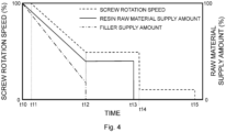
- Fig. 4 is a graph showing a stopping-time supply pattern for a resin raw material and that for a filler, stored in the memory unit MEM.
- the horizontal axis indicates time
- the left-side vertical axis indicates the rotation speed of the screw 12.
- the right-side vertical axis indicates the supply amounts of the resin raw material and the filler.
- the rotation speed of the screw 12 is shown as a percentage (%) to the rotation speed at the moment when the stopping operation is started.
- the supply amounts of the resin raw material and the filler are shown as percentages (%) to the supply amounts at the moment when the stopping operation is started.
- stopping operation is typically started during the manufacturing, but the start of the stopping operation is not limited to any particular timings.
- the stopping operation can be started during the starting operation.
- the controller CNT reads out the stopping-time supply patterns for the resin raw material and for the filler shown in Fig. 4 from the memory unit MEM based on the input information received from the operation panel OP.
- the controller CNT controls the rotation speed of the screw 12 so that the screw 12 rotates according to a rotation speed curve for the screw 12 shown by a broken line in Fig. 4 .
- the controller CNT controls the resin raw material feeder F1 so that the resin raw material is supplied according to a resin raw material supply amount curve shown by a solid line in Fig. 4 .
- the controller CNT controls the filler feeder F2 so that the filler is supplied according to a filler supply amount curve shown by a dash-dot line in Fig. 4 .
- the supply amounts of the resin raw material and the filler are started to be gradually reduced while maintaining the rotation speed of the screw 12 constant. Note that if the rotation speed of the screw 12 is lowered first, there is a possibility that the ratios of the supply amounts of the resin raw material and the filler to the rotation speed of the screw 12 becomes so high that they may not be extruded.
- the rotation speed of the screw 12 is gradually lowered, and the supply amounts of the resin raw material and the filler are reduced with the decrease in the rotation speed.
- the ratios of the supply amounts of the resin raw material and the filler to the rotation speed of the screw 12 is smaller than the ratio during the manufacturing.
- the ratio of the supply amount of the filler to the supply amount of the resin raw material is gradually reduced.
- the content of the filler in the molten resin raw material gradually decreases and the viscosity of the molten resin raw material gradually decreases, so that the stopping operation is stabilized.
- the supply amount of the filler is sharply reduced, there is a possibility that the resin having high viscosity present on the downstream side becomes unable to be extruded by the resin having low viscosity present on the upstream side.
- the rotation speed of the screw 12 is maintained constant during a period from the time t14 to a stopping completion time t15, and the resin raw material remaining inside the cylinder 11 is discharged. It is preferred that the amount of the resin raw material remaining in the cylinder 11 be as small as possible.
- a method for controlling the kneading extrusion apparatus when the interior of the cylinder 11 of the extruder 10 is cleaned will be described with reference to Fig. 5 .
- a cleaning operation is performed before the extruder 10 is started in order to manufacture a resin compound.
- Fig. 5 is a graph showing a cleaning-time supply pattern for a resin raw material, stored in the memory unit MEM.
- the horizontal axis indicates time
- the left-side vertical axis indicates the rotation speed of the screw 12.
- the right-side vertical axis indicates the supply amount of the resin raw material.
- the controller CNT reads out the cleaning-time supply pattern for the resin raw material shown in Fig. 5 from the memory unit MEM.
- the controller CNT controls the rotation speed of the screw 12 so that the screw 12 rotates according to the rotation speed curve for the screw 12 shown by a broken line in Fig. 5 .
- the controller CNT controls the resin raw material feeder F1 so that the resin raw material is supplied according to a resin raw material supply amount curve shown by a solid line in Fig. 5 .
- Fig. 5 during the cleaning, only the resin raw material is supplied into the cylinder 11 and the filler is not supplied into the cylinder 11.
- the rotation of the screw 12 is started, and at a time t21, the rotation speed of the screw 12 is increased.
- the rotation speed which has been increased at the time t21, is such a rotation speed that even when there is no resin raw material inside the cylinder 11, any abnormality such as wear does not occur in the cylinder 11 and the screw 12.
- the rotation speed of the screw 12 is maintained constant during a period from the time t21 to a time t23.
- the rotation speed of the screw 12 and the supply amount of the resin raw material are maintained constant so that the resin raw material is sufficiently charged into the cylinder 11. That is, a charging operation is performed during the period from the time t22 to the time t23.
- a cleaning operation is performed by maintaining the rotation speed of the screw 12 and the supply amount of the resin raw material constant.
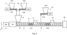
- Fig. 6 is a schematic cross-sectional diagram showing the overall configuration of the kneading extrusion apparatus according to the second embodiment.
- Fig. 6 corresponds to Fig. 1 .
- the kneading extrusion apparatus includes an additive feeder F3 in addition to the resin raw material feeder F1, the filler feeder F2, the extruder 10, and the die 20 shown in Fig. 1 .
- the additive feeder (third feeder) F3 is a feeder for supplying an additive(s), which is one of the components constituting the resin compound, into the cylinder 11 of the extruder 10.
- the additive feeder F3 shown in Fig. 6 is a screw-type feeder and includes a feeder hopper FH3, a feeder screw FS3, and a feeder motor FM3.
- the additive is not limited to any particular additives, and is, for example, an antioxidant, a flame retardant, a crosslinking agent, or the like. Note that the additive may include a resin raw material of which the ratio of the supply is low.
- An additive(s) is charged into the feeder hopper FH3 and stored therein.
- the additive stored in the feeder hopper FH3 is supplied, together with the resin raw material, into the cylinder 11 through a hopper 13 of the extruder 10.
- the supply amount of the additive from the additive feeder F3 to the extruder 10 is controlled by the controller CNT shown in Fig. 7 .
- the additive feeder F3 shown in Fig. 6 is a screw-type feeder, a vibration-type feeder or any of other types of feeders may be used as long as the supply amount of the additive can be controlled by the controller CNT, i.e., by a computer.
- the rest of the configuration is similar to that of the kneading extrusion apparatus according to the first embodiment, and therefore the description thereof will be omitted.
- Fig. 7 is a control block diagram of the kneading extrusion apparatus according to the second embodiment.
- Fig. 7 corresponds to Fig. 2 .
- the kneading extrusion apparatus includes a controller CNT and an operation panel OP.
- the controller CNT controls an additive feeder F3 in addition to the extruder 10, the resin raw material feeder F1, and the filler feeder F2.
- controller CNT controls the rotation speed of the screw 12. Further, the controller CNT controls the supply amount of the additive from the additive feeder F3 in addition to the supply amount of the resin raw material from the resin raw material feeder F 1 and the supply amount of the filler from the filler feeder F2.
- the controller CNT includes a memory unit MEM.
- a starting-time supply pattern for the resin raw material, that for the filler, and that for the additive, which are used when the extruder 10 is started in order to manufacture a resin compound are stored.
- Each of the starting-time supply patterns for the resin raw material, the filler, and the additive is determined in advance.
- a stopping-time supply pattern for the resin raw material, that for the filler, and that for the additive, which are used when the extruder 10 is stopped are stored.
- Each of the stopping-time supply patterns for the resin raw material, the filler, and the additive is determined in advance.
- a cleaning-time supply pattern for the resin raw material for supplying the resin raw material when the interior of the cylinder 11 of the extruder 10 is cleaned is stored.
- the cleaning-time supply pattern for the resin raw material is determined in advance.
- the operation panel OP is an input device by which an operator operates the kneading extrusion apparatus. The operator enters, through the operation panel OP, the supply amount of the additive in addition to the rotation speed of the screw 12 during the manufacturing and the supply amounts of the resin raw material and the filler. Further, the operator selects the type of the raw material and the supply position thereof (the hopper 13 or the side supply port 14).
- the resin raw material is selected as the type of the raw material and the hopper 13 is selected as the supply position.
- the filler is selected as the type of another raw material and the side supply port 14 is selected as the supply position.
- the operator selects an additive(s) as a type of another raw material and also selects the hopper 13 as the supply position.
- the rest of the configuration is similar to that of the kneading extrusion apparatus according to the first embodiment, and therefore the description thereof will be omitted.
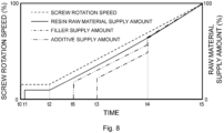
- Fig. 8 is a graph showing a starting-time supply pattern for a resin raw material, that for a filler, and that for an additive, stored in the memory unit MEM.
- Fig. 8 shows a graph corresponding to that shown in Fig. 3 .
- the horizontal axis indicates time
- the left-side vertical axis indicates the rotation speed of the screw 12.
- the right-side vertical axis indicates the supply amounts of the resin raw material, the filler, and the additive.
- the rotation speed of the screw 12 is shown as a percentage (%) to the target rotation speed during the manufacturing.
- the supply amounts of the resin raw material, the filler, and the additive are shown as percentages (%) to the target supply amounts during the manufacturing.
- an operator enters, through the operation panel OP, the target rotation speed of the screw 12 during the manufacturing and the target supply amounts of the resin raw material, the filler, and the additive.
- the operator may, for example, select them from a list of conditions displayed in the operation panel OP instead of entering them.
- the operator selects a resin raw material as the type of raw material and also selects the hopper 13 as the supply position thereof. Further, the operator also selects a filler as a type of another raw material and selects the side supply port 14 as the supply position thereof. Further, the operator selects an additive(s) as a type of another raw material and also selects the hopper 13 as the supply position thereof.
- the controller CNT reads out the starting-time supply patterns for the resin raw material, the filler, and the additive shown in Fig. 8 from the memory unit MEM based on the above-described input information received from the operation panel OP.
- the curve for the rotation speed of the screw 12 shown by a broken line in Fig. 8 is the same as the curve shown in Fig. 3 .
- the controller CNT controls the rotation speed of the screw 12 so that the screw 12 rotates according to the curve.
- the curve for the supply amount of the resin raw material shown by a solid line in Fig. 8 is the same as the curve shown in Fig. 3 .
- the controller CNT controls the resin raw material feeder F1 so that the resin raw material is supplied according to the curve.
- the curve for the supply amount of the filler shown by a dash-dot line in Fig. 8 is the same as the curve shown in Fig. 3 .
- the controller CNT controls the filler feeder F2 so that the filler is supplied according to the curve.
- the controller CNT controls the additive feeder F3 so that the additive is supplied according to the curve for the supply amount of the additive shown by a dash-dot-dot line in Fig. 8 .
- a period from a time t0 to a time t2 is similar to that in Fig. 3 , and therefore the description thereof will be omitted.
- the supply of the additive is started at a time t6, which is later than the time t2 at which the supply of the resin raw material is started and earlier than the time t3 at which the supply of the filler is started, and the supply amount of the additive is increased with the increase in the rotation speed of the screw 12.
- the ratio of the supply amount of the additive to the supply amount of the resin raw material is smaller than the ratio during the manufacturing.
- the supply of the filler is started, and the supply amount of the filler is increased with the increase in the rotation speed of the screw 12.
- the ratios of the supply amounts of the filler and the additive to the supply amount of the resin raw material are smaller than the ratios during the manufacturing. Since the ratio of the supply of the filler is lower than that during the manufacturing as described above, even if the kneading state inside the extruder 10 becomes unstable when the supply amounts of the resin raw material and the filler are being increased, it is possible to prevent these materials from being not able to be extruded from the inside of the extruder 10. As a result, the extruder 10 can be started in a shorter time.
- the ratios of the supply amounts of the filler and the additive to the supply amount of the resin raw material are increased to the ratios during the manufacturing, and then the ratios are maintained constant until the staring completion time t5.
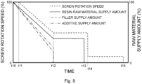
- Fig. 9 is a graph showing a stopping-time supply pattern for a resin raw material, that for a filler, and that for an additive, stored in the memory unit MEM.
- Fig. 9 corresponds to Fig. 4 .
- the horizontal axis indicates time
- the left-side vertical axis indicates the rotation speed of the screw 12.
- the right-side vertical axis indicates the supply amounts of the resin raw material, the filler, and the additive.
- the rotation speed of the screw 12 is shown as a percentage (%) to the rotation speed at the moment when the stopping operation is started.
- the supply amounts of the resin raw material, the filler, and the additive are shown as percentages (%) to the supply amounts at the moment when the stopping operation is started.
- the controller CNT reads out the stopping-time supply patterns for the resin raw material, for the filler, and for the additive shown in Fig. 9 from the memory unit MEM based on the input information received from the operation panel OP.
- the curve for the rotation speed of the screw 12 shown by a broken line in Fig. 9 is the same as the curve shown in Fig. 4 .
- the controller CNT controls the rotation speed of the screw 12 so that the screw 12 rotates according to the curve.
- the curve for the supply amount of the resin raw material shown by a solid line in Fig. 9 is the same as the curve shown in Fig. 4 .
- the controller CNT controls the resin raw material feeder F1 so that the resin raw material is supplied according to the curve.
- the curve for the supply amount of the filler shown by a dash-dot line in Fig. 9 is the same as the curve shown in Fig. 4 .
- the controller CNT controls the filler feeder F2 so that the filler is supplied according to the curve.
- the controller CNT controls the additive feeder F3 so that the additive is supplied according to the curve for the supply amount of the additive shown by a dash-dot-dot line in Fig. 9 .
- the amounts of the resin raw material, the filler, and the additive are started to be gradually reduced while maintaining the rotation speed of the screw 12 constant. Note that if the rotation speed of the screw 12 is lowered first, there is a possibility that the ratios of the supply amounts of the resin raw material, the filler, and the additive to the rotation speed of the screw 12 becomes so high that they may not be extruded.
- the rotation speed of the screw 12 is gradually lowered, and the supply amounts of the resin raw material, the filler, and the additive are also reduced with the decrease in the rotation speed.
- the ratios of the supply amounts of the resin raw material, the filler, and the additive to the rotation speed of the screw 12 is smaller than the ratio during the manufacturing.
- the ratios of the supply amounts of the filler and the additive to the supply amount of the resin raw material is gradually reduced.
- the content of the filler in the molten resin raw material gradually decreases and the viscosity of the molten resin raw material gradually decreases, so that the stopping operation is stabilized. For example, if the supply amount of the filler is sharply reduced, a part of the resin having high viscosity present on the downstream side becomes unable to be extruded due to the presence of a part of the resin having low viscosity present on the upstream side.
- the supply of the additive in addition to the filler is also stopped.
- the rotation speed and the supply amounts at and after the time t12 are similar to those in Fig. 4 , and therefore the descriptions thereof will be omitted.
- the method for controlling the kneading extrusion apparatus when the interior of the cylinder 11 of the extruder 10 is cleaned is similar to that in the first embodiment, and therefore the description thereof will be omitted.
- Fig. 10 is a schematic cross-sectional diagram showing the overall configuration of the kneading extrusion apparatus according to the third embodiment.
- Fig. 10 corresponds to Figs. 1 and 6 .
- the kneading extrusion apparatus includes a liquid feeder F4 in addition to the resin raw material feeder F1, the filler feeder F2, the additive feeder F3, the extruder 10, and the die 20 shown in Fig. 6 .
- the liquid feeder F4 is a feeder for supplying a liquid raw material into the cylinder 11 of the extruder 10.
- the liquid feeder F4 shown in Fig. 10 is a pump-type feeder, and includes a feeder hopper FH4 and a pump P.
- the liquid raw material is not limited to any particular liquid materials, and may be processing oil, alcohol, water, or the like.
- the liquid raw material is charged into the feeder hopper FH4 and stored therein.
- the liquid raw material stored in the feeder hopper FH4 is charged into the cylinder 11 through a nozzle 15 provided in the cylinder 11.
- the supply amount of the additive from the additive feeder F3 to the extruder 10 is controlled by the controller CNT shown in Fig. 11 .
- the additive feeder F3 shown in Fig. 10 is a pump-type one, any of other types of feeders may be used as long as the supply amount of the additive can be controlled by the controller CNT, i.e., by a computer.
- the rest of the configuration is similar to that of the kneading extrusion apparatus according to the second embodiment, and therefore the description thereof will be omitted.
- Fig. 11 is a control block diagram of the kneading extrusion apparatus according to the third embodiment.
- Fig. 11 corresponds to Figs. 2 and 7 .
- the kneading extrusion apparatus includes a controller CNT and an operation panel OP.
- the controller CNT controls a liquid feeder F4 in addition to the extruder 10, the resin raw material feeder F1, the filler feeder F2, and the additive feeder F3.
- controller CNT controls the rotation speed of the screw 12. Further, the controller CNT controls the supply amount of the liquid raw material from the liquid feeder F4 in addition to the supply amount of the resin raw material from the resin raw material feeder F1, the supply amount of the filler from the filler feeder F2, and the supply amount of the additive from the additive feeder F3.
- the controller CNT includes a memory unit MEM.
- a starting-time supply pattern for the resin raw material, that for the filler, that for the additive, and that for the liquid raw material, which are used when the extruder 10 is started in order to manufacture a resin compound are stored.
- Each of the starting-time supply patterns for the resin raw material, the filler, the additive, and the liquid raw material is determined in advance.
- the starting-time supply pattern for the liquid raw material is not shown in the drawings, but it will be briefly described hereinafter with reference to Fig. 8 .
- the supply of the liquid raw material is started at a timing that is later than the time t6 at which the supply of the additive is started and earlier than the time t3 at which the supply of the filler is started. Then, the supply amount of the liquid raw material is increased with the increase in the rotation speed of the screw 12.
- a stopping-time supply pattern for the resin raw material, that for the filler, that for the additive, and that for the liquid raw material, which are used when the extruder 10 is stopped are stored.
- Each of the stopping-time supply patterns for the resin raw material, the filler, the additive, and the liquid raw material is determined in advance.
- the stopping-time supply pattern for the liquid raw material is not shown in the drawings, but it will be briefly described hereinafter with reference to Fig. 9 .
- the amount of the liquid raw material as well as those of the resin raw material, the filler, and the additive are started to be gradually reduced while maintaining the rotation speed of the screw 12 constant. Then, at a time t12, the supply of the liquid raw material is stopped together with those of the filler and the additive.
- a cleaning-time supply pattern for the resin raw material for supplying the resin raw material when the interior of the cylinder 11 of the extruder 10 is cleaned is stored.
- the cleaning-time supply pattern for the resin raw material is determined in advance.
- the operation panel OP is an input device by which an operator operates the kneading extrusion apparatus.
- the operator enters, through the operation panel OP, the supply amount of the liquid raw material in addition to the rotation speed of the screw 12 during the manufacturing, and the supply amounts of the resin raw material, the filler, and the additive. Further, the operator selects the type of the raw material and the supply position thereof (the hopper 13, the side supply port 14, or the nozzle 15).
- the resin raw material is selected as the type of the raw material and the hopper 13 is selected as the supply position.
- the filler is selected as the type of another raw material and the side supply port 14 is selected as the supply position.
- the operator selects an additive(s) as a type of another raw material and also selects the hopper 13 as the supply position.
- the operator selects a liquid raw material as a type of raw material and also selects the nozzle 15 as the supply position.
- the rest of the configuration is similar to that of the kneading extrusion apparatus according to the second embodiment, and therefore the description thereof will be omitted.
- the program includes a set of instructions (or software codes) that, when read into a computer, causes the computer to perform one or more of the functions described in the example embodiments.
- the program may be stored in a non-transitory computer readable medium or in a physical storage medium.
- a computer readable medium or a physical storage medium may include a random-access memory (RAM), a read-only memory (ROM), a flash memory, a solid-state drive (SSD), or other memory technology, a CD-ROM, a digital versatile disc (DVD), a Blu-ray (Registered Trademark) disc or other optical disc storages, a magnetic cassette, magnetic tape, and a magnetic disc storage or other magnetic storage devices.
- the program may be transmitted on a transitory computer readable medium or a communication medium.
- the transitory computer readable medium or the communication medium may include electrical, optical, acoustic, or other forms of propagating signals.
Landscapes
- Engineering & Computer Science (AREA)
- Mechanical Engineering (AREA)
- Extrusion Moulding Of Plastics Or The Like (AREA)
- Processing And Handling Of Plastics And Other Materials For Molding In General (AREA)
Abstract
Description
- The present invention relates to a kneading extrusion apparatus, its control method, and a method for manufacturing a resin compound.
- As shown in Patent Literature 1, the inventors have previously developed a method for automatically controlling an extruder when the extruder is started in a kneading extrusion apparatus.
- Patent Literature 1:
Japanese Unexamined Patent Application Publication No. 2019-69585 - The inventors have examined automatic control for an extruder in a kneading extrusion apparatus that is performed when the extruder is started or stopped.
- The inventors have found that the following problem occurs when a resin compound containing a filler as well as a resin raw material is manufactured by using a kneading extrusion apparatus.
- Since the filler does not melt inside the extruder, its flowability inside the extruder is low. Therefore, if the filler is supplied to the extruder in a state where there is no resin raw material inside the extruder, there is a risk that the extruder could break down, so it is necessary to be particularly careful in performing the automatic control when the extruder is started or stopped.
- Other problems to be solved and new features will become apparent from the following specification and the attached drawings.
- In a kneading extrusion apparatus according to an embodiment, when an extruder is started in order to manufacture a resin compound, an amount of a resin raw material to be supplied is increased with an increase in a rotation speed of a screw of the extruder based on a predetermined starting-time supply pattern for the resin raw material, and based on a predetermined starting-time supply pattern for a filler, a supply of the filler is started after the supplying of the resin raw material is started, and an amount of the filler to be supplied is increased with the increase in the rotation speed of the screw.
- In a kneading extrusion apparatus according to an embodiment, when an extruder is stopped, an amount of a resin raw material to be supplied is reduced with a decrease in a rotation speed of a screw of the extruder based on a predetermined stopping-time supply pattern for the resin raw material, and based on a predetermined stopping-time supply pattern for a filler, an amount of the filler to be supplied is reduced with the increase in the rotation speed of the screw, and the supply of the filler is stopped before the supplying of the resin raw material is stopped.
- According to the above-described embodiment, it is possible to provide an excellent kneading extrusion apparatus.
-
-
Fig. 1 is a schematic cross-sectional diagram showing an overall configuration of a kneading extrusion apparatus according to a first embodiment; -
Fig. 2 is a control block diagram of the kneading extrusion apparatus according to the first embodiment; -
Fig. 3 is a graph showing a starting-time supply pattern for a resin raw material and that of a filler, stored in a storage unit MEM; -
Fig. 4 is a graph showing a stopping-time supply pattern for the resin raw material and that for the filler, stored in the storage unit MEM; -
Fig. 5 is a graph showing a cleaning-time supply pattern for the resin raw material, stored in the storage unit MEM; -
Fig. 6 is a schematic cross-sectional diagram showing an overall configuration of a kneading extrusion apparatus according to a second embodiment; -
Fig. 7 is a control block diagram of the kneading extrusion apparatus according to the second embodiment; -
Fig. 8 is a graph showing starting-time supply patterns for a resin raw material, a filler, and an additive, stored in a storage unit MEM; -
Fig. 9 is a graph showing stopping-time supply patterns for the resin raw materials, the filler, and the additive, stored in the storage unit MEM; -
Fig. 10 is a schematic cross-sectional diagram showing an overall configuration of a kneading extrusion apparatus according to a third embodiment; and -
Fig. 11 is a control block diagram of the kneading extrusion apparatus according to the third embodiment. - Specific embodiments will be described hereinafter in detail with reference to the drawings. However, the present disclosure is not limited to the following embodiments. Further, the following description and drawings are simplified as appropriate for clarifying the explanation.
- Firstly, an overall configuration of a kneading extrusion apparatus according to a first embodiment will be described with reference to
Fig. 1. Fig. 1 is a schematic cross-sectional diagram showing the overall configuration of the kneading extrusion apparatus according to the first embodiment. A resin compound containing a filler dispersed in the resin is extruded and molded by using the kneading extrusion apparatus according to this embodiment. The resin compound extruded and molded by the kneading extrusion apparatus according to this embodiment has, for example, a strand-like shape. However, the shape of the extruded and molded resin compound is not limited to any particular shapes, and it may have, for example, a film-like shape. - As shown in
Fig. 1 , the kneading extrusion apparatus according to the first embodiment includes a resin raw material feeder F1, a filler feeder F2, anextruder 10, and adie 20. - Note that, needless to say, right-handed xyz-orthogonal coordinates shown in
Fig. 1 and other drawings are shown just for explaining the positional relationship among the components. In general, the z-axis positive direction is vertically upward and the xy-plane is a horizontal plane, and these directions and the like are the same throughout the drawings. - The resin raw material feeder (first feeder) F1 is a feeder for supplying a resin raw material, which is a main raw material of a resin compound, into the
cylinder 11 of theextruder 10. The resin raw material feeder F1 shown inFig. 1 is a screw-type feeder and includes a feeder hopper FH1, a feeder screw FS1, and a feeder motor FM1. - The resin raw material is not limited to any particular materials, and is, for example, resin pellets or the like made of polypropylene, polyethylene, polyamide, polyethylene terephthalate, or the like.
- The resin raw material is charged into the feeder hopper FH1 and stored therein. When the feeder screw FS1 is rotationally driven by the feeder motor FM1, the resin raw material stored in the feeder hopper FH1 is supplied into the
cylinder 11 through ahopper 13 of theextruder 10. For example, it is possible to control the supply amount of the resin raw material from the resin raw material feeder F1 to theextruder 10 by measuring the change in the mass of the resin raw material in the feeder hopper FH1 and performing feedback control on the rotation of the feeder motor FM1 based on the measured change. - As will be described later in detail, the supply amount of the resin raw material from the resin raw material feeder F1 to the
extruder 10 is controlled by a controller CNT shown inFig. 2 . Although the resin raw material feeder F1 shown inFig. 1 is a screw-type feeder, a vibration-type feeder or any of other type of feeder may be used as long as the supply amount of the resin raw material can be controlled by the controller CNT, i.e., by a computer. - The filler feeder (second feeder) F2 is a feeder for supplying a filler, which is one of the components constituting the resin compound, into the
cylinder 11 of theextruder 10. The filler feeder F2 shown inFig. 1 is a screw-type feeder and includes a feeder hopper FH2, a feeder screw FS2, and a feeder motor FM2. - The filler is not limited to any particular fillers, and is, for example, talc, a calcium carbonate powder, glass fibers, a carbon powder, or the like.
- The filler is charged into the feeder hopper FH2 and stored therein. When the feeder screw FS2 is rotationally driven by the feeder motor FM2, the filler stored in the feeder hopper FH2 is supplied into the
cylinder 11 through aside supply port 14 of theextruder 10. For example, it is possible to control the supply amount of the filler from the filler feeder F2 to theextruder 10 by measuring the change in the mass of the filler in the feeder hopper FH2 and performing feedback control on the rotation of the feeder motor FM2 based on the measured change. - As will be described later in detail, the supply amount of the filler from the filler feeder F2 to the
extruder 10 is controlled by the controller CNT shown inFig. 2 . Although the filler feeder F2 shown inFig. 1 is a screw-type feeder, a vibration-type feeder or any of other types of feeders may be used as long as the supply amount of the filler can be controlled by the controller CNT, i.e., by a computer. - Note that a side feeder may be provided between the filler feeder F2 and the
side supply port 14, and the filler sent from the filler feeder F2 may be charged into theside supply port 14 through the side feeder. Alternatively, the filler may be supplied from the filler feeder F2 into thecylinder 11 through thehopper 13 of theextruder 10 instead of being supplied through theside supply port 14. - The
extruder 10 is a screw extruder. In theextruder 10 shown inFig. 1 , ascrew 12 extending in the x-axis direction is housed inside thecylinder 11 extending in the x-axis direction. The hopper (first supply port) 13 for supplying the resin raw material from the resin raw material feeder F1 into thecylinder 11 is provided above the end part of thecylinder 11 on the upstream side thereof in the extrusion direction (i.e., on the x-axis negative side). The side supply port (second supply port) 14 for supplying the filler from the filler feeder F2 is provided on the side surface of thecylinder 11 on the downstream side in the extrusion direction (i.e., on the x-axis positive side), that is, on thedie 20 side from thehopper 13. In the following description, the upstream side of thecylinder 11 in the extrusion direction is simply referred to as the "upstream side", and the downstream side thereof in the extrusion direction is simply referred to as the "downstream side". - A screw motor SM is connected to the root of the
screw 12 with a reduction gear RG interposed therebetween. The screw motor SM is a driving source for driving thescrew 12. For example, it is possible to control the rotation speed of thescrew 12 by controlling the rotation speed of the screw motor SM. - Note that the
screw 12 may be composed of one screw or a plurality of screws. For example, anextruder 10 including only onescrew 12 is called a single-screw extruder, and anextruder 10 including twoscrews 12 is called a twin-screw extruder. - The resin raw material supplied from the
hopper 13 is conveyed by the screw motor SM from the root of therotating screw 12 to the tip thereof, i.e., from the upstream side to the downstream side. The resin raw material is heated and sheared by therotating screw 12 inside thecylinder 11, so that the resin raw material is melted. - Note that although it is not shown in the drawings, a heater(s) for heating the interior of the
cylinder 11 is provided on the outer peripheral surface of thecylinder 11 over substantially the entire area thereof in the longitudinal direction. - Note that the shearing and melting of the resin raw material supplied from the
hopper 13 are mainly carried out in a kneading zone KZ1 of theextruder 10 shown inFig. 1 . - Further, a vent V1 is provided in the upper surface of the
cylinder 11 on the downstream side near the kneading zone KZ1. For example, air and volatile components contained in the resin raw material are discharged through the vent V1. - On the downstream side of the vent V1, the
side supply port 14 for supplying a filler is provided on the side surface of thecylinder 11. The filler supplied from theside supply port 14 is conveyed to the downstream side together with the molten resin raw material. A kneading zone KZ2 of theextruder 10 is provided on the downstream side of theside supply port 14. In the kneading zone KZ2, the molten resin raw material and the filler are mixed and kneaded, so that the filler is uniformly dispersed in the molten resin raw material. - A vent V2 is provided in the upper surface of the
cylinder 11 on the downstream side near the kneading zone KZ2. The vent V2 is decompressed by, for example, a vacuum pump (not shown). For example, air and volatile components contained in the resin raw material and the filler are further discharged through the vent V2. - Note that the vents V1 and V2 are not indispensable.
- As shown in
Fig. 1 , g is connected to the tip (i.e., the end part on the x-axis positive side) of theextruder 10. The resin raw material and the filler, which have been mixed and kneaded in theextruder 10, are molded into, for example, a strand-like resin compound by thedie 20. That is, a strand-like resin compound is manufactured by the kneading extrusion apparatus according to this embodiment. - Note that, for example, pellets, which are used as a raw material for a resin molded article, are obtained by cutting this strand-like resin compound. Further, the
die 20 is not indispensable. That is, the resin compound may be just extruded without being molded into a resin molded article. - Next, a configuration of a controller of a kneading extrusion apparatus according to this embodiment will be described with reference to
Fig. 2. Fig. 2 is a control block diagram of the kneading extrusion apparatus according to the first embodiment. As shown inFig. 2 , the kneading extrusion apparatus according to the first embodiment includes a controller CNT and an operation panel OP. - As shown in
Fig. 2 , the controller CNT controls theextruder 10, the resin raw material feeder F1, and the filler feeder F2. - More specifically, the controller CNT controls the rotation speed of the
screw 12. In the example shown inFig. 1 , the controller CNT controls the rotation speed of thescrew 12, for example, but not limited to, by controlling the rotation speed of the screw motor SM. Further, the controller CNT controls the supply amount of the resin raw material from the resin raw material feeder F1 and the supply amount of the filler from the filler feeder F2. - Note that as shown in
Fig. 2 , the controller CNT includes a memory unit MEM. - In the memory unit MEM, a starting-time supply pattern for the resin raw material and that for the filler, which are used when the
extruder 10 is started in order to manufacture a resin compound, are stored. Each of the starting-time supply patterns for the resin raw material and for the filler is determined in advance. - Details of the starting-time supply patterns for the resin raw material and for the filler will be described later.
- Further, in the memory unit MEM, a stopping-time supply pattern for the resin raw material and that for the filler, which are used when the
extruder 10 is stopped, are stored. Each of the stopping-time supply patterns for the resin raw material and for the filler is determined in advance. - Details of the stopping-time supply patterns for the resin raw material and for the filler will be described later.
- Note that in the memory unit MEM, at least one of the starting-time supply patterns for the resin raw material and for the filler or the stopping-time supply patterns for the resin raw material and for the filler may be stored.
- Further, in the memory unit MEM, a cleaning-time supply pattern for the resin raw material for supplying the resin raw material when the interior of the
cylinder 11 of theextruder 10 is cleaned is stored. The cleaning-time supply pattern for the resin raw material is determined in advance. For example, after thescrew 12 is replaced in order to change the type of the resin compound to be manufactured, the interior of thecylinder 11 is cleaned before theextruder 10 is started in order to manufacture the resin compound. During the cleaning, only the resin raw material is supplied into thecylinder 11. - Details of the cleaning-time supply pattern for the resin raw material will be described later.
- Note that the controller CNT can be implemented by a CPU (Central Processing Unit) or other circuits in addition to the memory unit MEM when it is implemented by hardware, and can be implemented by a program or the like loaded into the memory unit MEM when it is implemented by software. Therefore, the controller CNT can be implemented in various forms by computer hardware, software, or a combination thereof.
- Further, the memory unit MEM may be provided outside the controller CNT.
- The operation panel OP is an input device by which an operator operates the kneading extrusion apparatus. The operator enters, through the operation panel OP, the rotation speed of the
screw 12 during the manufacturing, and the supply amounts of the resin raw material and the filler. Further, the operator selects the type of the raw material and the supply position (thehopper 13 or the side supply port 14) from which the raw material is supplied. - For example, in the case of the kneading extrusion apparatus according to this embodiment, the resin raw material is selected as the type of the raw material and the
hopper 13 is selected as the supply position. Further, the filler is selected as the type of another raw material and theside supply port 14 is selected as the supply position. - Next, a method for controlling the kneading extrusion apparatus when the
extruder 10 is started in order to manufacture a resin compound will be described with reference toFig. 3 . -
Fig. 3 is a graph showing a starting-time supply pattern for a resin raw material and that for a filler, stored in the memory unit MEM. InFig. 3 , the horizontal axis indicates time, and the left-side vertical axis indicates the rotation speed of thescrew 12. Further, the right-side vertical axis indicates the supply amounts of the resin raw material and the filler. InFig. 3 , the rotation speed of thescrew 12 is shown as a percentage (%) to the target rotation speed during the manufacturing. Similarly, inFig. 3 , the supply amounts of the resin raw material and the filler are shown as percentages (%) to the target supply amounts during the manufacturing. - When the
extruder 10 is started in order to manufacture a resin compound, an operator enters, through the operation panel OP, the target rotation speed of thescrew 12 during the manufacturing and the target supply amounts of the resin raw material and the filler. Note that in the case where the above-described conditions are stored in the memory unit MEM in advance, the operator may, for example, select them from a list of conditions displayed in the operation panel OP instead of entering them. - Further, in the operation panel OP, the operator selects a resin raw material as the type of raw material and also selects the
hopper 13 as the supply position thereof. Further, the operator also selects a filler as a type of another raw material and selects theside supply port 14 as the supply position thereof. - The controller CNT reads out the starting-time supply patterns for the resin raw material and for the filler shown in
Fig. 3 from the memory unit MEM based on the above-described input information received from the operation panel OP. - The controller CNT controls the rotation speed of the
screw 12 so that thescrew 12 rotates according to a rotation speed curve for thescrew 12 shown by a broken line inFig. 3 . Further, the controller CNT controls the resin raw material feeder F1 so that the resin raw material is supplied according to a resin raw material supply amount curve shown by a solid line inFig. 3 . Further, the controller CNT controls the filler feeder F2 so that the filler is supplied according to a filler supply amount curve shown by a dash-dot line inFig. 3 . - Details of a method for controlling the kneading extrusion apparatus when the
extruder 10 is started in order to manufacture a resin compound will be described hereinafter with reference toFig. 3 . - Firstly, after the rotation of the
screw 12 is started at a time t0, the supply of the resin raw material is started at a time t1 while maintaining the rotation speed of thescrew 12 constant. - During a period from the time t1 to a time t2, the rotation speed of the
screw 12 and the supply amount of the resin raw material are maintained constant so that the resin raw material is sufficiently charged into thecylinder 11. - At and after the time t2, the rotation speed of the
screw 12 is gradually increased, and the supply amount of the resin raw material is increased with the increase in the rotation speed. Note that as shown inFig. 3 , at the time t2, the ratio of the supply amount of the resin raw material to the rotation speed of thescrew 12 is smaller than the ratio during the manufacturing. Then, toward a starting completion time t5, the ratio of the supply amount of the resin raw material to the rotation speed of thescrew 12 is gradually changed so as to approach the ratio during the manufacturing. - At a time t3, the supply of the filler is started, and the supply amount of the filler is increased with the increase in the rotation speed of the
screw 12. Note that as shown inFig. 3 , during a period from the time t3 to a time t4, the ratio of the supply amount of the filler to the supply amount of the resin raw material is smaller than the ratio during the manufacturing. Since the ratio of the supply of the filler is lower than that during the manufacturing as described above, even if the kneading state inside theextruder 10 becomes unstable when the supply amounts of the resin raw material and the filler are being increased, it is possible to prevent these materials from being not able to be extruded from the inside of theextruder 10. As a result, theextruder 10 can be started in a shorter time. - At the time t4, the ratio of the supply amount of the filler to the supply amount of the resin raw material is increased to the ratio during the manufacturing, and then the ratio is maintained constant until the staring completion time t5.
- As shown in
Fig. 3 , in the kneading extrusion apparatus according to this embodiment, when theextruder 10 is started in order to manufacture a resin compound, after the supplying of the resin raw material is started, the supply of the filler is started after the resin raw material is sufficiently charged into thecylinder 11. Therefore, the filler is never supplied in the state where there is not a sufficient amount of resin raw material in theextruder 10, so that it is possible prevent theextruder 10 from breaking down. - Note that the control method shown in
Fig. 3 is not limited to control methods in which the time is monitored, and the rotation speed of thescrew 12 and the supply amounts of the resin raw material and the filler are changed at a predetermined timing. For example, the control method may be one in which the rotation speed of the screw is monitored instead of monitoring the time, and the supply amounts of the resin raw material and the filler are changed when the rotation speed of thescrew 12 reaches a predetermined rotation speed. - Next, a method for controlling the kneading extrusion apparatus when the
extruder 10 is stopped will be described with reference toFig. 4 . -
Fig. 4 is a graph showing a stopping-time supply pattern for a resin raw material and that for a filler, stored in the memory unit MEM. InFig. 4 , the horizontal axis indicates time, and the left-side vertical axis indicates the rotation speed of thescrew 12. Further, the right-side vertical axis indicates the supply amounts of the resin raw material and the filler. InFig. 4 , the rotation speed of thescrew 12 is shown as a percentage (%) to the rotation speed at the moment when the stopping operation is started. Similarly, inFig. 3 , the supply amounts of the resin raw material and the filler are shown as percentages (%) to the supply amounts at the moment when the stopping operation is started. - Note that the stopping operation is typically started during the manufacturing, but the start of the stopping operation is not limited to any particular timings. For example, the stopping operation can be started during the starting operation.
- Similarly to the starting operation, the controller CNT reads out the stopping-time supply patterns for the resin raw material and for the filler shown in
Fig. 4 from the memory unit MEM based on the input information received from the operation panel OP. The controller CNT controls the rotation speed of thescrew 12 so that thescrew 12 rotates according to a rotation speed curve for thescrew 12 shown by a broken line inFig. 4 . Further, the controller CNT controls the resin raw material feeder F1 so that the resin raw material is supplied according to a resin raw material supply amount curve shown by a solid line inFig. 4 . Further, the controller CNT controls the filler feeder F2 so that the filler is supplied according to a filler supply amount curve shown by a dash-dot line inFig. 4 . - Details of a method for controlling the kneading extrusion apparatus when the
extruder 10 is stopped will be described hereinafter with reference toFig. 4 . - Firstly, at a time t10, the supply amounts of the resin raw material and the filler are started to be gradually reduced while maintaining the rotation speed of the
screw 12 constant. Note that if the rotation speed of thescrew 12 is lowered first, there is a possibility that the ratios of the supply amounts of the resin raw material and the filler to the rotation speed of thescrew 12 becomes so high that they may not be extruded. - Next, at a time t11, the rotation speed of the
screw 12 is started to be gradually lowered. - During a period from the time t11 to a time t12, the rotation speed of the
screw 12 is gradually lowered, and the supply amounts of the resin raw material and the filler are reduced with the decrease in the rotation speed. During this period, as shown inFig. 4 , the ratios of the supply amounts of the resin raw material and the filler to the rotation speed of thescrew 12 is smaller than the ratio during the manufacturing. - Further, as shown in
Fig. 4 , during this period, the ratio of the supply amount of the filler to the supply amount of the resin raw material is gradually reduced. The content of the filler in the molten resin raw material gradually decreases and the viscosity of the molten resin raw material gradually decreases, so that the stopping operation is stabilized. For example, if the supply amount of the filler is sharply reduced, there is a possibility that the resin having high viscosity present on the downstream side becomes unable to be extruded by the resin having low viscosity present on the upstream side. - At a time t12, the supply of the filler is stopped.
- During a period from the time t12 to a time t13, the rotation speed of the
screw 12 and the supply amount of the resin raw material are maintained constant, and the interior of thecylinder 11 is cleaned by the resin raw material. - At the time t13, the supply of the resin raw material is stopped, and at a time t14, which is slightly later than the time t13, the rotation speed of the
screw 12 is lowered. - The rotation speed of the
screw 12 is maintained constant during a period from the time t14 to a stopping completion time t15, and the resin raw material remaining inside thecylinder 11 is discharged. It is preferred that the amount of the resin raw material remaining in thecylinder 11 be as small as possible. - Then, the rotation of the
screw 12 is stopped at the stopping completion time t15. - As shown in
Fig. 4 , in the kneading extrusion apparatus according to this embodiment, when theextruder 10 is stopped, the supply of the filler is stopped before the supplying of the resin raw material is stopped. Therefore, the filler is never supplied in the state where there is not a sufficient amount of resin raw material in theextruder 10, so that it is possible prevent theextruder 10 from breaking down. - Next, a method for controlling the kneading extrusion apparatus when the interior of the
cylinder 11 of theextruder 10 is cleaned will be described with reference toFig. 5 . For example, a cleaning operation is performed before theextruder 10 is started in order to manufacture a resin compound. -
Fig. 5 is a graph showing a cleaning-time supply pattern for a resin raw material, stored in the memory unit MEM. InFig. 5 , the horizontal axis indicates time, and the left-side vertical axis indicates the rotation speed of thescrew 12. Further, the right-side vertical axis indicates the supply amount of the resin raw material. - For example, when an operator instructs to perform cleaning through the operation panel OP, the controller CNT reads out the cleaning-time supply pattern for the resin raw material shown in
Fig. 5 from the memory unit MEM. The controller CNT controls the rotation speed of thescrew 12 so that thescrew 12 rotates according to the rotation speed curve for thescrew 12 shown by a broken line inFig. 5 . Further, the controller CNT controls the resin raw material feeder F1 so that the resin raw material is supplied according to a resin raw material supply amount curve shown by a solid line inFig. 5 . As shown inFig. 5 , during the cleaning, only the resin raw material is supplied into thecylinder 11 and the filler is not supplied into thecylinder 11. - Details of a method for controlling the kneading extrusion apparatus during the cleaning will be described hereinafter with reference to
Fig. 5 . - Firstly, at a time t20, the rotation of the
screw 12 is started, and at a time t21, the rotation speed of thescrew 12 is increased. The rotation speed, which has been increased at the time t21, is such a rotation speed that even when there is no resin raw material inside thecylinder 11, any abnormality such as wear does not occur in thecylinder 11 and thescrew 12. - The rotation speed of the
screw 12 is maintained constant during a period from the time t21 to a time t23. - At a time t22, the supply of the resin raw material is started.
- During a period from the time t22 to a time t23, the rotation speed of the
screw 12 and the supply amount of the resin raw material are maintained constant so that the resin raw material is sufficiently charged into thecylinder 11. That is, a charging operation is performed during the period from the time t22 to the time t23. - At the time t23, the rotation speed of the
screw 12 is increased, and at a time t24, which is slightly later than the time t23, the supply amount of the resin raw material is increased. - During a period from the time t24 to a time t25, a cleaning operation is performed by maintaining the rotation speed of the
screw 12 and the supply amount of the resin raw material constant. - At the time t25, the supply of the resin raw material is stopped, and at a time t26, which is slightly later than the time t25, the rotation speed of the
screw 12 is lowered. - During a period from the time t26 to a cleaning completion time t27, the rotation speed of the
screw 12 is maintained constant, and a discharging operation for discharging the resin raw material remaining in thecylinder 11 is performed. - Then, the rotation of the
screw 12 is stopped at the cleaning completion time t27. - Next, an overall configuration of a kneading extrusion apparatus according to a second embodiment will be described with reference to
Fig. 6. Fig. 6 is a schematic cross-sectional diagram showing the overall configuration of the kneading extrusion apparatus according to the second embodiment.Fig. 6 corresponds toFig. 1 . - As shown in
Fig. 6 , the kneading extrusion apparatus according to the second embodiment includes an additive feeder F3 in addition to the resin raw material feeder F1, the filler feeder F2, theextruder 10, and the die 20 shown inFig. 1 . - The additive feeder (third feeder) F3 is a feeder for supplying an additive(s), which is one of the components constituting the resin compound, into the
cylinder 11 of theextruder 10. The additive feeder F3 shown inFig. 6 is a screw-type feeder and includes a feeder hopper FH3, a feeder screw FS3, and a feeder motor FM3. - The additive is not limited to any particular additives, and is, for example, an antioxidant, a flame retardant, a crosslinking agent, or the like. Note that the additive may include a resin raw material of which the ratio of the supply is low.
- An additive(s) is charged into the feeder hopper FH3 and stored therein. When the feeder screw FS2 is rotationally driven by the feeder motor FM3, the additive stored in the feeder hopper FH3 is supplied, together with the resin raw material, into the
cylinder 11 through ahopper 13 of theextruder 10. For example, it is possible to control the supply amount of the additive from the additive feeder F3 to theextruder 10 by measuring the change in the mass of the additive in the feeder hopper FH3 and performing feedback control on the rotation of the feeder motor FM3 based on the measured change. - As will be described later in detail, the supply amount of the additive from the additive feeder F3 to the
extruder 10 is controlled by the controller CNT shown inFig. 7 . Although the additive feeder F3 shown inFig. 6 is a screw-type feeder, a vibration-type feeder or any of other types of feeders may be used as long as the supply amount of the additive can be controlled by the controller CNT, i.e., by a computer. - The rest of the configuration is similar to that of the kneading extrusion apparatus according to the first embodiment, and therefore the description thereof will be omitted.
- Next, a configuration of a controller of a kneading extrusion apparatus according to this embodiment will be described with reference to
Fig. 7. Fig. 7 is a control block diagram of the kneading extrusion apparatus according to the second embodiment.Fig. 7 corresponds toFig. 2 . - As shown in
Fig. 7 , the kneading extrusion apparatus according to the second embodiment includes a controller CNT and an operation panel OP. - As shown in
Fig. 7 , the controller CNT controls an additive feeder F3 in addition to theextruder 10, the resin raw material feeder F1, and the filler feeder F2. - More specifically, the controller CNT controls the rotation speed of the
screw 12. Further, the controller CNT controls the supply amount of the additive from the additive feeder F3 in addition to the supply amount of the resin raw material from the resin raw material feeder F 1 and the supply amount of the filler from the filler feeder F2. - Note that as shown in
Fig. 7 , the controller CNT includes a memory unit MEM. - In the memory unit MEM, a starting-time supply pattern for the resin raw material, that for the filler, and that for the additive, which are used when the
extruder 10 is started in order to manufacture a resin compound, are stored. Each of the starting-time supply patterns for the resin raw material, the filler, and the additive is determined in advance. - Details of the starting-time supply patterns for the resin raw material, the filler, and the additive will be described later.
- Further, in the memory unit MEM, a stopping-time supply pattern for the resin raw material, that for the filler, and that for the additive, which are used when the
extruder 10 is stopped, are stored. Each of the stopping-time supply patterns for the resin raw material, the filler, and the additive is determined in advance. - Details of the stopping-time supply patterns for the resin raw material, the filler, and the additive will be described later.
- Further, similarly to the first embodiment, in the memory unit MEM, a cleaning-time supply pattern for the resin raw material for supplying the resin raw material when the interior of the
cylinder 11 of theextruder 10 is cleaned is stored. The cleaning-time supply pattern for the resin raw material is determined in advance. - The operation panel OP is an input device by which an operator operates the kneading extrusion apparatus. The operator enters, through the operation panel OP, the supply amount of the additive in addition to the rotation speed of the
screw 12 during the manufacturing and the supply amounts of the resin raw material and the filler. Further, the operator selects the type of the raw material and the supply position thereof (thehopper 13 or the side supply port 14). - For example, in the case of the kneading extrusion apparatus according to this embodiment, the resin raw material is selected as the type of the raw material and the
hopper 13 is selected as the supply position. Further, the filler is selected as the type of another raw material and theside supply port 14 is selected as the supply position. Further, the operator selects an additive(s) as a type of another raw material and also selects thehopper 13 as the supply position. - The rest of the configuration is similar to that of the kneading extrusion apparatus according to the first embodiment, and therefore the description thereof will be omitted.
- Next, a method for controlling the kneading extrusion apparatus when the
extruder 10 is started in order to manufacture a resin compound will be described with reference toFig. 8 . -
Fig. 8 is a graph showing a starting-time supply pattern for a resin raw material, that for a filler, and that for an additive, stored in the memory unit MEM.Fig. 8 shows a graph corresponding to that shown inFig. 3 . - In
Fig. 8 , the horizontal axis indicates time, and the left-side vertical axis indicates the rotation speed of thescrew 12. Further, the right-side vertical axis indicates the supply amounts of the resin raw material, the filler, and the additive. InFig. 8 , the rotation speed of thescrew 12 is shown as a percentage (%) to the target rotation speed during the manufacturing. Similarly, inFig. 8 , the supply amounts of the resin raw material, the filler, and the additive are shown as percentages (%) to the target supply amounts during the manufacturing. - When the
extruder 10 is started in order to manufacture a resin compound, an operator enters, through the operation panel OP, the target rotation speed of thescrew 12 during the manufacturing and the target supply amounts of the resin raw material, the filler, and the additive. Note that in the case where the above-described conditions are stored in the memory unit MEM in advance, the operator may, for example, select them from a list of conditions displayed in the operation panel OP instead of entering them. - Further, in the operation panel OP, the operator selects a resin raw material as the type of raw material and also selects the
hopper 13 as the supply position thereof. Further, the operator also selects a filler as a type of another raw material and selects theside supply port 14 as the supply position thereof. Further, the operator selects an additive(s) as a type of another raw material and also selects thehopper 13 as the supply position thereof. - The controller CNT reads out the starting-time supply patterns for the resin raw material, the filler, and the additive shown in
Fig. 8 from the memory unit MEM based on the above-described input information received from the operation panel OP. - The curve for the rotation speed of the
screw 12 shown by a broken line inFig. 8 is the same as the curve shown inFig. 3 . The controller CNT controls the rotation speed of thescrew 12 so that thescrew 12 rotates according to the curve. - Further, the curve for the supply amount of the resin raw material shown by a solid line in
Fig. 8 is the same as the curve shown inFig. 3 . The controller CNT controls the resin raw material feeder F1 so that the resin raw material is supplied according to the curve. - Further, the curve for the supply amount of the filler shown by a dash-dot line in
Fig. 8 is the same as the curve shown inFig. 3 . The controller CNT controls the filler feeder F2 so that the filler is supplied according to the curve. - In addition, in this embodiment, the controller CNT controls the additive feeder F3 so that the additive is supplied according to the curve for the supply amount of the additive shown by a dash-dot-dot line in
Fig. 8 . - Details of a method for controlling the kneading extrusion apparatus when the
extruder 10 is started in order to manufacture a resin compound will be described hereinafter with reference toFig. 8 . - A period from a time t0 to a time t2 is similar to that in
Fig. 3 , and therefore the description thereof will be omitted. - In this embodiment, the supply of the additive is started at a time t6, which is later than the time t2 at which the supply of the resin raw material is started and earlier than the time t3 at which the supply of the filler is started, and the supply amount of the additive is increased with the increase in the rotation speed of the
screw 12. Note that as shown inFig. 8 , during a period from the time t6 to the time t4, the ratio of the supply amount of the additive to the supply amount of the resin raw material is smaller than the ratio during the manufacturing. - After the time t6, at the time t3, the supply of the filler is started, and the supply amount of the filler is increased with the increase in the rotation speed of the
screw 12. Note that as shown inFig. 8 , during the period from the time t3 to the time t4, the ratios of the supply amounts of the filler and the additive to the supply amount of the resin raw material are smaller than the ratios during the manufacturing. Since the ratio of the supply of the filler is lower than that during the manufacturing as described above, even if the kneading state inside theextruder 10 becomes unstable when the supply amounts of the resin raw material and the filler are being increased, it is possible to prevent these materials from being not able to be extruded from the inside of theextruder 10. As a result, theextruder 10 can be started in a shorter time. - At the time t4, the ratios of the supply amounts of the filler and the additive to the supply amount of the resin raw material are increased to the ratios during the manufacturing, and then the ratios are maintained constant until the staring completion time t5.
- As shown in
Fig. 8 , even in the kneading extrusion apparatus according to this embodiment, when theextruder 10 is started in order to manufacture a resin compound, after the supplying of the resin raw material is started, the supply of the filler is started after the resin raw material is sufficiently charged into thecylinder 11. Therefore, the filler is never supplied in the state where there is not a sufficient amount of resin raw material in theextruder 10, so that it is possible prevent theextruder 10 from breaking down. - Next, a method for controlling the kneading extrusion apparatus when the
extruder 10 is stopped will be described with reference toFig. 9 . -
Fig. 9 is a graph showing a stopping-time supply pattern for a resin raw material, that for a filler, and that for an additive, stored in the memory unit MEM.Fig. 9 corresponds toFig. 4 . - In
Fig. 9 , the horizontal axis indicates time, and the left-side vertical axis indicates the rotation speed of thescrew 12. Further, the right-side vertical axis indicates the supply amounts of the resin raw material, the filler, and the additive. InFig. 9 , the rotation speed of thescrew 12 is shown as a percentage (%) to the rotation speed at the moment when the stopping operation is started. Similarly, inFig. 9 , the supply amounts of the resin raw material, the filler, and the additive are shown as percentages (%) to the supply amounts at the moment when the stopping operation is started. - Similarly to the starting operation, the controller CNT reads out the stopping-time supply patterns for the resin raw material, for the filler, and for the additive shown in
Fig. 9 from the memory unit MEM based on the input information received from the operation panel OP. - The curve for the rotation speed of the
screw 12 shown by a broken line inFig. 9 is the same as the curve shown inFig. 4 . The controller CNT controls the rotation speed of thescrew 12 so that thescrew 12 rotates according to the curve. - Further, the curve for the supply amount of the resin raw material shown by a solid line in
Fig. 9 is the same as the curve shown inFig. 4 . The controller CNT controls the resin raw material feeder F1 so that the resin raw material is supplied according to the curve. - Further, the curve for the supply amount of the filler shown by a dash-dot line in
Fig. 9 is the same as the curve shown inFig. 4 . The controller CNT controls the filler feeder F2 so that the filler is supplied according to the curve. - In addition, in this embodiment, the controller CNT controls the additive feeder F3 so that the additive is supplied according to the curve for the supply amount of the additive shown by a dash-dot-dot line in
Fig. 9 . - Details of a method for controlling the kneading extrusion apparatus when the
extruder 10 is stopped will be described hereinafter with reference toFig. 9 . - Firstly, at a time t10, the amounts of the resin raw material, the filler, and the additive are started to be gradually reduced while maintaining the rotation speed of the
screw 12 constant. Note that if the rotation speed of thescrew 12 is lowered first, there is a possibility that the ratios of the supply amounts of the resin raw material, the filler, and the additive to the rotation speed of thescrew 12 becomes so high that they may not be extruded. - Next, at a time t11, the rotation speed of the
screw 12 is started to be gradually lowered. - During a period from the time t11 to a time t12, the rotation speed of the
screw 12 is gradually lowered, and the supply amounts of the resin raw material, the filler, and the additive are also reduced with the decrease in the rotation speed. During this period, as shown inFig. 9 , the ratios of the supply amounts of the resin raw material, the filler, and the additive to the rotation speed of thescrew 12 is smaller than the ratio during the manufacturing. - Further, as shown in
Fig. 9 , during this period, the ratios of the supply amounts of the filler and the additive to the supply amount of the resin raw material is gradually reduced. The content of the filler in the molten resin raw material gradually decreases and the viscosity of the molten resin raw material gradually decreases, so that the stopping operation is stabilized. For example, if the supply amount of the filler is sharply reduced, a part of the resin having high viscosity present on the downstream side becomes unable to be extruded due to the presence of a part of the resin having low viscosity present on the upstream side. - At a time t12, the supply of the additive in addition to the filler is also stopped. The rotation speed and the supply amounts at and after the time t12 are similar to those in
Fig. 4 , and therefore the descriptions thereof will be omitted. - As shown in
Fig. 9 , even in the kneading extrusion apparatus according to this embodiment, when theextruder 10 is stopped, the supply of the filler is stopped before the supplying of the resin raw material is stopped. Therefore, the filler is never supplied in the state where there is not a sufficient amount of resin raw material in theextruder 10, so that it is possible prevent theextruder 10 from breaking down. - The method for controlling the kneading extrusion apparatus when the interior of the
cylinder 11 of theextruder 10 is cleaned is similar to that in the first embodiment, and therefore the description thereof will be omitted. - Next, an overall configuration of a kneading extrusion apparatus according to a third embodiment will be described with reference to
Fig. 10. Fig. 10 is a schematic cross-sectional diagram showing the overall configuration of the kneading extrusion apparatus according to the third embodiment.Fig. 10 corresponds toFigs. 1 and6 . - As shown in
Fig. 10 , the kneading extrusion apparatus according to the third embodiment includes a liquid feeder F4 in addition to the resin raw material feeder F1, the filler feeder F2, the additive feeder F3, theextruder 10, and the die 20 shown inFig. 6 . - The liquid feeder F4 is a feeder for supplying a liquid raw material into the
cylinder 11 of theextruder 10. The liquid feeder F4 shown inFig. 10 is a pump-type feeder, and includes a feeder hopper FH4 and a pump P. - The liquid raw material is not limited to any particular liquid materials, and may be processing oil, alcohol, water, or the like.
- The liquid raw material is charged into the feeder hopper FH4 and stored therein. When the pump P is driven, the liquid raw material stored in the feeder hopper FH4 is charged into the
cylinder 11 through anozzle 15 provided in thecylinder 11. For example, it is possible to control the supply amount of the liquid raw material from the liquid feeder F4 to theextruder 10 by measuring the change in the mass of the liquid raw material in the feeder hopper FH4 and performing feedback control on the pump P based on the measured change. - As will be described later in detail, the supply amount of the additive from the additive feeder F3 to the
extruder 10 is controlled by the controller CNT shown inFig. 11 . Although the additive feeder F3 shown inFig. 10 is a pump-type one, any of other types of feeders may be used as long as the supply amount of the additive can be controlled by the controller CNT, i.e., by a computer. - The rest of the configuration is similar to that of the kneading extrusion apparatus according to the second embodiment, and therefore the description thereof will be omitted.
- <Configuration of Controller of Kneading Extrusion Apparatus>
- Next, a configuration of a controller of a kneading extrusion apparatus according to this embodiment will be described with reference to
Fig. 11. Fig. 11 is a control block diagram of the kneading extrusion apparatus according to the third embodiment.Fig. 11 corresponds toFigs. 2 and7 . - As shown in
Fig. 11 , the kneading extrusion apparatus according to the third embodiment includes a controller CNT and an operation panel OP. - As shown in
Fig. 11 , the controller CNT controls a liquid feeder F4 in addition to theextruder 10, the resin raw material feeder F1, the filler feeder F2, and the additive feeder F3. - More specifically, the controller CNT controls the rotation speed of the
screw 12. Further, the controller CNT controls the supply amount of the liquid raw material from the liquid feeder F4 in addition to the supply amount of the resin raw material from the resin raw material feeder F1, the supply amount of the filler from the filler feeder F2, and the supply amount of the additive from the additive feeder F3. - Note that as shown in
Fig. 11 , the controller CNT includes a memory unit MEM. - In the memory unit MEM, a starting-time supply pattern for the resin raw material, that for the filler, that for the additive, and that for the liquid raw material, which are used when the
extruder 10 is started in order to manufacture a resin compound, are stored. Each of the starting-time supply patterns for the resin raw material, the filler, the additive, and the liquid raw material is determined in advance. - The starting-time supply pattern for the liquid raw material is not shown in the drawings, but it will be briefly described hereinafter with reference to
Fig. 8 . - For example, in
Fig. 8 , the supply of the liquid raw material is started at a timing that is later than the time t6 at which the supply of the additive is started and earlier than the time t3 at which the supply of the filler is started. Then, the supply amount of the liquid raw material is increased with the increase in the rotation speed of thescrew 12. - Further, in the memory unit MEM, a stopping-time supply pattern for the resin raw material, that for the filler, that for the additive, and that for the liquid raw material, which are used when the
extruder 10 is stopped, are stored. Each of the stopping-time supply patterns for the resin raw material, the filler, the additive, and the liquid raw material is determined in advance. - The stopping-time supply pattern for the liquid raw material is not shown in the drawings, but it will be briefly described hereinafter with reference to
Fig. 9 . - For example, at a time t10 in
Fig. 9 , the amount of the liquid raw material as well as those of the resin raw material, the filler, and the additive are started to be gradually reduced while maintaining the rotation speed of thescrew 12 constant. Then, at a time t12, the supply of the liquid raw material is stopped together with those of the filler and the additive. - Further, similarly to the first embodiment, in the memory unit MEM, a cleaning-time supply pattern for the resin raw material for supplying the resin raw material when the interior of the
cylinder 11 of theextruder 10 is cleaned is stored. The cleaning-time supply pattern for the resin raw material is determined in advance. - The operation panel OP is an input device by which an operator operates the kneading extrusion apparatus. The operator enters, through the operation panel OP, the supply amount of the liquid raw material in addition to the rotation speed of the
screw 12 during the manufacturing, and the supply amounts of the resin raw material, the filler, and the additive. Further, the operator selects the type of the raw material and the supply position thereof (thehopper 13, theside supply port 14, or the nozzle 15). - For example, in the case of the kneading extrusion apparatus according to this embodiment, the resin raw material is selected as the type of the raw material and the
hopper 13 is selected as the supply position. Further, the filler is selected as the type of another raw material and theside supply port 14 is selected as the supply position. Further, the operator selects an additive(s) as a type of another raw material and also selects thehopper 13 as the supply position. Further, the operator selects a liquid raw material as a type of raw material and also selects thenozzle 15 as the supply position. - The rest of the configuration is similar to that of the kneading extrusion apparatus according to the second embodiment, and therefore the description thereof will be omitted.
- In the above-described examples, the program includes a set of instructions (or software codes) that, when read into a computer, causes the computer to perform one or more of the functions described in the example embodiments. The program may be stored in a non-transitory computer readable medium or in a physical storage medium. By way of example rather than limitation, a computer readable medium or a physical storage medium may include a random-access memory (RAM), a read-only memory (ROM), a flash memory, a solid-state drive (SSD), or other memory technology, a CD-ROM, a digital versatile disc (DVD), a Blu-ray (Registered Trademark) disc or other optical disc storages, a magnetic cassette, magnetic tape, and a magnetic disc storage or other magnetic storage devices. The program may be transmitted on a transitory computer readable medium or a communication medium. By way of example rather than limitation, the transitory computer readable medium or the communication medium may include electrical, optical, acoustic, or other forms of propagating signals.
- The invention made by the inventors of the present application has been described above in a concrete manner based on embodiments. However, the present invention is not limited to the above-described embodiments, and needless to say, various modifications can be made without departing from the spirit and scope of the invention.
- This application is based upon and claims the benefit of priority from
Japanese patent application No. 2021-176036, filed on October 28, 2021 -
- 10
- EXTRUDER
- 11
- CYLINDER
- 12
- SCREW
- 13
- HOPPER
- 14
- SIDE SUPPLY PORT
- 15
- NOZZLE
- 20
- DIE
- CNT
- CONTROLLER
- F1
- RESIN RAW MATERIAL FEEDER
- F2
- FILLER FEEDER
- F3
- ADDITIVE FEEDER
- F4
- LIQUID FEEDER
- FH1-FH4
- FEEDER HOPPER
- FM1-FM3
- FEEDER MOTOR
- FS1-FS3
- FEEDER SCREW
- KZ1, KZ2
- KNEADING ZONE
- MEM
- STORAGE UNIT
- OP
- OPERATION PANEL
- P
- PUMP
- RG
- REDUCTION GEAR
- SM
- SCREW MOTOR
- V1, V2
- VENT
Claims (14)
- A kneading extrusion apparatus comprising:a first feeder configured to supply a resin raw material;a second feeder configured to supply a filler;an extruder configured to mix and knead the resin raw material supplied from the first feeder with the filler supplied from the second feeder while melting the resin raw material; anda controller configured to control the first and second feeders and the extruder, whereinthe controller is further configured to, when the controller starts the extruder in order to manufacture a resin compound from the mixed and kneaded resin raw material and the filler,increase an amount of the resin raw material to be supplied with an increase in a rotation speed of a screw of the extruder based on a predetermined starting-time supply pattern for the resin raw material; andstart, after the supplying of the resin raw material is started, the supply of the filler, and increase an amount of the filler to be supplied with the increase in the rotation speed of the screw based on a predetermined starting-time supply pattern for the filler.
- The kneading extrusion apparatus according to claim 1, whereinthe extruder comprises a cylinder in which the screw is housed,a first supply port configured to supply the resin raw material and a second supply port configured to supply the filler are provided in the cylinder, andthe second supply port is disposed downstream from the first supply port in an extrusion direction.
- The kneading extrusion apparatus according to claim 1, further comprising a third feeder configured to supply an additive, wherein
when the controller starts the extruder in order to manufacture the resin compound, the controller starts, based on a predetermined starting-time supply pattern for the additive, to supply the additive after the supplying of the resin raw material is started and before the supplying of the filler is started, and increases the supply of the additive with the increase in the rotation speed of the screw. - The kneading extrusion apparatus according to claim 1, wherein when the controller stops the extruder, the controller:reduces the amount of the resin raw material to be supplied with a decrease in the rotation speed of the screw based on a predetermined stopping-time supply pattern for the resin raw material; andreduces the amount of the filler to be supplied with the decrease in the rotation speed of the screw and stops the supply of the filler before stopping the supply of the resin raw material based on a predetermined stopping-time supply pattern for the filler.
- The kneading extrusion apparatus according to claim 1, wherein before the resin compound is manufactured, the controller cleans an interior of the extruder by supplying only the resin raw material to the extruder while rotating the screw based on a predetermined cleaning-time supply pattern for the resin raw material.
- A kneading extrusion apparatus comprising:a first feeder configured to supply a resin raw material;a second feeder configured to supply a filler;an extruder configured to mix and knead the resin raw material supplied from the first feeder with the filler supplied from the second feeder while melting the resin raw material; anda controller configured to control the first and second feeders and the extruder, whereinwhen the controller stops the extruder, the controller:reduces an amount of the resin raw material to be supplied with a decrease in the rotation speed of the screw of the extruder based on a predetermined stopping-time supply pattern for the resin raw material; andreduces the amount of the filler to be supplied with the decrease in the rotation speed of the screw and stops the supply of the filler before stopping the supply of the resin raw material based on a predetermined stopping-time supply pattern for the filler.
- A method for controlling a kneading extrusion apparatus, the kneading extrusion apparatus comprising:a first feeder configured to supply a resin raw material;a second feeder configured to supply a filler; andan extruder configured to mix and knead the resin raw material supplied from the first feeder with the filler supplied from the second feeder while melting the resin raw material, whereinwhen the extruder is started in order to manufacture a resin compound from the mixed and kneaded resin raw material and the filler, a computer:increases an amount of the resin raw material to be supplied with an increase in a rotation speed of a screw of the extruder based on a predetermined starting-time supply pattern for the resin raw material; andstarts, after the supplying of the resin raw material is started, to supply the filler, and increases an amount of the filler to be supplied with the increase in the rotation speed of the screw based on a predetermined starting-time supply pattern for the filler.
- The method for controlling the kneading extrusion apparatus according to claim 7, whereinthe extruder comprises a cylinder in which the screw is housed,a first supply port configured to supply the resin raw material and a second supply port configured to supply the filler are provided in the cylinder, andthe second supply port is disposed downstream from the first supply port in an extrusion direction.
- The method for controlling the kneading extrusion apparatus according to claim 7, whereinthe kneading extrusion apparatus further comprises a third feeder configured to supply an additive,when the extruder is started in order to manufacture the resin compound, the computer starts to supply the additive after the supplying of the resin raw material is started and before the supplying of the filler is started and increases the supply of the additive with the increase in the rotation speed of the screw based on a predetermined starting-time supply pattern for the additive.
- The method for controlling the kneading extrusion apparatus according to claim 7, wherein when the extruder is stopped, the computer:reduces the amount of the resin raw material to be supplied with a decrease in the rotation speed of the screw based on a predetermined stopping-time supply pattern for the resin raw material; andreduces the amount of the filler to be supplied with the decrease in the rotation speed of the screw and stops the supply of the filler before stopping the supply of the resin raw material based on a predetermined stopping-time supply pattern for the filler.
- The method for controlling the kneading extrusion apparatus according to claim 7, wherein before the resin compound is manufactured, the computer cleans an interior of the extruder by supplying only the resin raw material to the extruder while rotating the screw based on a predetermined cleaning-time supply pattern for the resin raw material.
- A method for controlling a kneading extrusion apparatus, the kneading extrusion apparatus comprising:a first feeder configured to supply a resin raw material;a second feeder configured to supply a filler; andan extruder configured to mix and knead the resin raw material supplied from the first feeder with the filler supplied from the second feeder while melting the resin raw material, whereinwhen the extruder is stopped, the computer:reduces an amount of the resin raw material to be supplied with a decrease in the rotation speed of the screw of the extruder based on a predetermined stopping-time supply pattern for the resin raw material; andreduces the amount of the filler to be supplied with the decrease in the rotation speed of the screw and stops the supply of the filler before stopping the supply of the resin raw material based on a predetermined stopping-time supply pattern for the filler.
- A method for manufacturing a resin compound by an extruder, comprising mixing and kneading a resin raw material supplied from a first feeder with a filler supplied from a second feeder while melting the resin raw material, wherein
when the extruder is started in order to manufacture the resin compound, a computer:increases an amount of the resin raw material to be supplied with an increase in a rotation speed of a screw of the extruder based on a predetermined starting-time supply pattern for the resin raw material; andstarts, after the supplying of the resin raw material is started, to supply the filler, and increases an amount of the filler to be supplied with the increase in the rotation speed of the screw based on a predetermined starting-time supply pattern for the filler. - A method for manufacturing a resin compound by an extruder, comprising mixing and kneading a resin raw material supplied from a first feeder with a filler supplied from a second feeder while melting the resin raw material, wherein
when the extruder is stopped, a computer:reduces an amount of the resin raw material to be supplied with a decrease in the rotation speed of the screw of the extruder based on a predetermined stopping-time supply pattern for the resin raw material; andreduces the amount of the filler to be supplied with the decrease in the rotation speed of the screw and stops the supply of the filler before stopping the supply of the resin raw material based on a predetermined stopping-time supply pattern for the filler.
Applications Claiming Priority (2)
| Application Number | Priority Date | Filing Date | Title |
|---|---|---|---|
| JP2021176036A JP7825964B2 (en) | 2021-10-28 | 2021-10-28 | Kneading extrusion device, control method thereof, and method for producing resin compound |
| PCT/JP2022/019598 WO2023074024A1 (en) | 2021-10-28 | 2022-05-06 | Kneading extruder, control method therefor, and production method for resin compound |
Publications (2)
| Publication Number | Publication Date |
|---|---|
| EP4424491A1 true EP4424491A1 (en) | 2024-09-04 |
| EP4424491A4 EP4424491A4 (en) | 2025-11-12 |
Family
ID=86159709
Family Applications (1)
| Application Number | Title | Priority Date | Filing Date |
|---|---|---|---|
| EP22886361.9A Pending EP4424491A4 (en) | 2021-10-28 | 2022-05-06 | Clay extruder, control method for it and manufacturing method for resin compound |
Country Status (6)
| Country | Link |
|---|---|
| US (1) | US20240375315A1 (en) |
| EP (1) | EP4424491A4 (en) |
| JP (1) | JP7825964B2 (en) |
| KR (1) | KR20240088969A (en) |
| CN (1) | CN118201755A (en) |
| WO (1) | WO2023074024A1 (en) |
Family Cites Families (7)
| Publication number | Priority date | Publication date | Assignee | Title |
|---|---|---|---|---|
| US4663103A (en) * | 1983-08-09 | 1987-05-05 | Collins & Aikman Corporation | Apparatus and method of extrusion |
| JPH09155953A (en) * | 1995-12-04 | 1997-06-17 | Toshiba Mach Co Ltd | Method for controlling operation of extrusion molding machine |
| DE102006038197A1 (en) * | 2006-08-16 | 2008-02-21 | Kraussmaffei Technologies Gmbh | Apparatus and method for processing thermosets |
| US9126360B2 (en) * | 2009-11-24 | 2015-09-08 | Corning Incorporated | Methods of operating an extrusion apparatus |
| JP6970484B2 (en) | 2017-10-11 | 2021-11-24 | 株式会社日本製鋼所 | Automatic start-up control method for twin-screw extruder |
| JP2021176036A (en) | 2020-05-01 | 2021-11-04 | コニカミノルタ株式会社 | Information processing equipment and information processing programs |
| CN112026124A (en) | 2020-07-31 | 2020-12-04 | 广东百汇达新材料有限公司 | Continuous molding preparation method and equipment of thermosetting polyester molding compound |
-
2021
- 2021-10-28 JP JP2021176036A patent/JP7825964B2/en active Active
-
2022
- 2022-05-06 US US18/692,821 patent/US20240375315A1/en active Pending
- 2022-05-06 KR KR1020247013168A patent/KR20240088969A/en active Pending
- 2022-05-06 WO PCT/JP2022/019598 patent/WO2023074024A1/en not_active Ceased
- 2022-05-06 EP EP22886361.9A patent/EP4424491A4/en active Pending
- 2022-05-06 CN CN202280071858.XA patent/CN118201755A/en active Pending
Also Published As
| Publication number | Publication date |
|---|---|
| JP7825964B2 (en) | 2026-03-09 |
| CN118201755A (en) | 2024-06-14 |
| KR20240088969A (en) | 2024-06-20 |
| JP2023065731A (en) | 2023-05-15 |
| EP4424491A4 (en) | 2025-11-12 |
| WO2023074024A1 (en) | 2023-05-04 |
| US20240375315A1 (en) | 2024-11-14 |
Similar Documents
| Publication | Publication Date | Title |
|---|---|---|
| CN102917855B (en) | Kneading extrusion device | |
| JP4063412B2 (en) | Rubber continuous kneading extrusion equipment | |
| US9688001B2 (en) | Method of manufacturing transparent resin composition | |
| GB2141265A (en) | A method and apparatus for achieving optimum discharge from a twin-screw extrusion device | |
| CN108858869B (en) | A equipment for producing high dispersion type fluorine-containing polymer master batch | |
| US20240375315A1 (en) | Kneading extrusion apparatus, its control method, and method for manufacturing resin compound | |
| CN1503719A (en) | Method and device for regulating pressure in a single-screw degassing extruder or cascade extruder | |
| JP6970484B2 (en) | Automatic start-up control method for twin-screw extruder | |
| CN100506512C (en) | Extruder, particular extrusion and welding apparatus | |
| JP2589251B2 (en) | Kneading extrusion method | |
| US4510104A (en) | Apparatus and method for automatically controlling an extruder for thermoplastic material | |
| Leister et al. | Twin-screw extruders for pharmaceutical hot-melt extrusion: technology, techniques and practices | |
| US12558831B2 (en) | Plant for producing an extruded silicone intermediate, use of a corotating twin-screw extruder, and process for producing a raw silicone extrudate | |
| JP4890374B2 (en) | Raw material supply control method and apparatus for extruder | |
| CN104271222A (en) | Slurry production device and slurry production method | |
| JPS6153215B2 (en) | ||
| JP2023048722A (en) | Extruder and its control method | |
| JP2000127225A (en) | Operation control method and apparatus for twin screw extruder | |
| JPH11262945A (en) | Method for producing rubber composition | |
| CN119928221B (en) | Extruder control method, device and system and extruder | |
| KR20230009173A (en) | 3D printing module for direct entry of raw materials | |
| JP3311793B2 (en) | Method for producing resin pellets by kneading and extrusion | |
| KR101126287B1 (en) | Screw extrusion machine is mixing feature add-on | |
| CN213797982U (en) | Machine head cutting device for strip extruding machine | |
| JP2014201043A (en) | Roller head extruder and control method thereof |
Legal Events
| Date | Code | Title | Description |
|---|---|---|---|
| STAA | Information on the status of an ep patent application or granted ep patent |
Free format text: STATUS: THE INTERNATIONAL PUBLICATION HAS BEEN MADE |
|
| PUAI | Public reference made under article 153(3) epc to a published international application that has entered the european phase |
Free format text: ORIGINAL CODE: 0009012 |
|
| STAA | Information on the status of an ep patent application or granted ep patent |
Free format text: STATUS: REQUEST FOR EXAMINATION WAS MADE |
|
| 17P | Request for examination filed |
Effective date: 20240409 |
|
| AK | Designated contracting states |
Kind code of ref document: A1 Designated state(s): AL AT BE BG CH CY CZ DE DK EE ES FI FR GB GR HR HU IE IS IT LI LT LU LV MC MK MT NL NO PL PT RO RS SE SI SK SM TR |
|
| DAV | Request for validation of the european patent (deleted) | ||
| DAX | Request for extension of the european patent (deleted) | ||
| REG | Reference to a national code |
Ref country code: DE Ref legal event code: R079 Free format text: PREVIOUS MAIN CLASS: B29C0048920000 Ipc: B29C0048250000 |
|
| A4 | Supplementary search report drawn up and despatched |
Effective date: 20251010 |
|
| RIC1 | Information provided on ipc code assigned before grant |
Ipc: B29C 48/25 20190101AFI20251006BHEP Ipc: B29C 48/92 20190101ALI20251006BHEP Ipc: B29C 48/285 20190101ALI20251006BHEP Ipc: B29B 7/48 20060101ALI20251006BHEP Ipc: B29B 7/72 20060101ALI20251006BHEP Ipc: B29B 7/60 20060101ALI20251006BHEP Ipc: B29B 7/90 20060101ALI20251006BHEP |