EP4424403A1 - Venting unit for venting a machinery space - Google Patents
Venting unit for venting a machinery space Download PDFInfo
- Publication number
- EP4424403A1 EP4424403A1 EP23158911.0A EP23158911A EP4424403A1 EP 4424403 A1 EP4424403 A1 EP 4424403A1 EP 23158911 A EP23158911 A EP 23158911A EP 4424403 A1 EP4424403 A1 EP 4424403A1
- Authority
- EP
- European Patent Office
- Prior art keywords
- venting unit
- venting
- filter element
- unit according
- semi
- Prior art date
- Legal status (The legal status is an assumption and is not a legal conclusion. Google has not performed a legal analysis and makes no representation as to the accuracy of the status listed.)
- Pending
Links
Images


Classifications
-
- B—PERFORMING OPERATIONS; TRANSPORTING
- B01—PHYSICAL OR CHEMICAL PROCESSES OR APPARATUS IN GENERAL
- B01D—SEPARATION
- B01D46/00—Filters or filtering processes specially modified for separating dispersed particles from gases or vapours
- B01D46/10—Particle separators, e.g. dust precipitators, using filter plates, sheets or pads having plane surfaces
-
- B—PERFORMING OPERATIONS; TRANSPORTING
- B01—PHYSICAL OR CHEMICAL PROCESSES OR APPARATUS IN GENERAL
- B01D—SEPARATION
- B01D69/00—Semi-permeable membranes for separation processes or apparatus characterised by their form, structure or properties; Manufacturing processes specially adapted therefor
- B01D69/02—Semi-permeable membranes for separation processes or apparatus characterised by their form, structure or properties; Manufacturing processes specially adapted therefor characterised by their properties
-
- B—PERFORMING OPERATIONS; TRANSPORTING
- B01—PHYSICAL OR CHEMICAL PROCESSES OR APPARATUS IN GENERAL
- B01D—SEPARATION
- B01D53/00—Separation of gases or vapours; Recovering vapours of volatile solvents from gases; Chemical or biological purification of waste gases, e.g. engine exhaust gases, smoke, fumes, flue gases, aerosols
- B01D53/22—Separation of gases or vapours; Recovering vapours of volatile solvents from gases; Chemical or biological purification of waste gases, e.g. engine exhaust gases, smoke, fumes, flue gases, aerosols by diffusion
- B01D53/229—Integrated processes (Diffusion and at least one other process, e.g. adsorption, absorption)
-
- B—PERFORMING OPERATIONS; TRANSPORTING
- B01—PHYSICAL OR CHEMICAL PROCESSES OR APPARATUS IN GENERAL
- B01D—SEPARATION
- B01D46/00—Filters or filtering processes specially modified for separating dispersed particles from gases or vapours
- B01D46/54—Particle separators, e.g. dust precipitators, using ultra-fine filter sheets or diaphragms
- B01D46/543—Particle separators, e.g. dust precipitators, using ultra-fine filter sheets or diaphragms using membranes
-
- B—PERFORMING OPERATIONS; TRANSPORTING
- B01—PHYSICAL OR CHEMICAL PROCESSES OR APPARATUS IN GENERAL
- B01D—SEPARATION
- B01D46/00—Filters or filtering processes specially modified for separating dispersed particles from gases or vapours
- B01D46/56—Filters or filtering processes specially modified for separating dispersed particles from gases or vapours with multiple filtering elements, characterised by their mutual disposition
- B01D46/62—Filters or filtering processes specially modified for separating dispersed particles from gases or vapours with multiple filtering elements, characterised by their mutual disposition connected in series
- B01D46/64—Filters or filtering processes specially modified for separating dispersed particles from gases or vapours with multiple filtering elements, characterised by their mutual disposition connected in series arranged concentrically or coaxially
-
- B—PERFORMING OPERATIONS; TRANSPORTING
- B01—PHYSICAL OR CHEMICAL PROCESSES OR APPARATUS IN GENERAL
- B01D—SEPARATION
- B01D53/00—Separation of gases or vapours; Recovering vapours of volatile solvents from gases; Chemical or biological purification of waste gases, e.g. engine exhaust gases, smoke, fumes, flue gases, aerosols
- B01D53/26—Drying gases or vapours
- B01D53/268—Drying gases or vapours by diffusion
-
- B—PERFORMING OPERATIONS; TRANSPORTING
- B01—PHYSICAL OR CHEMICAL PROCESSES OR APPARATUS IN GENERAL
- B01D—SEPARATION
- B01D69/00—Semi-permeable membranes for separation processes or apparatus characterised by their form, structure or properties; Manufacturing processes specially adapted therefor
- B01D69/10—Supported membranes; Membrane supports
-
- B—PERFORMING OPERATIONS; TRANSPORTING
- B01—PHYSICAL OR CHEMICAL PROCESSES OR APPARATUS IN GENERAL
- B01D—SEPARATION
- B01D53/00—Separation of gases or vapours; Recovering vapours of volatile solvents from gases; Chemical or biological purification of waste gases, e.g. engine exhaust gases, smoke, fumes, flue gases, aerosols
- B01D53/22—Separation of gases or vapours; Recovering vapours of volatile solvents from gases; Chemical or biological purification of waste gases, e.g. engine exhaust gases, smoke, fumes, flue gases, aerosols by diffusion
- B01D2053/221—Devices
-
- B—PERFORMING OPERATIONS; TRANSPORTING
- B01—PHYSICAL OR CHEMICAL PROCESSES OR APPARATUS IN GENERAL
- B01D—SEPARATION
- B01D2265/00—Casings, housings or mounting for filters specially adapted for separating dispersed particles from gases or vapours
- B01D2265/02—Non-permanent measures for connecting different parts of the filter
- B01D2265/024—Mounting aids
-
- B—PERFORMING OPERATIONS; TRANSPORTING
- B01—PHYSICAL OR CHEMICAL PROCESSES OR APPARATUS IN GENERAL
- B01D—SEPARATION
- B01D2275/00—Filter media structures for filters specially adapted for separating dispersed particles from gases or vapours
- B01D2275/30—Porosity of filtering material
-
- B—PERFORMING OPERATIONS; TRANSPORTING
- B01—PHYSICAL OR CHEMICAL PROCESSES OR APPARATUS IN GENERAL
- B01D—SEPARATION
- B01D2279/00—Filters adapted for separating dispersed particles from gases or vapours specially modified for specific uses
- B01D2279/35—Filters adapted for separating dispersed particles from gases or vapours specially modified for specific uses for venting arrangements
Definitions
- the invention relates to a venting unit for venting a machinery space.
- EP 2 007 500 B1 discloses a vent for an enclosure containing lubricated machinery.
- the vent comprises a body having a passageway there through and a gas permeable, water impermeable membrane covering the passageway. Further, the vent comprises a fibrous sorbent disposed within the passageway between the machinery space and the membrane.
- the object is achieved by a venting unit for venting a machinery space, the venting unit including a support element with a front side and a rear side that are related to an axial direction, and mounting elements and a sealing element for being mounted with the rear side in a substantially fluid tight manner to an opening of the machinery space, the support element having a fluid permeable passageway for venting, and the sealing element being arranged surrounding the passageway.
- the venting unit further includes a semi-permeable membrane covering the passageway and being arranged at the support element in a fluid tight manner, a filter element being arranged at the support element, within the passageway, and between the semi-permeable membrane and the machinery space.
- the filter element includes a depth and/or surface filtration medium.
- the proposed venting unit is adapted for venting machinery spaces in which fine particles and/or small oil droplets are created by a mechanically moving system and thus an aerosol can form.
- Such machinery spaces may comprise functional spaces of electro motors in which brushes are located, mechanical gears, mechanical clutches, mechanical brakes.
- the venting unit is intended to prevent very fine particles and/or oil droplets that are harmful to health from escaping from these rooms or chambers and thus polluting the environment directly or indirectly via other rooms or chambers.
- a potential short circuit for example in the form of a high-energy arc, can be effectively prevented.
- small, suspended, electrically conductive particles can significantly increase the electrical conductivity of the air, and on the other hand, small electrically conductive particles can, by being agglomerated on a surface and, lead to an undesirable leakage current or short circuit.
- the venting unit By the proposed venting unit the penetration of water can be reliably prevented and thus the mechanical system can be protected, which is particularly desirable in the case of an electro-mechanical system, in order to protect it from a short circuit.
- venting unit may serve as a pressure compensation element, such as the semi-permeable membrane, that is suitably permeable to air but sufficiently watertight and also reliably prevents particles up to a certain degree of fineness from passing through it.
- a pressure compensation element such as the semi-permeable membrane
- the filter element may protect the semi-permeable membrane which usually reacts sensitively to contact with aerosols containing particles and/or oil droplets in such a way that the gas permeability and thus the pressure equalization capacity decreases the longer this exposure is present.
- the filter element consisting of a suitable filter medium favorably serves as a protection against particles and/or oil droplets. This filter element prevents increasing blocking of the semi-permeable membrane and extends its function significantly, if possible over its entire service life.
- An application example may be an electric motor which has a closed functional space in which the brushes are located. Due to the constant contact with the slip ring, abrasion in the form of very small particles occurs during rotation, which are capable of increasingly blocking the semi-permeable membrane. Due to an oil-lubricated bearing of the rotor or an adjacent oil-filled functional space for the rotor, fine oil droplets may also be present. By the filter element blocking of the semi-permeable membrane and thus the venting unit may be reduced to an absolute minimum.
- the filter element may be integrated in the venting unit close to the semi-permeable membrane.
- the filter element may favorably be connected in series upstream of the semi-permeable membrane to be protected, according to the gas flowing out of the housing to reduce pressure.
- the semi-permeable membrane may be provided in the form of a microporous film, comprising in particular a fluoropolymer, in particular a polytetrafluoroethylene.
- the thickness of the semi-permeable membrane may be smaller by a multiple than a thickness of the depth and/or surface filtration medium of the filter element.
- the thickness of the semi-permeable membrane may be at least 10 times, in particular, at least 20 times, smaller than a thickness of the depth and/or surface filtration medium.
- the depth and/or surface filtration medium may comprise a nonwoven and/or a woven, as a flat filter element, in particular in a multiple folded configuration, and/or an open-celled foam-like medium, and/or a sponge-like medium, and/or a sintered thermoplastics or metal.
- a nonwoven and/or a woven as a flat filter element, in particular in a multiple folded configuration, and/or an open-celled foam-like medium, and/or a sponge-like medium, and/or a sintered thermoplastics or metal.
- the nonwoven and/or woven may comprise glass fibers with a diameter between 5 ⁇ m and 20 ⁇ m, preferably between 9 ⁇ m and 15 ⁇ m, preferably from mechanically bonded carded nonwovens made from textile glass staple fibers.
- the foam-like medium may have a porous structure between 20 ppi (pores per inch) and 150 ppi, preferably between 30 ppi and 120 ppi.
- the sponge-like medium may have a packing density between 10% and 22%, preferably between 3% and 15%, particularly preferred between 5% and 10%.
- the sintered thermoplastics may have a pore size between 1 ppi and 500 ppi, preferably between 2 ppi and 400 ppi, particularly preferred between 3 ⁇ m and 300 ⁇ m, and have a packing density between 4% and 90%, preferably between 6% and 80%.
- the sintered metal may have a pore size between 0.1 ⁇ m and 300 ⁇ m, preferably between 0.5 ⁇ m and 200 ⁇ m.
- the support element may have a recess that is part of the passageway, and a grille towards the rear side.
- the filter element is arranged in the recess.
- the filter element Since the filter element is mounted from the inside, independently of the semi-permeable membrane mounting, it can, if it is fixed by an additional fastening element.
- the filter element can be replaced by another consisting of a different medium, even if it has a different thickness.
- the fixation of the alternative filter element may be done by a corresponding change in the geometry of the fasting element or by a change in the end position of the fastening element through the assembly process. All other components and production steps may remain unaffected. This results in a venting unit which is advantageously very flexible in its filtration properties in order to meet the respective required specifications.
- the filter element may be arranged in direct contact to the semi-permeable membrane.
- a reliable protection of the semi-permeable membrane from particles and/or oil droplets may be achieved.
- a gap may be arranged between the semi-permeable membrane and the filter element.
- a spacer element may be arranged between the filter element and the semi-permeable membrane to provide the gap.
- the spacer element may be configured as a grille.
- a degree of coverage of an air-permeable area of the semi-permeable membrane may be at least 5%, preferably at least 15%, most preferably at least 25%, of a maximum cross-section of the passageway.
- the maximum cross-section will be a cross-section of the recess in which the filter element is placed.
- the venting unit further includes a fastening element configured to fixate the filter element on the support element. Easy mounting of the filter element in the manufacturing process may be achieved.
- the fastening element may have a grille for fixating of the filter element. Reliable fixation of the filter element to the venting unit may be achieved.
- the fastening element has an inflow protection configured to protect the filter element. Direct streaming of venting gases to the filter element may thus be prevented.
- the fastening element has a fluid inlet inclined to the axial direction of the passageway.
- the filter element may thus be protected from abrasive effects by fast streaming venting gases.
- the support element may have a recess, the recess having an opening to the rear side, wherein the filter element is arranged in the opening.
- the filter element may advantageously be mounted from the rear side of the venting unit.
- the fastening element may be arranged at the opening of the recess.
- the filter element may easily be mounted to the venting unit.
- the venting unit further includes a protection cover for the semi-permeable membrane on the front side of the support element, the protection cover being fixed to the support element and having at least one fluid through-flow to the environment.
- the semi-permeable membrane may advantageously be protected from being damaged by something in the environment of the venting unit.
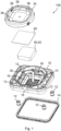
- Figure 1 depicts a venting unit 100 for venting a machinery space according to an embodiment of the invention in an exploded view.
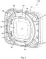
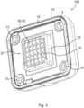
- Figure 2 depicts the venting unit 100 from a front side 36 in an isometric view, whereas in Figure 3 the venting unit 100 is shown from a rear side 37.
- Figure 4 the venting unit 100 is depicted in a sectional view.
- the machinery space may include, for example, a closed functional chamber of an electrical motor, in which wear parts (e.g., brushes) and/or oil mist are located and used.
- the machinery space may include a closed functional chamber including mechanical couplings (clutches) or brakes.
- the venting unit 100 comprises a support element 10 with a front side 36 and a rear side 37 related to an axial direction 42 ( Figure 4 ), with mounting elements 12 and a sealing element 14 for being mounted with the rear side 37 in a substantially fluid tight manner to an opening of the machinery space.
- the venting unit 100 has a fluid permeable passageway 16 for venting.
- the sealing element 14 is arranged on a circumference of the passageway 16 as is particularly to be seen in Figure 3 .
- the mounting elements 12 counteract during mounting of the venting unit 100 to the machinery space with the mounting domes 13 arranged in the corners of the support element 10.
- the venting unit 100 further comprises a semi-permeable membrane 40, covering the passageway 16.
- the semi-permeable membrane 40 is arranged at the support element 10 in a fluid tight manner and may connected by gluing, welding, clamping or the like.
- venting unit 100 comprises a filter element 50, being arranged at the support element 10 within the passageway 16 between the semi-permeable membrane 20 and the machinery space in an intended mounting state.
- the filter element 50 comprises a depth and/or surface filtration medium 52.
- the venting direction 30 is marked by an arrow being double-sided, as fluid like air may stream in both directions.
- the venting unit 100 is mainly intended for venting a machinery space from the rear side 37 of the venting unit 100 to the outside, yet as the venting unit 100 also is intended as a pressure compensation element air may also stream from the outside to the machinery space.
- Pressure compensation of the machinery space may be necessary because of temperature and/or location changes, resulting in different air pressures at different heights. Pressure differences to the environment may occur, which must be compensated sufficiently quickly to avoid an inadmissible load on an existing sealing system of the housing or the housing itself, as this can lead to water ingress and/or particle and/or oil droplet leakage respectively.
- the depth and/or surface filtration medium 52 may favorably comprise a nonwoven and/or a woven, as a flat filter element 50, in particular in a multiple folded configuration, and/or an open-celled foam-like medium, and/or a sponge-like medium, and/or a sintered thermoplastics or metal.
- a nonwoven and/or woven may comprise glass fibers with a diameter between 5 ⁇ m and 20 ⁇ m, preferably between 9 ⁇ m and 15 ⁇ m, preferably from mechanically bonded carded nonwovens made from textile glass staple fibers.
- a foam-like medium may have a porous structure between 20 ppi (pores per inch) and 150 ppi, preferably between 30 ppi and 120 ppi.
- a sponge-like medium may have a packing density between 10% and 22%, preferably between 3% and 15%, particularly preferred between 5% and 10%.
- a sintered thermoplastics may have a pore size between 1 ppi and 500 ppi, preferably between 2 ppi and 400 ppi, particularly preferred between 3 ⁇ m and 300 ⁇ m, and have a packing density between 4% and 90%, preferably between 6% and 80%.
- the sintered metal may have a pore size between 0.1 ⁇ m and 300 ⁇ m, preferably between 0.5 ⁇ m and 200 ⁇ m.
- a protection cover 34 is for the semi-permeable membrane 40 on the front side 36 of the support element 10.
- the protection cover 34 is fixed to the support element 10, e.g. by connection elements 44 ( Figure 4 ) such as a clamping system, and has several fluid through-flows 38 to the environment.
- the protection cover 34 protects the semi-permeable membrane 40 against influences from the outside.
- a fastening element for fixation of the filter element 50 to the support element 10 may be provided if convenient.
- sufficient support for the filter element 50 is integrated in the support element 10.
- the filter element 50 is mounted from the outside, after which the semi-permeable membrane 40 is also attached to the support element 10 from the outside in a sufficiently tight manner and, if required, the protective cover 34 may be also attached.
- the semi-permeable membrane 40 is thus in direct contact with the filter element 50, and may be mounted together with the filter element 50.
- the support element 10 has a recess 18.
- the recess 18 is part of the passageway 16, having a grille 19 towards the rear side 37, wherein the filter element 50 is arranged in the recess 18.
- the recess 18 with the grille 19 may particularly be seen in Figure 3 where the rear side 37 of the venting unit 100 is depicted.
- FIG 5 depicts a venting unit 100 for venting a machinery space according to a further embodiment of the invention in an exploded view.
- Figure 6 depicts the venting unit 100 from a front side 36 in an isometric view, whereas in Figure 7 the venting unit 100 is shown from a rear side 37.
- Figure 8 the venting unit 100 is depicted in a sectional view.
- Figure 9 a detail X of the venting unit 100 according to Fig. 8 is shown.
- a spacer element 22 as a covering area is integrated internally in the support element 10 for the semi-permeable membrane 40, which provides additional protection for the membrane against direct contact with existing particles and/or oil droplets and at the same time ensures a defined distance between the semi-permeable membrane 40 and the filter element 50.
- the filter element 50 is mounted from the rear side 37, independently of the membrane mounting, as seen from the intended installation condition. If necessary, the filter element 50 may be fixed in the support element 10 by the additional fastening element 24 which, also if necessary, provides sufficient support for the filter element 50.
- the structure for the support of the filter element 50 is gas-permeable and, in particular, may be formed as a grille 27.
- a gap 20 is provided between the semi-permeable membrane 40 and the filter element 50.
- the spacer element 22 may be arranged between the filter element 50 and the semi-permeable membrane 40 to provide the gap 20.
- the spacer element 22 may be configured as a grille 23, as shown in the Figures.
- a degree of coverage of an air-permeable area of the semi-permeable membrane 40 may be at least 5%, preferably at least 15%, most preferably at least 25%, of a maximum cross-section of the passageway 16.
- the covering area of the semi-permeable membrane 40 which to a certain extent also serves as a support for the semi-permeable membrane 40, may preferably be designed in such a way that the gas-permeable area is composed of a plurality of openings which, at least in their majority, follow simple geometric shapes such as circles, squares, rectangles or the like, wherein a degree of coverage of the air-permeable covering on the inlet side and/or outlet side is at least 5%, in particular at least 15%, in particular at least 25%, of a maximum cross-section of the air-permeable passageway, in particular, a cross-section of the recess 18.
- the venting unit 100 further includes a fastening element 24 configured to fixate the filter element 50 on the support element 10.
- the fastening element 24 has a grille 27 for fixating of the filter element 50 and for supporting the filter element 50, despite enabling a favorable venting of the machinery space.
- the fastening element 24 has an inflow protection 29 configured to protect the filter element 50 together, and has a fluid inlet 26 inclined to the axial direction 42 of the passageway 16.
- the fastening element 24 may be fixed on the recess 28 of the support element 10 by welding points or a welding line 25 ( Figure 8 ).
- the support element 10 may be designed on the inside, i.e. upstream side, of the fluid when the pressure is reduced from the inside of the machinery space to the outside, in such a way that the filter element is protected from a direct upstream flow.
- a further deflection of the fluid may take place, which not all particles and/or oil droplets can follow depending on the flow dynamics.
- This inflow protection 29 may also preferably be attached to the fastening element 24 for the filter element 50.
- the support element 10 has a recess 28.
- the recess 28 has an opening 32 to the rear side 37.
- the filter element 50 is arranged in the opening 32.
- the fastening element 24 is arranged at the opening 32 of the recess 28.
Landscapes
- Chemical & Material Sciences (AREA)
- Chemical Kinetics & Catalysis (AREA)
- Engineering & Computer Science (AREA)
- Analytical Chemistry (AREA)
- General Chemical & Material Sciences (AREA)
- Oil, Petroleum & Natural Gas (AREA)
- Filtering Of Dispersed Particles In Gases (AREA)
- Separation Using Semi-Permeable Membranes (AREA)
Abstract
Description
- The invention relates to a venting unit for venting a machinery space.
-
EP 2 007 500 B1 discloses a vent for an enclosure containing lubricated machinery. The vent comprises a body having a passageway there through and a gas permeable, water impermeable membrane covering the passageway. Further, the vent comprises a fibrous sorbent disposed within the passageway between the machinery space and the membrane. - It is an object of the invention to provide an improved venting unit for venting a machinery space.
- According to an aspect of the invention, the object is achieved by a venting unit for venting a machinery space, the venting unit including a support element with a front side and a rear side that are related to an axial direction, and mounting elements and a sealing element for being mounted with the rear side in a substantially fluid tight manner to an opening of the machinery space, the support element having a fluid permeable passageway for venting, and the sealing element being arranged surrounding the passageway. The venting unit further includes a semi-permeable membrane covering the passageway and being arranged at the support element in a fluid tight manner, a filter element being arranged at the support element, within the passageway, and between the semi-permeable membrane and the machinery space. The filter element includes a depth and/or surface filtration medium.
- Advantageous embodiments are described in the dependent claims, the description, and the drawings.
- Advantageously the proposed venting unit is adapted for venting machinery spaces in which fine particles and/or small oil droplets are created by a mechanically moving system and thus an aerosol can form. Such machinery spaces may comprise functional spaces of electro motors in which brushes are located, mechanical gears, mechanical clutches, mechanical brakes.
- The venting unit is intended to prevent very fine particles and/or oil droplets that are harmful to health from escaping from these rooms or chambers and thus polluting the environment directly or indirectly via other rooms or chambers. In the event that high-voltage components are located in one of the following rooms, a potential short circuit, for example in the form of a high-energy arc, can be effectively prevented. On the one hand, small, suspended, electrically conductive particles can significantly increase the electrical conductivity of the air, and on the other hand, small electrically conductive particles can, by being agglomerated on a surface and, lead to an undesirable leakage current or short circuit.
- By the proposed venting unit the penetration of water can be reliably prevented and thus the mechanical system can be protected, which is particularly desirable in the case of an electro-mechanical system, in order to protect it from a short circuit.
- Thus the venting unit may serve as a pressure compensation element, such as the semi-permeable membrane, that is suitably permeable to air but sufficiently watertight and also reliably prevents particles up to a certain degree of fineness from passing through it.
- Advantageously, the filter element may protect the semi-permeable membrane which usually reacts sensitively to contact with aerosols containing particles and/or oil droplets in such a way that the gas permeability and thus the pressure equalization capacity decreases the longer this exposure is present. The filter element consisting of a suitable filter medium favorably serves as a protection against particles and/or oil droplets. This filter element prevents increasing blocking of the semi-permeable membrane and extends its function significantly, if possible over its entire service life.
- An application example may be an electric motor which has a closed functional space in which the brushes are located. Due to the constant contact with the slip ring, abrasion in the form of very small particles occurs during rotation, which are capable of increasingly blocking the semi-permeable membrane. Due to an oil-lubricated bearing of the rotor or an adjacent oil-filled functional space for the rotor, fine oil droplets may also be present. By the filter element blocking of the semi-permeable membrane and thus the venting unit may be reduced to an absolute minimum.
- Advantageously the filter element may be integrated in the venting unit close to the semi-permeable membrane. The filter element may favorably be connected in series upstream of the semi-permeable membrane to be protected, according to the gas flowing out of the housing to reduce pressure.
- The semi-permeable membrane may be provided in the form of a microporous film, comprising in particular a fluoropolymer, in particular a polytetrafluoroethylene. The thickness of the semi-permeable membrane may be smaller by a multiple than a thickness of the depth and/or surface filtration medium of the filter element. In particular, the thickness of the semi-permeable membrane may be at least 10 times, in particular, at least 20 times, smaller than a thickness of the depth and/or surface filtration medium.
- According to a favorable embodiment of the venting unit, the depth and/or surface filtration medium may comprise a nonwoven and/or a woven, as a flat filter element, in particular in a multiple folded configuration, and/or an open-celled foam-like medium, and/or a sponge-like medium, and/or a sintered thermoplastics or metal. Thus advantageous filtering of the small particle and/or oil droplets out of the machinery space may be achieved.
- According to a favorable embodiment of the venting unit, the nonwoven and/or woven may comprise glass fibers with a diameter between 5 µm and 20 µm, preferably between 9 µm and 15 µm, preferably from mechanically bonded carded nonwovens made from textile glass staple fibers. Additionally or alternatively, the foam-like medium may have a porous structure between 20 ppi (pores per inch) and 150 ppi, preferably between 30 ppi and 120 ppi. Additionally or alternatively, the sponge-like medium may have a packing density between 10% and 22%, preferably between 3% and 15%, particularly preferred between 5% and 10%. Additionally or alternatively, the sintered thermoplastics may have a pore size between 1 ppi and 500 ppi, preferably between 2 ppi and 400 ppi, particularly preferred between 3 µm and 300 µm, and have a packing density between 4% and 90%, preferably between 6% and 80%. The sintered metal may have a pore size between 0.1 µm and 300 µm, preferably between 0.5 µm and 200 µm. Thus advantageous filtering of the small particle and/or oil droplets out of the machinery space may be achieved.
- According to a favorable embodiment of the venting unit, the support element may have a recess that is part of the passageway, and a grille towards the rear side. The filter element is arranged in the recess. By this way mounting of the filter element prior to mounting the semi-permeable membrane is possible.
- Since the filter element is mounted from the inside, independently of the semi-permeable membrane mounting, it can, if it is fixed by an additional fastening element. The filter element can be replaced by another consisting of a different medium, even if it has a different thickness. The fixation of the alternative filter element may be done by a corresponding change in the geometry of the fasting element or by a change in the end position of the fastening element through the assembly process. All other components and production steps may remain unaffected. This results in a venting unit which is advantageously very flexible in its filtration properties in order to meet the respective required specifications.
- According to a favorable embodiment of the venting unit, the filter element may be arranged in direct contact to the semi-permeable membrane. Thus, a reliable protection of the semi-permeable membrane from particles and/or oil droplets may be achieved.
- According to a favorable embodiment of the venting unit, a gap may be arranged between the semi-permeable membrane and the filter element. In particular, a spacer element may be arranged between the filter element and the semi-permeable membrane to provide the gap. In particular, the spacer element may be configured as a grille. By this way, the semi-permeable membrane may advantageously be stabilized against the ingress of water from the outside.
- According to a favorable embodiment of the venting unit, a degree of coverage of an air-permeable area of the semi-permeable membrane may be at least 5%, preferably at least 15%, most preferably at least 25%, of a maximum cross-section of the passageway. In many cases, the maximum cross-section will be a cross-section of the recess in which the filter element is placed. Thus, effective venting effect of the venting unit may be maintained or even improved, despite the stabilizing effect of the grille for the semi-permeable membrane, as the membrane may be particularly protected against the contact with particles and/or oil drops in the specific area directly behind the grille.
- According to a favorable embodiment of the venting unit, the venting unit further includes a fastening element configured to fixate the filter element on the support element. Easy mounting of the filter element in the manufacturing process may be achieved.
- According to a favorable embodiment of the venting unit, the fastening element may have a grille for fixating of the filter element. Reliable fixation of the filter element to the venting unit may be achieved.
- According to a favorable embodiment of the venting unit, the fastening element has an inflow protection configured to protect the filter element. Direct streaming of venting gases to the filter element may thus be prevented.
- According to a favorable embodiment of the venting unit, the fastening element has a fluid inlet inclined to the axial direction of the passageway. The filter element may thus be protected from abrasive effects by fast streaming venting gases.
- According to a favorable embodiment of the venting unit, the support element may have a recess, the recess having an opening to the rear side, wherein the filter element is arranged in the opening. Thus, in this embodiment, the filter element may advantageously be mounted from the rear side of the venting unit.
- According to a favorable embodiment of the venting unit, the fastening element may be arranged at the opening of the recess. By this way, the filter element may easily be mounted to the venting unit.
- According to a favorable embodiment of the venting unit, the venting unit further includes a protection cover for the semi-permeable membrane on the front side of the support element, the protection cover being fixed to the support element and having at least one fluid through-flow to the environment. Thus, the semi-permeable membrane may advantageously be protected from being damaged by something in the environment of the venting unit.
- The present invention together with the above-mentioned and other objects and advantages may best be understood from the following detailed description of the embodiments, but not restricted to the embodiments, wherein is shown in:
-
Figure 1 is a venting unit for venting a machinery space according to an embodiment of the invention in an exploded view; -
Figure 2 is the venting unit according toFig. 1 from a front side in an isometric view; -
Figure 3 is the venting unit according toFig. 1 from a rear side in an isometric view; -
Figure 4 is the venting unit according toFig. 1 in a sectional view; -
Figure 5 is a venting unit for venting a machinery space according to a further embodiment of the invention in an exploded view; -
Figure 6 is the venting unit according toFig. 5 from a front side in an isometric view; -
Figure 7 is the venting unit according toFig. 5 from a rear side in an isometric view; -
Figure 8 is the venting unit according toFig. 5 in a sectional view; and -
Figure 9 is a detail X of the venting unit according toFig. 8 . - In the drawings, like elements are referred to with equal reference numerals. The drawings are merely schematic representations, not intended to portray specific parameters of the invention. Moreover, the drawings are intended to depict only typical embodiments of the invention and therefore should not be considered as limiting the scope of the invention.
-
Figure 1 depicts aventing unit 100 for venting a machinery space according to an embodiment of the invention in an exploded view.Figure 2 depicts theventing unit 100 from afront side 36 in an isometric view, whereas inFigure 3 theventing unit 100 is shown from arear side 37. InFigure 4 theventing unit 100 is depicted in a sectional view. - The machinery space may include, for example, a closed functional chamber of an electrical motor, in which wear parts (e.g., brushes) and/or oil mist are located and used. Alternatively, the machinery space may include a closed functional chamber including mechanical couplings (clutches) or brakes.
- The
venting unit 100 comprises asupport element 10 with afront side 36 and arear side 37 related to an axial direction 42 (Figure 4 ), with mountingelements 12 and a sealingelement 14 for being mounted with therear side 37 in a substantially fluid tight manner to an opening of the machinery space. Theventing unit 100 has a fluidpermeable passageway 16 for venting. The sealingelement 14 is arranged on a circumference of thepassageway 16 as is particularly to be seen inFigure 3 . - The mounting
elements 12 counteract during mounting of theventing unit 100 to the machinery space with the mountingdomes 13 arranged in the corners of thesupport element 10. - The
venting unit 100 further comprises asemi-permeable membrane 40, covering thepassageway 16. Thesemi-permeable membrane 40 is arranged at thesupport element 10 in a fluid tight manner and may connected by gluing, welding, clamping or the like. - Further the
venting unit 100 comprises a filter element 50, being arranged at thesupport element 10 within thepassageway 16 between thesemi-permeable membrane 20 and the machinery space in an intended mounting state. The filter element 50 comprises a depth and/or surface filtration medium 52. - The venting
direction 30 is marked by an arrow being double-sided, as fluid like air may stream in both directions. Theventing unit 100 is mainly intended for venting a machinery space from therear side 37 of theventing unit 100 to the outside, yet as theventing unit 100 also is intended as a pressure compensation element air may also stream from the outside to the machinery space. - Pressure compensation of the machinery space may be necessary because of temperature and/or location changes, resulting in different air pressures at different heights. Pressure differences to the environment may occur, which must be compensated sufficiently quickly to avoid an inadmissible load on an existing sealing system of the housing or the housing itself, as this can lead to water ingress and/or particle and/or oil droplet leakage respectively.
- The depth and/or surface filtration medium 52 may favorably comprise a nonwoven and/or a woven, as a flat filter element 50, in particular in a multiple folded configuration, and/or an open-celled foam-like medium, and/or a sponge-like medium, and/or a sintered thermoplastics or metal.
- A nonwoven and/or woven may comprise glass fibers with a diameter between 5 µm and 20 µm, preferably between 9 µm and 15 µm, preferably from mechanically bonded carded nonwovens made from textile glass staple fibers.
- A foam-like medium may have a porous structure between 20 ppi (pores per inch) and 150 ppi, preferably between 30 ppi and 120 ppi.
- A sponge-like medium may have a packing density between 10% and 22%, preferably between 3% and 15%, particularly preferred between 5% and 10%.
- A sintered thermoplastics may have a pore size between 1 ppi and 500 ppi, preferably between 2 ppi and 400 ppi, particularly preferred between 3 µm and 300 µm, and have a packing density between 4% and 90%, preferably between 6% and 80%. The sintered metal may have a pore size between 0.1 µm and 300 µm, preferably between 0.5 µm and 200 µm.
- A
protection cover 34 is for thesemi-permeable membrane 40 on thefront side 36 of thesupport element 10. Theprotection cover 34 is fixed to thesupport element 10, e.g. by connection elements 44 (Figure 4 ) such as a clamping system, and has several fluid through-flows 38 to the environment. Theprotection cover 34 protects thesemi-permeable membrane 40 against influences from the outside. - A fastening element for fixation of the filter element 50 to the
support element 10 may be provided if convenient. - In the embodiment depicted in
Figures 1 to 4 , sufficient support for the filter element 50 is integrated in thesupport element 10. The filter element 50 is mounted from the outside, after which thesemi-permeable membrane 40 is also attached to thesupport element 10 from the outside in a sufficiently tight manner and, if required, theprotective cover 34 may be also attached. Thesemi-permeable membrane 40 is thus in direct contact with the filter element 50, and may be mounted together with the filter element 50. - For accommodating the filter element 50, the
support element 10 has arecess 18. Therecess 18 is part of thepassageway 16, having agrille 19 towards therear side 37, wherein the filter element 50 is arranged in therecess 18. Therecess 18 with thegrille 19 may particularly be seen inFigure 3 where therear side 37 of theventing unit 100 is depicted. -
Figure 5 depicts aventing unit 100 for venting a machinery space according to a further embodiment of the invention in an exploded view.Figure 6 depicts theventing unit 100 from afront side 36 in an isometric view, whereas inFigure 7 theventing unit 100 is shown from arear side 37. InFigure 8 theventing unit 100 is depicted in a sectional view. InFigure 9 a detail X of theventing unit 100 according toFig. 8 is shown. - In this second embodiment, a spacer element 22 as a covering area is integrated internally in the
support element 10 for thesemi-permeable membrane 40, which provides additional protection for the membrane against direct contact with existing particles and/or oil droplets and at the same time ensures a defined distance between thesemi-permeable membrane 40 and the filter element 50. Whereas in this embodiment, in contrast to the previously described first embodiment, the filter element 50 is mounted from therear side 37, independently of the membrane mounting, as seen from the intended installation condition. If necessary, the filter element 50 may be fixed in thesupport element 10 by theadditional fastening element 24 which, also if necessary, provides sufficient support for the filter element 50. The structure for the support of the filter element 50 is gas-permeable and, in particular, may be formed as agrille 27. - A
gap 20 is provided between thesemi-permeable membrane 40 and the filter element 50. In particular, as depicted in the Figures, the spacer element 22 may be arranged between the filter element 50 and thesemi-permeable membrane 40 to provide thegap 20. In particular, the spacer element 22 may be configured as a grille 23, as shown in the Figures. - Advantageously, a degree of coverage of an air-permeable area of the
semi-permeable membrane 40 may be at least 5%, preferably at least 15%, most preferably at least 25%, of a maximum cross-section of thepassageway 16. Thus, there may be enough free space for fluid streaming from the machinery space through thepassageway 16 to the outside. - The covering area of the
semi-permeable membrane 40, which to a certain extent also serves as a support for thesemi-permeable membrane 40, may preferably be designed in such a way that the gas-permeable area is composed of a plurality of openings which, at least in their majority, follow simple geometric shapes such as circles, squares, rectangles or the like, wherein a degree of coverage of the air-permeable covering on the inlet side and/or outlet side is at least 5%, in particular at least 15%, in particular at least 25%, of a maximum cross-section of the air-permeable passageway, in particular, a cross-section of therecess 18. - In
Figure 9 the detail X exemplifies the coverage of thesemi-permeable membrane 40 by thewebs 21 of the grille 23. - The
venting unit 100 further includes afastening element 24 configured to fixate the filter element 50 on thesupport element 10. Thefastening element 24 has agrille 27 for fixating of the filter element 50 and for supporting the filter element 50, despite enabling a favorable venting of the machinery space. - Further, as shown with the embodiment, the
fastening element 24 has aninflow protection 29 configured to protect the filter element 50 together, and has afluid inlet 26 inclined to theaxial direction 42 of thepassageway 16. In particular in the case of aninflow protection 29, thefastening element 24 may be fixed on therecess 28 of thesupport element 10 by welding points or a welding line 25 (Figure 8 ). - The
support element 10 may be designed on the inside, i.e. upstream side, of the fluid when the pressure is reduced from the inside of the machinery space to the outside, in such a way that the filter element is protected from a direct upstream flow. Advantageously, a further deflection of the fluid may take place, which not all particles and/or oil droplets can follow depending on the flow dynamics. Thisinflow protection 29 may also preferably be attached to thefastening element 24 for the filter element 50. - For accommodating the filter element 50, the
support element 10 has arecess 28. Therecess 28 has anopening 32 to therear side 37. The filter element 50 is arranged in theopening 32. Further, thefastening element 24 is arranged at theopening 32 of therecess 28. -
- 10
- support element
- 12
- mounting element
- 13
- mounting dome
- 14
- sealing element
- 16
- passageway
- 18
- recess
- 19
- grille
- 20
- gap
- 21
- web
- 22
- spacer element
- 23
- grille
- 24
- fastening element
- 25
- welding points or line
- 26
- fluid inlet
- 27
- grille
- 28
- recess
- 29
- inflow protection
- 30
- venting direction
- 32
- opening
- 34
- protection cover
- 36
- front side
- 37
- rear side
- 38
- fluid through-flow
- 40
- semi-permeable membrane
- 42
- axial direction
- 44
- connecting element
- 50
- filter element
- 52
- depth and/or surface filtration medium
- 100
- venting unit
Claims (15)
- A venting unit (100) for venting a machinery space, the venting unit (100) comprisinga support element (10) with a front side (36) and a rear side (37) that are related to an axial direction (42);one or more mounting elements (12) and a sealing element (14) for being mounted with the rear side (37) in a substantially fluid tight manner to an opening of the machinery space, the support element (10) having a fluid permeable passageway (16) for venting, and the sealing element (14) being arranged surrounding the passageway (16);a semi-permeable membrane (40) covering the passageway (16) and being arranged at the support element (10) in a fluid tight manner;a filter element (50) being arranged at the support element (10), within the passageway (16), and between the semi-permeable membrane (20) and the machinery space,wherein the filter element (50) comprises a depth and/or surface filtration medium (52).
- The venting unit according to claim 1, wherein the depth and/or surface filtration medium (52) comprises a nonwoven and/or a woven, as a flat filter element (50), in particular in a multiple folded configuration.
- The venting unit according to claim 2, wherein the nonwoven and/or the woven comprises glass fibers with a diameter between 5 µm and 20 µm, preferably between 9 µm and 15 µm, preferably from mechanically bonded carded nonwovens made from textile glass staple fibers.
- The venting unit according to claim 1, wherein the depth and/or surface filtration medium (52) comprises an open-celled foam-like medium, and/or a sponge-like medium, and/or a sintered thermoplastics or metal.
- The venting unit according to claim 4, wherein the foam-like medium has a porous structure between 20 ppi and 150 ppi, preferably between 30 ppi and 120 ppi, and/orwherein the sponge-like medium has a packing density between 10% and 22%, preferably between 3% and 15%, particularly preferred between 5% and 10%, and/orwherein the sintered thermoplastics has a pore size between 1 ppi and 500 ppi, preferably between 2 ppi and 400 ppi, particularly preferred between 3 µm and 300 µm, and has a packing density between 4% and 90%, preferably between 6% and 80%, and/orwherein the sintered metal has a pore size between 0.1 µm and 300 µm, preferably between 0.5 µm and 200 µm.
- The venting unit according to any one of the preceding claims, wherein the support element (10) has a recess (18) that is part of the passageway (16), and a grille (19) towards the rear side (37), and
wherein the filter element (50) is arranged in the recess (18). - The venting unit according to any one of the preceding claims, wherein the filter element (50) is arranged in direct contact to the semi-permeable membrane (40).
- The venting unit according to any one of the claims 1 to 6, wherein a gap (20) is arranged between the semi-permeable membrane (40) and the filter element (50), in particular, wherein a spacer element (22) is arranged between the filter element (50) and the semi-permeable membrane (40) to provide the gap (20), in particular, wherein the spacer element (22) is configured as a grille (23).
- The venting unit according to claim 8, wherein a degree of coverage of an air-permeable area of the semi-permeable membrane (40) is at least 5%, preferably at least 15%, most preferably at least 25%, of a maximum cross-section of the passageway (16), in particular, a cross-section of the recess (18).
- The venting unit according to any one of the claims 1 to 5, further comprising a fastening element (24) configured to fixate the filter element (50) on the support element (10).
- The venting unit according to claim 10, wherein the fastening element (24) has a grille (27) for fixating of the filter element (50).
- The venting unit according to claim 10 or 11, wherein the fastening element (24) has an inflow protection (29) configured to protect the filter element (50).
- The venting unit according to any one of the claims 10 to 12, wherein the fastening element (24) has a fluid inlet (26) inclined to the axial direction (42) of the passageway (16).
- The venting unit according to any one of the claims 10 to 13, wherein the support element (10) has a recess (28), the recess (28) having an opening (32) to the rear side (37), and
wherein the filter element (50) is arranged in the opening (32). - The venting unit according to claim 14, wherein the fastening element (24) is arranged at the opening (32) of the recess (28).
Priority Applications (3)
| Application Number | Priority Date | Filing Date | Title |
|---|---|---|---|
| EP23158911.0A EP4424403A1 (en) | 2023-02-28 | 2023-02-28 | Venting unit for venting a machinery space |
| US18/430,633 US20240286085A1 (en) | 2023-02-28 | 2024-02-01 | Venting unit for venting machinery space |
| CN202410221244.6A CN118558115A (en) | 2023-02-28 | 2024-02-28 | Ventilation unit for ventilating machine spaces |
Applications Claiming Priority (1)
| Application Number | Priority Date | Filing Date | Title |
|---|---|---|---|
| EP23158911.0A EP4424403A1 (en) | 2023-02-28 | 2023-02-28 | Venting unit for venting a machinery space |
Publications (1)
| Publication Number | Publication Date |
|---|---|
| EP4424403A1 true EP4424403A1 (en) | 2024-09-04 |
Family
ID=85570227
Family Applications (1)
| Application Number | Title | Priority Date | Filing Date |
|---|---|---|---|
| EP23158911.0A Pending EP4424403A1 (en) | 2023-02-28 | 2023-02-28 | Venting unit for venting a machinery space |
Country Status (3)
| Country | Link |
|---|---|
| US (1) | US20240286085A1 (en) |
| EP (1) | EP4424403A1 (en) |
| CN (1) | CN118558115A (en) |
Families Citing this family (1)
| Publication number | Priority date | Publication date | Assignee | Title |
|---|---|---|---|---|
| EP4325645A1 (en) * | 2022-08-19 | 2024-02-21 | MANN+HUMMEL GmbH | Degassing unit with segmented membrane |
Citations (5)
| Publication number | Priority date | Publication date | Assignee | Title |
|---|---|---|---|---|
| EP2007500B1 (en) | 2006-04-17 | 2010-12-01 | Gore Enterprise Holdings, Inc. | Axle vent |
| DE102012022346A1 (en) * | 2012-11-15 | 2014-05-15 | Mann+Hummel Gmbh | Battery case for lithium ion battery or accumulator in e.g. hybrid vehicle, has support body, diaphragm and housing water-tightly connected with each other, and multiple grid openings arranged between diaphragm support grid webs |
| EP3916899A1 (en) * | 2020-05-26 | 2021-12-01 | MANN+HUMMEL GmbH | Degassing unit and electronics enclosure, in particular battery housing |
| US20220223974A1 (en) * | 2021-01-14 | 2022-07-14 | Mann+Hummel Gmbh | Battery Degassing Unit and Battery Housing |
| US20220344772A1 (en) * | 2021-04-26 | 2022-10-27 | Mann+Hummel Gmbh | Venting Unit and Housing, in Particular Battery Housing |
Family Cites Families (6)
| Publication number | Priority date | Publication date | Assignee | Title |
|---|---|---|---|---|
| US5108853A (en) * | 1990-12-20 | 1992-04-28 | Exide Corporation | Submersible and flame retardant battery vent plug |
| US5209992A (en) * | 1990-12-20 | 1993-05-11 | Exide Corporation | Water by-passing, flame retardant battery vent plug |
| US5217823A (en) * | 1991-12-10 | 1993-06-08 | Globe-Union Inc. | Explosion resistant vent cap |
| US5458988A (en) * | 1993-08-10 | 1995-10-17 | Matsi, Inc. | Metal-air-cells having improved anode assemblies |
| US6613473B1 (en) * | 2000-09-11 | 2003-09-02 | Leon Tong | Battery with cylindrical cells |
| DE102005019296A1 (en) * | 2005-04-26 | 2006-11-09 | Deutsche Exide Gmbh | Degassing valve for acid batteries |
-
2023
- 2023-02-28 EP EP23158911.0A patent/EP4424403A1/en active Pending
-
2024
- 2024-02-01 US US18/430,633 patent/US20240286085A1/en active Pending
- 2024-02-28 CN CN202410221244.6A patent/CN118558115A/en active Pending
Patent Citations (5)
| Publication number | Priority date | Publication date | Assignee | Title |
|---|---|---|---|---|
| EP2007500B1 (en) | 2006-04-17 | 2010-12-01 | Gore Enterprise Holdings, Inc. | Axle vent |
| DE102012022346A1 (en) * | 2012-11-15 | 2014-05-15 | Mann+Hummel Gmbh | Battery case for lithium ion battery or accumulator in e.g. hybrid vehicle, has support body, diaphragm and housing water-tightly connected with each other, and multiple grid openings arranged between diaphragm support grid webs |
| EP3916899A1 (en) * | 2020-05-26 | 2021-12-01 | MANN+HUMMEL GmbH | Degassing unit and electronics enclosure, in particular battery housing |
| US20220223974A1 (en) * | 2021-01-14 | 2022-07-14 | Mann+Hummel Gmbh | Battery Degassing Unit and Battery Housing |
| US20220344772A1 (en) * | 2021-04-26 | 2022-10-27 | Mann+Hummel Gmbh | Venting Unit and Housing, in Particular Battery Housing |
Also Published As
| Publication number | Publication date |
|---|---|
| US20240286085A1 (en) | 2024-08-29 |
| CN118558115A (en) | 2024-08-30 |
Similar Documents
| Publication | Publication Date | Title |
|---|---|---|
| KR102115756B1 (en) | Pressure compensation device for a housing | |
| JP7474893B2 (en) | Vent with relief valve | |
| US5785390A (en) | Vented hubcap | |
| US20240286085A1 (en) | Venting unit for venting machinery space | |
| CN101466452B (en) | Axle case ventilation pipe | |
| CN101156008B (en) | Shaft sealing and vacuum pump with the shaft sealing | |
| CN115768991A (en) | Rolling bearing device | |
| CN118089810A (en) | Housing and heating, ventilation and air conditioning system comprising the same | |
| US20220112962A1 (en) | Enclosure vent assembly | |
| US12089352B2 (en) | Pressure equalising device and housing comprising the pressure equalising device | |
| US20250283548A1 (en) | Pressure equalization apparatus and use thereof | |
| CN117989322A (en) | Safety seal for sealing a duct in a motor vehicle | |
| CN210114921U (en) | Filter cartridge and filter | |
| WO2004016974A1 (en) | Pressure relief valve | |
| US20260074366A1 (en) | Filter device and battery housing with filter device | |
| CN221237237U (en) | Novel waterproof oil-filtering ventilation valve for new energy automobile driving unit | |
| WO2026076121A1 (en) | Breather assembly with flow channels | |
| CN113137504A (en) | Explosion valve | |
| GB2547256A (en) | Waterproof respirator filter | |
| WO2018069796A1 (en) | A filter cartridge for a compressor or vacuum pump |
Legal Events
| Date | Code | Title | Description |
|---|---|---|---|
| PUAI | Public reference made under article 153(3) epc to a published international application that has entered the european phase |
Free format text: ORIGINAL CODE: 0009012 |
|
| STAA | Information on the status of an ep patent application or granted ep patent |
Free format text: STATUS: THE APPLICATION HAS BEEN PUBLISHED |
|
| AK | Designated contracting states |
Kind code of ref document: A1 Designated state(s): AL AT BE BG CH CY CZ DE DK EE ES FI FR GB GR HR HU IE IS IT LI LT LU LV MC ME MK MT NL NO PL PT RO RS SE SI SK SM TR |
|
| STAA | Information on the status of an ep patent application or granted ep patent |
Free format text: STATUS: REQUEST FOR EXAMINATION WAS MADE |
|
| 17P | Request for examination filed |
Effective date: 20250220 |
|
| STAA | Information on the status of an ep patent application or granted ep patent |
Free format text: STATUS: EXAMINATION IS IN PROGRESS |
|
| 17Q | First examination report despatched |
Effective date: 20250509 |