EP2007500B1 - Axle vent - Google Patents
Axle vent Download PDFInfo
- Publication number
- EP2007500B1 EP2007500B1 EP07754813A EP07754813A EP2007500B1 EP 2007500 B1 EP2007500 B1 EP 2007500B1 EP 07754813 A EP07754813 A EP 07754813A EP 07754813 A EP07754813 A EP 07754813A EP 2007500 B1 EP2007500 B1 EP 2007500B1
- Authority
- EP
- European Patent Office
- Prior art keywords
- membrane
- vent
- fibers
- passageway
- sorbent
- Prior art date
- Legal status (The legal status is an assumption and is not a legal conclusion. Google has not performed a legal analysis and makes no representation as to the accuracy of the status listed.)
- Active
Links
Images


Classifications
-
- F—MECHANICAL ENGINEERING; LIGHTING; HEATING; WEAPONS; BLASTING
- F16—ENGINEERING ELEMENTS AND UNITS; GENERAL MEASURES FOR PRODUCING AND MAINTAINING EFFECTIVE FUNCTIONING OF MACHINES OR INSTALLATIONS; THERMAL INSULATION IN GENERAL
- F16H—GEARING
- F16H57/00—General details of gearing
- F16H57/02—Gearboxes; Mounting gearing therein
- F16H57/027—Gearboxes; Mounting gearing therein characterised by means for venting gearboxes, e.g. air breathers
-
- B—PERFORMING OPERATIONS; TRANSPORTING
- B01—PHYSICAL OR CHEMICAL PROCESSES OR APPARATUS IN GENERAL
- B01D—SEPARATION
- B01D50/00—Combinations of methods or devices for separating particles from gases or vapours
-
- B—PERFORMING OPERATIONS; TRANSPORTING
- B01—PHYSICAL OR CHEMICAL PROCESSES OR APPARATUS IN GENERAL
- B01D—SEPARATION
- B01D46/00—Filters or filtering processes specially modified for separating dispersed particles from gases or vapours
- B01D46/0027—Filters or filtering processes specially modified for separating dispersed particles from gases or vapours with additional separating or treating functions
- B01D46/0036—Filters or filtering processes specially modified for separating dispersed particles from gases or vapours with additional separating or treating functions by adsorption or absorption
-
- B—PERFORMING OPERATIONS; TRANSPORTING
- B01—PHYSICAL OR CHEMICAL PROCESSES OR APPARATUS IN GENERAL
- B01D—SEPARATION
- B01D46/00—Filters or filtering processes specially modified for separating dispersed particles from gases or vapours
- B01D46/56—Filters or filtering processes specially modified for separating dispersed particles from gases or vapours with multiple filtering elements, characterised by their mutual disposition
- B01D46/62—Filters or filtering processes specially modified for separating dispersed particles from gases or vapours with multiple filtering elements, characterised by their mutual disposition connected in series
- B01D46/64—Filters or filtering processes specially modified for separating dispersed particles from gases or vapours with multiple filtering elements, characterised by their mutual disposition connected in series arranged concentrically or coaxially
-
- B—PERFORMING OPERATIONS; TRANSPORTING
- B01—PHYSICAL OR CHEMICAL PROCESSES OR APPARATUS IN GENERAL
- B01D—SEPARATION
- B01D53/00—Separation of gases or vapours; Recovering vapours of volatile solvents from gases; Chemical or biological purification of waste gases, e.g. engine exhaust gases, smoke, fumes, flue gases, aerosols
- B01D53/14—Separation of gases or vapours; Recovering vapours of volatile solvents from gases; Chemical or biological purification of waste gases, e.g. engine exhaust gases, smoke, fumes, flue gases, aerosols by absorption
-
- F—MECHANICAL ENGINEERING; LIGHTING; HEATING; WEAPONS; BLASTING
- F01—MACHINES OR ENGINES IN GENERAL; ENGINE PLANTS IN GENERAL; STEAM ENGINES
- F01M—LUBRICATING OF MACHINES OR ENGINES IN GENERAL; LUBRICATING INTERNAL COMBUSTION ENGINES; CRANKCASE VENTILATING
- F01M1/00—Pressure lubrication
- F01M1/10—Lubricating systems characterised by the provision therein of lubricant venting or purifying means, e.g. of filters
-
- F—MECHANICAL ENGINEERING; LIGHTING; HEATING; WEAPONS; BLASTING
- F16—ENGINEERING ELEMENTS AND UNITS; GENERAL MEASURES FOR PRODUCING AND MAINTAINING EFFECTIVE FUNCTIONING OF MACHINES OR INSTALLATIONS; THERMAL INSULATION IN GENERAL
- F16K—VALVES; TAPS; COCKS; ACTUATING-FLOATS; DEVICES FOR VENTING OR AERATING
- F16K17/00—Safety valves; Equalising valves, e.g. pressure relief valves
- F16K17/20—Excess-flow valves
- F16K17/22—Excess-flow valves actuated by the difference of pressure between two places in the flow line
- F16K17/24—Excess-flow valves actuated by the difference of pressure between two places in the flow line acting directly on the cutting-off member
- F16K17/26—Excess-flow valves actuated by the difference of pressure between two places in the flow line acting directly on the cutting-off member operating in either direction
-
- F—MECHANICAL ENGINEERING; LIGHTING; HEATING; WEAPONS; BLASTING
- F16—ENGINEERING ELEMENTS AND UNITS; GENERAL MEASURES FOR PRODUCING AND MAINTAINING EFFECTIVE FUNCTIONING OF MACHINES OR INSTALLATIONS; THERMAL INSULATION IN GENERAL
- F16K—VALVES; TAPS; COCKS; ACTUATING-FLOATS; DEVICES FOR VENTING OR AERATING
- F16K24/00—Devices, e.g. valves, for venting or aerating enclosures
- F16K24/04—Devices, e.g. valves, for venting or aerating enclosures for venting only
-
- Y—GENERAL TAGGING OF NEW TECHNOLOGICAL DEVELOPMENTS; GENERAL TAGGING OF CROSS-SECTIONAL TECHNOLOGIES SPANNING OVER SEVERAL SECTIONS OF THE IPC; TECHNICAL SUBJECTS COVERED BY FORMER USPC CROSS-REFERENCE ART COLLECTIONS [XRACs] AND DIGESTS
- Y10—TECHNICAL SUBJECTS COVERED BY FORMER USPC
- Y10T—TECHNICAL SUBJECTS COVERED BY FORMER US CLASSIFICATION
- Y10T74/00—Machine element or mechanism
- Y10T74/21—Elements
- Y10T74/2186—Gear casings
- Y10T74/2188—Axle and torque tubes
Definitions
- baffles, coalescing media or valve assemblies which permit expanding air to escape through valve openings. During cooling periods, such assemblies permit air ingress through a second valve assembly, or through a membrane. Such assemblies necessarily incorporate numerous moving parts which are subject to wear and have increased assembly complexity.
- the invention provides a vent having the features of claim 1.
- Gear Case is meant as an axle, transmission, transfer case and other assembly having lubricated moving parts generating shear forces on the lubricant.
- the body may be formed from, or consist entirely of, the vent membrane or a laminate comprising the vent membrane.
- the membrane of laminate may be formed by thermal or mechanical means to create a pouch for the sorbent.
- the flange of the membrane is sealed to encapsulate the sorbent and provide a liquid tight seal.
- fibrous sorbent (2) is disposed between two layers of membrane (3).
- the one membrane includes a hole, which provides a passageway (16).
- the vent may include adhesive media (31) to attach the vent to a machinery housing.
- the invention provides a venting system having a sorbent that maintains adequate inter-fiber void space. Sorption of oil helps to maintain inter-fiber void space in the sorbent.
- the fibrous sorbent is comprised of fibers having features which promote sorption of lubricant aerosols.
- Sorbent fibers may be adapted to promote adsorption, absorption, and, preferably both.
- the fibers may be absorbent.
- Absorbent fibers include internal physical or chemical structure that promotes migration of lubricant below the surface of the fiber, thereby preserving inter-fiber void space and maintaining pressure drop across the sorbent. Physical features promoting absorption include hollow lumen structures and chemical compositions that promote oil absorption.
- the fibrous sorbent contains fibers that are hollow or contain significant void spaces.
- the fibers of the sorbent are hydrophobic.
- the fibers of the sorbent may also include synthetic fibers.
- Synthetic fibers such as polyester, polypropylene, nylon and acetate which have an engineered surface profile, are effective.
- Super adsorbent fibers with hydrophobic coatings may also have application as sorbents.
- hollow synthetic fibers may be useful in certain applications. Where synthetic fibers are used, hydrophobic fibers are particularly preferred.
Landscapes
- Engineering & Computer Science (AREA)
- General Engineering & Computer Science (AREA)
- Mechanical Engineering (AREA)
- Chemical & Material Sciences (AREA)
- Chemical Kinetics & Catalysis (AREA)
- Analytical Chemistry (AREA)
- General Chemical & Material Sciences (AREA)
- Oil, Petroleum & Natural Gas (AREA)
- Separation Using Semi-Permeable Membranes (AREA)
- Solid-Sorbent Or Filter-Aiding Compositions (AREA)
- General Details Of Gearings (AREA)
- Tents Or Canopies (AREA)
- Filtering Materials (AREA)
- Transplanting Machines (AREA)
- Self-Closing Valves And Venting Or Aerating Valves (AREA)
- Devices For Conveying Motion By Means Of Endless Flexible Members (AREA)
- Laminated Bodies (AREA)
Abstract
Description
- The invention relates to the field of machinery venting. More specifically, the invention provides a novel vent for an enclosure containing lubricated machinery, according to the preamble of claim 1.
- Gas-permeable, liquid-impermeable vents find use in many applications in the automotive industry, such as electrical component housings, gear housings, vehicle bodies, brake housings, etc. where pressure equalization between the housing interior and surrounding environment must occur. While vents must allow for gas pressure equalization, they must also seal the interior of the housing from liquid, dirt and dust particles. Failure to exclude liquids such as water can damage the components and corrode the housing.
- Machinery enclosures such as gearbox housings, axles and the like are subject to thermal cycling. As the machinery is operated, temperatures of the lubricant and internal air begin to rise, causing air pressure to rise in the enclosure. When the machinery is stopped, pressure falls within the enclosure. To accommodate changes in air pressure from operating temperature changes, vents are required. If effective venting is not provided, seals and gaskets may be compromised. It is important that contaminants be prevented from entering the machinery enclosure. Contaminants and water will severely degrade the effectiveness of lubricant, which results in premature wear of the machinery.
- Machinery vents have incorporated expanded Polytetrafluoroethylene (ePTFE) membranes. Such membranes are known for water impermeabily and air permeability and therefore not only prevent contaminants from entering the gear case, but also contain the lubricant to prevent spillage. However, ePTFE vents are subject to rapid blinding as lubricant aerosol particles fill the membrane pores and block airflow. Accordingly, known ePTFE vents had limited service life.
- Other attempts at venting machinery spaces have incorporated baffles, coalescing media or valve assemblies which permit expanding air to escape through valve openings. During cooling periods, such assemblies permit air ingress through a second valve assembly, or through a membrane. Such assemblies necessarily incorporate numerous moving parts which are subject to wear and have increased assembly complexity.
- Some machinery vents are mounted remotely from the machinery. Remote mounting allows the vent to be placed in an area with limited environmental exposure, and could reduce the problems associated with lubricant blinding. Other gear cases incorporate a simple snorkel to vent the case to a remote and relatively protected area. Such snorkels provide little protection from contamination and will not prevent lubricant spillage. Moreover, all remote mounting approaches introduce additional parts cost and installation complexity.
- What is needed is a vent without moving parts that can be mounted in close proximity or directly to a machinery enclosure that allows adequate air passage, prevents contaminants and liquid from entering the machinery space, and retains liquids inside the enclosure in the event it is oriented to allow liquids to contact the vent.
- The closest prior art
WO 2005/100832 discloses a vent with a metal body and a porous membrane, wherein an interference relation between the membrane and the body forms a seal. - In one embodiment, the invention provides a vent having the features of claim 1.
- Further embodiments of the invention are outlined in the dependent claims 2-13.
-
-
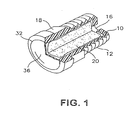
Figure 1 depicts a perspective view of one aspect of the inventive vent -
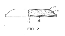
Figure 2 depicts another embodiment of a vent according to the present invention. -
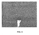
Figure 3 is a photograph showing the microstructure of cotton fiber. -
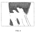
Figure 4 is a photograph of a synthetic fiber with engineered surface features. -
Figure 5 is a chart depicting the airflow for various sorbent media. -
Figure 6 depicts a schematic diagram of the apparatus use to test venting performance. - By "Absorption" is meant a process by which liquid or gas molecules are taken up, or enter a bulk phase, this differs from adsorption because the particles are taken up by a volume rather than by a surface. An absorbent retains liquid or gas molecules by absorption.
- By "Adsorption" is meant a process by which a liquid or gas molecules accumulate on the surface of a solid. An "adsorbent" retains liquid or gas molecules by adsorption.
- By "Aerosol" is meant a gaseous suspension of fine (0.10 - 100 µm) solid or liquid particles. An aerosol includes a mist, cloud, fog and the like.
- By "Oleophilic" is meant a material that has a surface with an affinity for oil.
- By "Gear Case" is meant as an axle, transmission, transfer case and other assembly having lubricated moving parts generating shear forces on the lubricant.
- By "Hydrophobic" is meant materials that have a surface that is extremely difficult to wet with water, with water contact angles in excess of 90°.
- By "Sorbent" is meant a solid material having the ability to retain gasses or liquids; as used herein, Sorbent includes materials that are absorbent, adsorbent or both.
- The vent body of the present invention may be machined or cast from metallic or polymeric materials. When used as an axle or automotive machinery vent, the vent may be installed in a cast iron housing. Accordingly, if metal vents are preferred, they may be machined from stainless steel to avoid corrosion and bi metallic corrosion. Alternatively, metal vents may be plated with zinc for example to inhibit corrosion. Preferably, the bodies of the inventive vents are constructed from polymeric materials. Polymeric vent bodies facilitate easy processing, including heat sealing of the membrane to the body. Polymeric materials are low cost and are not subject to corrosion. Most preferably, the polymeric material is a polyamide. Polyamide 6.6 is ultimately preferred because of its favorable cost and strength.
- The vent body may be constructed in various shapes conducive to easy installation in machinery housings. Those of skill in the art will comprehend press in type vents, which seal by interference fit, threaded vents, barbs, adhesives and other attachment means may be utilized with due regard to the intended application. The form of the vent body is not critical, provided that a through passageway extends through the body to allow the passage of air.
- In some applications, an elastomer is the preferred body material. The compliance and resilience of such materials allow them to compensate for tolerances in mating components such as these in the machinery enclosure. In addition, in applications where impact from foreign objects is possible, such materials can be less prone to damage or failure.
- The passageway may be machined or cast within the vent body. While many methods of providing the passageway are apparent, the vent body is preferably cast or molded with a passageway there through to avoid the additional processing of boring the body. The passageway defines a volume sufficient to contain sorbent media. This volume may be defined by a straight or tapered bore. Preferably, a counter bore may be provided proximate to the head of the vent. The counter bore is sufficiently voluminous to contain sorbent material, while the narrower bore proximate to the machinery enclosure serves to contain the sorbent material and provide the passageway from the machinery enclosure to the sorbent.
- With reference to
Figure 1 , a vent body (10) is provided having a passageway (16) there through. The body incorporates a threaded portion (12) for insertion in a tapped hole in a machinery enclosure. The body further includes a hexagonal portion (18) for driving the vent into the tapped hole. Fibrous sorbent (20) is disposed within the passageway. The open end of the passageway is covered by a membrane (30) to prevent water from entering the enclosure. The membrane is attached to the vent body by a heat seal (32). - It is desirable to prevent liquids lubricants within the machinery enclosure from contacting the sorbent media. Accordingly, check, ball or other one-way flow control devices (not shown) may be incorporated into the passageway (16) of the vent body. Alternatively, the passageway may incorporate a tortuous path therein to contain the lubricant and prevent it from contacting the sorbent and or membrane.
- The fibrous sorbent (20) effectively prevents membrane (30) from blinding by reducing the amount of lubricant aerosol that contacts the membrane, while maintaining adequate airflow for venting.
- In another aspect, the body may be formed from, or consist entirely of, the vent membrane or a laminate comprising the vent membrane. In this embodiment, the membrane of laminate may be formed by thermal or mechanical means to create a pouch for the sorbent. In this embodiment, the flange of the membrane is sealed to encapsulate the sorbent and provide a liquid tight seal.
- With reference to
Figure 2 , fibrous sorbent (2) is disposed between two layers of membrane (3). The one membrane includes a hole, which provides a passageway (16). The vent may include adhesive media (31) to attach the vent to a machinery housing. - During venting, air passes through inter-fiber void spaces of the sorbent. Inter-fiber voids are necessary to maintain low pressure drop through the sorbent. In one aspect, the invention provides a venting system having a sorbent that maintains adequate inter-fiber void space. Sorption of oil helps to maintain inter-fiber void space in the sorbent.
- In a preferred aspect, the fibrous sorbent is comprised of fibers having features which promote sorption of lubricant aerosols. Sorbent fibers may be adapted to promote adsorption, absorption, and, preferably both.
- Thus, in one aspect, the fibers may be adsorbent. Adsorbent fibers may incorporate physical surface features such as twist, surface channels or pores. These surface features tend to promote migration of oil along the surface of the fiber. Distribution of oil droplets along the fibers helps to prevent formation of large droplets and maintain inter-fiber void space and may increase absorption rate.
- In another aspect, the fibers may be absorbent. Absorbent fibers include internal physical or chemical structure that promotes migration of lubricant below the surface of the fiber, thereby preserving inter-fiber void space and maintaining pressure drop across the sorbent. Physical features promoting absorption include hollow lumen structures and chemical compositions that promote oil absorption. In preferred embodiment, the fibrous sorbent contains fibers that are hollow or contain significant void spaces.
- Many natural fibers have desirable oil sorption properties due to a combination of effects. For example, cotton, kapok, milkweed, cellulose and other fibers contain axial void spaces due to the progressive cellular growth. Milkweed and kapok fibers have internal lumen structures in which up to 90% of the fiber diameter is lumen. Cotton fibers also contain significant void spaces that are distributed as concentric rings. Such rings are visible in
Figure 2 . A single cotton fiber contains twenty to thirty concentric, hollow cellulose walls. Concentric rings and hollow structures promote wicking of oil into and throughout the fiber. - Kapok fibers also include axial hollow space in the interstices of cellular walls. The silky kapok fiber, or floss, is a tiny cellulose tube with air sealed inside. Kapok fibers have closed ends. Kapok fiber is considerably less dense than cotton fiber. Kapok is well known for stuffing life preservers and other water-safety equipment because of its excellent buoyancy. Kapok fiber is also lightweight, non-toxic, resistant to rot and odorless. Significantly, Kapok can absorb as much as 30 times its own weight in liquid oil.
- In one embodiment, the sorbent fibers comprise wool. Wool fibers have an irregular, scaly surface, which may promote adsorption. The scaly structure provides large and accessible surface pores for oil deposits. Moreover, wool contains high quantities of surface wax. Naturally occurring waxes may further contribute to oil sorption. Wax enhances the sorbent-oil interactions through hydrophobic interactions and improved oleophilic properties.
- Moisture may interfere with the total sorption capacity of the sorbent. Accordingly, in one aspect, the fibers of the sorbent are hydrophobic.
- The fibers of the sorbent may also include synthetic fibers. Synthetic fibers, such as polyester, polypropylene, nylon and acetate which have an engineered surface profile, are effective. Super adsorbent fibers with hydrophobic coatings may also have application as sorbents. Also, hollow synthetic fibers may be useful in certain applications. Where synthetic fibers are used, hydrophobic fibers are particularly preferred.
- The fibers of the sorbent are most preferably oleophilic. Certain synthetic fibers are oleophilic because of their chemical structures. Oleophilicity enhances wicking, as well as surface transport of the oil along the fiber surface and between fibers.
- The sorbent is contained within the vent and protected from the exterior environment by a membrane. The membrane may be of any material that provides air permeability and liquid impermeability. Exemplary membrane materials comprise polymers, for example polyethylene, polypropylene or fluoropolymers. Coming into consideration as fluoropolymers are tetrafluoroethylene/(perfluoroalkyl) vinyl ether copolymers (PFA), tetrafluoroethylene/ hexafluoropropylene copolymers (FEP) and polytetrafluoroethylene (PTFE), with preference to be given to polytetrafluoroethylene, in particular expanded polytetrafluoroethylene (ePTFE). The membrane material is porous and, depending on the application area, may have pores of a size of from 0.01 to 20 µm. Such membranes are, by their nature, hydrophobic and are preferably oleophobic. The membrane may be in the form of a laminate of membrane and support material.
- The support materials may include non-woven, melt blown, or scrim Polymeric materials. Preferably, these support materials have a substantially open structure.
- The membrane is secured to the vent body by an air and water tight seal. In one aspect, the membrane includes a laminated layer of adhesive and is heat-sealed to the vent. In another embodiment, the membrane may be welded to the vent by ultrasonic welding. Alternatively, the membrane is mechanically retained across the passageway with a sealing ring or like means. The method of attachment is not critical if an appropriately liquid proof and air tight seal is maintained across the passageway. Preferably, the membrane is heat sealed to the vent body.
- Example 1 of a vent according to the present invention was constructed in the following manner: The vent body was machined from polyamide 6.6 in the general shape of a hollow threaded bolt. The body was formed with a hexagonal shaped head of a width accommodating an 11/16th inch wrench. A 3/8th inch NPT tapered pipe thread was machined into the vent body. A diameter hole drilled through the central axis of the vent body and head provided a passageway through the vent body. The passageway included a large counter bore through the head portion of the vent. The counter bore volume was approximately 0.75 ml and provided containment for the fibrous sorbent.
- The fibrous sorbent comprised long natural Pima Cotton fibers. The fibers were obtained from South Eastern Arizona Cotton Cooperatives, 250 mg of cotton is hand pressed into the counter bore cavity in the vent body. A membrane covered the cotton sorbent.
- The membrane was an approximately 8 (±1) mil thick oleophobic ePTFE membrane. The membrane had an air permeability of 8 Gurley, a water entry pressure (WEP) of at least 3 psi. These membranes, as well as other membranes useful in the present application are obtainable from W. L. Gore and Associates, Inc., Elkton, Md. The membrane contains the cotton fibers within the vent cavity. The membrane disk is heat sealed to the vent body material using a copper sealing tool. The sealing was performed by applying a force of 660 Newtons at 250 °C for 1.0 second. Polyamides such as the material used for the vent body contain significant moisture. Therefore, the body was dried in an oven for approximately 12 hours at 125 °C prior to welding.
- Further examples were prepared using other sorbent media and different sorbent media packing density. Example 2 was prepared according to the description of Example 1; however, 0.2587 g natural cotton adsorbent was disposed within the vent passageway. Example 3 was prepared according to the description of Example 1; however, 0.2108 g of FIT 4DG polyester fiber adsorbent was disposed within the vent passageway. Comparative Example 4 was assembled without adsorbent media.
- Performance of the inventive vents was demonstrated using the apparatus depicted schematically in
Figure 6 and according to the following experimental procedure: - An aerosol generator (40) (Nucon) was filled with a sufficient volume of gear oil (42) (Lubrizol polyalphaolefin). Inlet pressure was established at 25 psi by supplying air at inlet (44) to generate an aerosol (46) challenge rate of approximately 0.2mg/min with 99% of particles being less than 2 microns.
- The vents to be tested were connected to the aerosol generator by a 0.25 inch diameter polypropylene airline (48). The airline and vent were oriented vertically. The outlet of the vent was connected to an airflow meter (50) by a 0.375 inch diameter polypropylene airline (49).
- The 0.25 inch diameter polypropylene airline was first connected to a clean air supply and the air flow was adjusted to generate a 0.19 psi differential pressure across the test sample. The volumetric flow at 0.19 psi back pressure was recorded through the sample. The vent was then connected to the aerosol generator, which was adjusted to provide the same volumetric flow as the clean air source. Airflow was monitored with a flowmeter (50) to determine the time at which airflow begins to degenerate due to aerosol blinding of the ePTFE membrane. The time verses airflow is reported in
Figure 5 . - Water entry pressure provides a test method for water intrusion through membranes. A test sample is clamped between a pair of testing plates. The lower plate has the ability to pressurize a section of the sample with water. A piece of pH paper is placed on top of the sample between the plate on the nonpressurized side as an indicator of evidence for water entry. The sample is then pressurized in small increments, waiting 10 seconds after each pressure change until a color change in the pH paper indicates the first sign of water entry. The water pressure at breakthrough or entry is recorded as the Water Entry Pressure. The test results are taken from the center of test sample to avoid erroneous results that may occur from damaged edges.
Claims (13)
- A vent for a machinery space, the vent comprising:a. a body (10) having a passageway (16) there through, andb. gas permeable, water impermeable membrane (30) covering the passageway (16),c. the vent characterised by further comprising a fibrous sorbent (20) disposed within the passageway (16) between the machinery space and the membrane (30).
- A vented automotive gearcase comprising:a. gear assembly disposed within a fluid-tight enclosure,b. lubricant disposed within the enclosure,c. the vent of claim 1, the passageway (16) providing fluid communication between the interior of the enclosure and the exterior, wherein the fibrous sorbent (20) is disposed within the passageway (16) between said lubricant and said water impermeable membrane (30).
- A vented machinery enclosure, comprising:a. a fluid tight housing defining an interior space and an exterior space, the space containing lubricant,b. the vent of claim 1, wherein the fibrous sorbent (20) disposed within the passageway (16) is adjacent to the first side of said membrane (30), the fibers of said sorbent (20) having voids.
- The apparatus of claim 1, 2 or 3, in which the membrane (30) comprises ePTFE.
- The apparatus of claim 1, 2 or 3, in which the membrane (30) is less than 6 inches (15.24 cm) from the interior of the enclosure.
- The apparatus of claim 1, 2 or 3, in which the membrane (30) is oleophobic.
- The apparatus of claim 1, 2 or 3, in which the fibrous sorbent (20) comprises natural fibers.
- The vented automotive axle of claim 1, 2 or 3, in which the natural fibers comprise at least one of:cotton;kapok;milkweed; andwool.
- The apparatus of claim 1, 2 or 3 in which the fibrous sorbent (20) comprises synthetic fibers.
- The apparatus of claim 1, 2 or 3, in which the synthetic fibers are selected from at least one of:the group comprising polypropylene, polyethylene, rayon, nylon 6, nylon 66; andpolyethylene.
- The apparatus of claim 1, 2 or 3 in which the fibrous sorbent (20) comprises at least one of:natural and synthetic fibers;fibers having internal void space;hollow fibers; andfibers having surface features.
- The apparatus of claim 1, 2 or 3, in which the fibrous sorbent (20) is at least one of:hydrophobic; andoleophilic.
- The apparatus of Claim 1, 2 or 3 further comprising a support material laminated to the membrane.
Applications Claiming Priority (2)
| Application Number | Priority Date | Filing Date | Title |
|---|---|---|---|
| US11/406,582 US9845862B2 (en) | 2006-04-17 | 2006-04-17 | Axle vent |
| PCT/US2007/008353 WO2007123815A2 (en) | 2006-04-17 | 2007-04-04 | Axle vent |
Publications (3)
| Publication Number | Publication Date |
|---|---|
| EP2007500A2 EP2007500A2 (en) | 2008-12-31 |
| EP2007500A4 EP2007500A4 (en) | 2009-05-13 |
| EP2007500B1 true EP2007500B1 (en) | 2010-12-01 |
Family
ID=38603589
Family Applications (1)
| Application Number | Title | Priority Date | Filing Date |
|---|---|---|---|
| EP07754813A Active EP2007500B1 (en) | 2006-04-17 | 2007-04-04 | Axle vent |
Country Status (12)
| Country | Link |
|---|---|
| US (1) | US9845862B2 (en) |
| EP (1) | EP2007500B1 (en) |
| JP (1) | JP5336356B2 (en) |
| KR (1) | KR101434685B1 (en) |
| CN (1) | CN101466452B (en) |
| AT (1) | ATE490016T1 (en) |
| AU (1) | AU2007241008B2 (en) |
| BR (1) | BRPI0710142A2 (en) |
| CA (1) | CA2647948C (en) |
| DE (1) | DE602007010915D1 (en) |
| MX (1) | MX2008013346A (en) |
| WO (1) | WO2007123815A2 (en) |
Cited By (1)
| Publication number | Priority date | Publication date | Assignee | Title |
|---|---|---|---|---|
| EP4424403A1 (en) | 2023-02-28 | 2024-09-04 | MANN+HUMMEL GmbH | Venting unit for venting a machinery space |
Families Citing this family (13)
| Publication number | Priority date | Publication date | Assignee | Title |
|---|---|---|---|---|
| JP5327871B2 (en) * | 2009-11-09 | 2013-10-30 | 北川工業株式会社 | Vent filter |
| EP2588778B1 (en) * | 2010-06-29 | 2014-11-26 | ABB Research Ltd. | An industrial robot transmission system, an industrial robot and a method for absorbing moisture |
| WO2014172145A1 (en) * | 2013-04-16 | 2014-10-23 | Cummins Filtration Ip, Inc. | Filter element with air vent |
| US20150308582A1 (en) * | 2014-04-23 | 2015-10-29 | W. L. Gore & Associates, Inc. | Venting Systems and Methods |
| KR101889625B1 (en) * | 2013-07-29 | 2018-08-17 | 더블유.엘. 고어 앤드 어소시에이트스, 인코포레이티드 | Vent system |
| GB2518179B8 (en) * | 2013-09-12 | 2017-01-18 | Jaguar Land Rover Ltd | Filter device |
| GB2518178B (en) | 2013-09-12 | 2016-06-08 | Jaguar Land Rover Ltd | Vented gaiter |
| US10639579B2 (en) | 2014-10-01 | 2020-05-05 | Donaldson Company, Inc. | Pleated tank vent |
| JP6781705B2 (en) | 2015-01-28 | 2020-11-04 | ドナルドソン カンパニー,インコーポレイティド | Barrier vent assembly |
| EP3621720B1 (en) | 2017-05-08 | 2022-10-12 | Donaldson Company, Inc. | Oil coalescing vent assembly |
| WO2019096419A1 (en) * | 2017-11-20 | 2019-05-23 | W.L. Gore & Associates Gmbh | Vent element for arranging within a vent hole of a mold and mold comprising such vent element |
| DE102018207442A1 (en) * | 2018-05-15 | 2019-11-21 | Bayerische Motoren Werke Aktiengesellschaft | Automotive device lubricated with a hydrous lubricant |
| CN116951149A (en) * | 2023-08-09 | 2023-10-27 | 上海凯森环保科技有限公司 | Novel waterproof oil-filtering ventilation valve for new energy automobile driving unit |
Family Cites Families (40)
| Publication number | Priority date | Publication date | Assignee | Title |
|---|---|---|---|---|
| US1522068A (en) * | 1922-11-11 | 1925-01-06 | Poole Engineering & Machine Co | Speed-transforming mechanism |
| US2795290A (en) * | 1954-11-01 | 1957-06-11 | Us Rubber Co | Gas filter |
| US3251475A (en) * | 1955-04-18 | 1966-05-17 | Fmc Corp | Fibrous filter body |
| US3221575A (en) * | 1964-11-12 | 1965-12-07 | Butler Frank David | Fluid pressure variable ratio reversible, combined hydrodynamical and multiply compounded planetary gearing driven transmission coupler, adaptable as forming a combined fluid torque convertor transmission coupler and rear traction-wheel-housing assembly, of and for an automotive vehicle |
| US3812928A (en) * | 1972-05-12 | 1974-05-28 | Allis Chalmers | Electric powered wheel |
| US4136796A (en) * | 1974-04-11 | 1979-01-30 | Greif Bros. Corporation | Vented closure |
| JPS618280Y2 (en) * | 1979-08-30 | 1986-03-14 | ||
| US4440308A (en) * | 1982-12-20 | 1984-04-03 | General Motors Corporation | Fuel cap valve structure |
| DE3500368A1 (en) * | 1985-01-08 | 1986-07-10 | Rhodia Ag, 7800 Freiburg | FILTERS FOR SEPARATING SUBSTANCES WITH LIPOPHILES AND / OR OLEOPHILES AND / OR UNPOLAR PROPERTIES FROM OTHER LIQUIDS, GASES AND VAPORS |
| DE69304346T2 (en) * | 1992-12-14 | 1997-01-16 | Gore & Ass | GAS-PERMEABLE MATERIALS |
| US5348570A (en) * | 1993-04-05 | 1994-09-20 | Rockwell International Corporation | Axle housing breather |
| CA2116609C (en) * | 1993-11-12 | 2003-09-09 | Troy Alan Sprang | Adsorbent fibrous nonwoven composite structure |
| US5492393A (en) * | 1994-09-15 | 1996-02-20 | Skf Usa Inc. | Hub cap vent device |
| US5509949A (en) * | 1994-09-19 | 1996-04-23 | Eaton Corporation | Apparatus for venting a transmission |
| US5522769A (en) * | 1994-11-17 | 1996-06-04 | W. L. Gore & Associates, Inc. | Gas-permeable, liquid-impermeable vent cover |
| US5928516A (en) * | 1995-01-20 | 1999-07-27 | Pall Corporation | Filter package |
| US5785390A (en) * | 1995-01-31 | 1998-07-28 | Stemco Inc. | Vented hubcap |
| US5634880A (en) | 1995-05-22 | 1997-06-03 | Johnson & Johnson Medical, Inc. | Endoscope pressure equalization system and method |
| JP3219700B2 (en) * | 1996-09-18 | 2001-10-15 | 日東電工株式会社 | Vent filter member |
| US5860708A (en) * | 1997-07-11 | 1999-01-19 | Stemco Inc | Contaminant excluding hubcap vent plug |
| US5891223A (en) * | 1997-08-20 | 1999-04-06 | Ultratech International, Inc. | Multi-stage vent filter |
| US6296691B1 (en) * | 1999-09-21 | 2001-10-02 | Gore Enterprise Holdings, Inc. | Multi-functional molded filter for removing contaminants from an enclosure |
| JP4043674B2 (en) * | 1999-11-18 | 2008-02-06 | 日東電工株式会社 | Ventilation cap and outdoor lamp, automobile lamp and automobile electrical parts using the same |
| JP2003530999A (en) * | 2000-04-20 | 2003-10-21 | メンブラナ ムンディ ゲゼルシャフト ミット ベシュレンクテル ハフツング | Separation of fluid mixtures using filmed sorbents |
| JP2002200425A (en) * | 2000-12-28 | 2002-07-16 | National Institute Of Advanced Industrial & Technology | Fast-acting desiccant with hollow fibrous structure having micropores |
| DE60206430T2 (en) * | 2001-02-22 | 2006-06-29 | ArvinMeritor Technology, LLC, Troy | Vehicle wheel with end arrangement |
| JP2002263637A (en) * | 2001-03-09 | 2002-09-17 | Mitsubishi Rayon Co Ltd | Water purification unit |
| US6521012B2 (en) * | 2001-05-01 | 2003-02-18 | Pall Corporation | Oleophobic coated membranes |
| US6447565B1 (en) * | 2001-05-03 | 2002-09-10 | General Motors Corporation | Transmission vent assembly |
| JP4733321B2 (en) * | 2001-09-06 | 2011-07-27 | 日本ゴア株式会社 | Gas adsorption filter |
| WO2004052499A1 (en) * | 2002-04-18 | 2004-06-24 | Hal Alper | Method for filtering pernicious non-gaseous contaminants from airand benign gases |
| DE20208365U1 (en) * | 2002-05-29 | 2002-11-28 | Lincoln GmbH & Co. KG, 69190 Walldorf | Storage tank for lubricant pump |
| US7696401B2 (en) * | 2003-07-31 | 2010-04-13 | Evonik Stockhausen, Inc. | Absorbent materials and absorbent articles incorporating such absorbent materials |
| JP4641408B2 (en) * | 2003-11-11 | 2011-03-02 | ヤマトヨ産業株式会社 | filter |
| JP2005169382A (en) * | 2003-11-19 | 2005-06-30 | Ueda Shikimono Kojo:Kk | Functional material, and functional construction material, functional fiber product, functional building material, functional filter, functional container, and functional toy each of which is produced from this functional material |
| US7259606B2 (en) * | 2004-01-27 | 2007-08-21 | Nvidia Corporation | Data sampling clock edge placement training for high speed GPU-memory interface |
| US7156890B1 (en) * | 2004-03-01 | 2007-01-02 | Di-Pro, Inc. | Hubcap filter |
| DE102004046844A1 (en) | 2004-03-19 | 2005-10-06 | W.L. Gore & Associates Gmbh | Pressure valve for gearbox housing |
| US7357709B2 (en) * | 2004-04-12 | 2008-04-15 | Gore Enterprise Holdings | Metal vent |
| CN100341607C (en) * | 2005-05-24 | 2007-10-10 | 河北工业大学 | Gas-liquid separator for separating droplet from gas and its separating method |
-
2006
- 2006-04-17 US US11/406,582 patent/US9845862B2/en active Active
-
2007
- 2007-04-04 EP EP07754813A patent/EP2007500B1/en active Active
- 2007-04-04 JP JP2009506505A patent/JP5336356B2/en active Active
- 2007-04-04 BR BRPI0710142-2A patent/BRPI0710142A2/en active Search and Examination
- 2007-04-04 CA CA2647948A patent/CA2647948C/en active Active
- 2007-04-04 MX MX2008013346A patent/MX2008013346A/en active IP Right Grant
- 2007-04-04 CN CN2007800128817A patent/CN101466452B/en active Active
- 2007-04-04 DE DE602007010915T patent/DE602007010915D1/en active Active
- 2007-04-04 AU AU2007241008A patent/AU2007241008B2/en not_active Ceased
- 2007-04-04 KR KR1020087025228A patent/KR101434685B1/en active Active
- 2007-04-04 AT AT07754813T patent/ATE490016T1/en not_active IP Right Cessation
- 2007-04-04 WO PCT/US2007/008353 patent/WO2007123815A2/en not_active Ceased
Cited By (1)
| Publication number | Priority date | Publication date | Assignee | Title |
|---|---|---|---|---|
| EP4424403A1 (en) | 2023-02-28 | 2024-09-04 | MANN+HUMMEL GmbH | Venting unit for venting a machinery space |
Also Published As
| Publication number | Publication date |
|---|---|
| BRPI0710142A2 (en) | 2011-08-02 |
| CA2647948C (en) | 2011-11-08 |
| AU2007241008A1 (en) | 2007-11-01 |
| ATE490016T1 (en) | 2010-12-15 |
| MX2008013346A (en) | 2009-01-19 |
| KR20090008235A (en) | 2009-01-21 |
| EP2007500A4 (en) | 2009-05-13 |
| WO2007123815A3 (en) | 2008-07-17 |
| US20070240537A1 (en) | 2007-10-18 |
| JP5336356B2 (en) | 2013-11-06 |
| WO2007123815A2 (en) | 2007-11-01 |
| JP2009533633A (en) | 2009-09-17 |
| EP2007500A2 (en) | 2008-12-31 |
| CN101466452A (en) | 2009-06-24 |
| AU2007241008B2 (en) | 2010-11-25 |
| CA2647948A1 (en) | 2007-11-01 |
| KR101434685B1 (en) | 2014-08-26 |
| US9845862B2 (en) | 2017-12-19 |
| CN101466452B (en) | 2012-07-04 |
| DE602007010915D1 (en) | 2011-01-13 |
Similar Documents
| Publication | Publication Date | Title |
|---|---|---|
| EP2007500B1 (en) | Axle vent | |
| CA2562598C (en) | Metal vent | |
| CN108692078B (en) | Pressure balancing device for a housing | |
| US5513918A (en) | Roller element bearing with water repellent filter seal | |
| WO2008133875A1 (en) | Porous composite article | |
| EP2150723A2 (en) | Magneto-rheological dampers for semi-active suspension systems | |
| WO2009012188A2 (en) | Contaminant control filter with fill port | |
| US5271842A (en) | Contaminant removal system and process | |
| KR20240152955A (en) | Barrier vent assembly | |
| CN106351112B (en) | A kind of bridge anti-corrosion waterproof air breather | |
| JP2020148331A (en) | Vent valve | |
| US5893945A (en) | End structures for filter canisters | |
| GB2483541A (en) | A breathable sealing gasket | |
| EP3256237B1 (en) | Venting apparatus | |
| CN218564502U (en) | Waterproof vent valve of power transmission system | |
| CN118558115A (en) | Ventilation unit for ventilating machine spaces | |
| CN221237237U (en) | Novel waterproof oil-filtering ventilation valve for new energy automobile driving unit | |
| US20250084927A1 (en) | Pressure relief assembly | |
| JP6836844B2 (en) | Ventilation member | |
| JP2025148255A (en) | Apparatus having an oil protection assembly, an oil protection vent valve, and an oil tank | |
| Kritzer et al. | Components for improved lithium battery systems: pressure regulation and fluid control | |
| CN116951149A (en) | Novel waterproof oil-filtering ventilation valve for new energy automobile driving unit |
Legal Events
| Date | Code | Title | Description |
|---|---|---|---|
| PUAI | Public reference made under article 153(3) epc to a published international application that has entered the european phase |
Free format text: ORIGINAL CODE: 0009012 |
|
| 17P | Request for examination filed |
Effective date: 20081008 |
|
| AK | Designated contracting states |
Kind code of ref document: A2 Designated state(s): AT BE BG CH CY CZ DE DK EE ES FI FR GB GR HU IE IS IT LI LT LU LV MC MT NL PL PT RO SE SI SK TR |
|
| AX | Request for extension of the european patent |
Extension state: AL BA HR MK RS |
|
| A4 | Supplementary search report drawn up and despatched |
Effective date: 20090409 |
|
| RIC1 | Information provided on ipc code assigned before grant |
Ipc: F16K 7/12 20060101ALI20090404BHEP Ipc: F16H 57/02 20060101ALI20090404BHEP Ipc: F16K 24/04 20060101ALI20090404BHEP Ipc: B01D 50/00 20060101AFI20081010BHEP |
|
| 17Q | First examination report despatched |
Effective date: 20090921 |
|
| GRAP | Despatch of communication of intention to grant a patent |
Free format text: ORIGINAL CODE: EPIDOSNIGR1 |
|
| GRAS | Grant fee paid |
Free format text: ORIGINAL CODE: EPIDOSNIGR3 |
|
| GRAA | (expected) grant |
Free format text: ORIGINAL CODE: 0009210 |
|
| AK | Designated contracting states |
Kind code of ref document: B1 Designated state(s): AT BE BG CH CY CZ DE DK EE ES FI FR GB GR HU IE IS IT LI LT LU LV MC MT NL PL PT RO SE SI SK TR |
|
| REG | Reference to a national code |
Ref country code: GB Ref legal event code: FG4D |
|
| REG | Reference to a national code |
Ref country code: CH Ref legal event code: EP |
|
| REG | Reference to a national code |
Ref country code: IE Ref legal event code: FG4D |
|
| REF | Corresponds to: |
Ref document number: 602007010915 Country of ref document: DE Date of ref document: 20110113 Kind code of ref document: P |
|
| REG | Reference to a national code |
Ref country code: SE Ref legal event code: TRGR |
|
| REG | Reference to a national code |
Ref country code: NL Ref legal event code: VDEP Effective date: 20101201 |
|
| PG25 | Lapsed in a contracting state [announced via postgrant information from national office to epo] |
Ref country code: LT Free format text: LAPSE BECAUSE OF FAILURE TO SUBMIT A TRANSLATION OF THE DESCRIPTION OR TO PAY THE FEE WITHIN THE PRESCRIBED TIME-LIMIT Effective date: 20101201 |
|
| LTIE | Lt: invalidation of european patent or patent extension |
Effective date: 20101201 |
|
| PG25 | Lapsed in a contracting state [announced via postgrant information from national office to epo] |
Ref country code: AT Free format text: LAPSE BECAUSE OF FAILURE TO SUBMIT A TRANSLATION OF THE DESCRIPTION OR TO PAY THE FEE WITHIN THE PRESCRIBED TIME-LIMIT Effective date: 20101201 Ref country code: SI Free format text: LAPSE BECAUSE OF FAILURE TO SUBMIT A TRANSLATION OF THE DESCRIPTION OR TO PAY THE FEE WITHIN THE PRESCRIBED TIME-LIMIT Effective date: 20101201 Ref country code: LV Free format text: LAPSE BECAUSE OF FAILURE TO SUBMIT A TRANSLATION OF THE DESCRIPTION OR TO PAY THE FEE WITHIN THE PRESCRIBED TIME-LIMIT Effective date: 20101201 Ref country code: NL Free format text: LAPSE BECAUSE OF FAILURE TO SUBMIT A TRANSLATION OF THE DESCRIPTION OR TO PAY THE FEE WITHIN THE PRESCRIBED TIME-LIMIT Effective date: 20101201 Ref country code: FI Free format text: LAPSE BECAUSE OF FAILURE TO SUBMIT A TRANSLATION OF THE DESCRIPTION OR TO PAY THE FEE WITHIN THE PRESCRIBED TIME-LIMIT Effective date: 20101201 Ref country code: BG Free format text: LAPSE BECAUSE OF FAILURE TO SUBMIT A TRANSLATION OF THE DESCRIPTION OR TO PAY THE FEE WITHIN THE PRESCRIBED TIME-LIMIT Effective date: 20110301 Ref country code: CY Free format text: LAPSE BECAUSE OF FAILURE TO SUBMIT A TRANSLATION OF THE DESCRIPTION OR TO PAY THE FEE WITHIN THE PRESCRIBED TIME-LIMIT Effective date: 20101201 |
|
| PG25 | Lapsed in a contracting state [announced via postgrant information from national office to epo] |
Ref country code: GR Free format text: LAPSE BECAUSE OF FAILURE TO SUBMIT A TRANSLATION OF THE DESCRIPTION OR TO PAY THE FEE WITHIN THE PRESCRIBED TIME-LIMIT Effective date: 20110302 |
|
| PG25 | Lapsed in a contracting state [announced via postgrant information from national office to epo] |
Ref country code: ES Free format text: LAPSE BECAUSE OF FAILURE TO SUBMIT A TRANSLATION OF THE DESCRIPTION OR TO PAY THE FEE WITHIN THE PRESCRIBED TIME-LIMIT Effective date: 20110312 Ref country code: EE Free format text: LAPSE BECAUSE OF FAILURE TO SUBMIT A TRANSLATION OF THE DESCRIPTION OR TO PAY THE FEE WITHIN THE PRESCRIBED TIME-LIMIT Effective date: 20101201 Ref country code: BE Free format text: LAPSE BECAUSE OF FAILURE TO SUBMIT A TRANSLATION OF THE DESCRIPTION OR TO PAY THE FEE WITHIN THE PRESCRIBED TIME-LIMIT Effective date: 20101201 Ref country code: CZ Free format text: LAPSE BECAUSE OF FAILURE TO SUBMIT A TRANSLATION OF THE DESCRIPTION OR TO PAY THE FEE WITHIN THE PRESCRIBED TIME-LIMIT Effective date: 20101201 Ref country code: PT Free format text: LAPSE BECAUSE OF FAILURE TO SUBMIT A TRANSLATION OF THE DESCRIPTION OR TO PAY THE FEE WITHIN THE PRESCRIBED TIME-LIMIT Effective date: 20110401 Ref country code: IS Free format text: LAPSE BECAUSE OF FAILURE TO SUBMIT A TRANSLATION OF THE DESCRIPTION OR TO PAY THE FEE WITHIN THE PRESCRIBED TIME-LIMIT Effective date: 20110401 |
|
| PG25 | Lapsed in a contracting state [announced via postgrant information from national office to epo] |
Ref country code: RO Free format text: LAPSE BECAUSE OF FAILURE TO SUBMIT A TRANSLATION OF THE DESCRIPTION OR TO PAY THE FEE WITHIN THE PRESCRIBED TIME-LIMIT Effective date: 20101201 Ref country code: PL Free format text: LAPSE BECAUSE OF FAILURE TO SUBMIT A TRANSLATION OF THE DESCRIPTION OR TO PAY THE FEE WITHIN THE PRESCRIBED TIME-LIMIT Effective date: 20101201 Ref country code: SK Free format text: LAPSE BECAUSE OF FAILURE TO SUBMIT A TRANSLATION OF THE DESCRIPTION OR TO PAY THE FEE WITHIN THE PRESCRIBED TIME-LIMIT Effective date: 20101201 |
|
| PLBE | No opposition filed within time limit |
Free format text: ORIGINAL CODE: 0009261 |
|
| STAA | Information on the status of an ep patent application or granted ep patent |
Free format text: STATUS: NO OPPOSITION FILED WITHIN TIME LIMIT |
|
| PG25 | Lapsed in a contracting state [announced via postgrant information from national office to epo] |
Ref country code: DK Free format text: LAPSE BECAUSE OF FAILURE TO SUBMIT A TRANSLATION OF THE DESCRIPTION OR TO PAY THE FEE WITHIN THE PRESCRIBED TIME-LIMIT Effective date: 20101201 |
|
| 26N | No opposition filed |
Effective date: 20110902 |
|
| PG25 | Lapsed in a contracting state [announced via postgrant information from national office to epo] |
Ref country code: MC Free format text: LAPSE BECAUSE OF NON-PAYMENT OF DUE FEES Effective date: 20110430 |
|
| REG | Reference to a national code |
Ref country code: CH Ref legal event code: PL |
|
| REG | Reference to a national code |
Ref country code: DE Ref legal event code: R097 Ref document number: 602007010915 Country of ref document: DE Effective date: 20110902 |
|
| PG25 | Lapsed in a contracting state [announced via postgrant information from national office to epo] |
Ref country code: MT Free format text: LAPSE BECAUSE OF FAILURE TO SUBMIT A TRANSLATION OF THE DESCRIPTION OR TO PAY THE FEE WITHIN THE PRESCRIBED TIME-LIMIT Effective date: 20101201 |
|
| PG25 | Lapsed in a contracting state [announced via postgrant information from national office to epo] |
Ref country code: LI Free format text: LAPSE BECAUSE OF NON-PAYMENT OF DUE FEES Effective date: 20110430 Ref country code: CH Free format text: LAPSE BECAUSE OF NON-PAYMENT OF DUE FEES Effective date: 20110430 |
|
| REG | Reference to a national code |
Ref country code: IE Ref legal event code: MM4A |
|
| PG25 | Lapsed in a contracting state [announced via postgrant information from national office to epo] |
Ref country code: IE Free format text: LAPSE BECAUSE OF NON-PAYMENT OF DUE FEES Effective date: 20110404 |
|
| PG25 | Lapsed in a contracting state [announced via postgrant information from national office to epo] |
Ref country code: LU Free format text: LAPSE BECAUSE OF NON-PAYMENT OF DUE FEES Effective date: 20110404 |
|
| PG25 | Lapsed in a contracting state [announced via postgrant information from national office to epo] |
Ref country code: TR Free format text: LAPSE BECAUSE OF FAILURE TO SUBMIT A TRANSLATION OF THE DESCRIPTION OR TO PAY THE FEE WITHIN THE PRESCRIBED TIME-LIMIT Effective date: 20101201 |
|
| PG25 | Lapsed in a contracting state [announced via postgrant information from national office to epo] |
Ref country code: HU Free format text: LAPSE BECAUSE OF FAILURE TO SUBMIT A TRANSLATION OF THE DESCRIPTION OR TO PAY THE FEE WITHIN THE PRESCRIBED TIME-LIMIT Effective date: 20101201 |
|
| REG | Reference to a national code |
Ref country code: GB Ref legal event code: 732E Free format text: REGISTERED BETWEEN 20150723 AND 20150729 |
|
| REG | Reference to a national code |
Ref country code: DE Ref legal event code: R082 Ref document number: 602007010915 Country of ref document: DE Representative=s name: MARKS & CLERK (LUXEMBOURG) LLP, LU Ref country code: DE Ref legal event code: R081 Ref document number: 602007010915 Country of ref document: DE Owner name: W.L. GORE & ASSOCIATES, INC., NEWARK, US Free format text: FORMER OWNER: GORE ENTERPRISE HOLDINGS, INC., NEWARK, DEL., US |
|
| REG | Reference to a national code |
Ref country code: FR Ref legal event code: PLFP Year of fee payment: 10 |
|
| REG | Reference to a national code |
Ref country code: FR Ref legal event code: TP Owner name: W.L. GORE & ASSOCIATES, INC., US Effective date: 20160510 |
|
| REG | Reference to a national code |
Ref country code: FR Ref legal event code: PLFP Year of fee payment: 11 |
|
| PGFP | Annual fee paid to national office [announced via postgrant information from national office to epo] |
Ref country code: IT Payment date: 20170322 Year of fee payment: 11 |
|
| REG | Reference to a national code |
Ref country code: FR Ref legal event code: PLFP Year of fee payment: 12 |
|
| PG25 | Lapsed in a contracting state [announced via postgrant information from national office to epo] |
Ref country code: IT Free format text: LAPSE BECAUSE OF NON-PAYMENT OF DUE FEES Effective date: 20180404 |
|
| PGFP | Annual fee paid to national office [announced via postgrant information from national office to epo] |
Ref country code: SE Payment date: 20220322 Year of fee payment: 16 |
|
| P01 | Opt-out of the competence of the unified patent court (upc) registered |
Effective date: 20230516 |
|
| REG | Reference to a national code |
Ref country code: SE Ref legal event code: EUG |
|
| PG25 | Lapsed in a contracting state [announced via postgrant information from national office to epo] |
Ref country code: SE Free format text: LAPSE BECAUSE OF NON-PAYMENT OF DUE FEES Effective date: 20230405 |
|
| PGFP | Annual fee paid to national office [announced via postgrant information from national office to epo] |
Ref country code: DE Payment date: 20250319 Year of fee payment: 19 |
|
| PGFP | Annual fee paid to national office [announced via postgrant information from national office to epo] |
Ref country code: GB Payment date: 20260319 Year of fee payment: 20 |
|
| PGFP | Annual fee paid to national office [announced via postgrant information from national office to epo] |
Ref country code: FR Payment date: 20260320 Year of fee payment: 20 |