EP4424264A1 - Foot controller and surgery assistance device - Google Patents
Foot controller and surgery assistance device Download PDFInfo
- Publication number
- EP4424264A1 EP4424264A1 EP22886370.0A EP22886370A EP4424264A1 EP 4424264 A1 EP4424264 A1 EP 4424264A1 EP 22886370 A EP22886370 A EP 22886370A EP 4424264 A1 EP4424264 A1 EP 4424264A1
- Authority
- EP
- European Patent Office
- Prior art keywords
- foot
- endoscope
- operating part
- controller
- foot controller
- Prior art date
- Legal status (The legal status is an assumption and is not a legal conclusion. Google has not performed a legal analysis and makes no representation as to the accuracy of the status listed.)
- Granted
Links
Images





Classifications
-
- A—HUMAN NECESSITIES
- A61—MEDICAL OR VETERINARY SCIENCE; HYGIENE
- A61B—DIAGNOSIS; SURGERY; IDENTIFICATION
- A61B3/00—Apparatus for testing the eyes; Instruments for examining the eyes
- A61B3/10—Objective types, i.e. instruments for examining the eyes independent of the patients' perceptions or reactions
- A61B3/14—Arrangements specially adapted for eye photography
- A61B3/145—Arrangements specially adapted for eye photography by video means
-
- A—HUMAN NECESSITIES
- A61—MEDICAL OR VETERINARY SCIENCE; HYGIENE
- A61B—DIAGNOSIS; SURGERY; IDENTIFICATION
- A61B1/00—Instruments for performing medical examinations of the interior of cavities or tubes of the body by visual or photographical inspection, e.g. endoscopes; Illuminating arrangements therefor
- A61B1/00002—Operational features of endoscopes
- A61B1/00039—Operational features of endoscopes provided with input arrangements for the user
- A61B1/00042—Operational features of endoscopes provided with input arrangements for the user for mechanical operation
-
- A—HUMAN NECESSITIES
- A61—MEDICAL OR VETERINARY SCIENCE; HYGIENE
- A61B—DIAGNOSIS; SURGERY; IDENTIFICATION
- A61B1/00—Instruments for performing medical examinations of the interior of cavities or tubes of the body by visual or photographical inspection, e.g. endoscopes; Illuminating arrangements therefor
- A61B1/00147—Holding or positioning arrangements
- A61B1/00149—Holding or positioning arrangements using articulated arms
-
- A—HUMAN NECESSITIES
- A61—MEDICAL OR VETERINARY SCIENCE; HYGIENE
- A61B—DIAGNOSIS; SURGERY; IDENTIFICATION
- A61B34/00—Computer-aided surgery; Manipulators or robots specially adapted for use in surgery
- A61B34/30—Surgical robots
-
- A—HUMAN NECESSITIES
- A61—MEDICAL OR VETERINARY SCIENCE; HYGIENE
- A61F—FILTERS IMPLANTABLE INTO BLOOD VESSELS; PROSTHESES; DEVICES PROVIDING PATENCY TO, OR PREVENTING COLLAPSING OF, TUBULAR STRUCTURES OF THE BODY, e.g. STENTS; ORTHOPAEDIC, NURSING OR CONTRACEPTIVE DEVICES; FOMENTATION; TREATMENT OR PROTECTION OF EYES OR EARS; BANDAGES, DRESSINGS OR ABSORBENT PADS; FIRST-AID KITS
- A61F9/00—Methods or devices for treatment of the eyes; Devices for putting in contact-lenses; Devices to correct squinting; Apparatus to guide the blind; Protective devices for the eyes, carried on the body or in the hand
- A61F9/007—Methods or devices for eye surgery
-
- A—HUMAN NECESSITIES
- A61—MEDICAL OR VETERINARY SCIENCE; HYGIENE
- A61B—DIAGNOSIS; SURGERY; IDENTIFICATION
- A61B1/00—Instruments for performing medical examinations of the interior of cavities or tubes of the body by visual or photographical inspection, e.g. endoscopes; Illuminating arrangements therefor
- A61B1/00147—Holding or positioning arrangements
- A61B1/0016—Holding or positioning arrangements using motor drive units
-
- A—HUMAN NECESSITIES
- A61—MEDICAL OR VETERINARY SCIENCE; HYGIENE
- A61B—DIAGNOSIS; SURGERY; IDENTIFICATION
- A61B17/00—Surgical instruments, devices or methods
- A61B2017/00017—Electrical control of surgical instruments
- A61B2017/00199—Electrical control of surgical instruments with a console, e.g. a control panel with a display
-
- A—HUMAN NECESSITIES
- A61—MEDICAL OR VETERINARY SCIENCE; HYGIENE
- A61B—DIAGNOSIS; SURGERY; IDENTIFICATION
- A61B17/00—Surgical instruments, devices or methods
- A61B2017/00973—Surgical instruments, devices or methods pedal-operated
-
- A—HUMAN NECESSITIES
- A61—MEDICAL OR VETERINARY SCIENCE; HYGIENE
- A61B—DIAGNOSIS; SURGERY; IDENTIFICATION
- A61B34/00—Computer-aided surgery; Manipulators or robots specially adapted for use in surgery
- A61B34/70—Manipulators specially adapted for use in surgery
- A61B34/74—Manipulators with manual electric input means
- A61B2034/742—Joysticks
-
- A—HUMAN NECESSITIES
- A61—MEDICAL OR VETERINARY SCIENCE; HYGIENE
- A61B—DIAGNOSIS; SURGERY; IDENTIFICATION
- A61B90/00—Instruments, implements or accessories specially adapted for surgery or diagnosis and not covered by any of the groups A61B1/00 - A61B50/00, e.g. for luxation treatment or for protecting wound edges
- A61B90/36—Image-producing devices or illumination devices not otherwise provided for
- A61B90/361—Image-producing devices, e.g. surgical cameras
Definitions
- the present invention relates to a foot controller, such as a foot controller used for operation and control of medical surgical tools during surgery.
- Patent Literature 1 teaches a foot controller having a switch that enables operations in a first mode by being pressed down by toes and operations in a second mode by being pressed horizontally by a foot side.
- Patent Literature 1 JP 2012-183382 A
- the present invention has been made in view of the aforementioned circumstances, and an exemplary object thereof is to provide a novel foot controller that is both space-saving and user-friendly.
- a foot controller is a foot controller to be used for operation of a device and includes: a placement part on which a foot is to be placed; a first operating part capable of being operated back and forth and left and right by the foot placed at a first position of the placement part; and a second operating part capable of being operated back and forth and left and right by the foot placed at a second position of the placement part.
- the first operating part and the second operating part are arranged along a front-back direction, and a predetermined operation of the device is selected in accordance with a direction of an operation on the first operating part or the second operating part.
- the foot controller can have a reduced width. Furthermore, because a number of operations of a device can be selected with two operating parts, the foot controller has improved user-friendliness and a reduced size. Note that the back and forth and left and right operations of each operating part need not necessarily be set in such a manner that each of all the operations of the operating part is associated with selection of a predetermined operation of the device, but some operations may be invalid, that is, some operations the operating part may be associated with none of the operations of the device.
- the first operating part may be located at a recess on the placement part, and the second operating part may be located at a position that does not interfere with the foot placed at the first position. As a result, it is unlikely that the second operating part is erroneously touched while the first operating part is being operated with a foot.
- the second operating part may be located at a higher position than the first operating part, and the first operating part may be located at a position that does not interfere with the foot placed at the second position. As a result, it is unlikely that the first operating part is erroneously touched while the second operating part is being operated with a foot.
- a third operating part on a side of the placement part may further be included.
- the third operating part may be capable of being operated by a horizontal movement of the foot placed at the first position and also capable of being operated by a horizontal movement of the foot placed at the second position.
- the third operating part can be operated by a horizontal movement of a foot both in the case where the foot is placed at the first position and in the case where the foot is placed at the second position.
- the third operating part may be a pair of switches at respective sides of the placement, and the first operating part and the second operating part may be located in a region between the pair of switches.
- a switch can be operated by a horizontal movement of the foot in either direction, which enables an operation without a sense of discomfort as compared with a case where a switch is provided only on one side of the placement part even if there is a difference in easiness of horizontal movement of a foot or a difference in easiness between a rightward movement and a leftward movement of a foot depending on the operator's dominant foot.
- the first operating part and the second operating part may be joysticks. This allows relatively easy back and forth and left and right operations with a sole.
- the controller may include a drive controller configured to control movement of the endoscope through the arm part so that a visual field of the endoscope moves in accordance with a back/forth/left/right operation of the first operating part.
- a drive controller configured to control movement of the endoscope through the arm part so that a visual field of the endoscope moves in accordance with a back/forth/left/right operation of the first operating part.
- the visual field can be moved without regard to the movement of the endoscope.
- the controller may include: a drive controller configured to control movement of the endoscope through the arm part so that the visual field of the endoscope zooms in and out in accordance with the back and forth operation of the second operating part; and an image processor configured to perform image processing so that the visual field image turns in accordance with a left/right operation of the second operating part.
- a drive controller configured to control movement of the endoscope through the arm part so that the visual field of the endoscope zooms in and out in accordance with the back and forth operation of the second operating part
- an image processor configured to perform image processing so that the visual field image turns in accordance with a left/right operation of the second operating part.
- Still another aspect of the present invention is a surgery assistance device.
- the surgery assistance device includes: an endoscope; a holding member for holding the endoscope; an arm part for adjusting a position of the holding member; a retracting mechanism for retracting the endoscope from an eyeball; and the aforementioned foot controller.
- the retracting mechanism retracts the endoscope from the eyeball.
- the operator only needs to move his/her foot horizontally to retract the endoscope from an eyeball, for example.
- FIG. 1A is a top view schematically illustrating a configuration of the surgical system
- FIG. 1B is a side view schematically illustrating the configuration of the surgical system
- FIG. 2 is a diagram schematically illustrating a cross section structure of an eyeball
- FIG. 3 is a schematic diagram illustrating a surgery assistance device according to the embodiment.
- a surgical system 10 illustrated in FIGS. 1A and 1B includes an operating table 12, and a surgery assistance device 14.
- a patient 16, who is a subject of an operation is laid on his/her back on the operating table 12.
- a doctor 18, who is a surgeon takes his/her position at the head of the patient 16, and performs an operation inside an eyeball 30 (see FIG. 2 ) of the patient 16 by using an operating microscope 19 and various treatment tools 20.
- the treatment tools 20 include a vitreous cutter, forceps, and an injector for irrigating solution or the like.
- the surface of the eyeball 30 illustrated in FIG. 2 is covered with a cornea 31 and a conjunctiva 32, an iris 34 with a pupil 33 is present behind the cornea 31, and a crystalline lens 35 is present behind the iris 34.
- a retina 36 is present over an eyeground inside the eyeball 30.
- the doctor 18 performs an operation inside the eyeball 30 by inserting a treatment tool 20 into the conjunctiva 32, for example.
- the surgery assistance device 14 illustrated in FIG. 3 includes an endoscope holder 22, an endoscope 24, a foot controller 26, a controller 28, and a monitor 38, which is a display.
- the endoscope holder 22 includes a base part 40 and an arm part 42.
- the base part 40 is placed on a floor of an operating room or the like, and the arm part 42 is attached to the base part 40.
- the arm part 42 is turnably supported by the base part 40.
- the arm part 42 is a mechanism including one or more joint portions and turnable portions and being capable of moving a holding member 44 at an arm distal end to an intended position with an intended posture. This enables control of the movement of the endoscope 24 held by the holding member 44 through the arm part 42. In other words, the endoscope 24 can be freely moved to any intended position by moving the arm part 42 with the endoscope 24 fixed to the holding member 44.
- the endoscope 24 inserted in the eyeball 30 of the patient 16 can be held by the holding member 44, which eliminates the need for the doctor 18 to hold the endoscope 24 with a hand.
- the doctor 18 can therefore use both hands to perform the operation on the eyeball 30.
- the endoscope 24 of the surgery assistance device 14 is inserted into the eyeball 30 in a state in which the endoscope 24 is fixed to the holding member 44 (see FIG. 2 ).
- the state inside the eyeball 30 is imaged by the inserted endoscope 24.
- Image signals obtained by an image sensor of the endoscope 24 are converted through analog-to-digital conversion into digital image signals (image data) representing luminance of a predetermined number of gradations in units of pixels.
- An image based on the image data from the endoscope 24 is displayed on the monitor 38.
- the foot controller 26 is an operation device used for operation of the movement of the endoscope 24 through the arm part 42, and zooming in, zooming out, and rotation of an image, which was taken by the endoscope 24, displayed on the monitor 38, and the like.
- Some operating parts of the foot controller 26 may be a joystick, a trackball, and a D-pad.
- the controller 28 performs various processes necessary for implementing the surgery assistance device 14 according to the embodiment, such as control on the operation of the arm part 42, processes of generating various images to be displayed on the monitor 38, and processes of controlling the display on the monitor 38.
- the controller 28 includes a microcomputer including a central processing unit (CPU), a read only memory (ROM), a random access memory (RAM), and the like, for example.
- the controller 28 is constituted by one or more microcomputers.
- the controller 28 is included in the base part 40 of the endoscope holder 22, for example. Alternatively, the controller 28 may be included in another external device.
- the monitor 38 displays a visual field image 46 of the endoscope 24 on the basis of the display control performed by the controller 28.
- a direction T toward the top is a direction opposite the gravitational direction, and the upward direction of the visual field image 46 on the monitor 38 is adjusted to correspond to the direction T toward the top at initial settings.
- FIG. 4 is a side view of an outline structure in a state in which an endoscope is inserted in an eyeball by a retracting mechanism according to the embodiment.
- FIG. 5 is a side view of an outline structure in a state in which the endoscope is retracted from the eyeball by the retracting mechanism according to the embodiment. Note that the retracting mechanism according to the embodiment is provided between the endoscope 24 and the arm part 42.
- the retracting mechanism 110 illustrated in FIG. 4 includes the holding member 44 for holding the endoscope 24, which is a surgical tool, a guiding member 116 for guiding the holding member 44 to linearly advance and retract, a locking member 120 for locking the position of the holding member 44 in a state in which the endoscope 24 is inserted in an eyeball 30, which is a surgical site, and a retracting unit 122 for releasing the locking state of the locking member 120 and retracting the holding member 44 in accordance with a signal from outside.
- the endoscope 24 includes a fiber-like insertion portion 24a having a diameter of about 0.5 to 1.2 mm to be inserted into an eyeball 30, a grip 24b, and a cable 24c.
- the grip 24b is held by an adapter 44b of the holding member 44.
- the guiding member 116 includes a linear guide 116a, and a stage 116b configured to slide along the linear guide 116a.
- the retracting unit 122 includes a tension spring 124 that is a first force generating member for generating a first force F1 in a direction X in which the holding member 44 is to be retracted in a state in which the holding member 44 is locked, a compression spring 126 that is a second force generating member for generating a second force F2 for releasing the locking state of the locking member 120, and a pull-type solenoid 128 that is a third force generating member for generating a third force F3 for maintaining, against the second force F2, the locking state of the locking member 120.
- a tension spring 124 that is a first force generating member for generating a first force F1 in a direction X in which the holding member 44 is to be retracted in a state in which the holding member 44 is locked
- a compression spring 126 that is a second force generating member for generating a second force F2 for releasing the locking state of the locking member 120
- a pull-type solenoid 128 that is a
- a first end 124a of the tension spring 124 is fixed to an end 44a in the retracting direction of the holding member 44.
- a second end 124b of the tension spring 124 is fixed to an end 116c of the linear guide 116a.
- the locking member 120 is a rod-like turnable member 120b configured to turn about a fulcrum 120a in a Y direction.
- the turnable member 120b has a first end 120c that comes in contact with the end 44a of the holding member 44 and a second end 120d on which the third force F3 acts in the locking state.
- the pull-type solenoid 128 pulls the second end 120d of the turnable member 120b while power is on.
- the pull-type solenoid 128 has a hook-like catching portion 128a at an end of a plunger thereof.
- the catching portion 128a fixes the second end 120d of the turnable member 120b in a state in which the second end 120d is pulled downward.
- the compression spring 126 of the retracting unit 122 has a spring constant and a length set so that the locking state of the locking member 120 is released while power supply to the pull-type solenoid 128 is off.
- the retracting unit 122 further includes a controller 28 for controlling power supply to the pull-type solenoid 128, a sensor 132 for detecting the movement of the eyeball 30 or the movement of the head, and the foot controller 26.
- the retracting mechanism 110 allows the endoscope 24 linearly inserted in the eyeball 30, which is the surgical site, along the linear guide 116a to be retracted in parallel (in the X direction) with the inserting direction Z of the endoscope 24. As a result, the load applied to the eyeball 30 while the endoscope 24 is retracted from the eyeball 30 is reduced.
- the retracting mechanism 110 achieves holding and retraction of the endoscope 24 by adjusting the forces generated by the tension spring 124, the compression spring 126, and the pull-type solenoid 128 by a simple structure.
- the retracting mechanism 110 because the pull-type solenoid 128 that requires power supply and a relatively large space can be placed at a position away from the holding member 44, the flexibility of layout of respective components is increased without making the structure complicated.
- the retracting mechanism 110 is capable of quickly retracting the endoscope 24 from the eyeball 30 without requiring special control.
- the retracting mechanism 110 is capable of generating the second force F2 by the restoring force of the compression spring 126 without using power, and similarly capable of generating the first force F1 by the restoring force of the tension spring 124 without using power.
- the retracting mechanism 110 is capable of quickly retracting the endoscope 24 inserted in such a soft and delicate surgical site as the eyeball 30 while reducing the load applied to the eyeball 30.
- the controller 28 of the retracting unit 122 is configured to release the locking state of the locking member 120 by controlling current to turn off power supply to the pull-type solenoid 128 in accordance with a signal in response to a movement of the eyeball or the like detected by the sensor 132. This allows the endoscope 24 held in a state inserted in the eyeball 30 to be quickly retracted before a large load is applied to the eyeball 30 by the movement of the position of the eyeball 30.
- retracting unit 122 is a combination of the compression spring 126, which is the second force generating member, and the pull-type solenoid 128, which is the third force generating member
- a retracting unit may be configured as a combination of a tension spring, as a second force generating member, for pulling the turnable member 120b upward and a push-type solenoid, as a third force generating member, for pushing the second end 120d of the turnable member 120b downward when power is supplied to the push-type solenoid.
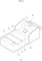
- FIG. 6 is a perspective view of a foot controller according to the embodiment.
- FIG. 7A is a top view of the foot controller according to the embodiment
- FIG. 7B is a side view of the foot controller according to the embodiment. Note that illustration of a kick switch (to be described later) on a right side face of the foot controller is omitted in FIG. 7B .
- the foot controller 26 includes a box-shaped housing 48, and is used for operating the endoscope holder 22.
- the foot controller 26 includes, on the top face of the housing 48, a placement part 50 on which a foot is to be placed, a first joystick 52, which is a first operating part, that can be operated back and forth and left and right by a foot placed at a first position P1 of the placement part 50, and a second joystick 54, which is a second operating part, that can be operated back and forth and left and right by a foot placed at a second position P2 of the placement part 50.
- the joysticks are of the type that can be relatively easily operated back and forth and left and right by a sole.
- the first joystick 52 and the second joystick 54 are arranged along the front-back direction on the placement part 50, and a predetermined operation of the endoscope holder 22 is selected in accordance with the direction of the operation on the first joystick 52 or the second joystick 54. While each joystick according to the embodiment is capable of being operated in at least four directions, the joysticks may be operating parts capable of being operated in more directions.
- the length D in the front-back direction of the placement part 50 is preferably larger than the foot length of a typical adult man and smaller than 400 mm. This minimizes the length D in the front-back direction of the foot controller 26.
- the width W of the foot controller 26 can be minimized.
- the width W is preferably larger than the foot width of a typical adult man and smaller than 250 mm.
- the height H is about 100 to 150 mm at a highest position of the foot controller 26.
- the user-friendliness of the foot controller 26 can be improved and the size of the entire foot controller 26 can be reduced.
- the back and forth and left and right operations of each joystick need not necessarily be set in such a manner that each of all the operations of the joystick is associated with selection of a predetermined operation of the endoscope holder 22, but some operations may be invalid, that is, some operations the joystick may be associated with none of the operations of the endoscope holder 22.
- FIG. 8A is a perspective view of the foot controller in a state in which a foot is placed at the first position of the placement part
- FIG. 8B is a side view of the foot controller in the state in which the foot is placed at the first position of the placement part
- FIG. 9A is a perspective view of the foot controller in a state in which a foot is placed at the second position of the placement part
- FIG. 9B is a side view of the foot controller in a state in which the foot is placed at the second position of the placement part. Note that illustration of the kick switch (to be described later) on the right side face of the foot controller is omitted in FIGS. 8B and 9B .
- the placement part 50 includes a first footrest 58 on which the heel 56a of a foot 56 placed at the first position P1 is placed, a second footrest 60 on which the heel 56a of a foot 56 placed at the second position P2 is placed, and a recess 62 at which the second joystick 54 is located.
- a groove 61 is formed between the first footrest 58 and the second footrest 60 so as to make it easier to recognize the position at which a foot is to be placed.
- the foot 56 placed at the first position P1 can operate the first joystick 52 with the bottom of the toes 56b.
- the second joystick 54 is located at a position that does not interfere with the foot 56 placed at the first position P1. As a result, it is unlikely that the second joystick 54 is erroneously touched while the first joystick 52 is being operated with the foot 56.
- the second joystick 54 is located at a position higher than the first joystick 52.
- a region of the placement part 50 in which the second joystick 54 is located has a tilted surface 64 with respect to an installation surface on which the foot controller 26 is installed, and the angle between the installation surface and the tilted surface 64 is ⁇ ° (see FIG. 7B ).
- ⁇ ° is an angle between 10° and 15°.
- a main surface of the placement part 50 and the installation surface are substantially parallel to each other.
- the foot 56 placed at the second position P2 has a toe-up posture and thus can operate the second joystick 54 with the bottom of the toes 56b.
- the first joystick 52 is located at the bottom of the recess 62 so that the first joystick 52 does not interfere with the foot 56 placed at the second position P2.
- FIG. 10 is a top view of the foot controller in a state in which a foot is placed on the placement part.
- the foot controller 26 further includes a kick switch 66, which is a third operating part, that is provided on a side of the placement part 50.
- the kick switch 66 is capable of being operated by a horizontal movement (in the direction of an arrow) of the foot 56 placed at the first position P1 and is also capable of being operated by a horizontal movement of the foot 56 placed at the second position P2.
- the kick switch 66 can be operated by a horizontal movement of the foot 56 both in the case where the foot 56 is placed at the first position P1 and in the case where the foot 56 is placed at the second position P2.
- the kick switch 66 is provided in a form of a pair of kick switches 66 at respective sides of the placement part 50, and the first joystick 52 and the second joystick 54 are arranged in a region between the pair of kick switches 66.
- the kick switch 66 can be operated by a horizontal movement of the foot 56 in either direction, which enables quick operation without a sense of discomfort as compared with a case where a kick switch is provided only on one side of the placement part 50 even if there is a difference in easiness of horizontal movement of a foot or a difference in easiness between a rightward movement and a leftward movement of a foot depending on the operator's dominant foot.
- FIG. 11 is a block diagram of the surgery assistance device 14 according to the embodiment.
- the surgery assistance device 14 includes the endoscope 24, the holding member 44 for holding the endoscope 24, the arm part 42 for adjusting the position of the holding member 44, the retracting mechanism 110, the monitor 38 for displaying a visual field image taken by the endoscope 24, the foot controller 26, and the controller 28 that changes the visual field image 46 in accordance with operations performed on the foot controller 26.
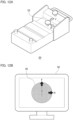
- FIG. 12A is a schematic diagram illustrating an operation of a first joystick
- FIG. 12B is a schematic diagram for explaining a change of a visual field image corresponding to the operation of the first joystick illustrated in FIG. 12A .
- a possible way is to change the orientation of the tip of the insertion portion 24a of the endoscope 24 back and forth and left and right.
- a drive controller 68 included in the controller 28 controls the movement of the endoscope 24 through the arm part 42 so that the visual field of the endoscope 24 in accordance with back and forth and left and right operations performed on the first joystick 52.
- the visual field of the visual field image 46 can be moved by tilting the endoscope 24 back and forth and left and right (FBLR) around a position at which the endoscope 24 is inserted into the eyeball 30.
- FBLR back and forth and left and right
- FIG. 13A is a schematic diagram illustrating an operation of a second joystick
- FIG. 13B is a schematic diagram for explaining a change of visual field image corresponding to the operation of the second joystick illustrated in FIG. 13A .
- a possible way is to advance and retract the endoscope 24 with respect to the eyeball 30.
- the drive controller 68 of the controller 28 controls the movement of the endoscope 24 through the arm part 42 so that the visual field of the endoscope 24 zooms in and out in accordance with the back and forth operation of the second joystick 54.
- the position of the endoscope 24 can be advanced and retracted (Zin, Zout) to cause the visual field image 46 to zoom in and out.
- an image processor 70 included in the controller 28 performs image processing so that the visual field image 46 turns in accordance with left and right operations of the second joystick 54.
- the visual field image resulting from image processing is displayed on the monitor 38 via an image generator 72.
- operation of the second joystick 54 is only needed to cause the visual field to zoom in and zoom out without regard to the movement of the endoscope 24, and the visual field image 46 can be turned by image processing without moving the endoscope 24.
- the visual field image 46 can be changed in accordance with the operation of the second joystick 54 on the foot controller 26 during interruption of manual work of the doctor 18, who is the operator, to change the visual field image 46 can be avoided.
- the surgery assistance device 14 When the kick switch 66 of the foot controller 26 is operated in an emergency, the surgery assistance device 14 according to the embodiment is capable of retracting the endoscope 24 from the eyeball 30 by the retracting mechanism 110 described above. In other words, in an emergency, the doctor 18 only needs to move his/her foot 56 horizontally to retract the endoscope 24 from the eyeball 30.
- the present invention can be used for a foot controller used to operate and control medical surgical tools during surgery.
Landscapes
- Health & Medical Sciences (AREA)
- Life Sciences & Earth Sciences (AREA)
- Surgery (AREA)
- Engineering & Computer Science (AREA)
- Public Health (AREA)
- Animal Behavior & Ethology (AREA)
- Biomedical Technology (AREA)
- Heart & Thoracic Surgery (AREA)
- Veterinary Medicine (AREA)
- General Health & Medical Sciences (AREA)
- Molecular Biology (AREA)
- Nuclear Medicine, Radiotherapy & Molecular Imaging (AREA)
- Medical Informatics (AREA)
- Biophysics (AREA)
- Physics & Mathematics (AREA)
- Ophthalmology & Optometry (AREA)
- Optics & Photonics (AREA)
- Pathology (AREA)
- Radiology & Medical Imaging (AREA)
- Robotics (AREA)
- Mechanical Engineering (AREA)
- Vascular Medicine (AREA)
- Multimedia (AREA)
- Endoscopes (AREA)
Abstract
Description
- The present invention relates to a foot controller, such as a foot controller used for operation and control of medical surgical tools during surgery.
- Pedals and foot controllers for operators, such as doctors and assistants, using surgical tools to perform part of operation and control of the surgical tools with their foot in various surgical operations have been devised. For example, Patent Literature 1 teaches a foot controller having a switch that enables operations in a first mode by being pressed down by toes and operations in a second mode by being pressed horizontally by a foot side.
- Patent Literature 1:
JP 2012-183382 A - According to the switch of the aforementioned foot controller, however, up to two operation modes can be selected with one switch. Thus, more switches will be needed for enabling selection of more operation modes, which makes the foot controller have a more complicated structure and a larger size. Furthermore, in operation of the aforementioned switch, the position of the foot that presses the switch to switch the mode needs to be changed, which may lower the user-friendliness. There is therefore room for further improvement in terms of reducing the operational burden and the operational errors of the operator.
- The present invention has been made in view of the aforementioned circumstances, and an exemplary object thereof is to provide a novel foot controller that is both space-saving and user-friendly.
- To solve the aforementioned problems, a foot controller according to an aspect of the present invention is a foot controller to be used for operation of a device and includes: a placement part on which a foot is to be placed; a first operating part capable of being operated back and forth and left and right by the foot placed at a first position of the placement part; and a second operating part capable of being operated back and forth and left and right by the foot placed at a second position of the placement part. On the placement part, the first operating part and the second operating part are arranged along a front-back direction, and a predetermined operation of the device is selected in accordance with a direction of an operation on the first operating part or the second operating part.
- According to this aspect, the foot controller can have a reduced width. Furthermore, because a number of operations of a device can be selected with two operating parts, the foot controller has improved user-friendliness and a reduced size. Note that the back and forth and left and right operations of each operating part need not necessarily be set in such a manner that each of all the operations of the operating part is associated with selection of a predetermined operation of the device, but some operations may be invalid, that is, some operations the operating part may be associated with none of the operations of the device.
- The first operating part may be located at a recess on the placement part, and the second operating part may be located at a position that does not interfere with the foot placed at the first position. As a result, it is unlikely that the second operating part is erroneously touched while the first operating part is being operated with a foot.
- The second operating part may be located at a higher position than the first operating part, and the first operating part may be located at a position that does not interfere with the foot placed at the second position. As a result, it is unlikely that the first operating part is erroneously touched while the second operating part is being operated with a foot.
- A third operating part on a side of the placement part may further be included. The third operating part may be capable of being operated by a horizontal movement of the foot placed at the first position and also capable of being operated by a horizontal movement of the foot placed at the second position. Thus, the third operating part can be operated by a horizontal movement of a foot both in the case where the foot is placed at the first position and in the case where the foot is placed at the second position.
- The third operating part may be a pair of switches at respective sides of the placement, and the first operating part and the second operating part may be located in a region between the pair of switches. Thus, a switch can be operated by a horizontal movement of the foot in either direction, which enables an operation without a sense of discomfort as compared with a case where a switch is provided only on one side of the placement part even if there is a difference in easiness of horizontal movement of a foot or a difference in easiness between a rightward movement and a leftward movement of a foot depending on the operator's dominant foot. This allows the foot controller to be operated by both of left and right feet.
- The first operating part and the second operating part may be joysticks. This allows relatively easy back and forth and left and right operations with a sole.
- Another aspect of the present invention is a surgery assistance device. The surgery assistance device includes: an endoscope; a holding member for holding the endoscope; an arm part for adjusting a position of the holding member; a display configured to display a visual field image taken by the endoscope; the aforementioned foot controller; and a controller configured to change the visual field image in accordance with an operation on the foot controller.
- According to this aspect, because the visual field image can be changed in accordance with the operation on the foot controller, interruption of manual work of the operator to change the visual field image can be avoided.
- The controller may include a drive controller configured to control movement of the endoscope through the arm part so that a visual field of the endoscope moves in accordance with a back/forth/left/right operation of the first operating part. Thus, the visual field can be moved without regard to the movement of the endoscope.
- The controller may include: a drive controller configured to control movement of the endoscope through the arm part so that the visual field of the endoscope zooms in and out in accordance with the back and forth operation of the second operating part; and an image processor configured to perform image processing so that the visual field image turns in accordance with a left/right operation of the second operating part. Thus, operation of the second operating part is only needed to cause the visual field to zoom in and out without regard to the movement of the endoscope, and the visual field image can be turned by image processing without moving the endoscope.
- Still another aspect of the present invention is a surgery assistance device. The surgery assistance device includes: an endoscope; a holding member for holding the endoscope; an arm part for adjusting a position of the holding member; a retracting mechanism for retracting the endoscope from an eyeball; and the aforementioned foot controller. When the third operating part on the foot controller is operated, the retracting mechanism retracts the endoscope from the eyeball.
- According to this aspect, in an emergency, the operator only needs to move his/her foot horizontally to retract the endoscope from an eyeball, for example.
- Note that any combination of the components described above, and any expression in the present invention converted to that for a method, a device, a system, and the like also remain as aspects of the present invention.
- According to the present invention, a foot controller that is both space-saving and user-friendly can be achieved.
-
-
FIG. 1A is a top view schematically illustrating a configuration of a surgical system, andFIG. 1B is a side view schematically illustrating the configuration of the surgical system. -
FIG. 2 is a diagram schematically illustrating a cross section structure of an eyeball. -
FIG. 3 is a schematic diagram illustrating a surgery assistance device according to the embodiment. -
FIG. 4 is a side view of an outline structure in a state in which an endoscope is inserted in an eyeball by a retracting mechanism according to the embodiment. -
FIG. 5 is a side view of an outline structure in a state in which the endoscope is retracted from the eyeball by the retracting mechanism according to the embodiment. -
FIG. 6 is a perspective view of a foot controller according to the embodiment. -
FIG. 7A is a top view of the foot controller according to the embodiment, andFIG. 7B is a side view of the foot controller according to the embodiment. -
FIG. 8A is a perspective view of the foot controller in a state in which a foot is placed at a first position of a placement part, andFIG. 8B is a side view of the foot controller in the state in which the foot is placed at the first position of the placement part. -
FIG. 9A is a perspective view of the foot controller in a state in which a foot is placed at a second position of the placement part, andFIG. 9B is a side view of the foot controller in a state in which the foot is placed at the second position of the placement part. -
FIG. 10 is a top view of the foot controller in a state in which a foot is placed on the placement part. -
FIG. 11 is a block diagram of a surgery assistance device according to the embodiment. -
FIG. 12A is a schematic diagram illustrating an operation of a first joystick, andFIG. 12B is a schematic diagram for explaining a change of visual field image corresponding to the operation of the first joystick illustrated inFIG. 12A . -
FIG. 13A is a schematic diagram illustrating an operation of a second joystick, andFIG. 13B is a schematic diagram for explaining a change of visual field image corresponding to the operation of the second joystick illustrated inFIG. 13A . - The present invention will now be described on the basis of an embodiment with reference to the drawings. Components, members, and processes that are the same as or equivalent to each other illustrated in the drawings are represented by the same reference numerals, and redundant explanation will not be repeated where appropriate. The embodiment is not to limit the invention, but is an example, and any feature or any combination of features described in the embodiment is not necessarily essential to the invention.
- An embodiment will be described below with reference to an example of a surgical system to be used in intraocular surgery.
FIG. 1A is a top view schematically illustrating a configuration of the surgical system, andFIG. 1B is a side view schematically illustrating the configuration of the surgical system.FIG. 2 is a diagram schematically illustrating a cross section structure of an eyeball.FIG. 3 is a schematic diagram illustrating a surgery assistance device according to the embodiment. - A
surgical system 10 illustrated inFIGS. 1A and 1B includes an operating table 12, and asurgery assistance device 14. Apatient 16, who is a subject of an operation, is laid on his/her back on the operating table 12. Adoctor 18, who is a surgeon, takes his/her position at the head of thepatient 16, and performs an operation inside an eyeball 30 (seeFIG. 2 ) of the patient 16 by using an operatingmicroscope 19 andvarious treatment tools 20. Examples of thetreatment tools 20 include a vitreous cutter, forceps, and an injector for irrigating solution or the like. - The surface of the
eyeball 30 illustrated inFIG. 2 is covered with acornea 31 and aconjunctiva 32, aniris 34 with a pupil 33 is present behind thecornea 31, and acrystalline lens 35 is present behind theiris 34. In addition, aretina 36 is present over an eyeground inside theeyeball 30. Thedoctor 18 performs an operation inside theeyeball 30 by inserting atreatment tool 20 into theconjunctiva 32, for example. - The operation on the
eyeball 30 performed by thedoctor 18 is assisted by thesurgery assistance device 14. Thesurgery assistance device 14 illustrated inFIG. 3 includes anendoscope holder 22, anendoscope 24, afoot controller 26, acontroller 28, and amonitor 38, which is a display. Theendoscope holder 22 includes abase part 40 and anarm part 42. Thebase part 40 is placed on a floor of an operating room or the like, and thearm part 42 is attached to thebase part 40. Thearm part 42 is turnably supported by thebase part 40. - The
arm part 42 is a mechanism including one or more joint portions and turnable portions and being capable of moving a holdingmember 44 at an arm distal end to an intended position with an intended posture. This enables control of the movement of theendoscope 24 held by the holdingmember 44 through thearm part 42. In other words, theendoscope 24 can be freely moved to any intended position by moving thearm part 42 with theendoscope 24 fixed to the holdingmember 44. - The
endoscope 24 inserted in theeyeball 30 of the patient 16 can be held by the holdingmember 44, which eliminates the need for thedoctor 18 to hold theendoscope 24 with a hand. Thedoctor 18 can therefore use both hands to perform the operation on theeyeball 30. - The
endoscope 24 of thesurgery assistance device 14 is inserted into theeyeball 30 in a state in which theendoscope 24 is fixed to the holding member 44 (seeFIG. 2 ). The state inside theeyeball 30 is imaged by the insertedendoscope 24. Image signals obtained by an image sensor of theendoscope 24 are converted through analog-to-digital conversion into digital image signals (image data) representing luminance of a predetermined number of gradations in units of pixels. An image based on the image data from theendoscope 24 is displayed on themonitor 38. - The
foot controller 26 is an operation device used for operation of the movement of theendoscope 24 through thearm part 42, and zooming in, zooming out, and rotation of an image, which was taken by theendoscope 24, displayed on themonitor 38, and the like. Some operating parts of thefoot controller 26 may be a joystick, a trackball, and a D-pad. - The
controller 28 performs various processes necessary for implementing thesurgery assistance device 14 according to the embodiment, such as control on the operation of thearm part 42, processes of generating various images to be displayed on themonitor 38, and processes of controlling the display on themonitor 38. - The
controller 28 includes a microcomputer including a central processing unit (CPU), a read only memory (ROM), a random access memory (RAM), and the like, for example. Thecontroller 28 is constituted by one or more microcomputers. Thecontroller 28 is included in thebase part 40 of theendoscope holder 22, for example. Alternatively, thecontroller 28 may be included in another external device. - The
monitor 38 displays avisual field image 46 of theendoscope 24 on the basis of the display control performed by thecontroller 28. A direction T toward the top is a direction opposite the gravitational direction, and the upward direction of thevisual field image 46 on themonitor 38 is adjusted to correspond to the direction T toward the top at initial settings. - Next, a retracting mechanism for retracting the endoscope inserted in the eyeball in an emergency will be described.
FIG. 4 is a side view of an outline structure in a state in which an endoscope is inserted in an eyeball by a retracting mechanism according to the embodiment.FIG. 5 is a side view of an outline structure in a state in which the endoscope is retracted from the eyeball by the retracting mechanism according to the embodiment. Note that the retracting mechanism according to the embodiment is provided between theendoscope 24 and thearm part 42. - The
retracting mechanism 110 illustrated inFIG. 4 includes the holdingmember 44 for holding theendoscope 24, which is a surgical tool, a guidingmember 116 for guiding the holdingmember 44 to linearly advance and retract, a lockingmember 120 for locking the position of the holdingmember 44 in a state in which theendoscope 24 is inserted in aneyeball 30, which is a surgical site, and aretracting unit 122 for releasing the locking state of the lockingmember 120 and retracting the holdingmember 44 in accordance with a signal from outside. - The
endoscope 24 includes a fiber-like insertion portion 24a having a diameter of about 0.5 to 1.2 mm to be inserted into aneyeball 30, agrip 24b, and acable 24c. Thegrip 24b is held by anadapter 44b of the holdingmember 44. The guidingmember 116 includes alinear guide 116a, and astage 116b configured to slide along thelinear guide 116a. - The retracting
unit 122 includes atension spring 124 that is a first force generating member for generating a first force F1 in a direction X in which the holdingmember 44 is to be retracted in a state in which the holdingmember 44 is locked, acompression spring 126 that is a second force generating member for generating a second force F2 for releasing the locking state of the lockingmember 120, and a pull-type solenoid 128 that is a third force generating member for generating a third force F3 for maintaining, against the second force F2, the locking state of the lockingmember 120. - A
first end 124a of thetension spring 124 is fixed to anend 44a in the retracting direction of the holdingmember 44. Asecond end 124b of thetension spring 124 is fixed to anend 116c of thelinear guide 116a. The lockingmember 120 is a rod-liketurnable member 120b configured to turn about afulcrum 120a in a Y direction. Theturnable member 120b has afirst end 120c that comes in contact with theend 44a of the holdingmember 44 and asecond end 120d on which the third force F3 acts in the locking state. - The pull-
type solenoid 128 pulls thesecond end 120d of theturnable member 120b while power is on. Specifically, the pull-type solenoid 128 has a hook-like catching portion 128a at an end of a plunger thereof. The catchingportion 128a fixes thesecond end 120d of theturnable member 120b in a state in which thesecond end 120d is pulled downward. - The
compression spring 126 of the retractingunit 122 according to the embodiment has a spring constant and a length set so that the locking state of the lockingmember 120 is released while power supply to the pull-type solenoid 128 is off. In addition, the retractingunit 122 further includes acontroller 28 for controlling power supply to the pull-type solenoid 128, asensor 132 for detecting the movement of theeyeball 30 or the movement of the head, and thefoot controller 26. - Next, an operation of immediately retracting the
endoscope 24 from theeyeball 30 in an X direction will be explained with reference toFIG. 5 . As illustrated inFIG. 5 , when the pull-type solenoid 128 is powered off, the third force F3 by which the catchingportion 128a of the pull-type solenoid 128 has pulled thesecond end 120d of theturnable member 120b downward is eliminated. As a result, thesecond end 120d is pushed upward and thefirst end 120c, which is located on a side opposite thesecond end 120d with respect to thefulcrum 120a, is pushed downward by the restoring force of thecompression spring 126, and the locking of the holdingmember 44 by the lockingmember 120 is thus released. - As a result, the restoring force of the
tension spring 124 with thefirst end 124a fixed to theend 44a of the holdingmember 44 moves the holdingmember 44 in the X direction, and theendoscope 24 is retracted from theeyeball 30 in the X direction. - As described above, the
retracting mechanism 110 according to the embodiment allows theendoscope 24 linearly inserted in theeyeball 30, which is the surgical site, along thelinear guide 116a to be retracted in parallel (in the X direction) with the inserting direction Z of theendoscope 24. As a result, the load applied to theeyeball 30 while theendoscope 24 is retracted from theeyeball 30 is reduced. - In addition, the
retracting mechanism 110 achieves holding and retraction of theendoscope 24 by adjusting the forces generated by thetension spring 124, thecompression spring 126, and the pull-type solenoid 128 by a simple structure. - In addition, in the
retracting mechanism 110, because the pull-type solenoid 128 that requires power supply and a relatively large space can be placed at a position away from the holdingmember 44, the flexibility of layout of respective components is increased without making the structure complicated. - Furthermore, in such an emergency in which power supply to the pull-
type solenoid 128 is cut off owing to a power failure or a device failure, for example, theretracting mechanism 110 is capable of quickly retracting theendoscope 24 from theeyeball 30 without requiring special control. In addition, theretracting mechanism 110 is capable of generating the second force F2 by the restoring force of thecompression spring 126 without using power, and similarly capable of generating the first force F1 by the restoring force of thetension spring 124 without using power. - Furthermore, in an emergency, the
retracting mechanism 110 is capable of quickly retracting theendoscope 24 inserted in such a soft and delicate surgical site as theeyeball 30 while reducing the load applied to theeyeball 30. - In addition, the
controller 28 of the retractingunit 122 according to the embodiment is configured to release the locking state of the lockingmember 120 by controlling current to turn off power supply to the pull-type solenoid 128 in accordance with a signal in response to a movement of the eyeball or the like detected by thesensor 132. This allows theendoscope 24 held in a state inserted in theeyeball 30 to be quickly retracted before a large load is applied to theeyeball 30 by the movement of the position of theeyeball 30. - While the retracting
unit 122 according to the embodiment is a combination of thecompression spring 126, which is the second force generating member, and the pull-type solenoid 128, which is the third force generating member, a retracting unit may be configured as a combination of a tension spring, as a second force generating member, for pulling theturnable member 120b upward and a push-type solenoid, as a third force generating member, for pushing thesecond end 120d of theturnable member 120b downward when power is supplied to the push-type solenoid. - Next, a foot controller according to the embodiment will be described in detail.
FIG. 6 is a perspective view of a foot controller according to the embodiment.FIG. 7A is a top view of the foot controller according to the embodiment, andFIG. 7B is a side view of the foot controller according to the embodiment. Note that illustration of a kick switch (to be described later) on a right side face of the foot controller is omitted inFIG. 7B . - The
foot controller 26 includes a box-shapedhousing 48, and is used for operating theendoscope holder 22. Specifically, thefoot controller 26 includes, on the top face of thehousing 48, aplacement part 50 on which a foot is to be placed, afirst joystick 52, which is a first operating part, that can be operated back and forth and left and right by a foot placed at a first position P1 of theplacement part 50, and asecond joystick 54, which is a second operating part, that can be operated back and forth and left and right by a foot placed at a second position P2 of theplacement part 50. The joysticks are of the type that can be relatively easily operated back and forth and left and right by a sole. - The
first joystick 52 and thesecond joystick 54 are arranged along the front-back direction on theplacement part 50, and a predetermined operation of theendoscope holder 22 is selected in accordance with the direction of the operation on thefirst joystick 52 or thesecond joystick 54. While each joystick according to the embodiment is capable of being operated in at least four directions, the joysticks may be operating parts capable of being operated in more directions. - The length D in the front-back direction of the
placement part 50 is preferably larger than the foot length of a typical adult man and smaller than 400 mm. This minimizes the length D in the front-back direction of thefoot controller 26. In addition, because the two joysticks are arranged along the front-back direction, the width W of thefoot controller 26 can be minimized. The width W is preferably larger than the foot width of a typical adult man and smaller than 250 mm. The height H is about 100 to 150 mm at a highest position of thefoot controller 26. - Because a number of operations of the
endoscope holder 22 can be selected with two joysticks, the user-friendliness of thefoot controller 26 according to the embodiment can be improved and the size of theentire foot controller 26 can be reduced. Note that the back and forth and left and right operations of each joystick need not necessarily be set in such a manner that each of all the operations of the joystick is associated with selection of a predetermined operation of theendoscope holder 22, but some operations may be invalid, that is, some operations the joystick may be associated with none of the operations of theendoscope holder 22. -
FIG. 8A is a perspective view of the foot controller in a state in which a foot is placed at the first position of the placement part, andFIG. 8B is a side view of the foot controller in the state in which the foot is placed at the first position of the placement part.FIG. 9A is a perspective view of the foot controller in a state in which a foot is placed at the second position of the placement part, andFIG. 9B is a side view of the foot controller in a state in which the foot is placed at the second position of the placement part. Note that illustration of the kick switch (to be described later) on the right side face of the foot controller is omitted inFIGS. 8B and9B . - The
placement part 50 includes afirst footrest 58 on which theheel 56a of afoot 56 placed at the first position P1 is placed, asecond footrest 60 on which theheel 56a of afoot 56 placed at the second position P2 is placed, and arecess 62 at which thesecond joystick 54 is located. Agroove 61 is formed between thefirst footrest 58 and thesecond footrest 60 so as to make it easier to recognize the position at which a foot is to be placed. - As illustrated in
FIGS. 8A and 8B , thefoot 56 placed at the first position P1 can operate thefirst joystick 52 with the bottom of thetoes 56b. In this state, thesecond joystick 54 is located at a position that does not interfere with thefoot 56 placed at the first position P1. As a result, it is unlikely that thesecond joystick 54 is erroneously touched while thefirst joystick 52 is being operated with thefoot 56. - According to the
foot controller 26 according to the embodiment, thesecond joystick 54 is located at a position higher than thefirst joystick 52. In addition, a region of theplacement part 50 in which thesecond joystick 54 is located has a tiltedsurface 64 with respect to an installation surface on which thefoot controller 26 is installed, and the angle between the installation surface and the tiltedsurface 64 is α° (seeFIG. 7B ). Note that α° is an angle between 10° and 15°. In addition, a main surface of theplacement part 50 and the installation surface are substantially parallel to each other. - As a result, as illustrated in
FIGS. 9A and 9B , thefoot 56 placed at the second position P2 has a toe-up posture and thus can operate thesecond joystick 54 with the bottom of thetoes 56b. In this state, thefirst joystick 52 is located at the bottom of therecess 62 so that thefirst joystick 52 does not interfere with thefoot 56 placed at the second position P2. As a result, it is unlikely that thefirst joystick 52 is erroneously touched while thesecond joystick 54 is being operated with thefoot 56. -
FIG. 10 is a top view of the foot controller in a state in which a foot is placed on the placement part. Thefoot controller 26 further includes akick switch 66, which is a third operating part, that is provided on a side of theplacement part 50. As illustrated inFIG. 10 , thekick switch 66 is capable of being operated by a horizontal movement (in the direction of an arrow) of thefoot 56 placed at the first position P1 and is also capable of being operated by a horizontal movement of thefoot 56 placed at the second position P2. Thus, thekick switch 66 can be operated by a horizontal movement of thefoot 56 both in the case where thefoot 56 is placed at the first position P1 and in the case where thefoot 56 is placed at the second position P2. - In the embodiment, the
kick switch 66 is provided in a form of a pair of kick switches 66 at respective sides of theplacement part 50, and thefirst joystick 52 and thesecond joystick 54 are arranged in a region between the pair of kick switches 66. Thus, thekick switch 66 can be operated by a horizontal movement of thefoot 56 in either direction, which enables quick operation without a sense of discomfort as compared with a case where a kick switch is provided only on one side of theplacement part 50 even if there is a difference in easiness of horizontal movement of a foot or a difference in easiness between a rightward movement and a leftward movement of a foot depending on the operator's dominant foot. This allows thefoot controller 26 to be operated by both of left and right feet. -
FIG. 11 is a block diagram of thesurgery assistance device 14 according to the embodiment. As described above, thesurgery assistance device 14 according to the embodiment includes theendoscope 24, the holdingmember 44 for holding theendoscope 24, thearm part 42 for adjusting the position of the holdingmember 44, theretracting mechanism 110, themonitor 38 for displaying a visual field image taken by theendoscope 24, thefoot controller 26, and thecontroller 28 that changes thevisual field image 46 in accordance with operations performed on thefoot controller 26. -
FIG. 12A is a schematic diagram illustrating an operation of a first joystick, andFIG. 12B is a schematic diagram for explaining a change of a visual field image corresponding to the operation of the first joystick illustrated inFIG. 12A . In order to move the visual field on thevisual field image 46 back and forth and left and right, a possible way is to change the orientation of the tip of theinsertion portion 24a of theendoscope 24 back and forth and left and right. - Thus, a
drive controller 68 included in thecontroller 28 controls the movement of theendoscope 24 through thearm part 42 so that the visual field of theendoscope 24 in accordance with back and forth and left and right operations performed on thefirst joystick 52. For example, as illustrated inFIG. 2 , the visual field of thevisual field image 46 can be moved by tilting theendoscope 24 back and forth and left and right (FBLR) around a position at which theendoscope 24 is inserted into theeyeball 30. Thus, because thevisual field image 46 can be changed in accordance with the operation of thefirst joystick 52 on thefoot controller 26, interruption of manual work of thedoctor 18, who is the operator, to change thevisual field image 46 can be avoided. -
FIG. 13A is a schematic diagram illustrating an operation of a second joystick, andFIG. 13B is a schematic diagram for explaining a change of visual field image corresponding to the operation of the second joystick illustrated inFIG. 13A . For zooming in and zooming out of the visual field on thevisual field image 46, a possible way is to advance and retract theendoscope 24 with respect to theeyeball 30. - Thus, the
drive controller 68 of thecontroller 28 controls the movement of theendoscope 24 through thearm part 42 so that the visual field of theendoscope 24 zooms in and out in accordance with the back and forth operation of thesecond joystick 54. For example, as illustrated inFIG. 2 , the position of theendoscope 24 can be advanced and retracted (Zin, Zout) to cause thevisual field image 46 to zoom in and out. - In addition, an
image processor 70 included in thecontroller 28 performs image processing so that thevisual field image 46 turns in accordance with left and right operations of thesecond joystick 54. The visual field image resulting from image processing is displayed on themonitor 38 via animage generator 72. - Thus, operation of the
second joystick 54 is only needed to cause the visual field to zoom in and zoom out without regard to the movement of theendoscope 24, and thevisual field image 46 can be turned by image processing without moving theendoscope 24. In other words, because thevisual field image 46 can be changed in accordance with the operation of thesecond joystick 54 on thefoot controller 26, interruption of manual work of thedoctor 18, who is the operator, to change thevisual field image 46 can be avoided. - When the
kick switch 66 of thefoot controller 26 is operated in an emergency, thesurgery assistance device 14 according to the embodiment is capable of retracting theendoscope 24 from theeyeball 30 by theretracting mechanism 110 described above. In other words, in an emergency, thedoctor 18 only needs to move his/herfoot 56 horizontally to retract theendoscope 24 from theeyeball 30. - While the present invention has been described above with reference to the embodiment, the present invention is not limited to the embodiment, and any combination or substitution of components in the embodiment as appropriate is included in the present invention. In addition, modifications such as combinations, changes in the order of processes, and various changes in design in the embodiment may be made on the embodiment on the basis of knowledge of a person skilled in the art, and such modified embodiments may be within the scope of the present invention.
- The present invention can be used for a foot controller used to operate and control medical surgical tools during surgery.
-
- 10
- surgical system
- 12
- operating table
- 14
- surgery assistance device
- 16
- patient
- 18
- doctor
- 20
- treatment tool
- 22
- endoscope holder
- 24
- endoscope
- 26
- foot controller
- 28
- controller
- 30
- eyeball
- 38
- monitor
- 40
- base part
- 42
- arm part
- 44
- holding member
- 46
- endoscopic image
- 48
- housing
- 50
- placement part
- 52
- first joystick
- 54
- second joystick
- 56
- foot
- 62
- recess
- 66
- kick switch
- 68
- drive controller
- 70
- image processor
- 110
- retracting mechanism
Claims (10)
- A foot controller to be used for operation of a device, the foot controller comprising:a placement part on which a foot is to be placed;a first operating part capable of being operated back and forth and left and right by the foot placed at a first position of the placement part; anda second operating part capable of being operated back and forth and left and right by the foot placed at a second position of the placement part, whereinon the placement part, the first operating part and the second operating part are arranged along a front-back direction, anda predetermined operation of the device is selected in accordance with a direction of an operation on the first operating part or the second operating part.
- The foot controller according to claim 1, whereinthe first operating part is located at a recess on the placement part, andthe second operating part is located at a position that does not interfere with the foot placed at the first position.
- The foot controller according to claim 2, whereinthe second operating part is located at a higher position than the first operating part, andthe first operating part is located at a position that does not interfere with the foot placed at the second position.
- The foot controller according to any one of claims 1 to 3, further comprising:a third operating part on a side of the placement part, whereinthe third operating part is capable of being operated by a horizontal movement of the foot placed at the first position and also capable of being operated by a horizontal movement of the foot placed at the second position.
- The foot controller according to claim 4, whereinthe third operating part is a pair of switches at respective sides of the placement, andthe first operating part and the second operating part are located in a region between the pair of switches.
- The foot controller according to any one of claims 1 to 5, wherein
the first operating part and the second operating part are joysticks. - A surgery assistance device comprising:an endoscope;a holding member for holding the endoscope;an arm part for adjusting a position of the holding member;a display configured to display a visual field image taken by the endoscope;the foot controller according to any one of claims 1 to 6; anda controller configured to change the visual field image in accordance with an operation on the foot controller.
- The surgery assistance device according to claim 7, wherein
the controller includes a drive controller configured to control movement of the endoscope through the arm part so that a visual field of the endoscope moves in accordance with a back/forth/left/right operation of the first operating part. - The surgery assistance device according to claim 7 or 8, wherein
the controller includes:a drive controller configured to control movement of the endoscope through the arm part so that the visual field of the endoscope zooms in and out in accordance with the back and forth operation of the second operating part; andan image processor configured to perform image processing so that the visual field image turns in accordance with a left/right operation of the second operating part. - A surgery assistance device comprising:an endoscope;a holding member for holding the endoscope;an arm part for adjusting a position of the holding member;a retracting mechanism for retracting the endoscope from an eyeball; andthe foot controller according to claim 4 or 5, whereinwhen the third operating part on the foot controller is operated, the retracting mechanism retracts the endoscope from the eyeball.
Applications Claiming Priority (2)
| Application Number | Priority Date | Filing Date | Title |
|---|---|---|---|
| JP2021175185A JP7320296B6 (en) | 2021-10-27 | 2021-10-27 | Surgery support device |
| PCT/JP2022/021762 WO2023074033A1 (en) | 2021-10-27 | 2022-05-27 | Foot controller and surgery assistance device |
Publications (3)
| Publication Number | Publication Date |
|---|---|
| EP4424264A1 true EP4424264A1 (en) | 2024-09-04 |
| EP4424264A4 EP4424264A4 (en) | 2025-01-01 |
| EP4424264B1 EP4424264B1 (en) | 2025-12-24 |
Family
ID=86159698
Family Applications (1)
| Application Number | Title | Priority Date | Filing Date |
|---|---|---|---|
| EP22886370.0A Active EP4424264B1 (en) | 2021-10-27 | 2022-05-27 | Foot controller and surgery assistance device |
Country Status (5)
| Country | Link |
|---|---|
| US (1) | US20240268629A1 (en) |
| EP (1) | EP4424264B1 (en) |
| JP (1) | JP7320296B6 (en) |
| CN (1) | CN117479901A (en) |
| WO (1) | WO2023074033A1 (en) |
Family Cites Families (13)
| Publication number | Priority date | Publication date | Assignee | Title |
|---|---|---|---|---|
| US5524180A (en) * | 1992-08-10 | 1996-06-04 | Computer Motion, Inc. | Automated endoscope system for optimal positioning |
| JP2002153487A (en) * | 2000-11-17 | 2002-05-28 | Topcon Corp | microscope |
| JP4426770B2 (en) * | 2003-03-12 | 2010-03-03 | オリンパス株式会社 | Endoscope holding device |
| JP4472365B2 (en) * | 2004-01-23 | 2010-06-02 | オリンパス株式会社 | Medical instrument holding device |
| US7626132B2 (en) | 2005-10-13 | 2009-12-01 | Alcon, Inc. | Foot controller |
| JP6021353B2 (en) * | 2011-08-04 | 2016-11-09 | オリンパス株式会社 | Surgery support device |
| DE102013015109A1 (en) * | 2013-09-12 | 2015-03-12 | Carl Zeiss Meditec Ag | Control panel for a medical device and operating unit for such a control panel |
| WO2018100828A1 (en) * | 2016-11-29 | 2018-06-07 | ソニー・オリンパスメディカルソリューションズ株式会社 | Microscope device and control method |
| US10368955B2 (en) * | 2017-03-31 | 2019-08-06 | Johnson & Johnson Innovation-Jjdc, Inc. | Multi-functional foot pedal assembly for controlling a robotic surgical system |
| JP6599402B2 (en) * | 2017-06-08 | 2019-10-30 | 株式会社メディカロイド | Remote control device |
| JP6622872B2 (en) * | 2018-02-05 | 2019-12-18 | ミーレ カンパニー インク. | Master console for surgical robot |
| JP7814832B2 (en) * | 2019-03-27 | 2026-02-17 | 三菱電機株式会社 | Robot, input unit, remote control device, and robot remote control system |
| KR102317460B1 (en) * | 2020-03-17 | 2021-10-27 | 주식회사 엠케어코리아 | Foot switch and medical system having the same |
-
2021
- 2021-10-27 JP JP2021175185A patent/JP7320296B6/en active Active
-
2022
- 2022-05-27 WO PCT/JP2022/021762 patent/WO2023074033A1/en not_active Ceased
- 2022-05-27 EP EP22886370.0A patent/EP4424264B1/en active Active
- 2022-05-27 CN CN202280041847.7A patent/CN117479901A/en active Pending
-
2024
- 2024-04-26 US US18/646,988 patent/US20240268629A1/en active Pending
Also Published As
| Publication number | Publication date |
|---|---|
| JP2023064818A (en) | 2023-05-12 |
| US20240268629A1 (en) | 2024-08-15 |
| JP7320296B6 (en) | 2023-09-05 |
| CN117479901A (en) | 2024-01-30 |
| JP7320296B2 (en) | 2023-08-03 |
| EP4424264B1 (en) | 2025-12-24 |
| WO2023074033A1 (en) | 2023-05-04 |
| EP4424264A4 (en) | 2025-01-01 |
Similar Documents
| Publication | Publication Date | Title |
|---|---|---|
| JP7155344B2 (en) | Surgical system and display method | |
| JP6585613B2 (en) | Structure adjustment system and method for teleoperated medical system | |
| US20230240765A1 (en) | Remote control apparatus | |
| JP6546361B1 (en) | Surgery support device | |
| JP2020044354A (en) | Remote operation device and remote operation system | |
| JP2020032162A (en) | Adaptor | |
| EP4527336A1 (en) | Operating system and method for ercp surgical robot | |
| JP2020031770A (en) | Driving part interface | |
| CN112107368A (en) | Surgeon input device for minimally invasive surgery | |
| EP3603562B1 (en) | Medical observation apparatus and observation field correction method | |
| EP4424264A1 (en) | Foot controller and surgery assistance device | |
| JP6745392B2 (en) | Remote control device | |
| JP7128326B2 (en) | surgery system | |
| JP2020032161A (en) | Driving part interface, adapter, mounting detection method for surgical instrument to driving part interface | |
| WO2018225818A1 (en) | Remote operation device, display device, remote operation system, surgery assistance system, and method for exchanging display device of remote operation device | |
| KR20120057233A (en) | Surgical instrument system | |
| JP7350910B2 (en) | Operation pedal device and remote control device | |
| KR101784305B1 (en) | Master device and handle thereof, and conrolling method of the master device for interventional procedure, and remote control interventional procedure device using the master device | |
| JP6665263B2 (en) | Remote control device, surgical system and method for specifying pedal to be operated | |
| JP2020031774A (en) | Surgical instrument | |
| WO2023171263A1 (en) | Control device and medical robot | |
| CN118948450A (en) | Surgical robot and surgical system | |
| JP2026513052A (en) | Upper respiratory tract access | |
| JPS63194659A (en) | Chair for endoscope apparatus | |
| CN118680687A (en) | A kind of slave operation device of surgical robot |
Legal Events
| Date | Code | Title | Description |
|---|---|---|---|
| STAA | Information on the status of an ep patent application or granted ep patent |
Free format text: STATUS: THE INTERNATIONAL PUBLICATION HAS BEEN MADE |
|
| PUAI | Public reference made under article 153(3) epc to a published international application that has entered the european phase |
Free format text: ORIGINAL CODE: 0009012 |
|
| STAA | Information on the status of an ep patent application or granted ep patent |
Free format text: STATUS: REQUEST FOR EXAMINATION WAS MADE |
|
| 17P | Request for examination filed |
Effective date: 20240527 |
|
| AK | Designated contracting states |
Kind code of ref document: A1 Designated state(s): AL AT BE BG CH CY CZ DE DK EE ES FI FR GB GR HR HU IE IS IT LI LT LU LV MC MK MT NL NO PL PT RO RS SE SI SK SM TR |
|
| A4 | Supplementary search report drawn up and despatched |
Effective date: 20241204 |
|
| RIC1 | Information provided on ipc code assigned before grant |
Ipc: A61B 1/00 20060101ALN20241128BHEP Ipc: B25J 3/00 20060101ALI20241128BHEP Ipc: A61F 9/007 20060101ALI20241128BHEP Ipc: A61B 34/37 20160101AFI20241128BHEP |
|
| DAV | Request for validation of the european patent (deleted) | ||
| DAX | Request for extension of the european patent (deleted) | ||
| RAP3 | Party data changed (applicant data changed or rights of an application transferred) |
Owner name: RIVERFIELD INC. |
|
| GRAP | Despatch of communication of intention to grant a patent |
Free format text: ORIGINAL CODE: EPIDOSNIGR1 |
|
| STAA | Information on the status of an ep patent application or granted ep patent |
Free format text: STATUS: GRANT OF PATENT IS INTENDED |
|
| RIC1 | Information provided on ipc code assigned before grant |
Ipc: A61B 34/37 20160101AFI20250730BHEP Ipc: A61F 9/007 20060101ALI20250730BHEP Ipc: B25J 3/00 20060101ALI20250730BHEP Ipc: A61B 1/00 20060101ALN20250730BHEP |
|
| INTG | Intention to grant announced |
Effective date: 20250811 |
|
| RIN1 | Information on inventor provided before grant (corrected) |
Inventor name: FUKUDA, TATSUHITO Inventor name: SONODA, KOH-HEI |
|
| GRAS | Grant fee paid |
Free format text: ORIGINAL CODE: EPIDOSNIGR3 |
|
| GRAA | (expected) grant |
Free format text: ORIGINAL CODE: 0009210 |
|
| STAA | Information on the status of an ep patent application or granted ep patent |
Free format text: STATUS: THE PATENT HAS BEEN GRANTED |
|
| AK | Designated contracting states |
Kind code of ref document: B1 Designated state(s): AL AT BE BG CH CY CZ DE DK EE ES FI FR GB GR HR HU IE IS IT LI LT LU LV MC MK MT NL NO PL PT RO RS SE SI SK SM TR |
|
| REG | Reference to a national code |
Ref country code: CH Ref legal event code: F10 Free format text: ST27 STATUS EVENT CODE: U-0-0-F10-F00 (AS PROVIDED BY THE NATIONAL OFFICE) Effective date: 20251224 Ref country code: GB Ref legal event code: FG4D |
|
| REG | Reference to a national code |
Ref country code: DE Ref legal event code: R096 Ref document number: 602022027630 Country of ref document: DE |
|
| P01 | Opt-out of the competence of the unified patent court (upc) registered |
Free format text: CASE NUMBER: UPC_APP_0017614_4424264/2025 Effective date: 20251215 |
|
| PGFP | Annual fee paid to national office [announced via postgrant information from national office to epo] |
Ref country code: GB Payment date: 20260324 Year of fee payment: 5 |
|
| REG | Reference to a national code |
Ref country code: LT Ref legal event code: MG9D |
|
| PG25 | Lapsed in a contracting state [announced via postgrant information from national office to epo] |
Ref country code: NO Free format text: LAPSE BECAUSE OF FAILURE TO SUBMIT A TRANSLATION OF THE DESCRIPTION OR TO PAY THE FEE WITHIN THE PRESCRIBED TIME-LIMIT Effective date: 20260324 |
|
| PG25 | Lapsed in a contracting state [announced via postgrant information from national office to epo] |
Ref country code: FI Free format text: LAPSE BECAUSE OF FAILURE TO SUBMIT A TRANSLATION OF THE DESCRIPTION OR TO PAY THE FEE WITHIN THE PRESCRIBED TIME-LIMIT Effective date: 20251224 Ref country code: HR Free format text: LAPSE BECAUSE OF FAILURE TO SUBMIT A TRANSLATION OF THE DESCRIPTION OR TO PAY THE FEE WITHIN THE PRESCRIBED TIME-LIMIT Effective date: 20251224 |
|
| PG25 | Lapsed in a contracting state [announced via postgrant information from national office to epo] |
Ref country code: RS Free format text: LAPSE BECAUSE OF FAILURE TO SUBMIT A TRANSLATION OF THE DESCRIPTION OR TO PAY THE FEE WITHIN THE PRESCRIBED TIME-LIMIT Effective date: 20260324 |
|
| PG25 | Lapsed in a contracting state [announced via postgrant information from national office to epo] |
Ref country code: LV Free format text: LAPSE BECAUSE OF FAILURE TO SUBMIT A TRANSLATION OF THE DESCRIPTION OR TO PAY THE FEE WITHIN THE PRESCRIBED TIME-LIMIT Effective date: 20251224 |