EP4424239A1 - Bereitstellung von poseneinstellungsinformationen - Google Patents
Bereitstellung von poseneinstellungsinformationen Download PDFInfo
- Publication number
- EP4424239A1 EP4424239A1 EP23159085.2A EP23159085A EP4424239A1 EP 4424239 A1 EP4424239 A1 EP 4424239A1 EP 23159085 A EP23159085 A EP 23159085A EP 4424239 A1 EP4424239 A1 EP 4424239A1
- Authority
- EP
- European Patent Office
- Prior art keywords
- anatomical structure
- pose
- projection
- image
- ray
- Prior art date
- Legal status (The legal status is an assumption and is not a legal conclusion. Google has not performed a legal analysis and makes no representation as to the accuracy of the status listed.)
- Withdrawn
Links
Images


Classifications
-
- A—HUMAN NECESSITIES
- A61—MEDICAL OR VETERINARY SCIENCE; HYGIENE
- A61B—DIAGNOSIS; SURGERY; IDENTIFICATION
- A61B6/00—Apparatus or devices for radiation diagnosis; Apparatus or devices for radiation diagnosis combined with radiation therapy equipment
- A61B6/04—Positioning of patients; Tiltable beds or the like
-
- A—HUMAN NECESSITIES
- A61—MEDICAL OR VETERINARY SCIENCE; HYGIENE
- A61B—DIAGNOSIS; SURGERY; IDENTIFICATION
- A61B6/00—Apparatus or devices for radiation diagnosis; Apparatus or devices for radiation diagnosis combined with radiation therapy equipment
- A61B6/50—Apparatus or devices for radiation diagnosis; Apparatus or devices for radiation diagnosis combined with radiation therapy equipment specially adapted for specific body parts; specially adapted for specific clinical applications
- A61B6/505—Apparatus or devices for radiation diagnosis; Apparatus or devices for radiation diagnosis combined with radiation therapy equipment specially adapted for specific body parts; specially adapted for specific clinical applications for diagnosis of bone
-
- G—PHYSICS
- G06—COMPUTING OR CALCULATING; COUNTING
- G06N—COMPUTING ARRANGEMENTS BASED ON SPECIFIC COMPUTATIONAL MODELS
- G06N3/00—Computing arrangements based on biological models
- G06N3/02—Neural networks
- G06N3/04—Architecture, e.g. interconnection topology
- G06N3/044—Recurrent networks, e.g. Hopfield networks
- G06N3/0442—Recurrent networks, e.g. Hopfield networks characterised by memory or gating, e.g. long short-term memory [LSTM] or gated recurrent units [GRU]
-
- G—PHYSICS
- G06—COMPUTING OR CALCULATING; COUNTING
- G06N—COMPUTING ARRANGEMENTS BASED ON SPECIFIC COMPUTATIONAL MODELS
- G06N3/00—Computing arrangements based on biological models
- G06N3/02—Neural networks
- G06N3/04—Architecture, e.g. interconnection topology
- G06N3/0464—Convolutional networks [CNN, ConvNet]
-
- G—PHYSICS
- G06—COMPUTING OR CALCULATING; COUNTING
- G06N—COMPUTING ARRANGEMENTS BASED ON SPECIFIC COMPUTATIONAL MODELS
- G06N3/00—Computing arrangements based on biological models
- G06N3/02—Neural networks
- G06N3/08—Learning methods
- G06N3/084—Backpropagation, e.g. using gradient descent
-
- G—PHYSICS
- G06—COMPUTING OR CALCULATING; COUNTING
- G06N—COMPUTING ARRANGEMENTS BASED ON SPECIFIC COMPUTATIONAL MODELS
- G06N3/00—Computing arrangements based on biological models
- G06N3/02—Neural networks
- G06N3/08—Learning methods
- G06N3/09—Supervised learning
-
- G—PHYSICS
- G06—COMPUTING OR CALCULATING; COUNTING
- G06T—IMAGE DATA PROCESSING OR GENERATION, IN GENERAL
- G06T7/00—Image analysis
- G06T7/70—Determining position or orientation of objects or cameras
- G06T7/73—Determining position or orientation of objects or cameras using feature-based methods
-
- G—PHYSICS
- G06—COMPUTING OR CALCULATING; COUNTING
- G06N—COMPUTING ARRANGEMENTS BASED ON SPECIFIC COMPUTATIONAL MODELS
- G06N3/00—Computing arrangements based on biological models
- G06N3/02—Neural networks
- G06N3/04—Architecture, e.g. interconnection topology
- G06N3/045—Combinations of networks
- G06N3/0455—Auto-encoder networks; Encoder-decoder networks
Definitions
- the present disclosure relates to providing pose adjustment information for adjusting a pose of an anatomical structure with respect to a projection X-ray imaging system in order to acquire a target X-ray projection image.
- a computer-implemented method, a computer program product, and a system, are disclosed.
- Projection X-ray imaging systems include an X-ray source and an X-ray detector.
- the X-ray source and the X-ray detector are separated by an examination region.
- an anatomical structure such as an ankle, a leg or a chest of a subject, is disposed in the examination region in order to generate X-ray projection images representing the anatomical structure.
- the positioning of anatomical structures in order to acquire X-ray projection images is conventionally performed based on the experience of an operator.
- the operator may position the patient by eye, sometimes via a monitor that displays a visible camera image of the object.
- the operator uses their experience to adjust the pose, i.e. the position and orientation, of the anatomical structure, in order to try to provide a requested image of the anatomical structure.
- Markings on the X-ray detector that indicate the extent of an X-ray detector's radiation-sensitive region are used to ensure that the anatomical structure is correctly positioned with respect to the X-ray detector prior to acquiring the image.
- a document WO 2019/134874 A1 discloses that the appropriate positioning of a patient in an X-ray imaging system can present difficulties for medical professional owing, on one hand to the small size of important anatomical aspects which need to be captured in X-ray images, and on the other hand to the significant movements in a field of view presented by a typical patient.
- This document proposes to obtain an image of the position of a patient in the field of view at approximately the same time that an initial X-ray image is obtained. If it proves necessary to obtain a subsequent X-ray image with updated field of view settings (for example, collimation parameters), the movement of the patient at the point of taking the second image is factored into the provision of updated field of view settings.
- updated field of view settings for example, collimation parameters
- a computer-implemented method of providing pose adjustment information for adjusting a pose of an anatomical structure with respect to a projection X-ray imaging system in order to acquire a target X-ray projection image representing the anatomical structure includes:
- the above method provides pose adjustment information that can be used to adjust an initial pose of an anatomical structure with respect to the projection X-ray imaging system in order to acquire a target X-ray projection image representing the anatomical structure, or in other words, a desired image. Since, in the above method, the pose adjustment information is generated by a neural network, the pose adjustment information may be generated in a reliable manner. This has the advantage of reducing the number of re-takes of the image, thereby reducing X-ray dose to a subject and improving workflow.
- the pose adjustment information is generated using an initial X-ray projection image and a camera image representing the anatomical structure.
- reliable pose adjustment information may be provided since the neural network generates the pose adjustment information using two complementary sources of image data, i.e. an X-ray projection image and a camera image.
- the pose adjustment information is generated using a camera image representing the anatomical structure and without the use of an initial X-ray projection image.
- X-ray dose to the subject may be further reduced.
- the pose adjustment information includes an adjustment to an absolute position and/or an absolute orientation of the anatomical structure.
- the anatomical structure is adjusted rather than the projection X-ray imaging system.
- the projection X-ray imaging system remains static, and consequently the desired image may be acquired in a more efficient manner, thereby improving workflow.
- a computer-implemented method of providing pose adjustment information for adjusting a pose of an anatomical structure with respect to a projection X-ray imaging system in order to acquire a target X-ray projection image representing the anatomical structure includes:
- This method provides pose adjustment information that may be used to adjust an initial pose of an anatomical structure with respect to the projection X-ray imaging system in order to acquire a target X-ray projection image representing the anatomical structure, or in other words, a desired image.
- An initial X-ray projection image, and an initial camera image are acquired with the anatomical structure in the initial pose.
- the initial X-ray projection image may deviate from the target X-ray projection image.
- Pose adjustment information is then generated to determine how the anatomical structure in the initial X-ray projection image should be adjusted in order to acquire the target X-ray projection image. This operation may be performed using a neural network, as described in the aforementioned aspect.
- the registration operation and the deformation operation are then used in combination with the pose adjustment information to provide a target camera image, i.e. an image showing how the anatomical structure should have appeared if the target X-ray projection image had been acquired.
- a subsequent camera image is acquired with the anatomical structure in a subsequent pose.
- a deviation between the subsequent camera image and the target camera image is used to provide pose adjustment information for acquiring the target X-ray projection image. Since, in this method, the pose adjustment information is generated using the deviation between the subsequent camera image and the target camera image, the target X-ray projection image is acquired by positioning the anatomical structure without the need to acquire a subsequent X-ray projection image. This has the advantage of providing the target X-ray projection image with reduced X-ray dose to the subject.
- projection X-ray imaging system An example of a current projection X-ray imaging system that may serve as the projection X-ray imaging system is the DigitalDiagnost C90 marketed by Philips Healthcare, Best, the Netherlands. Other projection X-ray imaging systems may also serve as the projection X-ray imaging system.
- projection X-ray imaging systems are referred-to wherein an X-ray source is mounted to a ceiling via a gantry, and a corresponding X-ray detector is mounted to a stand and held in the vertical position.
- the principles disclosed herein are not limited to this particular arrangement, and it is to be appreciated that other arrangements may alternatively be used wherein the X-ray source and X-ray detector are mounted, or supported, in a different manner, and in different positions.
- the projection X-ray imaging system is used to generate X-ray projection images representing an anatomical structure in the form of an ankle.
- the anatomical structure may alternatively be any anatomical region, including for example the leg, arm, chest, and so forth.
- the computer-implemented methods disclosed herein may be provided as a non-transitory computer-readable storage medium including computer-readable instructions stored thereon, which, when executed by at least one processor, cause the at least one processor to perform the method.
- the computer-implemented methods may be implemented in a computer program product.
- the computer program product can be provided by dedicated hardware, or hardware capable of running the software in association with appropriate software.
- the functions of the method features can be provided by a single dedicated processor, or by a single shared processor, or by a plurality of individual processors, some of which can be shared.
- processor or “controller” should not be interpreted as exclusively referring to hardware capable of running software, and can implicitly include, but is not limited to, digital signal processor "DSP” hardware, read only memory “ROM” for storing software, random access memory “RAM”, a non-volatile storage device, and the like.
- DSP digital signal processor
- ROM read only memory
- RAM random access memory
- examples of the present disclosure can take the form of a computer program product accessible from a computer-usable storage medium, or a computer-readable storage medium, the computer program product providing program code for use by or in connection with a computer or any instruction execution system.
- a computer-usable storage medium or a computer readable storage medium can be any apparatus that can comprise, store, communicate, propagate, or transport a program for use by or in connection with an instruction execution system, apparatus, or device.
- the medium can be an electronic, magnetic, optical, electromagnetic, infrared, or a semiconductor system or device or propagation medium.
- Examples of computer-readable media include semiconductor or solid state memories, magnetic tape, removable computer disks, random access memory "RAM”, read-only memory "ROM”, rigid magnetic disks and optical disks. Current examples of optical disks include compact disk-read only memory "CD-ROM”, compact disk-read/write "CD-R/W”, Blu-Ray TM and DVD.
- Fig. 1 is a schematic diagram illustrating a first perspective of an arrangement including an X-ray imaging system 130a, 130b, and an anatomical structure 120, in accordance with some aspects of the present disclosure.
- the X-ray imaging system illustrated in Fig. 1 includes an X-ray source 130a, and an X-ray detector 130b.
- the X-ray source 130a and the X-ray detector 130b are separated by an examination region.
- An anatomical structure 120 such as the ankle illustrated in Fig. 1 is disposed in the examination region in order to generate X-ray projection images representing the ankle.
- the X-ray source 130a is mounted to the ceiling via a gantry, and the X-ray detector 130b is mounted to a stand and held in the vertical position.
- Alternative arrangements, mounting structures, supporting arrangements, and positions of the X-ray source 130a and the X-ray detector 130b may also be used.
- the arrangement illustrated in Fig. 1 also includes a camera 140.
- the camera 140 is configured to view the anatomical structure 120.
- the minimum extent of the field of view of the camera is indicated by the dashed lines extending between the camera 140 and the X-ray detector 130a.
- the camera 140 acquires camera images representing the anatomical structure 120.
- the camera 140 may also view at least a portion of the projection X-ray imaging system.
- the camera 140 may also view at least a portion of the X-ray source 130a, or at least a portion of the X-ray detector 130b.
- the camera 140 may acquire camera images representing the anatomical structure and at least a portion of the projection X-ray imaging system 130a, 130b.
- the camera 140 may be an optical camera configured to generate optical images, or a depth camera configured to acquire depth images.
- the optical images may represent a portion of the visible spectrum and/or a portion of the infrared spectrum.
- the camera 140 may also provide both optical images and depth images.
- the depth images generated by a depth camera represent variations in the range between the depth camera and points on the surfaces of objects within the depth camera's field of view. With reference to Fig. 1 , the depth camera may therefore generate depth camera images representing a three-dimensional shape of a surface of the anatomical structure 120.
- the depth camera may employ various known principles to generate depth images.
- the depth camera may employ a time-of-flight, or LIDAR principle, or a structured light principle, or a binocular stereo vision principle.
- the time-of-flight, or LIDAR principle the time taken for emitted light pulses to travel from the position of the camera to objects in a scene and back again, is used to generate depth camera image data representing the range to the objects.
- the Azure Kinect DK depth camera, and the Intel RealSense TM LiDAR Camera L515 are examples of depth cameras that employ this principle.
- an optical pattern is projected onto the surface of objects within a scene, and the disparity between the original projected pattern, and the pattern that is deformed by the surface of the objects is imaged by one or more cameras.
- the binocular stereo vision principle different views of a scene are used to compute a depth map of the scene.
- the camera 140 is mechanically coupled to the X-ray source 130a.
- the camera 140 may alternatively be positioned elsewhere in order to view the anatomical structure 120.
- the camera may alternatively be mechanically coupled to a wall, or to a ceiling of a room in which the projection X-ray imaging system 130a, 130b is located, or it may be mechanically coupled to a floor-based stand.
- the camera may alternatively be mobile. In some examples, the camera may therefore be capable of being moved around a room in which the X-ray imaging system 130a, 130b is located. In each of these alternative arrangements, the camera is able to view an anatomical structure 120 disposed in the examination region.
- the arrangement illustrated in Fig. 1 also includes one or more processors 210.
- the one or more processors 210 perform operations relating to methods that are described below with reference to Fig. 7 and Fig. 8 .
- the one or more processors 210 may also perform operations such as controlling the X-ray source 130a, and the X-ray detector 130b, in order to acquire X-ray projection images representing the anatomical structure 120.
- the one or more processors 210 may also perform operations such as controlling the camera 140 to generate camera images representing the anatomical structure.
- Fig. 2 is a schematic diagram illustrating a second perspective of an arrangement including an X-ray imaging system 130a, 130b, and an anatomical structure 120, in accordance with some aspects of the present disclosure.
- the arrangement illustrated in Fig. 2 simply provides a different perspective of the same features that are illustrated in Fig. 1 . Consequently a description of these features is not duplicated here for the sake of brevity.
- the anatomical structure 120 illustrated in Fig. 1 is correctly positioned with respect to the projection X-ray imaging system 130a, 130b, in order to obtain a desired X-ray projection image of the anatomical structure 120.
- a system 100 includes one or more processors 210 that are configured to perform a method of providing pose adjustment information 110 for adjusting a pose of an anatomical structure 120 with respect to a projection X-ray imaging system 130a, 130b in order to acquire a target X-ray projection image representing the anatomical structure 120.
- the method comprises:
- the above method provides pose adjustment information that can be used to adjust an initial pose of an anatomical structure with respect to the projection X-ray imaging system in order to acquire a target X-ray projection image representing the anatomical structure, or in other words, a desired image. Since, in the above method, the pose adjustment information is generated by a neural network, the pose adjustment information may be generated in a reliable manner. This has the advantage of reducing the number of re-takes of the image, thereby reducing X-ray dose to a subject and improving workflow. Examples of the above method are described with reference to Fig. 3 - Fig. 6 , and with reference to Fig.
- FIG. 7 is a flowchart illustrating an example of a method of providing pose adjustment information for adjusting a pose of an anatomical structure with respect to a projection X-ray imaging system in order to acquire a target X-ray projection image of the anatomical structure, in accordance with some aspects of the present disclosure.
- image data is received.
- the image data that is received in the operation S110 includes an initial X-ray projection image representing the anatomical structure 120 and/or a camera image representing the anatomical structure 120.
- the initial X-ray projection image may be received from the projection X-ray imaging system 130a, 130b illustrated in Fig. 1
- the camera image may be received from the camera 140 illustrated in Fig. 1 .
- the image data may be received via any form of data communication, including wired, optical, and wireless communication.
- the communication may take place via signals transmitted on an electrical or optical cable, and when wireless communication is used, the communication may for example be via RF or optical signals.
- the initial X-ray projection image is acquired by the projection X-ray imaging system 130a, 130b with the anatomical structure 120 in an initial pose ⁇ 1 , ⁇ 1 with respect the projection X-ray imaging system 130a, 130b.
- the camera image is acquired by a camera 140 configured to view the anatomical structure 120.
- the camera image is also acquired with the anatomical structure 120 in the initial pose ⁇ 1 , ⁇ 1 with respect the projection X-ray imaging system 130a, 130b.
- a pose of an object refers to a position and/or an orientation of an object.
- a pose of an object may be defined with respect to any reference coordinate system.
- the pose of an object may be expressed with respect to a reference coordinate system by means of a six-degrees of freedom "6-DOF" model that includes three degrees of freedom in translation with respect to three mutually orthogonal axes, and three degrees of freedom around the axes.
- 6-DOF six-degrees of freedom
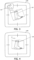
- Fig. 3 is a schematic diagram illustrating a first example of an anatomical structure 120 in an initial pose, ⁇ 1 , with respect to a projection X-ray imaging system 130b, in accordance with some aspects of the present disclosure.
- the pose is defined by the parameter ⁇ .
- the parameter ⁇ represents an angle between the Tibia within the ankle, i.e. the anatomical structure 120, and a vertical orientation of the X-ray detector 130b.
- Fig. 4 is a schematic diagram illustrating a first example of an anatomical structure 120 in a target pose, ⁇ T , with respect the projection X-ray imaging system 130b, in accordance with some aspects of the present disclosure.
- Fig. 4 has several features in common with Fig. 3 .
- Features in Fig. 4 that share the same labels as Fig. 3 refer to the same feature, and a description of the feature is not duplicated for the sake of brevity.
- the pose of the anatomical structure 120 illustrated in Fig. 4 has been adjusted by tilting the Tibia so as to reduce the parameter ⁇ from the initial value ⁇ 1 to the target value ⁇ T .
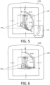
- FIG. 4 is a schematic diagram illustrating a second example of an anatomical structure 120 in an initial pose, ⁇ 1 , with respect to a projection X-ray imaging system 130b, in accordance with some aspects of the present disclosure.
- the pose is defined by the parameter ⁇ .
- the parameter ⁇ represents an angle of a line connecting the base of the Calcaneus, i.e. heel bone, and the first Metatarsal, with respect to a vertical orientation of the X-ray detector 130b.
- Fig. 6 is a schematic diagram illustrating a second example of an anatomical structure 120 in a target pose, ⁇ T , with respect to a projection X-ray imaging system 130b, in accordance with some aspects of the present disclosure.
- Fig. 6 has several features in common with Fig. 5 .
- Features in Fig. 6 that share the same labels as Fig. 5 refer to the same feature and a description of the feature is not duplicated for the sake of brevity.
- the pose of the anatomical structure 120 illustrated in Fig. 6 has been adjusted by reducing the parameter ⁇ from the initial value ⁇ 1 to the target value ⁇ T . Consequently, the anatomical structure 120 illustrated in Fig. 6 has the target pose with respect to the projection X-ray imaging system 130b.
- a combination of the parameters ⁇ , and ⁇ described above may also be used to define the pose of the anatomical structure 120 with respect to the projection X-ray imaging system.
- the parameters ⁇ , and ⁇ , described above may both be used to define the pose of the anatomical structure 120 with respect to the projection X-ray imaging system.
- the parameters ⁇ , and ⁇ also define a mutual positioning of anatomical features 150 1 , 150 2 , of the anatomical structure 120.
- ⁇ , and ⁇ define a mutual positioning of the Tibia 150 1 , and a line connecting the base of the Calcaneus, i.e. heel bone, and the first Metatarsal 150 2 .
- the pose of the anatomical structure 120 illustrated in Fig. 6 represents an adjustment to a mutual positioning ⁇ of the anatomical features 150 1 and 150 2 .
- the angle ⁇ represents an amount of flexion between the anatomical features 150 1 , and 150 2 .
- a rotation of the Tibia may be defined by a rotational angle that is measured around a vertical axis that is parallel to the surface of the X-ray detector 130b.
- a position of the medial process of the Talus may be defined by a vertical and a horizontal distance from the centre of the X-ray detector 130b.
- Such parameters may be used in addition to, or instead of, the example parameters ⁇ , and ⁇ , described above, to define a pose of the ankle 120 with respect to the projection X-ray imaging system.
- the image data i.e. the initial X-ray projection image representing the anatomical structure 120 and/or the camera image representing the anatomical structure 120
- the neural network In the operation S130, and in response to the inputting, the neural network generates pose adjustment information 110 for adjusting the initial pose ⁇ 1 , ⁇ 1 of the anatomical structure 120 with respect to the projection X-ray imaging system 130a, 130b in order to acquire the target X-ray projection image.
- the pose adjustment information 110 may be defined with respect to various datum.
- the pose adjustment information 110 may be defined with respect to the initial pose ⁇ 1 .
- the pose adjustment information 110 may be defined with respect to an orientation of a central axis 160 of the projection X-ray imaging system 130a, 130b.
- the pose adjustment information 110 may be defined with respect to an anatomy-specific coordinate system, e.g. the cranial-caudal axis, of the ventral-dorsal axis, or the medial-lateral axis, and so forth.
- Defining the pose adjustment information 110 with respect to the initial pose ⁇ 1 , or with respect to an anatomy-specific coordinate system facilitates ease of adjusting the pose of the anatomical structure 120, and also ease of annotating the images in the training data that is used to train the neural network.
- the neural network in this operation, the neural network generates pose adjustment information 110 in the form of a change in the parameter ⁇ , i.e.
- the anatomical structure 120 includes a plurality of anatomical features 150 1 , 2
- the pose adjustment information 110 represents an adjustment to a mutual positioning ⁇ of the anatomical features 150 1 , 2 .
- the pose adjustment information may include an adjustment to the angle ⁇ , or the angle ⁇ , and which consequently results in an adjustment to the angle ⁇ , and which represents a mutual positioning of the anatomical features 150 1 and 150 2 .
- Examples of other anatomical features, the positions of which may be adjusted in accordance with this example, in include bones, processes of bones, a shaft of a bone, gaps between bones, and so forth.
- the pose adjustment information 110 comprises an adjustment to an absolute position and/or an absolute orientation of the anatomical structure 120.
- the anatomical structure is adjusted rather than the projection X-ray imaging system.
- the projection X-ray imaging system remains static, and consequently the desired image may be acquired in a more efficient manner, thereby improving workflow.
- the neural network is trained to generate the pose adjustment information 110 using training data comprising a plurality of training images representing the anatomical structure 120, the training images respectively comprising X-ray projection images acquired with the anatomical structure in a current pose with respect the projection X-ray imaging system and/or camera images acquired by a camera configured to view the anatomical structure with the anatomical structure in the current pose with respect the projection X-ray imaging system, and wherein the training data further comprises, for each training image, corresponding pose adjustment information for adjusting the current pose of the anatomical structure with respect to the projection X-ray imaging system in order to acquire the target X-ray projection image.
- the neural network may be provided by various types of architectures, including for example a convolutional neural network “CNN” architecture, or a transformer, or a recurrent neural network “RNN” architecture with unidirectional or bidirectional long short-term memory “LSTM” architecture, etc.
- CNN convolutional neural network
- RNN recurrent neural network
- LSTM long short-term memory
- the training of a neural network involves inputting a training dataset into the neural network, and iteratively adjusting the neural network's parameters until the trained neural network provides an accurate output.
- Training is often performed using a Graphics Processing Unit “GPU” or a dedicated neural processor such as a Neural Processing Unit “NPU” or a Tensor Processing Unit “TPU”.
- Training often employs a centralized approach wherein cloud-based or mainframe-based neural processors are used to train a neural network.
- the trained neural network may be deployed to a device for analyzing new input data during inference.
- the processing requirements during inference are significantly less than those required during training, allowing the neural network to be deployed to a variety of systems such as laptop computers, tablets, mobile phones and so forth.
- Inference may for example be performed by a Central Processing Unit "CPU”, a GPU, an NPU, a TPU, on a server, or in the cloud.
- the process of training the neural network described above therefore includes adjusting its parameters.
- the training process automatically adjusts the weights and the biases, such that when presented with the input data, the neural network accurately provides the corresponding expected output data.
- the value of the loss functions, or errors are computed based on a difference between predicted output data and the expected output data.
- the value of the loss function may be computed using functions such as the negative log-likelihood loss, the mean absolute error (or L1 norm), the mean squared error, the root mean squared error (or L2 norm), the Huber loss, or the (binary) cross entropy loss.
- loss functions like the Kullback-Leibler divergence may additionally be used when training a variational autoencoder to ensure that the distribution of latent space encodings generated from temporal sequences of training X-ray images is similar to a standard Gaussian distribution with mean 0 and standard deviation of 1.
- the value of the loss function is typically minimized, and training is terminated when the value of the loss function satisfies a stopping criterion.
- training is terminated when the value of the loss function satisfies one or more of multiple criteria.
- the neural network may be trained to generate the pose adjustment information 110 by:
- the training data used in the training method described above may be acquired from historic imaging procedures.
- the training data may be acquired using an arrangement similar to that illustrated in Fig. 1 and Fig. 2 , and wherein the projection X-ray imaging system 130a, 130b is used to acquire for each imaging procedure an X-ray projection image representing the anatomical structure and/or the camera 140, which is configured to view the anatomical structure 120, is used to acquire a camera image representing the anatomical structure 120.
- the training images include camera images
- a pose of the camera with respect to the projection X-ray imaging system may be the same for the camera used to acquire the camera images and the camera used to acquire the camera images at inference.
- Each of the training images may be said to capture the anatomical structure with a current pose with respect to the projection X-ray imaging system.
- the training images are labelled, e.g. by an expert, with pose adjustment information 110 for adjusting the current pose of the anatomical structure with respect to the projection X-ray imaging system in order to acquire the target X-ray projection image.
- the training images may be labelled with pose adjustment information that includes adjustments ⁇ , and ⁇ to the parameters ⁇ , and ⁇ , described above with reference to Fig. 2 - Fig. 6 .
- the training images may be labelled with other pose adjustment information such as adjustments to a position of the anatomical structure, and so forth.
- Some tens, or hundreds, or thousands of training images from historic imaging procedures may be used to train the neural network.
- the training images may represent subjects having different ages, gender, body mass index, and so forth.
- the training images may include a variety of different pose adjustment information.
- Some of the training images may represent the anatomical structure in the target pose and are therefore labelled with pose adjustment information indicating that no pose adjustment is required in order to acquire the target X-ray projection image.
- the pose adjustment information 110 is outputted.
- the pose adjustment information that is outputted 110 may include an identification of the pose parameter(s) to be adjusted and a magnitude of the adjustment that is required in order to obtain the target pose.
- the pose adjustment information 110 may be outputted in any human-comprehensible manner, including graphically, and audially, for example.
- the pose adjustment information 110 may also be outputted in various ways, such as using a projector, or on a display. For instance, the operation of outputting S140 the pose adjustment information 110 may include projecting a graphical representation of the pose adjustment information 110.
- a graphical representation of the pose adjustment information 110 may be outputted onto the anatomical structure, or onto a portion of the projection X-ray imaging system, or onto a wall, for example.
- the operation of outputting S140 the pose adjustment information 110 may alternatively include outputting the received initial X-ray projection image representing the anatomical structure 120, and outputting the pose adjustment information 110 as an overlay on the image. In this case, the image, and the overlay, may be outputted to a display such as a monitor.
- the operation of outputting S140 the pose adjustment information 110 may alternatively include outputting the received camera image representing the anatomical structure 120, and outputting the pose adjustment information 110 as an overlay on the image. In this case, the image, and the overlay, may again be outputted to a display such as a monitor.
- a graphical representation of the pose adjustment information 110 is projected onto the X-ray detector 130b of the projection X-ray imaging system, and the pose adjustment information 110 includes a textual indication of the parameter to be adjusted, i.e. ⁇ and ⁇ , a numerical indication of the magnitude of the adjustment, and an icon indicating the direction of the adjustment that is required in order to obtain the target pose ⁇ T , and ⁇ T . More generally, the pose adjustment information 110 may be outputted in a numerical format or in a graphical format.
- the pose adjustment information 110 may be used to adjust the pose of the anatomical structure 120, and the target X-ray projection image may be acquired.
- the received image data comprises an X-ray projection image and/or a camera image acquired with the anatomical structure 120 in a target pose ⁇ T , ⁇ T with respect the projection X-ray imaging system 130a, 130b.
- the method described with reference to the flowchart illustrated in Fig. 7 includes:
- the training of the neural network is updated using additional training data that is acquired during inference. Consequently, over time, the neural network learns to generate the pose adjustment information from an increasingly large set of training data.
- This approach facilitates the deployment of the neural network following its training with a minimal set of training data, following which the accuracy of the pose adjustment information is improved over time due to the inclusion of the additional training data.
- the inherent variability within the newly-acquired training data facilitates the tailoring of the pose adjustment information to the preferences of the operator over time.
- the recording of the received image data may be performed based on user acceptance of the received image data as the additional training data. For instance, in this example, a prompt may be presented to a user via a display proposing the image for use as additional training data. If the operator considers the initial pose image suitable for acquiring a target X-ray projection image, the user may confirm the proposal, subsequent to which, further training of the neural network is performed. Groups of images may be recorded in this manner over time, subsequent to which the further training is performed with the group of images.
- the training data that is used to train the neural network includes, for each training image, context information indicating a context of the training image.
- the neural network is trained to generate the pose adjustment information 110 based further on the context information, and the method described with reference to the flowchart illustrated in Fig. 7 includes:
- An example of the context information that may be used in this example is a mobility constraint of the anatomical structure.
- the mobility constraint may indicate that one or more anatomical features in the anatomical structure are not mutually mobile, for instance.
- the corresponding pose adjustment information for such training images takes into account the mobility constraint.
- the corresponding pose adjustment information may be limited to global adjustments of the pose of the anatomical structure that do not alter the mutual positioning of anatomical features within the anatomical structure.
- the pose adjustment information 110 is generated by the neural network based on the mobility constraint, avoiding that un-obtainable poses of the anatomical structure are generated by the neural network.
- context information examples include an indication of the rationale for acquiring the X-ray projection image, or an indication of a diagnosis of the subject, or an indication of subject data such as age, body mass index, and so forth.
- Such context information may also place constraints on the ability to adjust the pose of an anatomical structure at-will. For instance, a subject that has had a fall may have one set of constraints on their mobility, and a subject over a specified age may have another set of constraints on their mobility. Consequently, by generating the pose adjustment information 110 based on such context information, it may be avoided that un-obtainable poses of the anatomical structure are generated by the neural network.
- a computer program product comprises instructions which when executed by one or more processors 210, cause the one or more processors to carry out a method of providing pose adjustment information 110 for adjusting a pose of an anatomical structure 120 with respect to a projection X-ray imaging system 130a, 130b in order to acquire a target X-ray projection image representing the anatomical structure 120.
- the method comprises:
- a system 100 for providing pose adjustment information 110 for adjusting a pose of an anatomical structure 120 with respect to a projection X-ray imaging system 130a, 130b in order to acquire a target X-ray projection image representing the anatomical structure 120 is provided.
- the system includes one or more processors 210 configured to:
- the system 100 may also include one or more of: a projection X-ray imaging system 130a, 130b for acquiring X-ray projection images; a camera 140 for acquiring camera images; a display (not illustrated in Fig. 1 for displaying the acquired images, the pose adjustment information 110, and so forth; and a user input device (not illustrated in Fig. 1 configured to receive user input fur use in relation to the method described above, such as a keyboard, a mouse, a touchscreen, and so forth.
- a projection X-ray imaging system 130a, 130b for acquiring X-ray projection images
- a camera 140 for acquiring camera images
- a display not illustrated in Fig. 1 for displaying the acquired images, the pose adjustment information 110, and so forth
- a user input device not illustrated in Fig. 1 configured to receive user input fur use in relation to the method described above, such as a keyboard, a mouse, a touchscreen, and so forth.
- the one or more processors 210 of the system 100 described above with reference to Fig. 1 and in Fig. 2 are configured to perform another method of providing pose adjustment information.
- a computer-implemented method of providing pose adjustment information 310 for adjusting a pose ⁇ 2 , ⁇ 2 of an anatomical structure 120 with respect to a projection X-ray imaging system 130a, 130b in order to acquire a target X-ray projection image 310 T representing the anatomical structure 120 is provided.
- the method includes:
- This method provides pose adjustment information that may be used to adjust an initial pose of an anatomical structure with respect to the projection X-ray imaging system in order to acquire a target X-ray projection image representing the anatomical structure, or in other words, a desired image.
- An initial X-ray projection image, and an initial camera image are acquired with the anatomical structure in the initial pose.
- the initial X-ray projection image may deviate from the target X-ray projection image.
- Pose adjustment information is then generated to determine how the anatomical structure in the initial X-ray projection image should be adjusted in order to acquire the target X-ray projection image. This operation may be performed using a neural network, as described in the aforementioned aspect.
- the registration operation and the deformation operation are then used in combination with the pose adjustment information to provide a target camera image, i.e. an image showing how the anatomical structure should have appeared if the target X-ray projection image had been acquired.
- a subsequent camera image is acquired with the anatomical structure in a subsequent pose.
- a deviation between the subsequent camera image and the target camera image is used to provide pose adjustment information for acquiring the target X-ray projection image. Since, in this method, the pose adjustment information is generated using the deviation between the subsequent camera image and the target camera image, the target X-ray projection image is acquired by positioning the anatomical structure without the need to acquire a subsequent X-ray projection image. This has the advantage of providing the target X-ray projection image with reduced X-ray dose to the subject.
- FIG. 8 is a flowchart illustrating an example of a method of providing pose adjustment information for adjusting a pose of an anatomical structure with respect to a projection X-ray imaging system in order to acquire a target X-ray projection image representing the anatomical structure, in accordance with some aspects of the present disclosure.
- image data is received.
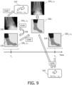
- the image data that is received in the operation S110 includes an initial X-ray projection image 310 1 representing the anatomical structure 120, an initial camera image 320 1 representing the anatomical structure 120, and a subsequent camera image 320 2 representing the anatomical structure 120. Examples of these images are illustrated in Fig. 9 , which is a schematic diagram illustrating an example of a method of providing pose adjustment information 310 for adjusting a pose ⁇ 2 of an anatomical structure 120 with respect to a projection X-ray imaging system in order to acquire a target X-ray projection image 310 T representing the anatomical structure 120, in accordance with some aspects of the present disclosure.
- the initial X-ray projection image 310 1 is acquired by the projection X-ray imaging system 130a, 130b with the anatomical structure 120 in an initial pose ⁇ 1 , ⁇ 1 with respect the projection X-ray imaging system 130a, 130b.
- the initial camera image 320 1 is acquired by a camera 140 configured to view the anatomical structure 120.
- the initial camera image is acquired with the anatomical structure 120 in the initial pose ⁇ 1 , ⁇ 1 with respect the projection X-ray imaging system 130a, 130b.
- the initial X-ray projection image 310 1 and the initial camera image 320 1 may be acquired concurrently, and at a first point in time, T 1 , as illustrated in the timeline in Fig. 9 .
- the subsequent camera image 320 2 is acquired by a camera 140 configured to view the anatomical structure 120.
- the subsequent camera image 320 2 is acquired with the anatomical structure 120 in a subsequent pose ⁇ 2 , ⁇ 2 with respect the projection X-ray imaging system 130a, 130b and at a later point in time T 2 to the initial camera image 320 1 .
- An example of the subsequent camera image 320 2 is illustrated on the right-hand side of Fig. 9 and at the time T 2 on the timeline.
- the camera images may be optical camera images acquired by an optical camera and/or depth camera images acquired by a depth camera.
- the camera 140 may also view at least a portion of the projection X-ray imaging system.
- the camera 140 may also view at least a portion of the X-ray source 130a, or at least a portion of the X-ray detector 130b.
- the camera 140 may acquire camera images representing the anatomical structure and at least a portion of the projection X-ray imaging system 130a, 130b.
- the initial X-ray projection image 310 1 and also the initial camera image 320 1 , are acquired with the anatomical structure 120 in an initial pose ⁇ 1 , ⁇ 1 with respect the projection X-ray imaging system 130a, 130b. Examples of the initial pose are described above with reference to Fig. 3 and Fig. 5 .
- the subsequent camera image 320 2 is acquired at a later point in time, Tz. There may be a time delay of some seconds, minutes, hours, days, or longer between the first point in time T 1 at which the anatomical structure 120 in the initial pose ⁇ 1 , ⁇ 1 , and the second point in time at which the anatomical structure 120 is in the subsequent pose ⁇ 2 , ⁇ 2 .
- the subsequent pose ⁇ 2 , ⁇ 2 of the anatomical structure 120 in the subsequent camera image 320 2 may differ from the initial pose ⁇ 1 , ⁇ 1 . This is illustrated by way of the different poses in the camera images 320 1 and 320 2 .
- the initial X-ray projection image 310 1 may be received from the projection X-ray imaging system 130a, 130b illustrated in Fig. 1
- the initial and subsequent camera images 320 1 and 320 2 may be received from the camera 140 illustrated in Fig. 1 .
- the image data may be received via any form of data communication, including wired, optical, and wireless communication.
- wired or optical communication the communication may take place via signals transmitted on an electrical or optical cable, and when wireless communication is used, the communication may for example be via RF or optical signals.
- pose adjustment information 110 is determined for adjusting the initial pose ⁇ 1 , ⁇ 1 of the anatomical structure 120 with respect to the projection X-ray imaging system 130a, 130b in order to acquire the target X-ray projection image 310 T representing the anatomical structure 120.
- This operation is illustrated in the top-left portion of Fig. 9 .
- the pose adjustment information 110 is determined based on the initial X-ray projection image 310 1 .
- the pose adjustment information determines how the anatomical structure in the initial X-ray projection image should be adjusted in order to acquire the target X-ray projection image 310 T .
- the operation S320 may be performed using a neural network, as described in the aforementioned aspect.
- the operation S320 may be performed using the neural network described above with reference to the operations S120, S130, and S140.
- the operation of determining S320 pose adjustment information 110 for adjusting the initial pose ⁇ 1 , ⁇ 1 of the anatomical structure 120 with respect to the projection X-ray imaging system 130a, 130b may include:
- the operation S320 may be performed based further on the initial camera image 320 1 representing the anatomical structure 120, as also described above in the operations S120, S130, and S140.
- the pose adjustment information may be determined in accordance with a technique disclosed in a document by Krönke, S., et al., "CNN-based pose estimation for assessing quality of ankle-joint X-ray images," Proc. SPIE 12032, Medical Imaging 2022: Image Processing, 120321A, 4 April 2022 .
- a registration 330 between the anatomical structure 120 in the initial X-ray projection image 310 1 and the anatomical structure 120 in the initial camera image 320 1 is determined.
- the registration operation S330 provides a mapping between the features in the initial X-ray projection image 310 1 and the corresponding features in the initial camera image 320 1 .
- the registration operation S330 may be performed by fitting a template kinematic model representing the anatomical structure 120 to the initial X-ray projection image 310 1 and the initial camera image 320 1 .
- a template kinematic model representing bone and tissue may be fitted to the initial X-ray projection image 310 1 by scaling the dimensions of features in the kinematic model and adjusting their poses.
- the registration 330 may a deformable registration, or an affine registration, for example.
- the anatomical structure 120 comprises one or more bones and tissue surrounding the one or more bones, and the operation S330 of determining a registration 330 between the anatomical structure 120 in the initial X-ray projection image 310 1 and the anatomical structure 120 in the initial camera image 320 1 , is performed using a kinematic model representing the bones and the tissue.
- the initial camera image 320 1 is deformed using the registration 330 and the pose adjustment information 110 to provide a target camera image 320 T corresponding to the target X-ray projection image 310 T .
- the resulting target camera image 320 T therefore indicates how the anatomical structure should appear in order to acquire the target X-ray projection image 310 T .
- the deforming operation S340 may be performed using known image processing techniques.
- the deforming operation may include performing a rigid, or a non-rigid, or an elastic deformation of the initial camera image 320 1 . This results in a target camera image 320 T corresponding to the target X-ray projection image 310 T , as illustrated in the central portion of Fig. 9 .
- pose adjustment information 310 is determined, based on a deviation between the subsequent camera image 320 2 and the target camera image 320 T .
- the pose adjustment information 310 is suitable for adjusting the subsequent pose ⁇ 2 , ⁇ 2 of the anatomical structure 120 with respect to the projection X-ray imaging system 130a, 130b in order to acquire the target X-ray projection image 310 T representing the anatomical structure 120.
- This operation is illustrated in the lower right-hand portion of Fig. 9 .
- the pose adjustment information 310 is determined based on a deviation between the subsequent camera image 320 2 and the target camera image 320 T .
- the operation S350 may be performed using various techniques, including using a trained model, or a statistical model.
- a trained model may be trained in a similar manner to the neural network described above with reference to the operations S120, S130, and S140.
- the trained model may be trained to generate the pose adjustment information using training data that includes training camera images representing the anatomical structure, and corresponding pose adjustment information that is provided by expert annotations.
- the operation S350 may be performed using a statistical model.
- the pose adjustment information 310 that is provided by the operation S350 facilitates adjustments to be made to the subsequent pose ⁇ 2 , ⁇ 2 without the need to acquire an X-ray projection image with the anatomical structure in the subsequent pose ⁇ 2 , ⁇ 2 . Consequently, the anatomical structure may be adjusted to provide a pose that is suitable for acquiring the target X-ray projection image 310 T with reduced X-ray dose to the subject.
- the pose adjustment information 310 is outputted.
- the pose adjustment information 310 may be outputted in a similar manner to that described above with reference to Fig. 3 , and Fig. 5 .
- the pose adjustment information 110 may be outputted in any human-comprehensible manner, including graphically, and audially, for example.
- the operation of outputting S360 the pose adjustment information 310 may include:
- the pose adjustment information 110 may be outputted in a numerical format or in a graphical format.
- the pose adjustment information 310 may be used to adjust the pose of the anatomical structure 120, and the target X-ray projection image 310 T may be acquired.
- the operation of receiving a subsequent camera image 320 2 representing the anatomical structure 120 is performed iteratively. In this example, the following operations are performed in each iteration:
- the iterative pose adjustment information that is provided in this example facilitates the repeated re-positioning of the anatomical structure until a target pose ⁇ T , ⁇ T is reached for acquiring the target X-ray projection image 310 T .
- the iterations may be performed substantially in real-time. This facilitates the live re-positioning of the anatomical structure and facilitates adjustments to the pose to be made that compensate for patient motion in the time interval between the acquisition of the subsequent camera image 320 2 and the acquisition of the target X-ray projection image 310 T .
- the pose adjustment information 310 for adjusting the initial pose ⁇ 1 , ⁇ 1 of the anatomical structure 120 with respect to the projection X-ray imaging system 130a, 130b in order to acquire the target X-ray projection image 310 T representing the anatomical structure 120 comprises an adjustment to an absolute position and/or an absolute orientation of the anatomical structure 120.
- the anatomical structure is adjusted rather than the projection X-ray imaging system.
- the projection X-ray imaging system remains static, and consequently the desired image may be acquired in a more efficient manner, thereby improving workflow.
- the anatomical structure 120 includes a plurality of anatomical features 150 1 , 150 2 , and the pose adjustment information 310 for adjusting the initial pose ⁇ 1 , ⁇ 1 of the anatomical structure 120 with respect to the projection X-ray imaging system 130a, 130b represents an adjustment to a mutual positioning ⁇ of the anatomical features.
- Examples of other anatomical features, the positions of which may be adjusted in accordance with this example, in include bones, processes of bones, a shaft of a bone, gaps between bones, and so forth.
- the pose adjustment information 310 is defined with respect to the initial pose ⁇ 1 , ⁇ 1 , or wherein the pose adjustment information 310 is defined with respect to an orientation of a central axis 160 of the projection X-ray imaging system 130a, 130b.
- the pose adjustment information 110 may be defined with respect to an anatomy-specific coordinate system, e.g. the cranial-caudal axis, of the ventral-dorsal axis, or the medial-lateral axis, and so forth. Defining the pose adjustment information 110 with respect to the initial pose ⁇ 1 , or with respect to an anatomy-specific coordinate system facilitates ease of annotating the images in the training data.
- the initial X-ray projection image 310 1 comprises a relatively lower X-ray dose than the target X-ray projection image 310 T .
- Such an initial X-ray projection image 310 1 may be referred-to as a "scout scan". This example has the advantage of reducing the total amount of X-ray dose to the subject.
- a computer program product comprises instructions which when executed by one or more processors 210, cause the one or more processors 210 to carry out a method of providing pose adjustment information 310 for adjusting a pose ⁇ 2 , ⁇ 2 of an anatomical structure 120 with respect to a projection X-ray imaging system 130a, 130b in order to acquire a target X-ray projection image 310 T representing the anatomical structure 120, the method comprising:
- a system 100 for providing pose adjustment information 310 for adjusting a pose ⁇ 2 , ⁇ 2 of an anatomical structure 120 with respect to a projection X-ray imaging system 130a, 130b in order to acquire a target X-ray projection image 310 T representing the anatomical structure 120 is provided.
- the system 100 comprises one or more processors 210 configured to:
- the system 100 may also include one or more of: a projection X-ray imaging system 130a, 130b for acquiring X-ray projection images; a camera 140 for acquiring camera images; a display (not illustrated in Fig. 1 for displaying the acquired images, the pose adjustment information 110, and so forth; and a user input device (not illustrated in Fig. 1 configured to receive user input fur use in relation to the method described above, such as a keyboard, a mouse, a touchscreen, and so forth.
- a projection X-ray imaging system 130a, 130b for acquiring X-ray projection images
- a camera 140 for acquiring camera images
- a display not illustrated in Fig. 1 for displaying the acquired images, the pose adjustment information 110, and so forth
- a user input device not illustrated in Fig. 1 configured to receive user input fur use in relation to the method described above, such as a keyboard, a mouse, a touchscreen, and so forth.
Landscapes
- Engineering & Computer Science (AREA)
- Health & Medical Sciences (AREA)
- Physics & Mathematics (AREA)
- Life Sciences & Earth Sciences (AREA)
- Theoretical Computer Science (AREA)
- General Health & Medical Sciences (AREA)
- Biomedical Technology (AREA)
- Biophysics (AREA)
- Molecular Biology (AREA)
- General Physics & Mathematics (AREA)
- Software Systems (AREA)
- Medical Informatics (AREA)
- Computing Systems (AREA)
- General Engineering & Computer Science (AREA)
- Data Mining & Analysis (AREA)
- Mathematical Physics (AREA)
- Computational Linguistics (AREA)
- Artificial Intelligence (AREA)
- Evolutionary Computation (AREA)
- Pathology (AREA)
- Surgery (AREA)
- Veterinary Medicine (AREA)
- High Energy & Nuclear Physics (AREA)
- Public Health (AREA)
- Nuclear Medicine, Radiotherapy & Molecular Imaging (AREA)
- Optics & Photonics (AREA)
- Animal Behavior & Ethology (AREA)
- Radiology & Medical Imaging (AREA)
- Heart & Thoracic Surgery (AREA)
- Orthopedic Medicine & Surgery (AREA)
- Computer Vision & Pattern Recognition (AREA)
- Dentistry (AREA)
- Oral & Maxillofacial Surgery (AREA)
- Apparatus For Radiation Diagnosis (AREA)
Priority Applications (7)
| Application Number | Priority Date | Filing Date | Title |
|---|---|---|---|
| EP23159085.2A EP4424239A1 (de) | 2023-02-28 | 2023-02-28 | Bereitstellung von poseneinstellungsinformationen |
| EP24705187.3A EP4673054A1 (de) | 2023-02-28 | 2024-02-19 | Bereitstellung von poseneinstellungsinformationen |
| CN202480015466.0A CN120826190A (zh) | 2023-02-28 | 2024-02-19 | 提供姿势调节信息 |
| PCT/EP2024/054146 WO2024179871A1 (en) | 2023-02-28 | 2024-02-19 | Providing pose adjustment information |
| CN202480015442.5A CN120826189A (zh) | 2023-02-28 | 2024-02-19 | 提供姿势调节信息 |
| PCT/EP2024/054139 WO2024179868A1 (en) | 2023-02-28 | 2024-02-19 | Providing pose adjustment information |
| EP24704515.6A EP4673053A1 (de) | 2023-02-28 | 2024-02-19 | Bereitstellung von poseneinstellungsinformationen |
Applications Claiming Priority (1)
| Application Number | Priority Date | Filing Date | Title |
|---|---|---|---|
| EP23159085.2A EP4424239A1 (de) | 2023-02-28 | 2023-02-28 | Bereitstellung von poseneinstellungsinformationen |
Publications (1)
| Publication Number | Publication Date |
|---|---|
| EP4424239A1 true EP4424239A1 (de) | 2024-09-04 |
Family
ID=85410340
Family Applications (3)
| Application Number | Title | Priority Date | Filing Date |
|---|---|---|---|
| EP23159085.2A Withdrawn EP4424239A1 (de) | 2023-02-28 | 2023-02-28 | Bereitstellung von poseneinstellungsinformationen |
| EP24705187.3A Pending EP4673054A1 (de) | 2023-02-28 | 2024-02-19 | Bereitstellung von poseneinstellungsinformationen |
| EP24704515.6A Pending EP4673053A1 (de) | 2023-02-28 | 2024-02-19 | Bereitstellung von poseneinstellungsinformationen |
Family Applications After (2)
| Application Number | Title | Priority Date | Filing Date |
|---|---|---|---|
| EP24705187.3A Pending EP4673054A1 (de) | 2023-02-28 | 2024-02-19 | Bereitstellung von poseneinstellungsinformationen |
| EP24704515.6A Pending EP4673053A1 (de) | 2023-02-28 | 2024-02-19 | Bereitstellung von poseneinstellungsinformationen |
Country Status (3)
| Country | Link |
|---|---|
| EP (3) | EP4424239A1 (de) |
| CN (2) | CN120826189A (de) |
| WO (2) | WO2024179871A1 (de) |
Families Citing this family (1)
| Publication number | Priority date | Publication date | Assignee | Title |
|---|---|---|---|---|
| CN119970067B (zh) * | 2025-01-15 | 2025-10-03 | 深圳市拓普智造科技有限公司 | 一种面向平片过程的摆位引导方法和系统、相关设备 |
Citations (5)
| Publication number | Priority date | Publication date | Assignee | Title |
|---|---|---|---|---|
| US20180247427A1 (en) * | 2017-02-24 | 2018-08-30 | Siemens Healthcare Gmbh | Patient Position Control for Scanning |
| WO2019134874A1 (en) | 2018-01-03 | 2019-07-11 | Koninklijke Philips N.V. | Field of view adjustment |
| US20190318497A1 (en) * | 2018-04-11 | 2019-10-17 | Siemens Healthcare Gmbh | System and method for assisted patient positioning |
| WO2020056086A1 (en) * | 2018-09-12 | 2020-03-19 | Orthogrid Systems, Inc. | An artificial intelligence intra-operative surgical guidance system and method of use |
| EP3936052A1 (de) * | 2020-07-07 | 2022-01-12 | Koninklijke Philips N.V. | Benutzerschnittstelle zur ausrichtung eines röntgenröhrendetektors |
Family Cites Families (3)
| Publication number | Priority date | Publication date | Assignee | Title |
|---|---|---|---|---|
| BR112017002906A2 (pt) * | 2015-05-20 | 2017-12-12 | Koninklijke Philips Nv | sistema de orientação, conjunto de imageamento médico, método para orientar o posicionamento de uma anatomia de interesse de um paciente, elemento de programa de computador, e, mídia legível por computador |
| DE102020213690B4 (de) * | 2020-10-30 | 2022-01-20 | Siemens Healthcare Gmbh | Verfahren zum Einstellen einer Form einer Kopfunterlage, Verfahren zum Bereitstellen von Bildgebungsdaten und System mit einer Kopfunterlage |
| WO2022099068A1 (en) * | 2020-11-06 | 2022-05-12 | Materialise Nv | System and methods for calibration of x-ray images |
-
2023
- 2023-02-28 EP EP23159085.2A patent/EP4424239A1/de not_active Withdrawn
-
2024
- 2024-02-19 CN CN202480015442.5A patent/CN120826189A/zh active Pending
- 2024-02-19 WO PCT/EP2024/054146 patent/WO2024179871A1/en not_active Ceased
- 2024-02-19 WO PCT/EP2024/054139 patent/WO2024179868A1/en not_active Ceased
- 2024-02-19 EP EP24705187.3A patent/EP4673054A1/de active Pending
- 2024-02-19 EP EP24704515.6A patent/EP4673053A1/de active Pending
- 2024-02-19 CN CN202480015466.0A patent/CN120826190A/zh active Pending
Patent Citations (5)
| Publication number | Priority date | Publication date | Assignee | Title |
|---|---|---|---|---|
| US20180247427A1 (en) * | 2017-02-24 | 2018-08-30 | Siemens Healthcare Gmbh | Patient Position Control for Scanning |
| WO2019134874A1 (en) | 2018-01-03 | 2019-07-11 | Koninklijke Philips N.V. | Field of view adjustment |
| US20190318497A1 (en) * | 2018-04-11 | 2019-10-17 | Siemens Healthcare Gmbh | System and method for assisted patient positioning |
| WO2020056086A1 (en) * | 2018-09-12 | 2020-03-19 | Orthogrid Systems, Inc. | An artificial intelligence intra-operative surgical guidance system and method of use |
| EP3936052A1 (de) * | 2020-07-07 | 2022-01-12 | Koninklijke Philips N.V. | Benutzerschnittstelle zur ausrichtung eines röntgenröhrendetektors |
Non-Patent Citations (1)
| Title |
|---|
| KRONKE, S. ET AL.: "CNN-based pose estimation for assessing quality of ankle-joint X-ray images", PROC. SPIE 12032, MEDICAL IMAGING 2022: IMAGE PROCESSING, 120321A, 4 April 2022 (2022-04-04) |
Also Published As
| Publication number | Publication date |
|---|---|
| CN120826190A (zh) | 2025-10-21 |
| EP4673053A1 (de) | 2026-01-07 |
| CN120826189A (zh) | 2025-10-21 |
| WO2024179868A1 (en) | 2024-09-06 |
| WO2024179871A1 (en) | 2024-09-06 |
| EP4673054A1 (de) | 2026-01-07 |
Similar Documents
| Publication | Publication Date | Title |
|---|---|---|
| EP4584750B1 (de) | Bereitstellung von poseinformationen für röntgenprojektionsbilder | |
| EP3586787B1 (de) | Bildabgleichsvorrichtung und bildabgleichsverfahren | |
| US9538940B2 (en) | Intelligent algorithms for tracking three-dimensional skeletal movement from radiographic image sequences | |
| CN112825619B (zh) | 使用数字重建放射影像训练机器学习算法的方法及系统 | |
| CN106999130B (zh) | 用于确定在投影图像中介入仪器的位置的装置 | |
| CN109937012A (zh) | 为成像系统选择采集参数 | |
| RU2762146C1 (ru) | Устройство для обработки медицинских изображений, способ обработки медицинских изображений и носитель данных | |
| US20170178340A1 (en) | Device, system and method for segmenting an image of a subject | |
| EP4395652B1 (de) | Objektvisualisierung in der röntgenbildgebung | |
| CN110459298B (zh) | 用于求出结果值的方法和设备、诊断站和成像系统 | |
| EP4424239A1 (de) | Bereitstellung von poseneinstellungsinformationen | |
| EP3370616B1 (de) | Vorrichtung zur abbildung eines objekts | |
| WO2022261528A1 (en) | Using machine learning and 3d projection to guide medical procedures | |
| CN108430376A (zh) | 提供投影数据集 | |
| CN118037784A (zh) | 用于基于机械获取的组织表面数据确定表面配准的技术 | |
| CN112204616B (zh) | 用于医学成像的自动化对象监测 | |
| EP4408292B1 (de) | Vorausschauende qualitätsbeurteilung für eine bildgebende untersuchung vor der erfassung | |
| EP4059435A1 (de) | Patientenpräparat zur medizinischen bildgebung | |
| KR102927080B1 (ko) | 3차원 뼈 모델을 재건하는 장치 및 방법 | |
| EP4586186A1 (de) | Unterstützung der beurteilung der bildqualität in medizinischen bildern | |
| US20230263494A1 (en) | Re-imaging determination support device, learning device, re-imaging support device, recording medium, and re-imaging determination support method | |
| CN115661234B (zh) | 图像间规划点同步装置、电子设备、存储介质及相关方法 | |
| JP2025539764A (ja) | 投影画像の提供 | |
| CN120543604A (zh) | 结构光影像配准方法、装置、设备、介质和程序产品 | |
| CN121358406A (zh) | 医学扫描规划装置 |
Legal Events
| Date | Code | Title | Description |
|---|---|---|---|
| PUAI | Public reference made under article 153(3) epc to a published international application that has entered the european phase |
Free format text: ORIGINAL CODE: 0009012 |
|
| STAA | Information on the status of an ep patent application or granted ep patent |
Free format text: STATUS: THE APPLICATION HAS BEEN PUBLISHED |
|
| AK | Designated contracting states |
Kind code of ref document: A1 Designated state(s): AL AT BE BG CH CY CZ DE DK EE ES FI FR GB GR HR HU IE IS IT LI LT LU LV MC ME MK MT NL NO PL PT RO RS SE SI SK SM TR |
|
| STAA | Information on the status of an ep patent application or granted ep patent |
Free format text: STATUS: THE APPLICATION IS DEEMED TO BE WITHDRAWN |
|
| 18D | Application deemed to be withdrawn |
Effective date: 20250305 |