EP4424225A1 - Dental handpiece - Google Patents
Dental handpiece Download PDFInfo
- Publication number
- EP4424225A1 EP4424225A1 EP22856988.5A EP22856988A EP4424225A1 EP 4424225 A1 EP4424225 A1 EP 4424225A1 EP 22856988 A EP22856988 A EP 22856988A EP 4424225 A1 EP4424225 A1 EP 4424225A1
- Authority
- EP
- European Patent Office
- Prior art keywords
- diffuser
- housing
- handle
- air jet
- shielding window
- Prior art date
- Legal status (The legal status is an assumption and is not a legal conclusion. Google has not performed a legal analysis and makes no representation as to the accuracy of the status listed.)
- Pending
Links
- 230000003287 optical effect Effects 0.000 claims abstract description 41
- 238000012800 visualization Methods 0.000 claims abstract description 7
- 239000003570 air Substances 0.000 description 84
- 239000002245 particle Substances 0.000 description 11
- 239000007788 liquid Substances 0.000 description 6
- 238000007664 blowing Methods 0.000 description 4
- 238000002360 preparation method Methods 0.000 description 4
- 239000007787 solid Substances 0.000 description 3
- XLYOFNOQVPJJNP-UHFFFAOYSA-N water Substances O XLYOFNOQVPJJNP-UHFFFAOYSA-N 0.000 description 3
- 230000000712 assembly Effects 0.000 description 2
- 238000000429 assembly Methods 0.000 description 2
- 238000011109 contamination Methods 0.000 description 2
- 238000005507 spraying Methods 0.000 description 2
- 239000012080 ambient air Substances 0.000 description 1
- 238000004140 cleaning Methods 0.000 description 1
- 150000001875 compounds Chemical class 0.000 description 1
- 210000003298 dental enamel Anatomy 0.000 description 1
- 210000004268 dentin Anatomy 0.000 description 1
- 230000000694 effects Effects 0.000 description 1
- 239000012634 fragment Substances 0.000 description 1
- 239000011521 glass Substances 0.000 description 1
- 238000000034 method Methods 0.000 description 1
- 230000000717 retained effect Effects 0.000 description 1
- 230000000007 visual effect Effects 0.000 description 1
Images

Classifications
-
- A—HUMAN NECESSITIES
- A61—MEDICAL OR VETERINARY SCIENCE; HYGIENE
- A61C—DENTISTRY; APPARATUS OR METHODS FOR ORAL OR DENTAL HYGIENE
- A61C9/00—Impression cups, i.e. impression trays; Impression methods
- A61C9/004—Means or methods for taking digitized impressions
- A61C9/0046—Data acquisition means or methods
- A61C9/0053—Optical means or methods, e.g. scanning the teeth by a laser or light beam
-
- A—HUMAN NECESSITIES
- A61—MEDICAL OR VETERINARY SCIENCE; HYGIENE
- A61B—DIAGNOSIS; SURGERY; IDENTIFICATION
- A61B1/00—Instruments for performing medical examinations of the interior of cavities or tubes of the body by visual or photographical inspection, e.g. endoscopes; Illuminating arrangements therefor
- A61B1/12—Instruments for performing medical examinations of the interior of cavities or tubes of the body by visual or photographical inspection, e.g. endoscopes; Illuminating arrangements therefor with cooling or rinsing arrangements
- A61B1/126—Instruments for performing medical examinations of the interior of cavities or tubes of the body by visual or photographical inspection, e.g. endoscopes; Illuminating arrangements therefor with cooling or rinsing arrangements provided with means for cleaning in-use
-
- A—HUMAN NECESSITIES
- A61—MEDICAL OR VETERINARY SCIENCE; HYGIENE
- A61B—DIAGNOSIS; SURGERY; IDENTIFICATION
- A61B1/00—Instruments for performing medical examinations of the interior of cavities or tubes of the body by visual or photographical inspection, e.g. endoscopes; Illuminating arrangements therefor
- A61B1/00064—Constructional details of the endoscope body
- A61B1/00071—Insertion part of the endoscope body
- A61B1/0008—Insertion part of the endoscope body characterised by distal tip features
- A61B1/00091—Nozzles
-
- A—HUMAN NECESSITIES
- A61—MEDICAL OR VETERINARY SCIENCE; HYGIENE
- A61B—DIAGNOSIS; SURGERY; IDENTIFICATION
- A61B1/00—Instruments for performing medical examinations of the interior of cavities or tubes of the body by visual or photographical inspection, e.g. endoscopes; Illuminating arrangements therefor
- A61B1/00163—Optical arrangements
- A61B1/00174—Optical arrangements characterised by the viewing angles
- A61B1/00179—Optical arrangements characterised by the viewing angles for off-axis viewing
-
- A—HUMAN NECESSITIES
- A61—MEDICAL OR VETERINARY SCIENCE; HYGIENE
- A61B—DIAGNOSIS; SURGERY; IDENTIFICATION
- A61B1/00—Instruments for performing medical examinations of the interior of cavities or tubes of the body by visual or photographical inspection, e.g. endoscopes; Illuminating arrangements therefor
- A61B1/06—Instruments for performing medical examinations of the interior of cavities or tubes of the body by visual or photographical inspection, e.g. endoscopes; Illuminating arrangements therefor with illuminating arrangements
- A61B1/0661—Endoscope light sources
- A61B1/0684—Endoscope light sources using light emitting diodes [LED]
-
- A—HUMAN NECESSITIES
- A61—MEDICAL OR VETERINARY SCIENCE; HYGIENE
- A61B—DIAGNOSIS; SURGERY; IDENTIFICATION
- A61B1/00—Instruments for performing medical examinations of the interior of cavities or tubes of the body by visual or photographical inspection, e.g. endoscopes; Illuminating arrangements therefor
- A61B1/24—Instruments for performing medical examinations of the interior of cavities or tubes of the body by visual or photographical inspection, e.g. endoscopes; Illuminating arrangements therefor for the mouth, i.e. stomatoscopes, e.g. with tongue depressors; Instruments for opening or keeping open the mouth
- A61B1/247—Instruments for performing medical examinations of the interior of cavities or tubes of the body by visual or photographical inspection, e.g. endoscopes; Illuminating arrangements therefor for the mouth, i.e. stomatoscopes, e.g. with tongue depressors; Instruments for opening or keeping open the mouth with means for viewing areas outside the direct line of sight, e.g. dentists' mirrors
- A61B1/253—Instruments for performing medical examinations of the interior of cavities or tubes of the body by visual or photographical inspection, e.g. endoscopes; Illuminating arrangements therefor for the mouth, i.e. stomatoscopes, e.g. with tongue depressors; Instruments for opening or keeping open the mouth with means for viewing areas outside the direct line of sight, e.g. dentists' mirrors with means for preventing fogging
-
- A—HUMAN NECESSITIES
- A61—MEDICAL OR VETERINARY SCIENCE; HYGIENE
- A61C—DENTISTRY; APPARATUS OR METHODS FOR ORAL OR DENTAL HYGIENE
- A61C1/00—Dental machines for boring or cutting ; General features of dental machines or apparatus, e.g. hand-piece design
- A61C1/02—Dental machines for boring or cutting ; General features of dental machines or apparatus, e.g. hand-piece design characterised by the drive of the dental tools
- A61C1/05—Dental machines for boring or cutting ; General features of dental machines or apparatus, e.g. hand-piece design characterised by the drive of the dental tools with turbine drive
- A61C1/052—Ducts for supplying driving or cooling fluid, e.g. air, water
-
- A—HUMAN NECESSITIES
- A61—MEDICAL OR VETERINARY SCIENCE; HYGIENE
- A61C—DENTISTRY; APPARATUS OR METHODS FOR ORAL OR DENTAL HYGIENE
- A61C1/00—Dental machines for boring or cutting ; General features of dental machines or apparatus, e.g. hand-piece design
- A61C1/08—Machine parts specially adapted for dentistry
- A61C1/088—Illuminating devices or attachments
-
- A—HUMAN NECESSITIES
- A61—MEDICAL OR VETERINARY SCIENCE; HYGIENE
- A61C—DENTISTRY; APPARATUS OR METHODS FOR ORAL OR DENTAL HYGIENE
- A61C1/00—Dental machines for boring or cutting ; General features of dental machines or apparatus, e.g. hand-piece design
- A61C1/08—Machine parts specially adapted for dentistry
- A61C1/14—Tool-holders, i.e. operating tool holders, e.g. burr holders
- A61C1/141—Tool-holders, i.e. operating tool holders, e.g. burr holders in an angled handpiece
-
- A—HUMAN NECESSITIES
- A61—MEDICAL OR VETERINARY SCIENCE; HYGIENE
- A61C—DENTISTRY; APPARATUS OR METHODS FOR ORAL OR DENTAL HYGIENE
- A61C17/00—Devices for cleaning, polishing, rinsing or drying teeth, teeth cavities or prostheses; Saliva removers; Dental appliances for receiving spittle
- A61C17/02—Rinsing or air-blowing devices, e.g. using fluid jets or comprising liquid medication
- A61C17/022—Air-blowing devices, e.g. with means for heating the air
Definitions
- the present invention relates to dentistry equipment, and more specifically to dental handpieces comprising a handle and a housing with an optical emission source represented by at least one light-emitting diode connected to an electric power supply, said handpiece having an optical sensor adapted to be connected to visualization devices, said handpiece can be used by dentists for dental treatment.
- a known example of prior art is a dental handpiece comprising a handle and a housing with an optical emission source represented by at least one light-emitting diode connected to an electric power supply, said handpiece having an optical sensor adapted to be connected to visualization devices, see description of the utility model RU114603 published in 2012.
- Said device is the closest art versus the claimed invention and is considered as a prototype.
- the claimed invention shall be described in terms of differences from the prototype.
- a drawback of said device is that it has a video camera (an optical sensor) which allows to project an image of the mouth cavity to an external screen but cannot ensure that no particles from the mouth cavity get on its surface during dental treatment.
- a video camera an optical sensor
- certain tools such as drills, can produce solid fragments flying at high speeds that are capable of crossing over an ambient air and getting on the video camera.
- the present invention mainly aims to offer a dental handpiece comprising a handle and a housing with an optical emission source represented by at least one light-emitting diode connected to an electric power supply, said dental handpiece having an optical sensor adapted to be connected to visualization devices, said dental handpiece being capable of ensuring reliable protection of the optical sensor by way of an air curtain, which is a stated technical problem.
- the diffuser is located from a working end of the housing and is designed so as to direct the air jet away from the housing end (in the direction of the handle).
- the optical sensor is located (along the handle) between the drill bit and the handle.
- the air jet is directed tangentially to the shielding window away from the working end of the housing, that is, under operational conditions, away from a patient's mouth to help an operator in handling the drill bit and to improve cleaning of the patient's mouth cavity.
- the diffuser is located from a working end of the housing and is designed so as to direct the air jet away from the handle.
- the housing has a protrusion located from the working end, said protrusion having a surface shape which turns the air jet to 120°-140°.
- the drill bit is located between the handle and the optical sensor.
- the air jet is directed tangentially onto the shielding window and away from the handle along the (end of the) housing, then gets rotated by the protrusion, that is, under operational conditions, away from a patient's mouth. This expands the functional capabilities of the dental handpiece and creates an additional convenience for the drill bit operator.
- the housing has the protrusion located from the working end, said protrusion having a surface shape which turns the air jet to 120°-140°, the formed jet consists of two echelons with differently directed flows.
- Such complex flow of the high-speed jets makes it possible to increase an efficiency of interception of flying particles by extending their range in velocities and densities. This additionally prevents contamination of the optics.
- the diffuser is located from a working end of the housing and is oriented perpendicularly to the handle. Said diffuser is designed so as to direct the air jet sideways from the handle.
- the housing has a protrusion located from the working end, said protrusion having a surface shape which turns the air jet to 120°-140°.
- the diffuser is designed so as to generate the air jet having an outflow speed ranging from 6 m/s to 50 m/s, said outflow speed forming an angle from 0° to 15° with a plane of the transparent shielding window.
- FIG. 1 to 14 indicate:
- a compressed air source (dental set compressor) is not shown in the figures.
- a dental handpiece comprises a handle 6 and a housing 18 with an optical emission source represented by at least one light-emitting diode 17 connected to an electric power supply. Said handpiece having an optical sensor 4 adapted to be connected to visualization devices, not shown in the figures.
- the housing 18 has a transparent shielding window 3 of the optical sensor.
- the handpiece has a device for supplying compressed air on the transparent shielding window, also shown as a compressed air supplying tube 11.
- the housing 18 has an aperture for supplying compressed air to the transparent shielding window connected to the device for supplying compressed air.
- a diffuser 16 is located in the aperture, said diffuser being designed so as to generate an air jet forming an air curtain before the transparent shielding window 3.
- the diffuser 16 is located from a working end of the housing 18 and is designed so as to direct the air jet away from the working end of the housing 18 towards the handle (that is, a diffuser outlet is directed to the handle): see figures 1 and 2 .
- the diffuser 16 is located from a working end of the housing 18 and is designed so as to direct the air jet away from the handle 6, that is, an outlet of the diffuser is directed away from the handle (along its length).
- the housing 18 comprises a protrusion located from the working end, said protrusion having a surface shape which turns the air jet to 120°-140°: see figures 3-4 , 9-10 .
- the diffuser 16 is located from the transparent shielding window 3 and oriented perpendicularly to the handle 6.
- the diffuser 16 is designed so as to direct the air jet sideways from the handle 6 of the housing 18, that is, an outlet of the diffuser 16 is directed sideways from the handle 6.
- the housing 18 comprises a protrusion located from the working end, said protrusion having a surface shape which turns the air jet to 120°-140°: see figures 5-6 , 9-10 .
- the diffuser 16 is also preferably designed so as to generate the air jet with the outflow speed ranging from 6 m/s to 50 m/s and forming an angle from 0° to 15° with a plane of the transparent shielding window 3.
- Said dental handpiece is also designed with several air supply options: direct (without turning the air curtain flow as shown in the figures 1 , 7 ) and reverse (with turning of the air curtain, as shown in the figures 3 , 5-6 , 8-10 ), and in different locations of the optical sensor 4 relative to a drill bit 12 (in front of, behind, to the right, to the left, relative to a longitudinal axis of the drill bit 12), as is evident from figures 1-6 .
- the dental handpiece operates as follows. Below is the most exhaustive example of the embodiment of the invention, however, said example does not limit other applications of the invention.
- a compressed air is supplied from a dental unit compressor through a compressed air supplying tube 11 as a channeled air jet to a housing 18.
- a compressed air supplying tube 11 as a channeled air jet to a housing 18.
- the air passes through the housing 18, it goes to a directional diffuser 16 that forms a flat jet directed at an angle from 1 to 15 degrees to the housing 18 surface with an outflow speed ranging from 6 m/s to 50 m/s.
- the high-speed jet does not allow foreign particles having densities and speeds typical for dental interventions pass through its core and moves them away from the transparent shielding window 3 of the optical sensor (camera) 4.
- Quantitative attributes of the technical parameters such as an the air jet turning angle, the air jet outflow speed and the angle between the air jet outflow and the transparent shielding window 3 plane in the range of continuously changing variables can be adjusted by varying a protrusion and the diffuser 16 geometry.
- Blowing efficiency control method shall be a visual control of readability of the image transferred from the optical sensor 4 and contaminated with artifacts due to foreign particles and liquid droplets getting onto the transparent shielding window 3.
- the number of image artifacts shall be assumed as a criterion of blowing efficiency in four tiers:
- Air jet rotation angle is adjusted in the range from 120° to 140° by adjusting the shape of the protrusion surface directed at the diffuser 16.
- a protrusion incline angle shall be the geometrical parameter for an airjet turning angle.
- the protrusion incline angle is found between the tangential line to the margin of the concave surface and the plane of the transparent shielding window 3.
- Air jet outflow was adjusted in the range from 6 m/s to 50 m/s by adjusting the diffuser 16 outlet cross-section area.
- the geometrical parameter characterizing air jet outflow speed was round section diameter with the same area as the diffuser 16 outlet cross-section. See Table 2 for the relationship between air jet outflow, image artifact grade, and the above geometrical parameter. Table 2. Dependence of air jet outflow speed and image artifact grade from equivalent round section diameter. No Air jet outflow speed, m/s Equivalent round section diameter, mm Image artifact grade 1 3 2,8 Severe 2 6 2,0 Medium 3 10 1,6 Moderate 4 20 1,1 Moderate 5 30 0,9 Moderate 6 40 0,8 None 7 50 0,7 None
- the angle between the air curtain outflow direction and shielding window plane was adjusted in the range from 0 to 15 degrees by adjusting the diffuser 16 outlet cross-section aperture angle.
- the diffuser 16 outlet cross-section aperture angle was assumed as the characteristic geometrical parameter. See Table 3 for the dependence of the angle between the direction of the air curtain outflow direction and shielding window plane and image artifact grade on the above geometrical parameter. Table 3. Dependence of the angle between the direction of the air curtain outflow direction and shielding window 3 plane and image artifact grade on the diffuser 16 outlet cross-section aperture angle.
- the invention relates to a dental handpiece comprising:
- the diffuser 16 is located from a working end of the housing 18.
- the diffuser 16 is designed so as to direct the air jet away from the working end of the housing 18 longitudinally towards the handle 6.
- the diffuser 16 is located from the working end of the housing 18. Under these conditions, the diffuser 16 is designed so as to direct the air jet away from the handle 6 (that is, along the length of the handle 6).
- the housing 18 has a protrusion located from the working end. The protrusion has a surface shape which turns the air jet outgoing from the diffuser 16 in a first range from 120° to 140° ( Figures 9 to 10 ).
- the diffuser 16 is located from the working end of the housing 18 and oriented perpendicularly to the handle 6.
- the diffuser 16 is designed so as to direct the air jet sideways from the housing 18 handle 6.
- the housing 18 comprises a protrusion located from the working end.
- the protrusion has a surface shape which turns the air jet outgoing from the diffuser 16 by the first angle in the first range from 120° to 140° ( Figures 9-10 ).
- the diffuser 16 is designed so as to generate the air jet with an outflow speed ranging from 6 m/s to 50 m/s ( Figures 11-12 ).
- This air jet outflow forms a second angle with a plane of the transparent shielding window 3, said second angle being comprised in a second range from 0° to 15° ( Figures 13 to 14 ).
- the claimed dental handpiece may be implemented by a person skilled in the art in practice and ensures that the claimed objectives are met after implementation, which leads to the conclusion that the invention meets the requirement of "industrial applicability".
- a series of real-life tests was performed to confirm the operability of the proposed dental handpiece.
- the preparation of the upper 8 th tooth with a compound cavity was recorded on the video.
- the preparation was made using a standard air turbine handpiece with standard water spraying of the intervention area.
- the sensor shielding window was located in the range from 25 mm to 28 mm from the preparation area at the angle of 60 to 70 degrees. No additional optics protection measures were taken, only standard-grade dental equipment and tools specific for such interventions were used.
- the video shows that, under the conditions of active water supplying and high-intensity spraying, the transparent shielding window 3 is not polluted by solid enamel and dentine particles cut by rotating tools, and that the camera 4 continues operation throughout the intervention.
- Said dental handpiece is also designed with several air feed options: direct and reverse (with turning of the air curtain flow) and in different locations of the optical sensor 4 relative to the drill bit 12 (in front of, behind, to the right, to the left, relative to the drill bit 12 longitudinal axis).
Landscapes
- Health & Medical Sciences (AREA)
- Life Sciences & Earth Sciences (AREA)
- Surgery (AREA)
- Veterinary Medicine (AREA)
- Public Health (AREA)
- General Health & Medical Sciences (AREA)
- Animal Behavior & Ethology (AREA)
- Physics & Mathematics (AREA)
- Optics & Photonics (AREA)
- Engineering & Computer Science (AREA)
- Biophysics (AREA)
- Radiology & Medical Imaging (AREA)
- Biomedical Technology (AREA)
- Heart & Thoracic Surgery (AREA)
- Medical Informatics (AREA)
- Molecular Biology (AREA)
- Pathology (AREA)
- Nuclear Medicine, Radiotherapy & Molecular Imaging (AREA)
- Oral & Maxillofacial Surgery (AREA)
- Dentistry (AREA)
- Epidemiology (AREA)
- Microelectronics & Electronic Packaging (AREA)
- Dental Tools And Instruments Or Auxiliary Dental Instruments (AREA)
Abstract
Description
- The present invention relates to dentistry equipment, and more specifically to dental handpieces comprising a handle and a housing with an optical emission source represented by at least one light-emitting diode connected to an electric power supply, said handpiece having an optical sensor adapted to be connected to visualization devices, said handpiece can be used by dentists for dental treatment.
- A known example of prior art is a dental handpiece comprising a handle and a housing with an optical emission source represented by at least one light-emitting diode connected to an electric power supply, said handpiece having an optical sensor adapted to be connected to visualization devices, see description of the utility model RU114603 published in 2012.
- Said device is the closest art versus the claimed invention and is considered as a prototype. Thus, the claimed invention shall be described in terms of differences from the prototype.
- A drawback of said device is that it has a video camera (an optical sensor) which allows to project an image of the mouth cavity to an external screen but cannot ensure that no particles from the mouth cavity get on its surface during dental treatment. Indeed, certain tools, such as drills, can produce solid fragments flying at high speeds that are capable of crossing over an ambient air and getting on the video camera.
- The present invention mainly aims to offer a dental handpiece comprising a handle and a housing with an optical emission source represented by at least one light-emitting diode connected to an electric power supply, said dental handpiece having an optical sensor adapted to be connected to visualization devices, said dental handpiece being capable of ensuring reliable protection of the optical sensor by way of an air curtain, which is a stated technical problem.
- For this purpose
- the housing has a transparent shielding window of the optical sensor,
- the handpiece has a device for supplying compressed air on the transparent shielding window,
- the housing has an aperture for supplying compressed air to the transparent shielding window connected to the device for supplying compressed air,
- a diffuser is located in the aperture, said diffuser being designed so as to generate an air jet which forms an air curtain in front of the shielding window.
- In addition from simply blowing on the transparent shielding window of the optical sensor to protect it from fogging, these useful features make it possible to create a powerful air curtain to protect said shielding window from contamination with solid particles and liquid droplets produced during a preparation of the patient's living tissues, that is, to protect the shielding window from getting any particles on external optical components, in other words, to ensure reliable protection of the optical sensor due to implementation of the air curtain.
- There is a possible optional embodiment of the invention in which the diffuser is located from a working end of the housing and is designed so as to direct the air jet away from the housing end (in the direction of the handle).
- These useful features make it possible to propose an optional form of the dental handpiece, wherein the optical sensor is located (along the handle) between the drill bit and the handle. Under such conditions, the air jet is directed tangentially to the shielding window away from the working end of the housing, that is, under operational conditions, away from a patient's mouth to help an operator in handling the drill bit and to improve cleaning of the patient's mouth cavity.
- Also, there is a possible embodiment of the invention in which the diffuser is located from a working end of the housing and is designed so as to direct the air jet away from the handle. In these conditions, the housing has a protrusion located from the working end, said protrusion having a surface shape which turns the air jet to 120°-140°.
- These useful features make it possible to propose an alternative optional form of the dental handpiece, wherein the drill bit is located between the handle and the optical sensor. The air jet is directed tangentially onto the shielding window and away from the handle along the (end of the) housing, then gets rotated by the protrusion, that is, under operational conditions, away from a patient's mouth. This expands the functional capabilities of the dental handpiece and creates an additional convenience for the drill bit operator.
- In addition, since the housing has the protrusion located from the working end, said protrusion having a surface shape which turns the air jet to 120°-140°, the formed jet consists of two echelons with differently directed flows. Such complex flow of the high-speed jets makes it possible to increase an efficiency of interception of flying particles by extending their range in velocities and densities. This additionally prevents contamination of the optics.
- There is another possible embodiment of the invention in which the diffuser is located from a working end of the housing and is oriented perpendicularly to the handle. Said diffuser is designed so as to direct the air jet sideways from the handle. In these conditions, the housing has a protrusion located from the working end, said protrusion having a surface shape which turns the air jet to 120°-140°.
- These useful features make it possible to propose an optional form of the dental handpiece, wherein the optical sensor is located laterally to the drill bit, and the air jet is directed from a central axis of the housing and is rotated similarly to the embodiement described above.
- Finally, there is a possible embodiment of the invention in which the diffuser is designed so as to generate the air jet having an outflow speed ranging from 6 m/s to 50 m/s, said outflow speed forming an angle from 0° to 15° with a plane of the transparent shielding window.
- These useful features make it possible to propose an alternative optional form of the diffuser with target specifications and ensuring a maximum protection effect for the optical sensor.
- Other distinguishing features and advantages of the invention are readily apparent from the description below which includes for illustration but is not limited to the following features, with reference to the figures attached, where:
-
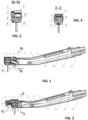
figure 1 represents a vertical longitudinal cross-section of a dental handpiece (along a length of a handle, side view) according to a first embodiment of the invention, wherein an optical sensor is located (along the length of the handle) between a drill bit and the handle; -
figure 2 represents a vertical transversal cross-section of the dental handpiece (across its handle, N-N plan view) according to the first embodiment of the invention, as shown infigure 1 ; -
figure 3 represents a vertical longitudinal cross-section of a dental handpiece (along a length of a handle, side view) according to a second embodiment of the invention, wherein a drill bit is located (along the length of the handle) between an optical sensor and the handle; -
figure 4 represents a vertical transversal cross-section of the dental handpiece (across its handle, B-B plan view) according to the second embodiment of the invention, as shown infigure 3 ; -
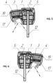
figures 5 and 6 represent vertical transversal (across a handle) cross-sections of the dental handpiece according to a third embodiment of the invention, wherein an optical sensor is oriented perpendicularly to the handle of the housing, and, consequently, a transparent shielding window receives an air flow sideways from a longitudinal axis of the handle; -
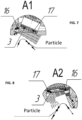
figure 7 represents an element A1 of the dental handpiece, said element representing an enlarged view of main assemblies according to the first embodiment of the invention, as shown infigures 1 and 2 ; -
figure 8 represents an element A2 of the dental handpiece, said element representing an enlarged view of main assemblies according to the second embodiment of the invention, as shown infigures 3 and 4 ; -
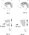
figure 9 represents a vertical longitudinal cross-section view of a working end part of the dental handpiece housing (along the length of its handle, side view) that demonstrates an example with an air jet turning angle of 120 degrees when a protrusion is inclined 80 degrees; -
figure 10 represents a vertical longitudinal cross-section view of a working end part of the dental handpiece housing (along a length of its handle, side view) that demonstrates an example with an air jet turning angle of 140 degrees when a protrusion is inclined 60 degrees; -
figure 11 represents a vertical longitudinal cross-section view of a diffuser part that enables an outflow speed of 3 m/s with an equivalent round section diameter of 2,8 mm; -
figure 12 represents a vertical longitudinal cross-section view of a diffuser part that enables an outflow speed of 50 m/s with an equivalent round section diameter of 0,7 mm; -
figure 13 represents a vertical longitudinal cross-section view of a working end part of the dental handpiece housing (along a length of its handle, side view) that demonstrates an example with an angle 0° between a direction of an air curtain outflow and a transparentshielding window plane 3, when an aperture angle of adiffuser 16 outlet section is 0°; -
figure 14 represents a vertical longitudinal cross-section view of a working end part of the dental handpiece housing (along a length of its handle, side view) that demonstrates an example with anangle 15° between a direction - of an air curtain outflow and a transparent
shielding window plane 3, when an aperture angle of adiffuser 16 outlet section is 30. -
Figures 1 to 14 indicate: - 1 - Rotor group.
- 2 - Collet clamp button.
- 3 - Transparent shield glass (window).
- 4 - Optical sensor (camera).
- 5 - Optical sensor sleeve.
- 6 - Handpiece handle.
- 7 - Board latch.
- 8 - Midwest 4 adapter.
- 9 - Connector socket.
- 10 - Camera module board.
- 11 - Compressed air supplying tube.
- 12 - Drill bit.
- 13 - Exhaust air vent.
- 14 - Water feed to a sprayer.
- 15 - Air feed to a sprayer.
- 16 - Diffuser.
- 17 - Light-emitting diode.
- 18 - Handpiece housing.
- 19 - Handpiece cover.
- A compressed air source (dental set compressor) is not shown in the figures.
- According to
figures 1 to 14 , a dental handpiece comprises ahandle 6 and ahousing 18 with an optical emission source represented by at least one light-emittingdiode 17 connected to an electric power supply. Said handpiece having anoptical sensor 4 adapted to be connected to visualization devices, not shown in the figures. - The
housing 18 has atransparent shielding window 3 of the optical sensor. The handpiece has a device for supplying compressed air on the transparent shielding window, also shown as a compressedair supplying tube 11. Thehousing 18 has an aperture for supplying compressed air to the transparent shielding window connected to the device for supplying compressed air. Adiffuser 16 is located in the aperture, said diffuser being designed so as to generate an air jet forming an air curtain before thetransparent shielding window 3. - In a first embodiment, the
diffuser 16 is located from a working end of thehousing 18 and is designed so as to direct the air jet away from the working end of thehousing 18 towards the handle (that is, a diffuser outlet is directed to the handle): seefigures 1 and 2 . - In a second embodiment, the
diffuser 16 is located from a working end of thehousing 18 and is designed so as to direct the air jet away from thehandle 6, that is, an outlet of the diffuser is directed away from the handle (along its length). Thehousing 18 comprises a protrusion located from the working end, said protrusion having a surface shape which turns the air jet to 120°-140°: seefigures 3-4 ,9-10 . - In a third embodiment, the
diffuser 16 is located from thetransparent shielding window 3 and oriented perpendicularly to thehandle 6. Thediffuser 16 is designed so as to direct the air jet sideways from thehandle 6 of thehousing 18, that is, an outlet of thediffuser 16 is directed sideways from thehandle 6. Thehousing 18 comprises a protrusion located from the working end, said protrusion having a surface shape which turns the air jet to 120°-140°: seefigures 5-6 ,9-10 . - The
diffuser 16 is also preferably designed so as to generate the air jet with the outflow speed ranging from 6 m/s to 50 m/s and forming an angle from 0° to 15° with a plane of thetransparent shielding window 3. - Said dental handpiece is also designed with several air supply options: direct (without turning the air curtain flow as shown in the
figures 1 ,7 ) and reverse (with turning of the air curtain, as shown in thefigures 3 ,5-6 ,8-10 ), and in different locations of theoptical sensor 4 relative to a drill bit 12 (in front of, behind, to the right, to the left, relative to a longitudinal axis of the drill bit 12), as is evident fromfigures 1-6 . - The dental handpiece operates as follows. Below is the most exhaustive example of the embodiment of the invention, however, said example does not limit other applications of the invention.
- Example. A compressed air is supplied from a dental unit compressor through a compressed
air supplying tube 11 as a channeled air jet to ahousing 18. When the air passes through thehousing 18, it goes to adirectional diffuser 16 that forms a flat jet directed at an angle from 1 to 15 degrees to thehousing 18 surface with an outflow speed ranging from 6 m/s to 50 m/s. The high-speed jet does not allow foreign particles having densities and speeds typical for dental interventions pass through its core and moves them away from thetransparent shielding window 3 of the optical sensor (camera) 4. - Quantitative attributes of the technical parameters such as an the air jet turning angle, the air jet outflow speed and the angle between the air jet outflow and the
transparent shielding window 3 plane in the range of continuously changing variables can be adjusted by varying a protrusion and thediffuser 16 geometry. - The selection of a specific range of technical parameter values is made experimentally and depends on the efficiency of optical sensor (camera) 4 shielding window blowing. Blowing efficiency control method shall be a visual control of readability of the image transferred from the
optical sensor 4 and contaminated with artifacts due to foreign particles and liquid droplets getting onto thetransparent shielding window 3. The number of image artifacts shall be assumed as a criterion of blowing efficiency in four tiers: - "none" - no visible artifacts from foreign particles and liquid droplets;
- "moderate" - foreign particles and liquid droplets are not retained on the surface of the
transparent shielding window 3 and do not affect the readability of the transferred image; - "medium" - foreign particles and liquid droplets remain on the surface of the
transparent shielding window 3 and affect the image transferred from theoptical sensor 4. However, readability remains sufficient to direct the dental handpiece in the operating environment; - "severe" - foreign particles and liquid droplets remain on the surface of the
transparent shielding window 3, making the image from theoptical sensor 4 unreadable and not suitable for correct orientation of the dental handpiece in the operating environment. - Air jet rotation angle is adjusted in the range from 120° to 140° by adjusting the shape of the protrusion surface directed at the
diffuser 16. A protrusion incline angle shall be the geometrical parameter for an airjet turning angle. The protrusion incline angle is found between the tangential line to the margin of the concave surface and the plane of thetransparent shielding window 3. - See Table 1 for the relationship between the air jet turning angles, image artifact grade, and the above geometrical parameter (i.e. protrusion incline angle).
Table 1. Dependence of air jet rotation angles and image artifact grade from protrusion incline angle. No Air jet turning angle, degree Protrusion incline angle, degree Image artifact grade 1 115 85 Medium 2 120 80 Moderate 3 125 75 Moderate 4 130 70 None 5 135 65 None 6 140 60 None - See
figures 9 and 10 for the examples of the embodiments of the invention with border values in the specified range, namely: -
figure 9 shows the example with the air jet rotation angle of 120 degrees which results in moderate image artifact grade, with the protrusion incline angle of 80 degrees; -
figure 10 shows the example with the air jet rotation angle of 140 degrees which results in no image artifacts (grade "none"), with the protrusion incline angle of 60 degrees. - Air jet outflow was adjusted in the range from 6 m/s to 50 m/s by adjusting the
diffuser 16 outlet cross-section area. The geometrical parameter characterizing air jet outflow speed was round section diameter with the same area as thediffuser 16 outlet cross-section. See Table 2 for the relationship between air jet outflow, image artifact grade, and the above geometrical parameter.Table 2. Dependence of air jet outflow speed and image artifact grade from equivalent round section diameter. No Air jet outflow speed, m/s Equivalent round section diameter, mm Image artifact grade 1 3 2,8 Severe 2 6 2,0 Medium 3 10 1,6 Moderate 4 20 1,1 Moderate 5 30 0,9 Moderate 6 40 0,8 None 7 50 0,7 None - See
Figures 11 and 12 for the examples of the embodiments of the invention with border values in the specified range, namely: -
figure 11 shows an example with an air jet outflow speed of 3 m/s and, respectively, severe image artifact grade, with an equivalent round section diameter of 2,8 mm; -
figure 12 shows an example with an air jet outflow speed of 50 m/s and, respectively, no image artifacts, with an equivalent round section diameter of 0,7 mm. - The angle between the air curtain outflow direction and shielding window plane was adjusted in the range from 0 to 15 degrees by adjusting the
diffuser 16 outlet cross-section aperture angle. Thediffuser 16 outlet cross-section aperture angle was assumed as the characteristic geometrical parameter. See Table 3 for the dependence of the angle between the direction of the air curtain outflow direction and shielding window plane and image artifact grade on the above geometrical parameter.Table 3. Dependence of the angle between the direction of the air curtain outflow direction and shielding window 3 plane and image artifact grade on thediffuser 16 outlet cross-section aperture angle.No Angle between the direction of the air curtain outflow direction and shielding window 3 plane,degrees Diffuser 16 outlet cross-section aperture angle, degrees Image artifact grade 1 0 0 None 2 2,5 5 None 3 5 10 Moderate 4 7,5 15 Moderate 5 10 20 Medium 6 12,5 25 Medium 7 15 30 Medium 8 17,5 35 Severe - See
Figure 3 for the examples of the embodiments of the invention with border values in the specified range, namely: -
figure 13 shows an example with the angle between the direction of the air curtain outflow direction and shieldingwindow 3 plane equaling 0° and no image artifacts, respectively, at thediffuser 16 outlet cross-section aperture angle of 0°; -
figure 14 shows an example with the angle between the direction of the air curtain outflow direction and shieldingwindow 3 plane equaling 15° and medium image artifact grade, respectively, at thediffuser 16 outlet cross-section aperture angle of 30°. - Therefore, (see
figures 1-14 ), the invention relates to a dental handpiece comprising: - a
handle 6, - a
housing 18 comprising an optical emission source represented by at least one light-emittingdiode 17 connected to an electric power supply, - an
optical sensor 4 adapted to be connected to visualization devices. - In a first embodiment of the invention (
Figures 1-2 ,7 ), thediffuser 16 is located from a working end of thehousing 18. Thediffuser 16 is designed so as to direct the air jet away from the working end of thehousing 18 longitudinally towards thehandle 6. - In an alternative second embodiment of the invention (
Figures 3-4 ,8 ), thediffuser 16 is located from the working end of thehousing 18. Under these conditions, thediffuser 16 is designed so as to direct the air jet away from the handle 6 (that is, along the length of the handle 6). Thehousing 18 has a protrusion located from the working end. The protrusion has a surface shape which turns the air jet outgoing from thediffuser 16 in a first range from 120° to 140° (Figures 9 to 10 ). - In an alternative second embodiment of the invention (
Figures 5-6 ), thediffuser 16 is located from the working end of thehousing 18 and oriented perpendicularly to thehandle 6. Thediffuser 16 is designed so as to direct the air jet sideways from thehousing 18handle 6. Thehousing 18 comprises a protrusion located from the working end. The protrusion has a surface shape which turns the air jet outgoing from thediffuser 16 by the first angle in the first range from 120° to 140° (Figures 9-10 ). - Preferably, the
diffuser 16 is designed so as to generate the air jet with an outflow speed ranging from 6 m/s to 50 m/s (Figures 11-12 ). This air jet outflow forms a second angle with a plane of thetransparent shielding window 3, said second angle being comprised in a second range from 0° to 15° (Figures 13 to 14 ). - The claimed dental handpiece may be implemented by a person skilled in the art in practice and ensures that the claimed objectives are met after implementation, which leads to the conclusion that the invention meets the requirement of "industrial applicability".
- A series of real-life tests was performed to confirm the operability of the proposed dental handpiece. As an example, the preparation of the upper 8th tooth with a compound cavity was recorded on the video. The preparation was made using a standard air turbine handpiece with standard water spraying of the intervention area. The sensor shielding window was located in the range from 25 mm to 28 mm from the preparation area at the angle of 60 to 70 degrees. No additional optics protection measures were taken, only standard-grade dental equipment and tools specific for such interventions were used. The video shows that, under the conditions of active water supplying and high-intensity spraying, the
transparent shielding window 3 is not polluted by solid enamel and dentine particles cut by rotating tools, and that thecamera 4 continues operation throughout the intervention. - Therefore, these novel features make it possible to achieve the claimed technical results, namely to ensure reliable protection of the optical sensor by implementing an air curtain. Said dental handpiece is also designed with several air feed options: direct and reverse (with turning of the air curtain flow) and in different locations of the
optical sensor 4 relative to the drill bit 12 (in front of, behind, to the right, to the left, relative to thedrill bit 12 longitudinal axis).
Claims (5)
- A dental handpiece including:• a handle (6),• a housing (18) comprising an optical emission source represented by at least one light-emitting diode (17) connected to an electric power supply,• an optical sensor (4) adapted to be connected to visualization devices,characterized in that the housing (18) comprises a transparent shielding window (3) adapted to shield the optical sensor (4), in that the dental handpiece additionally comprises a device for supplying compressed air on the transparent shielding window (3), in that the housing (18) additionally comprises an aperture for supplying compressed air to the transparent shielding window (3), said aperture being connected to the device for supplying compressed air, and in that a diffuser (16) is located in the aperture, said diffuser being designed so as to generate an air jet which forms an air curtain in front of the transparent shielding window (3).
- The dental handpiece according to claim 1, characterized in that the diffuser (16) is located from a working end of the housing (18), and in that the diffuser (16) is designed so as to direct the air jet away from the working end of the housing (18) longitudinally towards the handle (6).
- The dental handpiece according to claim 1, characterized in that the diffuser (16) is located from a working end of the housing (18), in that said diffuser (16) is designed so as to direct the air jet longitudinally away from the handle (6), in that the housing (18) comprises a protrusion located from the working end, and in that the protrusion has a surface shape which turns the air jet outgoing from the diffuser (16) to a first angle comprising in a first range from 120° to 140°.
- The dental handpiece according to claim 1, characterized in that the diffuser (16) is oriented perpendicularly to the handle (6), in that the diffuser (16) is designed so as to direct the air jet sideways from the handle (6), in that the housing (18) comprises a protrusion located from the working end, and in that said protrusion has a surface shape which turns the air jet outgoing from the diffuser (16) to a the first angle comprising in a first range from 120° to 140°.
- The dental handpiece according to claim 1, characterized in that the diffuser (16) is designed so as to generate the air jet with an outflow speed ranging from 6 m/s to 50 m/s, and in that the outflow speed forms a second angle with a plane of the transparent shielding window (3), said second angle being comprised in a second range from 0° to 15°.
Applications Claiming Priority (2)
| Application Number | Priority Date | Filing Date | Title |
|---|---|---|---|
| RU2021131532A RU2772017C1 (en) | 2021-10-27 | Dental handpiece | |
| PCT/IB2022/060356 WO2023073616A1 (en) | 2021-10-27 | 2022-10-27 | Dental handpiece |
Publications (1)
| Publication Number | Publication Date |
|---|---|
| EP4424225A1 true EP4424225A1 (en) | 2024-09-04 |
Family
ID=85225326
Family Applications (1)
| Application Number | Title | Priority Date | Filing Date |
|---|---|---|---|
| EP22856988.5A Pending EP4424225A1 (en) | 2021-10-27 | 2022-10-27 | Dental handpiece |
Country Status (5)
| Country | Link |
|---|---|
| US (1) | US20250000352A1 (en) |
| EP (1) | EP4424225A1 (en) |
| JP (1) | JP2024538270A (en) |
| CN (1) | CN118890997A (en) |
| WO (1) | WO2023073616A1 (en) |
Cited By (1)
| Publication number | Priority date | Publication date | Assignee | Title |
|---|---|---|---|---|
| WO2026074519A1 (en) * | 2024-10-04 | 2026-04-09 | Михальский Александр | Dental handpiece |
Families Citing this family (1)
| Publication number | Priority date | Publication date | Assignee | Title |
|---|---|---|---|---|
| CN121941468A (en) * | 2023-08-09 | 2026-04-28 | 海利安特拉医疗创新私人有限公司 | A digital dental handpiece with surgical field marking and an improved cooling mechanism |
Family Cites Families (10)
| Publication number | Priority date | Publication date | Assignee | Title |
|---|---|---|---|---|
| JP3151009B2 (en) | 1991-07-30 | 2001-04-03 | 株式会社モリタ製作所 | Dental treatment instrument with monitor function |
| DE10043749A1 (en) * | 2000-09-05 | 2002-03-14 | Kaltenbach & Voigt | Dental handpiece has image acquisition arrangement, light stimulation arrangement, whereby irradiated region is in center of detected area, and fluorescence detector |
| IT1320124B1 (en) * | 2000-12-20 | 2003-11-18 | Faro Spa | PERFECTED DEVICE FOR DENTAL INTERVENTIONS. |
| US9050036B2 (en) * | 2007-06-19 | 2015-06-09 | Minimally Invasive Devices, Inc. | Device for maintaining visualization with surgical scopes |
| EP2337519A4 (en) | 2008-09-24 | 2012-04-18 | Dentsply Int Inc | IMAGING DEVICE FOR DENTAL INSTRUMENTS AND INTRAORAL VISUALIZATION METHODS |
| FR2974721A1 (en) * | 2011-05-02 | 2012-11-09 | Albert Edmond Andre Jean Leon Guenier | Video endoscope for use by dentist, has housing that is located in distal portion of base that remains attached to offset articulated arm, where rotation of tube in housing of base is made by friction |
| JP6262936B2 (en) | 2012-08-31 | 2018-01-17 | 株式会社吉田製作所 | Camera built-in handpiece |
| JP6324680B2 (en) * | 2013-08-02 | 2018-05-16 | 株式会社吉田製作所 | Camera window handpiece with built-in anti-fogging function |
| PL245671B1 (en) * | 2019-04-20 | 2024-09-16 | Lassmann Lukasz | Oral imaging device |
| EP3769658A1 (en) * | 2019-07-23 | 2021-01-27 | National University of Ireland Galway | A scope |
-
2022
- 2022-10-27 JP JP2024525297A patent/JP2024538270A/en active Pending
- 2022-10-27 WO PCT/IB2022/060356 patent/WO2023073616A1/en not_active Ceased
- 2022-10-27 EP EP22856988.5A patent/EP4424225A1/en active Pending
- 2022-10-27 CN CN202280079060.XA patent/CN118890997A/en active Pending
- 2022-10-27 US US18/704,450 patent/US20250000352A1/en active Pending
Cited By (1)
| Publication number | Priority date | Publication date | Assignee | Title |
|---|---|---|---|---|
| WO2026074519A1 (en) * | 2024-10-04 | 2026-04-09 | Михальский Александр | Dental handpiece |
Also Published As
| Publication number | Publication date |
|---|---|
| US20250000352A1 (en) | 2025-01-02 |
| JP2024538270A (en) | 2024-10-18 |
| CN118890997A (en) | 2024-11-01 |
| WO2023073616A1 (en) | 2023-05-04 |
Similar Documents
| Publication | Publication Date | Title |
|---|---|---|
| US20250295301A1 (en) | Dental handpiece | |
| EP4424225A1 (en) | Dental handpiece | |
| JP6324680B2 (en) | Camera window handpiece with built-in anti-fogging function | |
| US10631951B2 (en) | Laser based computer controlled dental preparation system | |
| ES2868999T3 (en) | Dental laser appliance and method of use with interchangeable handpiece and variable pedal | |
| US4174571A (en) | Method for cleaning teeth | |
| DE4239829A1 (en) | Medical or dental treatment appliance with laser energised probe - has hand-held termination for fibre optic probe with two air cooling conduits and water conduit for flushing and cooling at tip. | |
| US4176453A (en) | Dental drill | |
| US20100125291A1 (en) | Drill and flavored fluid particles combination | |
| US20230149137A1 (en) | Dental Suction Device, and Dental Suction Device and Instrument Assembly | |
| KR20110102298A (en) | Laser treatment device and method for treating biological tissue | |
| EP0523506B2 (en) | Handpiece for stomatological use of laser light | |
| JPH01204637A (en) | Endoscope | |
| CN109480355A (en) | Combined type oral cavity doctor's protective face mask | |
| JPH05137808A (en) | Protector used for coating operation or the like | |
| US3815241A (en) | Dental handpiece with built-in coolant duct | |
| EP4400026A1 (en) | Intraoral endoscope | |
| RU2782094C1 (en) | Dental hand | |
| JPH05344982A (en) | Medical laser device | |
| RU2772017C1 (en) | Dental handpiece | |
| DE19860485B4 (en) | Laser transmission system and hand instrument with such a system for use with laser devices | |
| DE102015102149B3 (en) | Device for the laser preparation of teeth for dentures and root treatments | |
| DE2944397A1 (en) | Precious metal dust recovery device for dentistry - comprises transparent sealed shell surrounding working point to trap dust | |
| RU2849129C1 (en) | Dental tip | |
| JPS6139454Y2 (en) |
Legal Events
| Date | Code | Title | Description |
|---|---|---|---|
| STAA | Information on the status of an ep patent application or granted ep patent |
Free format text: STATUS: UNKNOWN |
|
| STAA | Information on the status of an ep patent application or granted ep patent |
Free format text: STATUS: THE INTERNATIONAL PUBLICATION HAS BEEN MADE |
|
| PUAI | Public reference made under article 153(3) epc to a published international application that has entered the european phase |
Free format text: ORIGINAL CODE: 0009012 |
|
| STAA | Information on the status of an ep patent application or granted ep patent |
Free format text: STATUS: REQUEST FOR EXAMINATION WAS MADE |
|
| 17P | Request for examination filed |
Effective date: 20240422 |
|
| AK | Designated contracting states |
Kind code of ref document: A1 Designated state(s): AL AT BE BG CH CY CZ DE DK EE ES FI FR GB GR HR HU IE IS IT LI LT LU LV MC ME MK MT NL NO PL PT RO RS SE SI SK SM TR |
|
| TPAC | Observations filed by third parties |
Free format text: ORIGINAL CODE: EPIDOSNTIPA |
|
| DAV | Request for validation of the european patent (deleted) | ||
| DAX | Request for extension of the european patent (deleted) |