EP4424222A1 - Portable handheld cleaning tool - Google Patents
Portable handheld cleaning tool Download PDFInfo
- Publication number
- EP4424222A1 EP4424222A1 EP23159175.1A EP23159175A EP4424222A1 EP 4424222 A1 EP4424222 A1 EP 4424222A1 EP 23159175 A EP23159175 A EP 23159175A EP 4424222 A1 EP4424222 A1 EP 4424222A1
- Authority
- EP
- European Patent Office
- Prior art keywords
- shaft portion
- surface cleaning
- cleaning tool
- driveshaft
- cleaning
- Prior art date
- Legal status (The legal status is an assumption and is not a legal conclusion. Google has not performed a legal analysis and makes no representation as to the accuracy of the status listed.)
- Granted
Links
Images




Classifications
-
- A—HUMAN NECESSITIES
- A47—FURNITURE; DOMESTIC ARTICLES OR APPLIANCES; COFFEE MILLS; SPICE MILLS; SUCTION CLEANERS IN GENERAL
- A47L—DOMESTIC WASHING OR CLEANING; SUCTION CLEANERS IN GENERAL
- A47L11/00—Machines for cleaning floors, carpets, furniture, walls, or wall coverings
- A47L11/28—Floor-scrubbing machines, motor-driven
- A47L11/282—Floor-scrubbing machines, motor-driven having rotary tools
-
- A—HUMAN NECESSITIES
- A46—BRUSHWARE
- A46B—BRUSHES
- A46B13/00—Brushes with driven brush bodies or carriers
- A46B13/02—Brushes with driven brush bodies or carriers power-driven carriers
- A46B13/04—Brushes with driven brush bodies or carriers power-driven carriers with reservoir or other means for supplying substances
-
- A—HUMAN NECESSITIES
- A46—BRUSHWARE
- A46B—BRUSHES
- A46B11/00—Brushes with reservoir or other means for applying substances, e.g. paints, pastes, water
- A46B11/06—Brushes with reservoir or other means for applying substances, e.g. paints, pastes, water connected to supply pipe or to other external supply means
-
- A—HUMAN NECESSITIES
- A46—BRUSHWARE
- A46B—BRUSHES
- A46B11/00—Brushes with reservoir or other means for applying substances, e.g. paints, pastes, water
- A46B11/06—Brushes with reservoir or other means for applying substances, e.g. paints, pastes, water connected to supply pipe or to other external supply means
- A46B11/063—Brushes with reservoir or other means for applying substances, e.g. paints, pastes, water connected to supply pipe or to other external supply means by means of a supply pipe
-
- A—HUMAN NECESSITIES
- A46—BRUSHWARE
- A46B—BRUSHES
- A46B13/00—Brushes with driven brush bodies or carriers
- A46B13/001—Cylindrical or annular brush bodies
-
- A—HUMAN NECESSITIES
- A46—BRUSHWARE
- A46B—BRUSHES
- A46B13/00—Brushes with driven brush bodies or carriers
- A46B13/008—Disc-shaped brush bodies
-
- A—HUMAN NECESSITIES
- A46—BRUSHWARE
- A46B—BRUSHES
- A46B13/00—Brushes with driven brush bodies or carriers
- A46B13/02—Brushes with driven brush bodies or carriers power-driven carriers
-
- A—HUMAN NECESSITIES
- A46—BRUSHWARE
- A46B—BRUSHES
- A46B5/00—Brush bodies; Handles integral with brushware
- A46B5/002—Brush bodies; Handles integral with brushware having articulations, joints or flexible portions
- A46B5/0033—Brush bodies; Handles integral with brushware having articulations, joints or flexible portions bending or stretching or collapsing
- A46B5/005—Brushes with a telescopic or similarly moveable portion
-
- A—HUMAN NECESSITIES
- A46—BRUSHWARE
- A46B—BRUSHES
- A46B7/00—Bristle carriers arranged in the brush body
- A46B7/06—Bristle carriers arranged in the brush body movably during use, i.e. the normal brushing action causing movement
- A46B7/10—Bristle carriers arranged in the brush body movably during use, i.e. the normal brushing action causing movement as a rotating cylinder
-
- A—HUMAN NECESSITIES
- A47—FURNITURE; DOMESTIC ARTICLES OR APPLIANCES; COFFEE MILLS; SPICE MILLS; SUCTION CLEANERS IN GENERAL
- A47L—DOMESTIC WASHING OR CLEANING; SUCTION CLEANERS IN GENERAL
- A47L11/00—Machines for cleaning floors, carpets, furniture, walls, or wall coverings
- A47L11/40—Parts or details of machines not provided for in groups A47L11/02 - A47L11/38, or not restricted to one of these groups, e.g. handles, arrangements of switches, skirts, buffers, levers
- A47L11/4063—Driving means; Transmission means therefor
- A47L11/4069—Driving or transmission means for the cleaning tools
-
- A—HUMAN NECESSITIES
- A47—FURNITURE; DOMESTIC ARTICLES OR APPLIANCES; COFFEE MILLS; SPICE MILLS; SUCTION CLEANERS IN GENERAL
- A47L—DOMESTIC WASHING OR CLEANING; SUCTION CLEANERS IN GENERAL
- A47L11/00—Machines for cleaning floors, carpets, furniture, walls, or wall coverings
- A47L11/40—Parts or details of machines not provided for in groups A47L11/02 - A47L11/38, or not restricted to one of these groups, e.g. handles, arrangements of switches, skirts, buffers, levers
- A47L11/408—Means for supplying cleaning or surface treating agents
- A47L11/4088—Supply pumps; Spraying devices; Supply conduits
-
- B—PERFORMING OPERATIONS; TRANSPORTING
- B08—CLEANING
- B08B—CLEANING IN GENERAL; PREVENTION OF FOULING IN GENERAL
- B08B1/00—Cleaning by methods involving the use of tools
- B08B1/10—Cleaning by methods involving the use of tools characterised by the type of cleaning tool
- B08B1/12—Brushes
-
- B—PERFORMING OPERATIONS; TRANSPORTING
- B08—CLEANING
- B08B—CLEANING IN GENERAL; PREVENTION OF FOULING IN GENERAL
- B08B1/00—Cleaning by methods involving the use of tools
- B08B1/30—Cleaning by methods involving the use of tools by movement of cleaning members over a surface
- B08B1/32—Cleaning by methods involving the use of tools by movement of cleaning members over a surface using rotary cleaning members
- B08B1/34—Cleaning by methods involving the use of tools by movement of cleaning members over a surface using rotary cleaning members rotating about an axis parallel to the surface
-
- B—PERFORMING OPERATIONS; TRANSPORTING
- B08—CLEANING
- B08B—CLEANING IN GENERAL; PREVENTION OF FOULING IN GENERAL
- B08B1/00—Cleaning by methods involving the use of tools
- B08B1/30—Cleaning by methods involving the use of tools by movement of cleaning members over a surface
- B08B1/32—Cleaning by methods involving the use of tools by movement of cleaning members over a surface using rotary cleaning members
- B08B1/36—Cleaning by methods involving the use of tools by movement of cleaning members over a surface using rotary cleaning members rotating about an axis orthogonal to the surface
-
- B—PERFORMING OPERATIONS; TRANSPORTING
- B08—CLEANING
- B08B—CLEANING IN GENERAL; PREVENTION OF FOULING IN GENERAL
- B08B3/00—Cleaning by methods involving the use or presence of liquid or steam
- B08B3/02—Cleaning by the force of jets or sprays
- B08B3/026—Cleaning by making use of hand-held spray guns; Fluid preparations therefor
-
- B—PERFORMING OPERATIONS; TRANSPORTING
- B08—CLEANING
- B08B—CLEANING IN GENERAL; PREVENTION OF FOULING IN GENERAL
- B08B3/00—Cleaning by methods involving the use or presence of liquid or steam
- B08B3/02—Cleaning by the force of jets or sprays
- B08B3/026—Cleaning by making use of hand-held spray guns; Fluid preparations therefor
- B08B3/028—Spray guns
-
- A—HUMAN NECESSITIES
- A46—BRUSHWARE
- A46B—BRUSHES
- A46B2200/00—Brushes characterized by their functions, uses or applications
- A46B2200/30—Brushes for cleaning or polishing
- A46B2200/3033—Household brush, i.e. brushes for cleaning in the house or dishes
-
- A—HUMAN NECESSITIES
- A46—BRUSHWARE
- A46B—BRUSHES
- A46B2200/00—Brushes characterized by their functions, uses or applications
- A46B2200/30—Brushes for cleaning or polishing
- A46B2200/3066—Brush specifically designed for use with street cleaning machinery
Definitions
- the invention relates to a portable handheld cleaning tool.
- Handheld electrically driven cleaning tools are known.
- such cleaning tools include a brush rotatable by an electric motor and a handle for a user to grasp and direct the rotatable brush along or over surfaces or objects to be cleaned.
- CN 206453464 U discloses a motor-driven cleaning brush.
- the cleaning brush comprises a brush head and a rotatory gear motor for driving a brush arranged at the brush head.
- a telescopic link including a handle is arranged for adjusting a length of a pole at which the brush head is arranged.
- CN206836552 U discloses a cleaning brush of a similar kind.
- a cleaning tool comprising a rotatable brush being devised for wet cleaning of surfaces.
- a portable handheld cleaning tool having the features defined in the independent claim is provided.
- a portable handheld cleaning tool comprising a handle portion, a surface cleaning portion, a shaft portion extending between the handle portion and the surface cleaning portion, a rotatable brush arranged in the surface cleaning portion, an electric motor arranged in the handle portion, and a driveshaft extending from the electric motor through the shaft portion to the surface cleaning portion.
- the shaft portion is removable from the handle portion and from the surface cleaning portion.
- the cleaning tool is configured for supply of water at the surface cleaning portion and comprises a water supply coupling element arranged at the handle portion, at least one water outlet nozzle arranged in the surface cleaning portion, and a water conduit extending between the water supply coupling element and the at least one water outlet nozzle.
- the shaft portion comprises a water channel forming part of the water conduit and extending from a first end portion of the shaft portion at the handle portion to a second end portion of the shaft portion at the surface cleaning portion.
- the cleaning tool comprises a water supply coupling element arranged at the handle portion, at least one water outlet nozzle arranged in the surface cleaning portion, and a water conduit extending between the water supply coupling element and the at least one water outlet nozzle, and since the shaft portion comprises a water channel forming part of the water conduit and extending from a first end portion of the shaft portion at the handle portion to a second end portion of the shaft portion at the surface cleaning portion - the cleaning tool is devised for wet cleaning.
- the cleaning tool is devised for connecting a water supply e.g., via a water hose, to the water supply coupling element at the handle portion and conducting water from the handle portion via the water channel in the shaft portion to the at least one water outlet nozzle in the surface cleaning portion for provision of the water to the surface cleaning portion and/or a surface being cleaned with the cleaning tool.
- a cleaning tool comprising a removable shaft portion.
- a thereto connected water hose is arranged close to a user of the cleaning tool. The user can thus, easily reach and control the water hose.
- the portable handheld cleaning tool is alternatively referred to as the cleaning tool.
- the cleaning tool may be a domestically or commercially utilised cleaning tool.
- the portable handheld cleaning tool is portable and handheld by having a weight such that a user of the cleaning tool firstly, is able to carry the cleaning tool and secondly, handle the cleaning tool as it is being used for cleaning a surface.
- the cleaning tool may be suspended from e.g., a shoulder strap or a harness worn by the user while handling the cleaning tool.
- the handle portion is configured for a user to grasp.
- the handle portion may comprise one or two or more handles for grasping by a user when handling the cleaning tool.
- the surface cleaning portion is configured for engaging with a surface to be cleaned.
- the surface to be cleaned may be e.g., a floor surface, a wall surface, etc.
- the surface to be cleaned may be e.g., an outdoor surface such as a surface of a patio, a driveway, a façade, a planking, etc.
- the surface to be cleaned may be a surface of an object such as of e.g., a vehicle, a piece of furniture, a garden ornament, a boat, etc.
- the shaft portion extending between the handle portion and the surface cleaning portion may have a length within a range of 0.3 - 3 meters. Since the shaft portion is removable from the handle portion and from the surface cleaning portion, a first shaft portion having a first length may be replaced with a second shaft portion having a second length different from the first length. Accordingly, a suitable length shaft portion may be selected for a particular cleaning task.
- An alternative may be for the removable shaft portion to comprise a telescopic shaft portion, which is adjustable to a suitable length for a particular cleaning task.
- the rotatable brush that is arranged in the surface cleaning portion is configured for engaging with a surface to be cleaned.
- the rotatable brush or the entire surface cleaning portion may be exchangeable.
- the rotatable brush may have a rotational axis arranged to extend substantially perpendicularly to a surface to be cleaned or a rotational axis arranged to extend substantially in parallel with a surface to be cleaned.
- the surface cleaning portion may comprise more than one rotatable brush.
- Different surface cleaning portions may comprise rotatable brushes of different kinds.
- a suitable surface cleaning portion may be selected from a set of different surface cleaning portions and be connected to the shaft portion for a particular surface cleaning task.
- the electric motor may be powered by a battery arranged in the cleaning tool or carried by a user of the cleaning tool e.g., in a backpack or at a belt around the waist of the user.
- the electric motor may be powered by mains power via a power cord.
- the electric motor is arranged in the handle portion and the driveshaft extends through the shaft portion to the surface cleaning portion, a good weight distribution within the cleaning tool is ensured for holding and handling the cleaning tool e.g., in comparison with prior art cleaning tools having the electric motor arranged close to the rotatable brush. Moreover, a cost-efficient solution is provided for changing between different surface cleaning portions. Namely, since one and the same electric motor arranged in the handle portion can be utilised for driving the rotatable brush of different exchangeable surface cleaning portions, not each surface cleaning portion requires its own electric motor.
- the driveshaft may be journaled in the shaft portion.
- the water supply coupling element may comprise a quick coupling for connecting e.g., a garden hose thereto, also referred to as quick-connect garden hose coupling.
- the at least one water outlet nozzle arranged in the surface cleaning portion may be directed to distribute water over the rotatable brush and/or the surface to be cleaned.
- the water channel comprised in the shaft portion is connectable to a portion of the water conduit in the handle portion and to a portion of the water conduit in the surface cleaning portion.
- the water channel is uncoupled from the portion of the water conduit in the handle portion.
- the surface cleaning portion is removed from the shaft portion, the water channel is uncoupled from the portion of the water conduit in the surface cleaning portion.
- the shaft portion may comprise a duct through which the driveshaft extends, wherein at least part of the shaft portion may comprise a tube made from extruded material, and wherein at least part of the water channel and at least part of the duct are formed by the extruded material in one piece, as portions of the tube.
- a shaft portion that can be cost efficiently manufacture may be provided.
- the cleaning tool may comprise a first water conduit interface between the handle portion and the shaft portion, wherein the first water conduit interface comprises a first socket arranged in the shaft portion or in the handle portion and a first protruding tube end portion arranged in the other of the shaft portion and the handle portion, and wherein the first protruding tube end portion fits into the first socket.
- the first water conduit interface forms part of the water conduit and provides a releasable connection between the water channel in the shaft portion and the portion of the water conduit in the handle portion.
- the shaft portion at its first end portion may comprise a first bearing for the driveshaft.
- the driveshaft may be journaled in the shaft portion to ensure reliable rotation of the driveshaft and accordingly, of the rotatable brush during use of the cleaning tool.
- the cleaning tool may comprise a second water conduit interface between the shaft portion and the surface cleaning portion, wherein the second water conduit interface comprises a second socket arranged in the shaft portion or in the surface cleaning portion and a second protruding tube end portion arranged in the other of the shaft portion and the surface cleaning portion, and wherein the second protruding tube end portion fits into the second socket.
- the second water conduit interface forms part of the water conduit and provides a releasable connection between a portion of the water conduit in the surface cleaning portion and the water channel in the shaft portion.
- the shaft portion at its second end portion may comprise a second bearing for the driveshaft.
- the driveshaft may be journaled in the shaft portion to ensure reliable operation of the driveshaft and accordingly, of the rotatable brush during use of the cleaning tool.
- the surface cleaning portion may comprise a transmission arranged between the driveshaft and the rotatable brush.
- the rotational axis of the rotatable brush may be arranged at an angle to the driveshaft.
- the at least one water outlet nozzle may be arranged at a proximity of the rotatable brush, wherein a water conduit portion in the surface cleaning portion may extend past at least a portion of the transmission from a region of the surface cleaning portion positioned at the shaft portion to the at least one water outlet nozzle.
- a water conduit portion in the surface cleaning portion may extend past at least a portion of the transmission from a region of the surface cleaning portion positioned at the shaft portion to the at least one water outlet nozzle.
- the cleaning tool may comprise a flow controlling valve arranged downstream of the water supply coupling element. In this manner, the flow of water to the rotatable brush and/or the surface to be cleaned may be regulated by a user of the cleaning tool.
- the shaft portion may be provided with first internal or external threads at its first end portion, and the handle portion may be provided with external or internal threads configured to mate with the first internal or external threads. In this manner, a reliable connection may be provided between the shaft portion and the handle portion.
- the surface engaging portion may be provided with second external or internal threads
- the shaft portion, at its second end portion may be provided with internal or external threads configured to mate with the second internal or external threads. In this manner, a reliable connection may be provided between the shaft portion and the surface cleaning portion.
- the cleaning tool may comprise a first driveshaft interface between the handle portion and the shaft portion, wherein the handle portion comprises a hollow end portion, wherein the first driveshaft interface is recessed from an end of the handle portion within the hollow end portion, and wherein the first end portion of the shaft portion is configured to extend into the hollow end portion of the handle portion for engagement of the first driveshaft interface.
- a reliable connection may be provided between the shaft portion and the handle portion.
- the cleaning tool may comprise a second driveshaft interface between the surface cleaning portion and the shaft portion, wherein the second driveshaft interface is recessed within the second end portion of the shaft portion, and wherein an end portion of the surface cleaning portion is configured to extend into the second end portion of the shaft portion for engagement of the second driveshaft interface.
- a reliable connection may be provided between the shaft portion and the surface cleaning portion.
- the cleaning tool may comprise a battery arranged to power the electric motor. In this manner, an internal power supply of the cleaning tool may be provided.
- the rotatable brush may have a rotational axis extending substantially perpendicularly to the driveshaft, and the rotatable brush may comprise a brush roll arranged to engage with a surface to be cleaned tangentially to a rotational direction of the brush roll.
- a cleaning tool with a rotatable brush that has a rotational axis configured to extend in parallel with a surface to be cleaned.
- At least part of the transmission and part of the brush roll may be aligned along an extension of the shaft portion, and wherein the transmission extends laterally of the brush roll to drive the brush roll from an axial end of the brush roll.
- a cleaning tool with a transmission configured for driving a rotatable brush that has a rotational axis configured to extend in parallel with a surface to be cleaned.
- the splashguard may be secured to a housing of the surface cleaning portion laterally of the brush roll and at an axial centre portion of the brush roll.
- the splashguard may be configured for stabilising at least part of the surface cleaning portion comprising a rotatable brush in the form of a brush roll.
- the rotatable brush may have a rotational axis extending at an angel > 90 degrees to the driveshaft, and the rotatable brush may comprise a circular brush, an entire surface engaging end of the circular brush being arranged to engage continuously with a surface to be cleaned.
- a cleaning tool with a rotatable brush having a rotational axis that extends perpendicularly to a surface to be cleaned.
- the handle portion may comprise a first handle arranged at an end of the cleaning tool and a second handle arranged at an end portion of the handle portion close to the shaft portion.
- the cleaning tool may be configured for a user to precisely control the rotatable brush arranged at the opposite end of the shaft portion.
- the second handle may be pivotable about a pivot axis and may comprise a locking mechanism configured for releasably locking the second handle in relation to the pivot axis.
- the second handle may be positioned in a manner best suited for a particular cleaning task and/or for the physical constitution of a user of the cleaning tool.
- a cleaning tool comprising a rotatable brush being devised for one or more of:
- each of these aspects independently, or in various combinations, may be implemented in a cleaning tool being devised for wet cleaning of surfaces. Alternatively, each of these aspects may be implemented in a cleaning tool that lacks a functionally of wet cleaning.
- each such further aspect may be implemented in a cleaning tool comprising at least the following common denominators: a handle portion, a surface cleaning portion, a shaft portion extending between the handle portion and the surface cleaning portion, a rotatable brush arranged in the surface cleaning portion, an electric motor arranged in the handle portion, and a driveshaft extending from the electric motor through the shaft portion to the surface cleaning portion.
- the shaft portion may be removable from the handle portion and from the surface cleaning portion.
- the portable handheld cleaning tool with these common denominators comprises one or more of the features defined in one or more of the appended dependent claims.
- Figs. 1a and 1b illustrate embodiments of a portable handheld cleaning tool 2.
- the cleaning tool 2 is provided with a different surface cleaning portion, see further below.
- the cleaning tool 2 comprising a handle portion 4, a surface cleaning portion 6, and a shaft portion 8 extending between the handle portion 4 and the surface cleaning portion 6.
- a rotatable brush 10 is arranged in the surface cleaning portion 6.
- surface cleaning portions 8 of different kinds may be provided.
- Such surface cleaning portions 8 of different kinds may be exchangeable.
- One and the same handle portion 4 and shaft portion 8 may thus, be provided with different surface cleaning portions 6 e.g., depending on what kind of surface is to be cleaned.
- the rotatable brush 10 can have a rotational axis 12 that extends in parallel with a surface to be cleaned.
- the rotatable brush 10 can have a rotational axis 12 that extends perpendicularly to a surface to be cleaned.
- the cleaning tool 2 is configured for supply of water at the surface cleaning portion 6.
- the cleaning tool 2 is thus, arranged for connection of a water supply, such as a garden hose to the handle portion and for conducting water through the shaft portion 8 and to the surface cleaning portion 6.
- a water supply such as a garden hose
- water is directed to the rotatable brush 10 and/or to the surface to be cleaned. See further below inter alia with reference to Figs. 2a - 2c and 4a, 4b.
- the portable handheld cleaning tool 2 may have a weight within a range of 2 - 15 kg, excluding the weight of a battery.
- Figs. 2a - 2c illustrate partial cross sections through respective of a handle portion 4, a shaft portion 8, and a surface cleaning portion 6 of a cleaning tool according to embodiments.
- the cleaning tool may be a cleaning tool 2 as discussed above with reference to Figs. 1a and 1b . Accordingly, in the following reference is also made to Figs. 1a and 1b .
- An electric motor 14 is arranged in the handle portion 6.
- a driveshaft 16 extends from the electric motor 14 through the shaft portion 8 to the surface cleaning portion 6.
- the shaft portion 8 is removable from the handle portion 4 and from the surface cleaning portion 6. Accordingly, the cleaning tool 2 may be taken apart into three separate parts. Each of the shaft portion 8, the handle portion 4, and the surface cleaning portion 6 form a separate part.
- the cleaning tool 2 is configured for supply of water at the surface cleaning portion 6.
- the cleaning tool 2 comprises a water supply coupling element 18 arranged at the handle portion 4, at least one water outlet nozzle 20 arranged in the surface cleaning portion 6, and a water conduit 22 extending between the water supply coupling element 18 and the at least one water outlet nozzle 20.
- the surface cleaning portion 6 in these embodiments comprises two water outlet nozzles 20.
- the shaft portion 8 comprises a water channel 24 that forms part of the water conduit 22 and that extends from a first end portion 26 of the shaft portion 8 at the handle portion 4 to a second end portion 28 of the shaft portion 8 at the surface cleaning portion 6.
- the cleaning tool 2 comprises a flow controlling valve 25 arranged downstream of the water supply coupling element 18.
- a user of the cleaning tool 2, at the handle portion 4 may control the flow of water to the rotatable brush 10 and/or to the surface to be cleaned by setting the flow controlling valve 25 at a desired flow setting.
- the cleaning tool 2 may comprise a battery 19 arranged to power the electric motor 14.
- the battery 19 is schematically indicated in the handle portion 4. Such a battery 19 is suitably rechargeable.
- the electric motor 14 may be power by mains power via an electric cord.
- the handle portion 4 comprises a first handle 27 arranged at an end of the cleaning tool 2 and a second handle 29 arranged at an end portion of the handle portion 4 close to the shaft portion 8.
- a user of the cleaning tool 2 grasps each of the first and second handles 27, 29 to control the cleaning tool 2 and to move the rotatable brush 10 over the surface to be cleaned.
- user operated control means may be provided, such as a pushbutton for starting and stopping the electric motor 14.
- the second handle 29 is pivotable about a pivot axis 31 and comprises a locking mechanism 33 configured for releasably locking the second handle 29 in relation to the pivot axis 31.
- the second handle 29 may be arranged in one out of at least two different pivotal positions for a user of the cleaning tool to grasp.
- the locking mechanism 33 may be any suitable locking mechanism that securely locks the rotation of the second handle 29 in relation to the pivot axis 31.
- the locking mechanism 33 may comprise a fixed cog wheel arranged in a body of the handle portion 4 and a movable pin arranged at the second handle 29, which movable pin is arranged to releasably engage with the cogs of the fixed cog wheel.
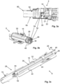
- Figs. 3a - 3e illustrate partial cross sections through portions of a cleaning tool according to embodiments. More specifically, Fig. 3a illustrates a partial cross section through part of a handle portion 4, Figs. 3b - 3d illustrate partial cross sections through a shaft portion 8 and through end portions 26, 28 of the shaft portion 8, and Fig. 3e illustrates a partial cross section through part of a surface cleaning portion 6.
- the cleaning tool may be a cleaning tool 2 as discussed above with reference to Figs. 1a - 2c . Accordingly, in the following reference is also made to Figs. 1a - 2c .
- the cleaning tool comprises a water conduit 22 extending between a water supply coupling element arranged in the handle portion 4 and at least one water outlet nozzle arranged in the surface cleaning portion 6.
- the shaft portion 8 comprises a water channel 24 that forms part of the water conduit 22 and that extends from a first end portion 26 of the shaft portion 8 at the handle portion 4 to a second end portion 28 of the shaft portion 8 at the surface cleaning portion 6.
- the water conduit 22 comprises a portion 21 of the water conduit 22 in the handle portion 4, the water channel 24 comprised in the shaft portion 8, and a portion 23 of the water conduit 22 in the surface cleaning portion 6.
- the shaft portion 8 is removable from the handle portion 4 and from the surface cleaning portion 6, the portion 21 of the water conduit 22 in the handle portion 4 is releasably connected to the water channel 24 and the portion 23 of the water conduit 22 in the surface cleaning portion 6 is releasably connected to the water channel 24.
- the shaft portion 8 comprises a duct 30 through which the driveshaft 16 extends. Within the duct 30, the driveshaft 16 is free to rotate. That is, there is a distance between the driveshaft 16 and inner delimiting surfaces of the duct 30.
- At least part of the shaft portion 8 comprises a tube 32 made from extruded material.
- the tube 32 may be made from aluminium or other extrudable material. That is, the tube 32 is formed in an extrusion process.
- At least part of the water channel 24 and at least part of the duct 30 are formed by the extruded material in one piece as portions of the tube 32. That is, tube 32 forms two inner elongated spaces, one of which forms the duct 30 and the other forming the water channel 24.
- a first water conduit interface 34 between the handle portion 4 and the shaft portion 8 is provided.
- the first water conduit interface 34 comprises a first socket 36 arranged in the shaft portion 8 or in the handle portion 4 and a first protruding tube end portion 38 arranged in the other of the shaft portion 8 and the handle portion 4.
- the first protruding tube end portion 38 fits into the first socket 36.
- the first water conduit interface 34 forms part of the water conduit 22 and provides a releasable connection between the water channel 24 at the first end portion 26 of the shaft portion 8 and the portion 21 of the water conduit 22 in the handle portion 4.
- the first water conduit interface 34 comprises the first socket 36 arranged in the shaft portion 8 and the first protruding tube end portion 38 arranged in the handle portion 4.
- a portion of the water channel 24 may form a portion of the first socket 36 and the first protruding end portion 38 may form part of the portion 21 of the water conduit 22 in the handle portion 4.
- a second water conduit interface 40 between the shaft portion 8 and the surface cleaning portion 6 is provided.
- the second water conduit interface 40 comprises a second socket 42 arranged in the shaft portion 8 or in the surface cleaning portion 6 and a second protruding tube end portion 44 arranged in the other of the shaft portion 8 and the surface cleaning portion 6.
- the second protruding tube end portion 44 fits into the second socket 42.
- the second water conduit interface 40 forms part of the water conduit 22 and provides a releasable connection between the water channel 24 at the second end portion 28 of the shaft portion 8 and the portion 23 of the water conduit 22 in the surface cleaning portion 6.
- the second water conduit interface 40 comprises the second socket 42 arranged in the surface cleaning portion 6 and the second protruding tube end portion 44 arranged in the shaft portion 8.
- a portion of the water channel 24 may extend through the second protruding tube end portion 44 and the second socket 42 may form part of the portion 23 of the water conduit 22 in the surface cleaning portion 6.
- the first protruding tube end portion 38 may be of the same kind as the second protruding tube end portion 44 and the first socket 36 may be of the same kind as the second socket 42.
- the first protruding tube end portion 38 fits into the second socket 42 or the second protruding tube end portion 44 fits into the first socket 36 when the shaft portion 8 is removed from the cleaning tool.
- the cleaning tool may be used with the surface cleaning portion 6 connected directly to the handle portion 4.
- a shorter cleaning tool thus, may be provided and which may be utilised for cleaning tasks where the user of the cleaning tool may want to closely observe the rotatable brush and the surface to be cleaned.
- the driveshaft 16 is journalled within the cleaning tool in order to ensure a vibration free rotation or at least a low vibration rotation of the driveshaft 16 and/or a reliable rotation of the rotatable brush 10.
- One or more bearings may be provided for journaling the driveshaft 16. Such bearings may be arranged in one or more of the handle portion 4, the shaft portion 8, and the surface cleaning portion 6. Such bearings may comprise e.g., one or more plain bearings or ball bearings.
- the shaft portion 8 at its first end portion 26 comprises a first bearing 46 for the driveshaft 16.
- the first bearing 46 and either at least part of the first socket 36 or the first protruding tube end portion 38 are formed in one single first element 48 and the first element 48 being at least partially inserted into the tube 32 made from extruded material at the first end portion 26 of the shaft portion 8. In this manner, journaling of the driveshaft 16 and part of the first water conduit interface 34 are efficiently provided.
- the first element 48 comprises the first socket 36 or the first protruding tube end portion 38.
- the shaft portion 8 at its second end portion 28 comprises a second bearing 50 for the driveshaft 16.
- the second bearing 50 and either at least part of the second socket 42 or the second protruding tube end portion 44 are formed in one single second element 52 and the second element 52 being at least partially inserted into the tube 32 made from extruded material at the second end portion 28 of the shaft portion 8. In this manner, journaling of the driveshaft 16 and part of the second water conduit interface 40 are efficiently provided.
- the second element 52 comprises the second socket 42 or the second protruding tube end portion 44.
- the first element 48 and the second element 52 may be made from a plastic material, such as nylon, PTFE, Polyoxymethylene (POM).
- a plastic material such as nylon, PTFE, Polyoxymethylene (POM).
- the first and second elements 48, 52 may each from part of separate plain bearings.
- the driveshaft 16 may be directly journaled in the first and second elements 48, 52.
- the driveshaft 16 may be indirectly journaled in the first and second elements 48, 52 i.e., further elements may be associated with the driveshaft 16, which further elements are journaled in the first and second elements 48, 52.
- the driveshaft 16 comprises at least three separable portions. One portion of the driveshaft 16 is connected to the electric motor 14. One portion of the driveshaft 16 extends through the shaft portion 8. One portion of the driveshaft 16 extends in the surface cleaning portion 6.
- a first driveshaft interface 54 may be provided for separating the driveshaft 16 between the handle portion 4 and the shaft portion 8.
- a second driveshaft interface 56 may be provided for separating the driveshaft 16 between the shaft portion 8 and the surface cleaning portion 6.
- the cleaning tool 2 comprises a first driveshaft interface 54 between the handle portion 4 and the shaft portion 8.
- the handle portion 4 comprises a hollow end portion 58.
- the first driveshaft interface 54 is recessed from an end 60 of the handle portion 4 within the hollow end portion 58.
- the first end portion 26 of the shaft portion 8 is configured to extend into the hollow end portion 58 of the handle portion 4 for engagement of the first driveshaft interface 54.
- the first end portion 26 of the shaft portion 8 is guided by the hollow end portion 58 of the handle portion 4 when the shaft portion 8 is joined with the handle portion 4.
- the parts of the first driveshaft interface 54 are aligned and a reliable connection is provided between the shaft portion 8 and the handle portion 4.
- the first driveshaft interface 54 forms a separable interface of the driveshaft 16 between a portion of the driveshaft 16 in the handle portion 4 and a portion of the driveshaft 16 in the shaft portion 8.
- one of the portion of the driveshaft 16 in the handle portion 4 and the portion of the driveshaft 16 in the shaft portion 8 may comprise a socket, which is configured for rotationally locked engagement with a protrusion of the other of the portion of the driveshaft 16 in the handle portion 4 and the portion of the driveshaft 16 in the shaft portion 8.
- the cleaning tool 2 comprise a second driveshaft interface 56 between the surface cleaning portion 6 and the shaft portion 8.
- the second driveshaft interface 56 is recessed within the second end portion 28 of the shaft portion 8.
- An end portion 62 of the surface cleaning portion 6 is configured to extend into the second end portion 28 of the shaft portion 8 for engagement of the second driveshaft interface 56.
- the end portion 62 of the surface cleaning portion 6 is guided within the recessed second end portion 28 of the shaft portion 8 when the surface cleaning portion 6 is joined with the shaft portion 8.
- the parts of the second driveshaft interface 56 are aligned and a reliable connection is provided between the shaft portion 8 and the surface cleaning portion 6.
- the second driveshaft interface 56 forms a separable interface of the driveshaft 16 between a portion of the driveshaft 16 in the surface cleaning portion 6 and a portion of the driveshaft 16 in the shaft portion 8.
- one of the portion of the driveshaft 16 in the surface cleaning portion 6 and the portion of the driveshaft 16 in the shaft portion 8 may comprise a socket, which is configured for rotationally locked engagement with a protrusion of the other of the portion of the driveshaft 16 in the surface cleaning portion 6 and the portion of the driveshaft 16 in the shaft portion 8.
- the first driveshaft interface 54 may be of the same kind as the second driveshaft interface 56.
- the surface cleaning portion 6 may be directly connected to the handle portion 4 when the shaft portion 8 is removed from the cleaning tool.
- the cleaning tool 2 is configured for on the one hand to securely and releasably hold the shaft portion 8 to the handle portion 4 and on the other hand to securely and releasably hold the surface cleaning portion 6 to the shaft portion 8.
- the shaft portion 8 is provided with first internal or external threads 64 at its first end portion 26 and the handle portion 4 is provided with external or internal threads 66 configured to mate with the first internal or external threads 64.
- first internal or external threads 64 at its first end portion 26
- handle portion 4 is provided with external or internal threads 66 configured to mate with the first internal or external threads 64.
- the surface engaging portion 6 is provided with second external or internal threads 68 and the shaft portion 8, at its second end portion 28, is provided with internal or external threads 70 configured to mate with the second internal or external threads 68.
- a reliable releasable connection may be provided between the shaft portion 8 and the surface cleaning portion 6.
- the first internal or external threads 64 at the first end portion 26 of the shaft portion 8 may be of the same kind as the second internal or external threads 68 of the surface cleaning portion 6.
- the surface cleaning portion 6 may be directly connected to the handle portion 4 when the shaft portion 8 is removed from the cleaning tool.
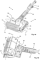
- Figs. 4a and 4b illustrate partial cross sections of a surface cleaning portion 6 according to embodiments.
- the surface cleaning portion 6 is a surface cleaning portion of a cleaning tool such as a cleaning tool 2 as discussed above with reference to Figs. 1a and 2a - 3e. Accordingly, in the following reference is also made to Figs. 1a and 2a - 3e.
- the cleaning tool is configured for supply of water at the surface cleaning portion 6 to be supplied to, or at, the rotatable brush 10, via at least one water outlet nozzle 20.
- the rotatable brush 10 has a rotational axis 12 that extends in parallel with a surface to be cleaned.
- the rotatable brush 10 has a rotational axis 12 extending substantially perpendicularly to the driveshaft 16.
- the rotatable brush 10 comprises a brush roll 72 arranged to engage with a surface to be cleaned tangentially to a rotational direction of the brush roll 72.
- a driveshaft 16 is arranged to transmit a rotation of an electric motor in the handle portion of the cleaning tool for driving/rotating of the rotatable brush 10.
- the surface cleaning portion 6 comprises a transmission 74 arranged between the driveshaft 16 and the rotatable brush 10.
- the rotation of the driveshaft 16 may be transferred to the rotatable brush 10 despite its rotational axis 12 not being aligned with the driveshaft 16.
- the transmission 74 comprises a first portion 76 comprising a bevel gear for transmitting/directing the rotation of the driveshaft 16 perpendicularly to the driveshaft 16 and a second portion 78 comprising a cog belt and two cog wheels.
- the transmission 74 extends laterally of the brush roll 72, i.e., the second portion 78 of the transmission 74, to drive the brush roll 72 from an axial end of the brush roll 72.
- the at least one water outlet nozzle 20 is arranged at a proximity of the rotatable brush 10.
- a water conduit portion 80 in the surface cleaning portion 6 extends past at least a portion of the transmission 74 from a region 82 of the surface cleaning portion 8 positioned at the shaft portion to the at least one water outlet nozzle 20.
- water may be directed through the surface cleaning portion 6 past the transmission 74, such as past the first portion 76 of the transmission 74, to the at least one water outlet nozzle 20.
- the water conduit portion 80 forms part of the portion 23 of the water conduit 22 in the surface cleaning portion 6.
- the bevelled gears of the first portion 76 of the transmission 74 have been omitted to clearly show the water conduit portion 80.
- the surface cleaning portion 8 comprises a splashguard 84 arranged at the rotatable brush 10.
- the at least one water outlet nozzle 20 is arranged on the splashguard 84. In this manner, during use of the cleaning tool, water may be conveniently directed onto the surface to be cleaned close to the rotatable brush 10 and/or onto the rotatable brush 10.
- the splashguard 84 is secured to a housing 86 of the surface cleaning portion 6 laterally of the brush roll 72 and at an axial centre portion of the brush roll 72.
- the splashguard 84 forms a connection between the housing 86 laterally of the brush roll 72 and the housing 86 centrally of the brush roll 72.
- the surface cleaning portion 8 and the brush roll 72 mounted therein are thus, stabilised.
- the splashguard 84 may be secured to the housing 86 via screws 87, see Fig. 4b .
- Figs. 5a and 5b illustrate embodiments of a surface cleaning portion 6 of a cleaning tool.
- Fig. 5a shows a side view of the surface cleaning portion 6
- Fig. 5b show a cross section through the surface cleaning portion 6.
- the cleaning tool may be a cleaning tool 2 as discussed above with reference to Figs. 1 b - 3e. Accordingly, in the following reference is also made to Figs. 1 b - 3e.
- the cleaning tool is configured for supply of water at the surface cleaning portion 6 to be supplied to, or at, the rotatable brush 10, via at least one water outlet nozzle 20.
- the rotatable brush 10 has a rotational axis 12 that extends perpendicularly to a surface to be cleaned.
- the rotatable brush 10 has a rotational axis 12 extending at an angel > 90 degrees to the driveshaft 16.
- the rotatable brush 10 comprises a circular brush 88, an entire surface engaging end 90 of the circular brush 88 is arranged to engage continuously with the surface to be cleaned.
- a driveshaft 16 is arranged to transmit a rotation of an electric motor in the handle portion of the cleaning tool for driving/rotating of the rotatable brush 10.
- the surface cleaning portion 6 comprises a transmission 74 arranged between the driveshaft 16 and the rotatable brush 10.
- the rotation of the driveshaft 16 may be transferred to the rotatable brush 10 despite its rotational axis 12 not being aligned with the driveshaft 16.
- the transmission 74 comprises a bevel gear for transmitting/directing the rotation of the driveshaft 16 to the rotational axis 12 of the rotatable brush 10 at an angle > 90 degrees to the driveshaft 16.
- the at least one water outlet nozzle 20 is arranged at a proximity of the rotatable brush 10. Again, a water conduit portion 80 in the surface cleaning portion 6 extends past at least a portion of the transmission 74 to the at least one water outlet nozzle 20. Thus, during use of the cleaning tool, water may be directed through the surface cleaning portion 6 past the transmission 74 to the at least one water outlet nozzle 20.
- the water conduit portion 80 forms part of and the portion 23 of the water conduit 22 in the surface cleaning portion 6.
- the surface cleaning portion 6 is shown connected to the shaft portion 8. Accordingly, in the cross section of Fig. 5b , the second driveshaft interface 56 is engaged, the second water conduit interface 40 is engaged, and the second external or internal threads 68 of the surface engaging portion 6 are engaged with the internal or external threads 70 at the second end portion 28 of the shaft portion 8.
- the driveshaft interfaces 54, 56, the internal and external threads 64, 66, 68, 70 for connecting the handle portion 4 with the shaft portion 8 and the shaft portion 8 with the surface cleaning portion 6, the transmission 74, the first and second handles 27, 29, the pivotable and lockable second handle 29, the battery 19 may be provided in a cleaning tool that is not specifically devised for wet cleaning. Accordingly, features related to one or more of these aspects may be defined in combination with a cleaning tool that is not limited to features related to wet cleaning, such as e.g., the water conduit, the water outlet nozzle, the water coupling element, etc.
Landscapes
- Cleaning In General (AREA)
Abstract
Description
- The invention relates to a portable handheld cleaning tool.
- Handheld electrically driven cleaning tools are known. Generally, such cleaning tools include a brush rotatable by an electric motor and a handle for a user to grasp and direct the rotatable brush along or over surfaces or objects to be cleaned.
-
CN 206453464 U discloses a motor-driven cleaning brush. The cleaning brush comprises a brush head and a rotatory gear motor for driving a brush arranged at the brush head. A telescopic link including a handle is arranged for adjusting a length of a pole at which the brush head is arranged. -
CN206836552 U discloses a cleaning brush of a similar kind. - It would be advantageous to achieve an improved cleaning tool. According to one aspect, it would be desirable to provide a cleaning tool comprising a rotatable brush being devised for wet cleaning of surfaces. To better address one or more of these concerns, a portable handheld cleaning tool having the features defined in the independent claim is provided.
- According to an aspect of the invention, there is provided a portable handheld cleaning tool comprising a handle portion, a surface cleaning portion, a shaft portion extending between the handle portion and the surface cleaning portion, a rotatable brush arranged in the surface cleaning portion, an electric motor arranged in the handle portion, and a driveshaft extending from the electric motor through the shaft portion to the surface cleaning portion. The shaft portion is removable from the handle portion and from the surface cleaning portion. The cleaning tool is configured for supply of water at the surface cleaning portion and comprises a water supply coupling element arranged at the handle portion, at least one water outlet nozzle arranged in the surface cleaning portion, and a water conduit extending between the water supply coupling element and the at least one water outlet nozzle. The shaft portion comprises a water channel forming part of the water conduit and extending from a first end portion of the shaft portion at the handle portion to a second end portion of the shaft portion at the surface cleaning portion.
- Since the cleaning tool comprises a water supply coupling element arranged at the handle portion, at least one water outlet nozzle arranged in the surface cleaning portion, and a water conduit extending between the water supply coupling element and the at least one water outlet nozzle, and since the shaft portion comprises a water channel forming part of the water conduit and extending from a first end portion of the shaft portion at the handle portion to a second end portion of the shaft portion at the surface cleaning portion - the cleaning tool is devised for wet cleaning.
- Specifically, the cleaning tool is devised for connecting a water supply e.g., via a water hose, to the water supply coupling element at the handle portion and conducting water from the handle portion via the water channel in the shaft portion to the at least one water outlet nozzle in the surface cleaning portion for provision of the water to the surface cleaning portion and/or a surface being cleaned with the cleaning tool. Moreover, this is achieved in a cleaning tool comprising a removable shaft portion.
- Further, due to the water supplying element being provided in the handle portion, during use of the cleaning tool which is configured for wet cleaning, a thereto connected water hose is arranged close to a user of the cleaning tool. The user can thus, easily reach and control the water hose.
- Herein, the portable handheld cleaning tool is alternatively referred to as the cleaning tool. The cleaning tool may be a domestically or commercially utilised cleaning tool.
- The portable handheld cleaning tool is portable and handheld by having a weight such that a user of the cleaning tool firstly, is able to carry the cleaning tool and secondly, handle the cleaning tool as it is being used for cleaning a surface. Optionally, the cleaning tool may be suspended from e.g., a shoulder strap or a harness worn by the user while handling the cleaning tool.
- The handle portion is configured for a user to grasp. The handle portion may comprise one or two or more handles for grasping by a user when handling the cleaning tool.
- The surface cleaning portion is configured for engaging with a surface to be cleaned. The surface to be cleaned may be e.g., a floor surface, a wall surface, etc. The surface to be cleaned may be e.g., an outdoor surface such as a surface of a patio, a driveway, a façade, a planking, etc. The surface to be cleaned may be a surface of an object such as of e.g., a vehicle, a piece of furniture, a garden ornament, a boat, etc.
- The shaft portion extending between the handle portion and the surface cleaning portion may have a length within a range of 0.3 - 3 meters. Since the shaft portion is removable from the handle portion and from the surface cleaning portion, a first shaft portion having a first length may be replaced with a second shaft portion having a second length different from the first length. Accordingly, a suitable length shaft portion may be selected for a particular cleaning task. An alternative may be for the removable shaft portion to comprise a telescopic shaft portion, which is adjustable to a suitable length for a particular cleaning task.
- The rotatable brush that is arranged in the surface cleaning portion is configured for engaging with a surface to be cleaned. The rotatable brush or the entire surface cleaning portion may be exchangeable.
- The rotatable brush may have a rotational axis arranged to extend substantially perpendicularly to a surface to be cleaned or a rotational axis arranged to extend substantially in parallel with a surface to be cleaned.
- The surface cleaning portion may comprise more than one rotatable brush.
- Different surface cleaning portions may comprise rotatable brushes of different kinds. Thus, a suitable surface cleaning portion may be selected from a set of different surface cleaning portions and be connected to the shaft portion for a particular surface cleaning task.
- The electric motor may be powered by a battery arranged in the cleaning tool or carried by a user of the cleaning tool e.g., in a backpack or at a belt around the waist of the user. Alternatively, the electric motor may be powered by mains power via a power cord.
- Since the electric motor is arranged in the handle portion and the driveshaft extends through the shaft portion to the surface cleaning portion, a good weight distribution within the cleaning tool is ensured for holding and handling the cleaning tool e.g., in comparison with prior art cleaning tools having the electric motor arranged close to the rotatable brush. Moreover, a cost-efficient solution is provided for changing between different surface cleaning portions. Namely, since one and the same electric motor arranged in the handle portion can be utilised for driving the rotatable brush of different exchangeable surface cleaning portions, not each surface cleaning portion requires its own electric motor.
- The driveshaft may be journaled in the shaft portion.
- The water supply coupling element may comprise a quick coupling for connecting e.g., a garden hose thereto, also referred to as quick-connect garden hose coupling.
- The at least one water outlet nozzle arranged in the surface cleaning portion may be directed to distribute water over the rotatable brush and/or the surface to be cleaned.
- The water channel comprised in the shaft portion is connectable to a portion of the water conduit in the handle portion and to a portion of the water conduit in the surface cleaning portion. When the handle portion is removed from the shaft portion, the water channel is uncoupled from the portion of the water conduit in the handle portion. When the surface cleaning portion is removed from the shaft portion, the water channel is uncoupled from the portion of the water conduit in the surface cleaning portion.
- According to embodiments, the shaft portion may comprise a duct through which the driveshaft extends, wherein at least part of the shaft portion may comprise a tube made from extruded material, and wherein at least part of the water channel and at least part of the duct are formed by the extruded material in one piece, as portions of the tube. In this manner, a shaft portion that can be cost efficiently manufacture may be provided.
- According to embodiments, the cleaning tool may comprise a first water conduit interface between the handle portion and the shaft portion, wherein the first water conduit interface comprises a first socket arranged in the shaft portion or in the handle portion and a first protruding tube end portion arranged in the other of the shaft portion and the handle portion, and wherein the first protruding tube end portion fits into the first socket. In this manner, there may be provided for the water conduit to be separated when the shaft portion is removed from the handle portion. Namely, the first water conduit interface forms part of the water conduit and provides a releasable connection between the water channel in the shaft portion and the portion of the water conduit in the handle portion.
- According to embodiments, the shaft portion at its first end portion may comprise a first bearing for the driveshaft. In this manner, the driveshaft may be journaled in the shaft portion to ensure reliable rotation of the driveshaft and accordingly, of the rotatable brush during use of the cleaning tool.
- According to embodiments, the cleaning tool may comprise a second water conduit interface between the shaft portion and the surface cleaning portion, wherein the second water conduit interface comprises a second socket arranged in the shaft portion or in the surface cleaning portion and a second protruding tube end portion arranged in the other of the shaft portion and the surface cleaning portion, and wherein the second protruding tube end portion fits into the second socket. In this manner, there may be provided for the water conduit to be separated when the surface cleaning portion is removed from the shaft portion. Namely, the second water conduit interface forms part of the water conduit and provides a releasable connection between a portion of the water conduit in the surface cleaning portion and the water channel in the shaft portion.
- According to embodiments, the shaft portion at its second end portion may comprise a second bearing for the driveshaft. In this manner, the driveshaft may be journaled in the shaft portion to ensure reliable operation of the driveshaft and accordingly, of the rotatable brush during use of the cleaning tool.
- According to embodiments, the surface cleaning portion may comprise a transmission arranged between the driveshaft and the rotatable brush. In this manner, the rotational axis of the rotatable brush may be arranged at an angle to the driveshaft.
- According to embodiments, the at least one water outlet nozzle may be arranged at a proximity of the rotatable brush, wherein a water conduit portion in the surface cleaning portion may extend past at least a portion of the transmission from a region of the surface cleaning portion positioned at the shaft portion to the at least one water outlet nozzle. In this manner, during cleaning, water may be directed to the rotatable brush and/or to the surface to be cleaned at a proximity of the rotatable brush. This may be achieved despite the surface cleaning portion comprising a transmission.
- According to embodiments, the cleaning tool may comprise a flow controlling valve arranged downstream of the water supply coupling element. In this manner, the flow of water to the rotatable brush and/or the surface to be cleaned may be regulated by a user of the cleaning tool.
- According to embodiments, the shaft portion may be provided with first internal or external threads at its first end portion, and the handle portion may be provided with external or internal threads configured to mate with the first internal or external threads. In this manner, a reliable connection may be provided between the shaft portion and the handle portion.
- According to embodiments, the surface engaging portion may be provided with second external or internal threads, and the shaft portion, at its second end portion, may be provided with internal or external threads configured to mate with the second internal or external threads. In this manner, a reliable connection may be provided between the shaft portion and the surface cleaning portion.
- According to embodiments, the cleaning tool may comprise a first driveshaft interface between the handle portion and the shaft portion, wherein the handle portion comprises a hollow end portion, wherein the first driveshaft interface is recessed from an end of the handle portion within the hollow end portion, and wherein the first end portion of the shaft portion is configured to extend into the hollow end portion of the handle portion for engagement of the first driveshaft interface. In this manner, a reliable connection may be provided between the shaft portion and the handle portion.
- According to embodiments, the cleaning tool may comprise a second driveshaft interface between the surface cleaning portion and the shaft portion, wherein the second driveshaft interface is recessed within the second end portion of the shaft portion, and wherein an end portion of the surface cleaning portion is configured to extend into the second end portion of the shaft portion for engagement of the second driveshaft interface. In this manner, a reliable connection may be provided between the shaft portion and the surface cleaning portion.
- According to embodiments, the cleaning tool may comprise a battery arranged to power the electric motor. In this manner, an internal power supply of the cleaning tool may be provided.
- According to embodiments, the rotatable brush may have a rotational axis extending substantially perpendicularly to the driveshaft, and the rotatable brush may comprise a brush roll arranged to engage with a surface to be cleaned tangentially to a rotational direction of the brush roll. In this manner, there may be provided a cleaning tool with a rotatable brush that has a rotational axis configured to extend in parallel with a surface to be cleaned.
- According to embodiments, at least part of the transmission and part of the brush roll may be aligned along an extension of the shaft portion, and wherein the transmission extends laterally of the brush roll to drive the brush roll from an axial end of the brush roll. In this manner, there may be provided a cleaning tool with a transmission configured for driving a rotatable brush that has a rotational axis configured to extend in parallel with a surface to be cleaned.
- According to embodiments, the splashguard may be secured to a housing of the surface cleaning portion laterally of the brush roll and at an axial centre portion of the brush roll. In this manner, the splashguard may be configured for stabilising at least part of the surface cleaning portion comprising a rotatable brush in the form of a brush roll.
- According to embodiments, the rotatable brush may have a rotational axis extending at an angel > 90 degrees to the driveshaft, and the rotatable brush may comprise a circular brush, an entire surface engaging end of the circular brush being arranged to engage continuously with a surface to be cleaned. In this manner, there may be provided a cleaning tool with a rotatable brush having a rotational axis that extends perpendicularly to a surface to be cleaned.
- According to embodiments, the handle portion may comprise a first handle arranged at an end of the cleaning tool and a second handle arranged at an end portion of the handle portion close to the shaft portion. In this manner, the cleaning tool may be configured for a user to precisely control the rotatable brush arranged at the opposite end of the shaft portion.
- According to embodiments, the second handle may be pivotable about a pivot axis and may comprise a locking mechanism configured for releasably locking the second handle in relation to the pivot axis. In this manner, the second handle may be positioned in a manner best suited for a particular cleaning task and/or for the physical constitution of a user of the cleaning tool.
- Again, with an aim of achieving an improved cleaning tool, according to further aspects, it would be desirable to enable a cleaning tool comprising a rotatable brush being devised for one or more of:
- Ensuring a reliable operation of a driveshaft in the shaft portion of the cleaning tool.
- Providing a rotational axis of the rotatable brush that is arranged at an angle to the driveshaft.
- Providing a reliable connection between the shaft portion and the handle portion.
- Providing a reliable connection between the shaft portion and the surface cleaning portion.
- Providing an internal power supply of the cleaning tool.
- Providing a cleaning tool with a rotatable brush that has a rotational axis configured to extend in parallel with a surface to be cleaned.
- Providing a cleaning tool with a rotatable brush that has a rotational axis configured to extend perpendicularly to a surface to be cleaned.
- Providing a cleaning tool that is configured for a user to precisely control the rotatable brush.
- Positioning a second handle of the handle portion in a manner best suited for a particular cleaning task and/or for the physical constitution of a user of the cleaning tool.
- Each of these aspects independently, or in various combinations, may be implemented in a cleaning tool being devised for wet cleaning of surfaces. Alternatively, each of these aspects may be implemented in a cleaning tool that lacks a functionally of wet cleaning.
- Accordingly, each such further aspect may be implemented in a cleaning tool comprising at least the following common denominators: a handle portion, a surface cleaning portion, a shaft portion extending between the handle portion and the surface cleaning portion, a rotatable brush arranged in the surface cleaning portion, an electric motor arranged in the handle portion, and a driveshaft extending from the electric motor through the shaft portion to the surface cleaning portion. According to some embodiments, the shaft portion may be removable from the handle portion and from the surface cleaning portion.
- To better address one or more of these concerns, the portable handheld cleaning tool with these common denominators comprises one or more of the features defined in one or more of the appended dependent claims.
- Further features of, and advantages with, the invention will become apparent when studying the appended claims and the following detailed description.
- Various aspects and/or embodiments of the invention, including its particular features and advantages, will be readily understood from the example embodiments discussed in the following detailed description and the accompanying drawings, in which:
-
Figs. 1a and 1b illustrate embodiments of a portable handheld cleaning tool, -
Figs. 2a - 2c illustrate partial cross sections through portions of a cleaning tool according to embodiments, -
Figs. 3a - 3e illustrate partial cross sections through portions of a cleaning tool according to embodiments, -
Figs. 4a and 4b illustrate partial cross sections of a surface cleaning portion according to embodiments, and -
Figs. 5a and 5b illustrate embodiments of a surface cleaning portion of a cleaning tool. - Aspects and/or embodiments of the invention will now be described more fully. Like numbers refer to like elements throughout. Well-known functions or constructions will not necessarily be described in detail for brevity and/or clarity.
-
Figs. 1a and 1b illustrate embodiments of a portablehandheld cleaning tool 2. In each ofFigs. 1a and 1b thecleaning tool 2 is provided with a different surface cleaning portion, see further below. - The
cleaning tool 2 comprising ahandle portion 4, asurface cleaning portion 6, and ashaft portion 8 extending between thehandle portion 4 and thesurface cleaning portion 6. - A
rotatable brush 10 is arranged in thesurface cleaning portion 6. As can be seen inFigs. 1a and 1b ,surface cleaning portions 8 of different kinds may be provided. Suchsurface cleaning portions 8 of different kinds may be exchangeable. One and thesame handle portion 4 andshaft portion 8 may thus, be provided with differentsurface cleaning portions 6 e.g., depending on what kind of surface is to be cleaned. - As can be seen in
Fig. 1a , according to some embodiments, therotatable brush 10 can have arotational axis 12 that extends in parallel with a surface to be cleaned. As can be seen inFig. 1b , according to some embodiments, therotatable brush 10 can have arotational axis 12 that extends perpendicularly to a surface to be cleaned. - The
cleaning tool 2 is configured for supply of water at thesurface cleaning portion 6. Thecleaning tool 2 is thus, arranged for connection of a water supply, such as a garden hose to the handle portion and for conducting water through theshaft portion 8 and to thesurface cleaning portion 6. At thesurface cleaning portion 6, water is directed to therotatable brush 10 and/or to the surface to be cleaned. See further below inter alia with reference toFigs. 2a - 2c and4a, 4b. - Mentioned purely as an example, the portable
handheld cleaning tool 2 may have a weight within a range of 2 - 15 kg, excluding the weight of a battery. -
Figs. 2a - 2c illustrate partial cross sections through respective of ahandle portion 4, ashaft portion 8, and asurface cleaning portion 6 of a cleaning tool according to embodiments. - The cleaning tool may be a
cleaning tool 2 as discussed above with reference toFigs. 1a and 1b . Accordingly, in the following reference is also made toFigs. 1a and 1b . - An
electric motor 14 is arranged in thehandle portion 6. Adriveshaft 16 extends from theelectric motor 14 through theshaft portion 8 to thesurface cleaning portion 6. - The
shaft portion 8 is removable from thehandle portion 4 and from thesurface cleaning portion 6. Accordingly, thecleaning tool 2 may be taken apart into three separate parts. Each of theshaft portion 8, thehandle portion 4, and thesurface cleaning portion 6 form a separate part. - As mentioned above, the
cleaning tool 2 is configured for supply of water at thesurface cleaning portion 6. Thus, thecleaning tool 2 comprises a watersupply coupling element 18 arranged at thehandle portion 4, at least onewater outlet nozzle 20 arranged in thesurface cleaning portion 6, and awater conduit 22 extending between the watersupply coupling element 18 and the at least onewater outlet nozzle 20. - The
surface cleaning portion 6 in these embodiments comprises twowater outlet nozzles 20. - The
shaft portion 8 comprises awater channel 24 that forms part of thewater conduit 22 and that extends from afirst end portion 26 of theshaft portion 8 at thehandle portion 4 to asecond end portion 28 of theshaft portion 8 at thesurface cleaning portion 6. - In the illustrated embodiments, the
cleaning tool 2 comprises aflow controlling valve 25 arranged downstream of the watersupply coupling element 18. Thus, a user of thecleaning tool 2, at thehandle portion 4, may control the flow of water to therotatable brush 10 and/or to the surface to be cleaned by setting theflow controlling valve 25 at a desired flow setting. - The
cleaning tool 2 may comprise abattery 19 arranged to power theelectric motor 14. - The
battery 19 is schematically indicated in thehandle portion 4. Such abattery 19 is suitably rechargeable. - As an alternative, the
electric motor 14 may be power by mains power via an electric cord. - The
handle portion 4 comprises afirst handle 27 arranged at an end of thecleaning tool 2 and asecond handle 29 arranged at an end portion of thehandle portion 4 close to theshaft portion 8. - A user of the
cleaning tool 2 grasps each of the first andsecond handles cleaning tool 2 and to move therotatable brush 10 over the surface to be cleaned. - In connection with the
first handle 27, user operated control means may be provided, such as a pushbutton for starting and stopping theelectric motor 14. - The
second handle 29 is pivotable about apivot axis 31 and comprises alocking mechanism 33 configured for releasably locking thesecond handle 29 in relation to thepivot axis 31. Thus, thesecond handle 29 may be arranged in one out of at least two different pivotal positions for a user of the cleaning tool to grasp. - The
locking mechanism 33 may be any suitable locking mechanism that securely locks the rotation of thesecond handle 29 in relation to thepivot axis 31. For instance, thelocking mechanism 33 may comprise a fixed cog wheel arranged in a body of thehandle portion 4 and a movable pin arranged at thesecond handle 29, which movable pin is arranged to releasably engage with the cogs of the fixed cog wheel. -
Figs. 3a - 3e illustrate partial cross sections through portions of a cleaning tool according to embodiments. More specifically,Fig. 3a illustrates a partial cross section through part of ahandle portion 4,Figs. 3b - 3d illustrate partial cross sections through ashaft portion 8 and throughend portions shaft portion 8, andFig. 3e illustrates a partial cross section through part of asurface cleaning portion 6. - The cleaning tool may be a
cleaning tool 2 as discussed above with reference toFigs. 1a - 2c . Accordingly, in the following reference is also made toFigs. 1a - 2c . - Again, the cleaning tool comprises a
water conduit 22 extending between a water supply coupling element arranged in thehandle portion 4 and at least one water outlet nozzle arranged in thesurface cleaning portion 6. Theshaft portion 8 comprises awater channel 24 that forms part of thewater conduit 22 and that extends from afirst end portion 26 of theshaft portion 8 at thehandle portion 4 to asecond end portion 28 of theshaft portion 8 at thesurface cleaning portion 6. - Accordingly, the
water conduit 22 comprises aportion 21 of thewater conduit 22 in thehandle portion 4, thewater channel 24 comprised in theshaft portion 8, and aportion 23 of thewater conduit 22 in thesurface cleaning portion 6. - Since the
shaft portion 8 is removable from thehandle portion 4 and from thesurface cleaning portion 6, theportion 21 of thewater conduit 22 in thehandle portion 4 is releasably connected to thewater channel 24 and theportion 23 of thewater conduit 22 in thesurface cleaning portion 6 is releasably connected to thewater channel 24. - The
shaft portion 8 comprises aduct 30 through which thedriveshaft 16 extends. Within theduct 30, thedriveshaft 16 is free to rotate. That is, there is a distance between thedriveshaft 16 and inner delimiting surfaces of theduct 30. - At least part of the
shaft portion 8 comprises atube 32 made from extruded material. For instance, thetube 32 may be made from aluminium or other extrudable material. That is, thetube 32 is formed in an extrusion process. - At least part of the
water channel 24 and at least part of theduct 30 are formed by the extruded material in one piece as portions of thetube 32. That is,tube 32 forms two inner elongated spaces, one of which forms theduct 30 and the other forming thewater channel 24. - A first
water conduit interface 34 between thehandle portion 4 and theshaft portion 8 is provided. The firstwater conduit interface 34 comprises afirst socket 36 arranged in theshaft portion 8 or in thehandle portion 4 and a first protrudingtube end portion 38 arranged in the other of theshaft portion 8 and thehandle portion 4. The first protrudingtube end portion 38 fits into thefirst socket 36. - The first
water conduit interface 34 forms part of thewater conduit 22 and provides a releasable connection between thewater channel 24 at thefirst end portion 26 of theshaft portion 8 and theportion 21 of thewater conduit 22 in thehandle portion 4. - In the illustrated embodiments, the first
water conduit interface 34 comprises thefirst socket 36 arranged in theshaft portion 8 and the first protrudingtube end portion 38 arranged in thehandle portion 4. For instance, a portion of thewater channel 24 may form a portion of thefirst socket 36 and the firstprotruding end portion 38 may form part of theportion 21 of thewater conduit 22 in thehandle portion 4. - A second
water conduit interface 40 between theshaft portion 8 and thesurface cleaning portion 6 is provided. The secondwater conduit interface 40 comprises asecond socket 42 arranged in theshaft portion 8 or in thesurface cleaning portion 6 and a second protrudingtube end portion 44 arranged in the other of theshaft portion 8 and thesurface cleaning portion 6. The second protrudingtube end portion 44 fits into thesecond socket 42. - The second
water conduit interface 40 forms part of thewater conduit 22 and provides a releasable connection between thewater channel 24 at thesecond end portion 28 of theshaft portion 8 and theportion 23 of thewater conduit 22 in thesurface cleaning portion 6. - In the illustrated embodiments, the second
water conduit interface 40 comprises thesecond socket 42 arranged in thesurface cleaning portion 6 and the second protrudingtube end portion 44 arranged in theshaft portion 8. For instance, a portion of thewater channel 24 may extend through the second protrudingtube end portion 44 and thesecond socket 42 may form part of theportion 23 of thewater conduit 22 in thesurface cleaning portion 6. - According to some embodiments, the first protruding
tube end portion 38 may be of the same kind as the second protrudingtube end portion 44 and thefirst socket 36 may be of the same kind as thesecond socket 42. - According to such embodiments, the first protruding
tube end portion 38 fits into thesecond socket 42 or the second protrudingtube end portion 44 fits into thefirst socket 36 when theshaft portion 8 is removed from the cleaning tool. In this manner, the cleaning tool may be used with thesurface cleaning portion 6 connected directly to thehandle portion 4. A shorter cleaning tool thus, may be provided and which may be utilised for cleaning tasks where the user of the cleaning tool may want to closely observe the rotatable brush and the surface to be cleaned. - The
driveshaft 16 is journalled within the cleaning tool in order to ensure a vibration free rotation or at least a low vibration rotation of thedriveshaft 16 and/or a reliable rotation of therotatable brush 10. One or more bearings may be provided for journaling thedriveshaft 16. Such bearings may be arranged in one or more of thehandle portion 4, theshaft portion 8, and thesurface cleaning portion 6. Such bearings may comprise e.g., one or more plain bearings or ball bearings. - According to some embodiments, such as the illustrated embodiments, the
shaft portion 8 at itsfirst end portion 26 comprises afirst bearing 46 for thedriveshaft 16. - According to embodiments, the
first bearing 46 and either at least part of thefirst socket 36 or the first protrudingtube end portion 38 are formed in one singlefirst element 48 and thefirst element 48 being at least partially inserted into thetube 32 made from extruded material at thefirst end portion 26 of theshaft portion 8. In this manner, journaling of thedriveshaft 16 and part of the firstwater conduit interface 34 are efficiently provided. - More specifically, depending on whether the
first end portion 26 of theshaft portion 8 comprises thefirst socket 36 or the first protrudingtube end portion 38, thefirst element 48 comprises thefirst socket 36 or the first protrudingtube end portion 38. - According to some embodiments, such as the illustrated embodiments, the
shaft portion 8 at itssecond end portion 28 comprises asecond bearing 50 for thedriveshaft 16. - According to embodiments, the
second bearing 50 and either at least part of thesecond socket 42 or the second protrudingtube end portion 44 are formed in one singlesecond element 52 and thesecond element 52 being at least partially inserted into thetube 32 made from extruded material at thesecond end portion 28 of theshaft portion 8. In this manner, journaling of thedriveshaft 16 and part of the secondwater conduit interface 40 are efficiently provided. - Depending on whether the
second end portion 28 of theshaft portion 8 comprises thesecond socket 42 or the second protrudingtube end portion 44, thesecond element 52 comprises thesecond socket 42 or the second protrudingtube end portion 44. - The
first element 48 and thesecond element 52 may be made from a plastic material, such as nylon, PTFE, Polyoxymethylene (POM). - The first and
second elements driveshaft 16 may be directly journaled in the first andsecond elements driveshaft 16 may be indirectly journaled in the first andsecond elements driveshaft 16, which further elements are journaled in the first andsecond elements - Since the
shaft portion 8 is removable from thehandle portion 4 and from thesurface cleaning portion 6, thedriveshaft 16 comprises at least three separable portions. One portion of thedriveshaft 16 is connected to theelectric motor 14. One portion of thedriveshaft 16 extends through theshaft portion 8. One portion of thedriveshaft 16 extends in thesurface cleaning portion 6. - A
first driveshaft interface 54 may be provided for separating thedriveshaft 16 between thehandle portion 4 and theshaft portion 8. Asecond driveshaft interface 56 may be provided for separating thedriveshaft 16 between theshaft portion 8 and thesurface cleaning portion 6. - The
cleaning tool 2 comprises afirst driveshaft interface 54 between thehandle portion 4 and theshaft portion 8. Thehandle portion 4 comprises ahollow end portion 58. Thefirst driveshaft interface 54 is recessed from anend 60 of thehandle portion 4 within thehollow end portion 58. Thefirst end portion 26 of theshaft portion 8 is configured to extend into thehollow end portion 58 of thehandle portion 4 for engagement of thefirst driveshaft interface 54. Thus, thefirst end portion 26 of theshaft portion 8 is guided by thehollow end portion 58 of thehandle portion 4 when theshaft portion 8 is joined with thehandle portion 4. Thus, the parts of thefirst driveshaft interface 54 are aligned and a reliable connection is provided between theshaft portion 8 and thehandle portion 4. - The
first driveshaft interface 54 forms a separable interface of thedriveshaft 16 between a portion of thedriveshaft 16 in thehandle portion 4 and a portion of thedriveshaft 16 in theshaft portion 8. For instance, one of the portion of thedriveshaft 16 in thehandle portion 4 and the portion of thedriveshaft 16 in theshaft portion 8 may comprise a socket, which is configured for rotationally locked engagement with a protrusion of the other of the portion of thedriveshaft 16 in thehandle portion 4 and the portion of thedriveshaft 16 in theshaft portion 8. - The
cleaning tool 2 comprise asecond driveshaft interface 56 between thesurface cleaning portion 6 and theshaft portion 8. Thesecond driveshaft interface 56 is recessed within thesecond end portion 28 of theshaft portion 8. Anend portion 62 of thesurface cleaning portion 6 is configured to extend into thesecond end portion 28 of theshaft portion 8 for engagement of thesecond driveshaft interface 56. Thus, theend portion 62 of thesurface cleaning portion 6 is guided within the recessedsecond end portion 28 of theshaft portion 8 when thesurface cleaning portion 6 is joined with theshaft portion 8. Thus, the parts of thesecond driveshaft interface 56 are aligned and a reliable connection is provided between theshaft portion 8 and thesurface cleaning portion 6. - The
second driveshaft interface 56 forms a separable interface of thedriveshaft 16 between a portion of thedriveshaft 16 in thesurface cleaning portion 6 and a portion of thedriveshaft 16 in theshaft portion 8. For instance, one of the portion of thedriveshaft 16 in thesurface cleaning portion 6 and the portion of thedriveshaft 16 in theshaft portion 8 may comprise a socket, which is configured for rotationally locked engagement with a protrusion of the other of the portion of thedriveshaft 16 in thesurface cleaning portion 6 and the portion of thedriveshaft 16 in theshaft portion 8. - According to some embodiments, the
first driveshaft interface 54 may be of the same kind as thesecond driveshaft interface 56. Thus, thesurface cleaning portion 6 may be directly connected to thehandle portion 4 when theshaft portion 8 is removed from the cleaning tool. - The
cleaning tool 2 is configured for on the one hand to securely and releasably hold theshaft portion 8 to thehandle portion 4 and on the other hand to securely and releasably hold thesurface cleaning portion 6 to theshaft portion 8. - According to some embodiments, such as the illustrated embodiments, the
shaft portion 8 is provided with first internal orexternal threads 64 at itsfirst end portion 26 and thehandle portion 4 is provided with external orinternal threads 66 configured to mate with the first internal orexternal threads 64. Thus, a reliable releasable connection may be provided between theshaft portion 8 and thehandle portion 4. - According to embodiments, such as the illustrated embodiments, the
surface engaging portion 6 is provided with second external orinternal threads 68 and theshaft portion 8, at itssecond end portion 28, is provided with internal orexternal threads 70 configured to mate with the second internal orexternal threads 68. Thus, a reliable releasable connection may be provided between theshaft portion 8 and thesurface cleaning portion 6. - According to some embodiments, the first internal or
external threads 64 at thefirst end portion 26 of theshaft portion 8 may be of the same kind as the second internal orexternal threads 68 of thesurface cleaning portion 6. Thus, thesurface cleaning portion 6 may be directly connected to thehandle portion 4 when theshaft portion 8 is removed from the cleaning tool. -
Figs. 4a and 4b illustrate partial cross sections of asurface cleaning portion 6 according to embodiments. Thesurface cleaning portion 6 is a surface cleaning portion of a cleaning tool such as acleaning tool 2 as discussed above with reference toFigs. 1a and2a - 3e. Accordingly, in the following reference is also made toFigs. 1a and2a - 3e. - Again, the cleaning tool is configured for supply of water at the
surface cleaning portion 6 to be supplied to, or at, therotatable brush 10, via at least onewater outlet nozzle 20. In these embodiments, therotatable brush 10 has arotational axis 12 that extends in parallel with a surface to be cleaned. - Accordingly, the
rotatable brush 10 has arotational axis 12 extending substantially perpendicularly to thedriveshaft 16. Therotatable brush 10 comprises abrush roll 72 arranged to engage with a surface to be cleaned tangentially to a rotational direction of thebrush roll 72. - Again, a
driveshaft 16 is arranged to transmit a rotation of an electric motor in the handle portion of the cleaning tool for driving/rotating of therotatable brush 10. - The
surface cleaning portion 6 comprises atransmission 74 arranged between thedriveshaft 16 and therotatable brush 10. Thus, the rotation of thedriveshaft 16 may be transferred to therotatable brush 10 despite itsrotational axis 12 not being aligned with thedriveshaft 16. - In these embodiments, the
transmission 74 comprises afirst portion 76 comprising a bevel gear for transmitting/directing the rotation of thedriveshaft 16 perpendicularly to thedriveshaft 16 and asecond portion 78 comprising a cog belt and two cog wheels. - Accordingly, at least part of the transmission, such as the
first portion 76 of thetransmission 74 and part of thebrush roll 72 are aligned along an extension of the shaft portion i.e., along an extension of thedriveshaft 16. Moreover, thetransmission 74 extends laterally of thebrush roll 72, i.e., thesecond portion 78 of thetransmission 74, to drive thebrush roll 72 from an axial end of thebrush roll 72. - The at least one
water outlet nozzle 20 is arranged at a proximity of therotatable brush 10. Awater conduit portion 80 in thesurface cleaning portion 6 extends past at least a portion of thetransmission 74 from aregion 82 of thesurface cleaning portion 8 positioned at the shaft portion to the at least onewater outlet nozzle 20. Thus, during use of the cleaning tool, water may be directed through thesurface cleaning portion 6 past thetransmission 74, such as past thefirst portion 76 of thetransmission 74, to the at least onewater outlet nozzle 20. - The
water conduit portion 80 forms part of theportion 23 of thewater conduit 22 in thesurface cleaning portion 6. InFig. 4b , the bevelled gears of thefirst portion 76 of thetransmission 74 have been omitted to clearly show thewater conduit portion 80. - According to some embodiments, such as the illustrated embodiments, the
surface cleaning portion 8 comprises asplashguard 84 arranged at therotatable brush 10. The at least onewater outlet nozzle 20 is arranged on thesplashguard 84. In this manner, during use of the cleaning tool, water may be conveniently directed onto the surface to be cleaned close to therotatable brush 10 and/or onto therotatable brush 10. - According to some embodiments, such as the illustrated embodiments, the
splashguard 84 is secured to ahousing 86 of thesurface cleaning portion 6 laterally of thebrush roll 72 and at an axial centre portion of thebrush roll 72. Thus, thesplashguard 84 forms a connection between thehousing 86 laterally of thebrush roll 72 and thehousing 86 centrally of thebrush roll 72. Thesurface cleaning portion 8 and thebrush roll 72 mounted therein are thus, stabilised. - For instance, the
splashguard 84 may be secured to thehousing 86 viascrews 87, seeFig. 4b . -
Figs. 5a and 5b illustrate embodiments of asurface cleaning portion 6 of a cleaning tool.Fig. 5a shows a side view of thesurface cleaning portion 6 andFig. 5b show a cross section through thesurface cleaning portion 6. The cleaning tool may be acleaning tool 2 as discussed above with reference toFigs. 1 b - 3e. Accordingly, in the following reference is also made toFigs. 1 b - 3e. - Again, the cleaning tool is configured for supply of water at the
surface cleaning portion 6 to be supplied to, or at, therotatable brush 10, via at least onewater outlet nozzle 20. In these embodiments, therotatable brush 10 has arotational axis 12 that extends perpendicularly to a surface to be cleaned. - Accordingly, the
rotatable brush 10 has arotational axis 12 extending at an angel > 90 degrees to thedriveshaft 16. Therotatable brush 10 comprises acircular brush 88, an entiresurface engaging end 90 of thecircular brush 88 is arranged to engage continuously with the surface to be cleaned. - Again, a
driveshaft 16 is arranged to transmit a rotation of an electric motor in the handle portion of the cleaning tool for driving/rotating of therotatable brush 10. - The
surface cleaning portion 6 comprises atransmission 74 arranged between thedriveshaft 16 and therotatable brush 10. Thus, the rotation of thedriveshaft 16 may be transferred to therotatable brush 10 despite itsrotational axis 12 not being aligned with thedriveshaft 16. - In these embodiments, the
transmission 74 comprises a bevel gear for transmitting/directing the rotation of thedriveshaft 16 to therotational axis 12 of therotatable brush 10 at an angle > 90 degrees to thedriveshaft 16. - The at least one
water outlet nozzle 20 is arranged at a proximity of therotatable brush 10. Again, awater conduit portion 80 in thesurface cleaning portion 6 extends past at least a portion of thetransmission 74 to the at least onewater outlet nozzle 20. Thus, during use of the cleaning tool, water may be directed through thesurface cleaning portion 6 past thetransmission 74 to the at least onewater outlet nozzle 20. - The
water conduit portion 80 forms part of and theportion 23 of thewater conduit 22 in thesurface cleaning portion 6. - Generally, in
Figs. 5a and 5b , thesurface cleaning portion 6 is shown connected to theshaft portion 8. Accordingly, in the cross section ofFig. 5b , thesecond driveshaft interface 56 is engaged, the secondwater conduit interface 40 is engaged, and the second external orinternal threads 68 of thesurface engaging portion 6 are engaged with the internal orexternal threads 70 at thesecond end portion 28 of theshaft portion 8. - It is to be understood that the foregoing is illustrative of various example embodiments and that the invention is defined only by the appended claims. A person skilled in the art will realize that the example embodiments may be modified, and that different features of the example embodiments may be combined to create embodiments other than those described herein, without departing from the scope of the invention, as defined by the appended claims. For instance, the driveshaft interfaces 54, 56, the internal and
external threads handle portion 4 with theshaft portion 8 and theshaft portion 8 with thesurface cleaning portion 6, thetransmission 74, the first andsecond handles second handle 29, thebattery 19 may be provided in a cleaning tool that is not specifically devised for wet cleaning. Accordingly, features related to one or more of these aspects may be defined in combination with a cleaning tool that is not limited to features related to wet cleaning, such as e.g., the water conduit, the water outlet nozzle, the water coupling element, etc.
Claims (15)
- A portable handheld cleaning tool (2) comprising a handle portion (4), a surface cleaning portion (6), a shaft portion (8) extending between the handle portion (4) and the surface cleaning portion (6), a rotatable brush (10) arranged in the surface cleaning portion (6), an electric motor (14) arranged in the handle portion (4), and a driveshaft (16) extending from the electric motor (14) through the shaft portion (8) to the surface cleaning portion (6), whereinthe shaft portion (8) is removable from the handle portion (4) and from the surface cleaning portion (6), whereinthe cleaning tool (2) is configured for supply of water at the surface cleaning portion (6) and comprises a water supply coupling element (18) arranged at the handle portion (4), at least one water outlet nozzle (20) arranged in the surface cleaning portion (6), and a water conduit (22) extending between the water supply coupling element (18) and the at least one water outlet nozzle (20), and whereinthe shaft portion (8) comprises a water channel (24), forming part of the water conduit (22) and extending from a first end portion (26) of the shaft portion (8) at the handle portion (4) to a second end portion (28) of the shaft portion (8) at the surface cleaning portion (6).
- The cleaning tool (2) according to claim 1, wherein the shaft portion (8) comprises a duct (30) through which the driveshaft (16) extends, wherein at least part of the shaft portion (8) comprises a tube (32) made from extruded material, and wherein at least part of the water channel (24) and at least part of the duct (30) are formed by the extruded material in one piece as portions of the tube (32).
- The cleaning tool (2) according to claim 1 or 2, comprising a first water conduit interface (34) between the handle portion (4) and the shaft portion (8), wherein the first water conduit interface (34) comprises a first socket (36) arranged in the shaft portion (8) or in the handle portion (4) and a first protruding tube end portion (38) arranged in the other of the shaft portion (8) and the handle portion (4), and wherein the first protruding tube end portion (38) fits into the first socket (36).
- The cleaning tool (2) according to any one of the preceding claims, wherein the shaft portion (8) at its first end portion (26) comprises a first bearing (46) for the driveshaft (16).
- The cleaning tool (2) according to claims 2 - 4, wherein the first bearing (46) and either at least part of the first socket (36) or the first protruding tube end portion (38) are formed in one single first element (48) and the first element (48) being at least partially inserted into the tube (32) made from extruded material at the first end portion (26) of the shaft portion (8).
- The cleaning tool (2) according to any one of the preceding claims, comprising a second water conduit interface (40) between the shaft portion (8) and the surface cleaning portion (6), wherein the second water conduit interface (40) comprises a second socket (42) arranged in the shaft portion (8) or in the surface cleaning portion (6) and a second protruding tube end portion (44) arranged in the other of the shaft portion (8) and the surface cleaning portion (6), and wherein the second protruding tube end portion (44) fits into the second socket (42).
- The cleaning tool (2) according to claim 6 and any one of claim 3 or 5, wherein the first protruding tube end portion (38) fits into the second socket (42) or the second protruding tube end portion (44) fits into the first socket (36) when the shaft portion (8) is removed from the cleaning tool (2).
- The cleaning tool (2) according to any one of the preceding claims, wherein the shaft portion (8) at its second end portion (28) comprises a second bearing (50) for the driveshaft (16).
- The cleaning tool (2) according to claims 2 and 6 and 8, wherein the second bearing (50) and either at least part of the second socket (42) or the second protruding tube end portion (44) are formed in one single second element (52) and the second element (52) being at least partially inserted into the tube (32) made from extruded material at the second end portion (28) of the shaft portion (8).
- The cleaning tool (2) according to any one of the preceding claims, wherein the surface cleaning portion (6) comprises a transmission (74) arranged between the driveshaft (16) and the rotatable brush (10).
- The cleaning tool (2) according to claim 10, wherein the at least one water outlet nozzle (20) is arranged at a proximity of the rotatable brush (10), and wherein a water conduit portion (80) in the surface cleaning portion (6) extends past at least a portion of the transmission from a region (82) of the surface cleaning portion (6) positioned at the shaft portion (8) to the at least one water outlet nozzle (20).
- The cleaning tool (2) according to any one of the preceding claims, wherein the surface cleaning portion (6) comprises a splashguard (84) arranged at the rotatable brush (10), and wherein the at least one water outlet nozzle (20) is arranged on the splashguard (84).
- The cleaning tool (2) according to any one of the preceding claims, comprising a flow controlling valve (25) arranged downstream of the water supply coupling element (18).
- The cleaning tool (2) according to any one of the preceding claims, comprising a first driveshaft interface (54) between the handle portion (4) and the shaft portion (8), wherein the handle portion (4) comprises a hollow end portion (58), wherein the first driveshaft interface (54) is recessed from an end (60) of the handle portion (4) within the hollow end portion (58), and wherein the first end portion (26) of the shaft portion (8) is configured to extend into the hollow end portion (58) of the handle portion (4) for engagement of the first driveshaft interface (54).
- The cleaning tool (2) according to any one of the preceding claims, comprising a second driveshaft interface (56) between the surface cleaning portion (6) and the shaft portion (8), wherein the second driveshaft interface (56) is recessed within the second end portion (28) of the shaft portion (8), and wherein an end portion (62) of the surface cleaning portion (6) is configured to extend into the second end portion (28) of the shaft portion (8) for engagement of the second driveshaft interface (56).
Priority Applications (2)
| Application Number | Priority Date | Filing Date | Title |
|---|---|---|---|
| EP23159175.1A EP4424222B1 (en) | 2023-02-28 | 2023-02-28 | Portable handheld cleaning tool |
| CN202410216321.9A CN118556981A (en) | 2023-02-28 | 2024-02-27 | Portable Handheld Cleaning Tools |
Applications Claiming Priority (1)
| Application Number | Priority Date | Filing Date | Title |
|---|---|---|---|
| EP23159175.1A EP4424222B1 (en) | 2023-02-28 | 2023-02-28 | Portable handheld cleaning tool |
Publications (2)
| Publication Number | Publication Date |
|---|---|
| EP4424222A1 true EP4424222A1 (en) | 2024-09-04 |
| EP4424222B1 EP4424222B1 (en) | 2025-10-22 |
Family
ID=85410369
Family Applications (1)
| Application Number | Title | Priority Date | Filing Date |
|---|---|---|---|
| EP23159175.1A Active EP4424222B1 (en) | 2023-02-28 | 2023-02-28 | Portable handheld cleaning tool |
Country Status (2)
| Country | Link |
|---|---|
| EP (1) | EP4424222B1 (en) |
| CN (1) | CN118556981A (en) |
Citations (9)
| Publication number | Priority date | Publication date | Assignee | Title |
|---|---|---|---|---|
| US4335481A (en) * | 1980-04-17 | 1982-06-22 | Slayman Glen E | Motor driven washing, polishing wand |
| US4780992A (en) * | 1987-05-04 | 1988-11-01 | Mckervey Roy B | Apparatus for cleaning pool tile |
| US5146642A (en) * | 1991-05-28 | 1992-09-15 | The United States Of America As Represented By The Secretary Of The Army | Powered scrub brush |
| KR100787144B1 (en) * | 2007-01-08 | 2007-12-21 | 김문정 | vacuum cleaner |
| EP1961518A1 (en) * | 2007-02-22 | 2008-08-27 | Flex-Elektrowerkzeuge GmbH | Handheld clearing/grinding machine |
| CN206453464U (en) | 2017-01-26 | 2017-09-01 | 宁波博高国际贸易有限公司 | A kind of electric cleaning brush |
| CN206836552U (en) | 2017-04-13 | 2018-01-05 | 宁波博高国际贸易有限公司 | A kind of electric cleaning brush |
| CN112386182A (en) * | 2020-12-08 | 2021-02-23 | 江苏苏美达五金工具有限公司 | Floor brush and water-cooling waterproof motor |
| DE202022100665U1 (en) * | 2021-12-21 | 2022-02-18 | Shouqiang Mi | multifunction brush |
Family Cites Families (1)
| Publication number | Priority date | Publication date | Assignee | Title |
|---|---|---|---|---|
| WO2007063452A2 (en) * | 2005-11-30 | 2007-06-07 | John Turner | Scavenging cleaning system |
-
2023
- 2023-02-28 EP EP23159175.1A patent/EP4424222B1/en active Active
-
2024
- 2024-02-27 CN CN202410216321.9A patent/CN118556981A/en active Pending
Patent Citations (9)
| Publication number | Priority date | Publication date | Assignee | Title |
|---|---|---|---|---|
| US4335481A (en) * | 1980-04-17 | 1982-06-22 | Slayman Glen E | Motor driven washing, polishing wand |
| US4780992A (en) * | 1987-05-04 | 1988-11-01 | Mckervey Roy B | Apparatus for cleaning pool tile |
| US5146642A (en) * | 1991-05-28 | 1992-09-15 | The United States Of America As Represented By The Secretary Of The Army | Powered scrub brush |
| KR100787144B1 (en) * | 2007-01-08 | 2007-12-21 | 김문정 | vacuum cleaner |
| EP1961518A1 (en) * | 2007-02-22 | 2008-08-27 | Flex-Elektrowerkzeuge GmbH | Handheld clearing/grinding machine |
| CN206453464U (en) | 2017-01-26 | 2017-09-01 | 宁波博高国际贸易有限公司 | A kind of electric cleaning brush |
| CN206836552U (en) | 2017-04-13 | 2018-01-05 | 宁波博高国际贸易有限公司 | A kind of electric cleaning brush |
| CN112386182A (en) * | 2020-12-08 | 2021-02-23 | 江苏苏美达五金工具有限公司 | Floor brush and water-cooling waterproof motor |
| DE202022100665U1 (en) * | 2021-12-21 | 2022-02-18 | Shouqiang Mi | multifunction brush |
Also Published As
| Publication number | Publication date |
|---|---|
| CN118556981A (en) | 2024-08-30 |
| EP4424222B1 (en) | 2025-10-22 |
Similar Documents
| Publication | Publication Date | Title |
|---|---|---|
| US20080201877A1 (en) | Hand-held cleaning/polishing machine | |
| US4335481A (en) | Motor driven washing, polishing wand | |
| US5809601A (en) | Device for cleaning the interior of a tubular member | |
| US7314096B2 (en) | Adjustable handle for portable tool | |
| US5885145A (en) | Powered drywall sander and painter | |
| US8757925B2 (en) | Cordless concrete finishing tool | |
| CN103702649B (en) | Gentle skin-treatment device | |
| US4347450A (en) | Portable power tool | |
| US7382104B2 (en) | Backpack style power-pack with flexible drive and quick connect power take-off for connection to a variety of powered tools | |
| US20090065607A1 (en) | Pressure washer system | |
| US5056265A (en) | Tube end abrading tool | |
| US7677281B2 (en) | Power router tool | |
| US8480457B2 (en) | Surface preparation apparatus | |
| US9380859B2 (en) | Cleaning apparatus | |
| US20120285485A1 (en) | Cleaning apparatus | |
| US8277292B2 (en) | Inline handheld power tool | |
| US5603435A (en) | Repainting gun | |
| CN102245935A (en) | Rotary units, rotary mechanisms and related applications | |
| CN110052934A (en) | Cutter and cutter grinding machine | |
| EP4424222B1 (en) | Portable handheld cleaning tool | |
| US5947806A (en) | Power sander | |
| KR101025630B1 (en) | Shell debris removal device | |
| US4254526A (en) | Car washing aid | |
| US20230059781A1 (en) | Outdoor surface cleaning apparatus with spray mechanism | |
| EP4101361B1 (en) | Fluid dispensing scrubber |
Legal Events
| Date | Code | Title | Description |
|---|---|---|---|
| PUAI | Public reference made under article 153(3) epc to a published international application that has entered the european phase |
Free format text: ORIGINAL CODE: 0009012 |
|
| STAA | Information on the status of an ep patent application or granted ep patent |
Free format text: STATUS: REQUEST FOR EXAMINATION WAS MADE |
|
| 17P | Request for examination filed |
Effective date: 20240124 |
|
| AK | Designated contracting states |
Kind code of ref document: A1 Designated state(s): AL AT BE BG CH CY CZ DE DK EE ES FI FR GB GR HR HU IE IS IT LI LT LU LV MC ME MK MT NL NO PL PT RO RS SE SI SK SM TR |
|
| GRAP | Despatch of communication of intention to grant a patent |
Free format text: ORIGINAL CODE: EPIDOSNIGR1 |
|
| STAA | Information on the status of an ep patent application or granted ep patent |
Free format text: STATUS: GRANT OF PATENT IS INTENDED |
|
| RIC1 | Information provided on ipc code assigned before grant |
Ipc: A47L 11/282 20060101AFI20250625BHEP Ipc: A47L 11/40 20060101ALI20250625BHEP Ipc: B08B 3/02 20060101ALI20250625BHEP Ipc: B08B 1/40 20240101ALI20250625BHEP Ipc: B08B 1/12 20240101ALI20250625BHEP Ipc: B08B 1/34 20240101ALI20250625BHEP Ipc: B08B 1/36 20240101ALI20250625BHEP |
|
| INTG | Intention to grant announced |
Effective date: 20250710 |
|
| GRAS | Grant fee paid |
Free format text: ORIGINAL CODE: EPIDOSNIGR3 |
|
| GRAA | (expected) grant |
Free format text: ORIGINAL CODE: 0009210 |
|
| STAA | Information on the status of an ep patent application or granted ep patent |
Free format text: STATUS: THE PATENT HAS BEEN GRANTED |
|
| P01 | Opt-out of the competence of the unified patent court (upc) registered |
Free format text: CASE NUMBER: UPC_APP_5842_4424222/2025 Effective date: 20250903 |
|
| AK | Designated contracting states |
Kind code of ref document: B1 Designated state(s): AL AT BE BG CH CY CZ DE DK EE ES FI FR GB GR HR HU IE IS IT LI LT LU LV MC ME MK MT NL NO PL PT RO RS SE SI SK SM TR |
|
| REG | Reference to a national code |
Ref country code: CH Ref legal event code: F10 Free format text: ST27 STATUS EVENT CODE: U-0-0-F10-F00 (AS PROVIDED BY THE NATIONAL OFFICE) Effective date: 20251022 Ref country code: GB Ref legal event code: FG4D |
|
| REG | Reference to a national code |
Ref country code: DE Ref legal event code: R096 Ref document number: 602023007640 Country of ref document: DE |
|
| REG | Reference to a national code |
Ref country code: IE Ref legal event code: FG4D |
|
| REG | Reference to a national code |
Ref country code: NL Ref legal event code: MP Effective date: 20251022 |
|
| PG25 | Lapsed in a contracting state [announced via postgrant information from national office to epo] |
Ref country code: NL Free format text: LAPSE BECAUSE OF FAILURE TO SUBMIT A TRANSLATION OF THE DESCRIPTION OR TO PAY THE FEE WITHIN THE PRESCRIBED TIME-LIMIT Effective date: 20251022 |
|
| PG25 | Lapsed in a contracting state [announced via postgrant information from national office to epo] |
Ref country code: ES Free format text: LAPSE BECAUSE OF FAILURE TO SUBMIT A TRANSLATION OF THE DESCRIPTION OR TO PAY THE FEE WITHIN THE PRESCRIBED TIME-LIMIT Effective date: 20251022 |
|
| REG | Reference to a national code |
Ref country code: LT Ref legal event code: MG9D |
|
| PG25 | Lapsed in a contracting state [announced via postgrant information from national office to epo] |
Ref country code: NO Free format text: LAPSE BECAUSE OF FAILURE TO SUBMIT A TRANSLATION OF THE DESCRIPTION OR TO PAY THE FEE WITHIN THE PRESCRIBED TIME-LIMIT Effective date: 20260122 |
|
| PGFP | Annual fee paid to national office [announced via postgrant information from national office to epo] |
Ref country code: DE Payment date: 20260109 Year of fee payment: 4 |
|
| PG25 | Lapsed in a contracting state [announced via postgrant information from national office to epo] |
Ref country code: FI Free format text: LAPSE BECAUSE OF FAILURE TO SUBMIT A TRANSLATION OF THE DESCRIPTION OR TO PAY THE FEE WITHIN THE PRESCRIBED TIME-LIMIT Effective date: 20251022 Ref country code: HR Free format text: LAPSE BECAUSE OF FAILURE TO SUBMIT A TRANSLATION OF THE DESCRIPTION OR TO PAY THE FEE WITHIN THE PRESCRIBED TIME-LIMIT Effective date: 20251022 Ref country code: AT Free format text: LAPSE BECAUSE OF FAILURE TO SUBMIT A TRANSLATION OF THE DESCRIPTION OR TO PAY THE FEE WITHIN THE PRESCRIBED TIME-LIMIT Effective date: 20251022 |
|
| REG | Reference to a national code |
Ref country code: AT Ref legal event code: MK05 Ref document number: 1848411 Country of ref document: AT Kind code of ref document: T Effective date: 20251022 |
|
| PG25 | Lapsed in a contracting state [announced via postgrant information from national office to epo] |
Ref country code: RS Free format text: LAPSE BECAUSE OF FAILURE TO SUBMIT A TRANSLATION OF THE DESCRIPTION OR TO PAY THE FEE WITHIN THE PRESCRIBED TIME-LIMIT Effective date: 20260122 |
|
| PG25 | Lapsed in a contracting state [announced via postgrant information from national office to epo] |
Ref country code: IS Free format text: LAPSE BECAUSE OF FAILURE TO SUBMIT A TRANSLATION OF THE DESCRIPTION OR TO PAY THE FEE WITHIN THE PRESCRIBED TIME-LIMIT Effective date: 20260222 |
|
| PG25 | Lapsed in a contracting state [announced via postgrant information from national office to epo] |
Ref country code: PT Free format text: LAPSE BECAUSE OF FAILURE TO SUBMIT A TRANSLATION OF THE DESCRIPTION OR TO PAY THE FEE WITHIN THE PRESCRIBED TIME-LIMIT Effective date: 20260223 |
|
| PG25 | Lapsed in a contracting state [announced via postgrant information from national office to epo] |
Ref country code: PL Free format text: LAPSE BECAUSE OF FAILURE TO SUBMIT A TRANSLATION OF THE DESCRIPTION OR TO PAY THE FEE WITHIN THE PRESCRIBED TIME-LIMIT Effective date: 20251022 |
|
| PG25 | Lapsed in a contracting state [announced via postgrant information from national office to epo] |
Ref country code: LV Free format text: LAPSE BECAUSE OF FAILURE TO SUBMIT A TRANSLATION OF THE DESCRIPTION OR TO PAY THE FEE WITHIN THE PRESCRIBED TIME-LIMIT Effective date: 20251022 |
|
| PG25 | Lapsed in a contracting state [announced via postgrant information from national office to epo] |
Ref country code: BG Free format text: LAPSE BECAUSE OF FAILURE TO SUBMIT A TRANSLATION OF THE DESCRIPTION OR TO PAY THE FEE WITHIN THE PRESCRIBED TIME-LIMIT Effective date: 20251022 |