EP4424141A1 - Baler with bearing health monitor - Google Patents
Baler with bearing health monitor Download PDFInfo
- Publication number
- EP4424141A1 EP4424141A1 EP24158041.4A EP24158041A EP4424141A1 EP 4424141 A1 EP4424141 A1 EP 4424141A1 EP 24158041 A EP24158041 A EP 24158041A EP 4424141 A1 EP4424141 A1 EP 4424141A1
- Authority
- EP
- European Patent Office
- Prior art keywords
- bearing
- baler
- signal
- frame
- component signal
- Prior art date
- Legal status (The legal status is an assumption and is not a legal conclusion. Google has not performed a legal analysis and makes no representation as to the accuracy of the status listed.)
- Granted
Links
Images




Classifications
-
- G—PHYSICS
- G01—MEASURING; TESTING
- G01M—TESTING STATIC OR DYNAMIC BALANCE OF MACHINES OR STRUCTURES; TESTING OF STRUCTURES OR APPARATUS, NOT OTHERWISE PROVIDED FOR
- G01M13/00—Testing of machine parts
- G01M13/04—Bearings
- G01M13/045—Acoustic or vibration analysis
-
- A—HUMAN NECESSITIES
- A01—AGRICULTURE; FORESTRY; ANIMAL HUSBANDRY; HUNTING; TRAPPING; FISHING
- A01F—PROCESSING OF HARVESTED PRODUCE; HAY OR STRAW PRESSES; DEVICES FOR STORING AGRICULTURAL OR HORTICULTURAL PRODUCE
- A01F15/00—Baling presses for straw, hay or the like
- A01F15/07—Rotobalers, i.e. machines for forming cylindrical bales by winding and pressing
-
- A—HUMAN NECESSITIES
- A01—AGRICULTURE; FORESTRY; ANIMAL HUSBANDRY; HUNTING; TRAPPING; FISHING
- A01F—PROCESSING OF HARVESTED PRODUCE; HAY OR STRAW PRESSES; DEVICES FOR STORING AGRICULTURAL OR HORTICULTURAL PRODUCE
- A01F15/00—Baling presses for straw, hay or the like
- A01F15/08—Details
-
- A—HUMAN NECESSITIES
- A01—AGRICULTURE; FORESTRY; ANIMAL HUSBANDRY; HUNTING; TRAPPING; FISHING
- A01F—PROCESSING OF HARVESTED PRODUCE; HAY OR STRAW PRESSES; DEVICES FOR STORING AGRICULTURAL OR HORTICULTURAL PRODUCE
- A01F15/00—Baling presses for straw, hay or the like
- A01F15/07—Rotobalers, i.e. machines for forming cylindrical bales by winding and pressing
- A01F2015/077—Pressing chamber formed by belts and rollers
-
- A—HUMAN NECESSITIES
- A01—AGRICULTURE; FORESTRY; ANIMAL HUSBANDRY; HUNTING; TRAPPING; FISHING
- A01F—PROCESSING OF HARVESTED PRODUCE; HAY OR STRAW PRESSES; DEVICES FOR STORING AGRICULTURAL OR HORTICULTURAL PRODUCE
- A01F15/00—Baling presses for straw, hay or the like
- A01F15/08—Details
- A01F15/18—Endless belts, rolls or the like
- A01F2015/186—Constructional details of rollers or the bearings of the rollers of the press chamber
Definitions
- the present disclosure relates to a baler and more specifically to a baler having a system for measuring and monitoring the health of bearings inside the baler.
- Round balers include a series of rotational elements that are supported by various types of bearings. Failure of one or more of these bearings can result in the inability of the baler to operate.
- a baler including a frame, one or more wheels rotatably mounted to the frame, a bale forming system including, a first rotational element rotatably coupled to the frame by a first bearing for rotation about a first axis, where the first bearing is a first bearing type, and a second rotational element rotatably coupled to the frame by a second bearing for rotation about a second axis, where the second bearing is a second bearing type different than the first bearing type, an accelerometer coupled to the frame and configured to output a bulk signal representative of the total vibrational power in the frame, and a controller in operable communication with the accelerometer, where the controller is configured to deconstruct the bulk output signal provided by the accelerometer into at least a first component signal and a second component signal, and where the controller is configured to associate one of the first component signal and the second component signal with the first bearing and the other of the first component signal and the second component signal with the second bearing.
- controller deconstructs the bulk output signal into two or more component by decomposing the component vibration power levels by frequency.
- controller deconstructs the bulk output signal by passing the bulk output signal through a form of a Fourier transform.
- the first rotational element rotates about the first axis at a first rotational speed
- the controller is configured to calculate a first bearing frequency for the first bearing based at least on the first rotational speed
- controller associates one of the first component signal and the second component signal with the first bearing based at least in part on the first bearing frequency.
- controller is configured to compare at least one of the first component signal and the second component signal with a pre-determined set of operating parameters.
- the pre-determined set of parameters are modeled at least in part on the first bearing type.
- first rotational element rotates about the first axis and the second rotational element rotates about the second axis at the same speed.
- first rotating element and the second rotating element includes a roller configured to at least partially support a belt thereon.
- the controller is configured to calculate a first bearing frequency for the first bearing based at least in part on the bearing size and the bearing element number.
- the first rotational element is part of a first bearing group, and wherein each rotational element of the first bear group shares a common attribute.
- each rotational element of the first bearing group have the same bearing frequency.
- the baler further comprising associating the component signal with a given bearing group by matching the calculated bearing frequency with the component vibration power level frequency.
- the accelerometer is configured to output the bulk signal in an X, Y, and Z axis subcomponent.
- each rotation element of the first bearing group share the same bearing type.
- a method of monitoring the health of a plurality of bearing groups in a baler having an accelerometer fixedly coupled to the frame thereof including outputting a bulk signal representative of the vibrational power within the frame, deconstructing the bulk signal into two or more component signals, associating at least one of the component signals with a corresponding bearing group, comparing the at least one component signal to a corresponding set of operational parameters, and outputting an alert to the user if the at least one component signal falls outside the corresponding set of operational parameters.
- deconstructing the bulk signal into two or more component signals includes showing the component vibration power levels by frequency.
- deconstructing the bulk signal into two or more component signals includes running the bulk signal through a form of Fourier transform.
- associating a component signal with a corresponding bearing group includes calculating a bearing frequency for each bearing group, and associating a component signal with a given bearing group based at least in part on the calculated bearing frequency.
- deconstructing the bulk signal into two or more component signals includes showing the component vibration power levels by frequency.
- associating the component signal with a given bearing group means matching the calculated bearing frequency with the component vibration power level frequency.
- outputting a bulk signal representative of the vibrational power within the frame includes outputting a bulk signal representative of the vibrational power within the frame along the X, Y, and Z axis.
- each bearing in a given bearing group is a first bearing type
- the corresponding set of operational parameters is based at least in part on the first bearing type
- the disclosure relates to balers and more particularly to balers having a control system configured to record the overall vibrations in the frame of the baler, decompose the overall vibrations into component signals, and attribute the various component signals to pre-determined sub-groups of bearings located within the baler itself.
- the controller is configured to monitor the decomposed signals over a period of time, apply the decomposed signals to one or more algorithms generally modeling the lifecycle of the applicable bearings, and output alerts to the user regarding the operational status of each sub-group of bearings. More specifically, the controller is configured to monitor the operation of each sub-group of bearings and output an alert to the user when a failure condition is detected.
- the baler 10 includes a leading end 30 facing the direction of travel T, a trailing end 34 opposite the leading end 30, a first or left side 38, and a second or right side 42.
- the baler 10 also defines a longitudinal axis 46 positioned at the lateral center of the baler 10 (e.g., midway between the first and second sides 38, 42) and extending through the leading and trailing ends 30, 34 (e.g., perpendicular to the wheel axis 50; see Fig. 2 ).
- the frame 14 also includes a series of panels 58 at least partially enclosing the bale forming system 26. More specifically, the frame 14 at least includes a first side panel 58a at least partially enclosing the first side 38 of the baler 10 and a second side panel 58b at least partially enclosing the second side 42 of the baler 10. Both side panels 58a, b are generally formed from sheet material (e.g., sheet metal) and coupled to the underlying framework 54.
- sheet material e.g., sheet metal
- the bearings 82 for each roller 70 are generally classified into one of a plurality of different bearing types 94.
- Each bearing type 94 is established by a number of different bearing attributes including, but not limited to, the bearing dimensions, the bearing element number (e.g., the number of bearing elements present in the bearing), the bearing material (e.g., the material of the bearing race and/or bearing elements), the bearing element style (e.g., roller elements, ball elements, needle elements, and the like), the bearing layout (e.g., thrust bearings, tapered bearings, deep groove bearings, sealed bearings, and the like), and any combination thereof.
- a sub-set of the above-listed attributes may be taken into account when establishing bearing types 94.
- individual bearings 82 may be classified into types 94 based solely on the bearing diameter and the bearing element number while including bearings 82 having different bearing materials, element styles, and the like.
- different combinations of attributes may be emphasized and de-emphasized when establishing the plurality of bearing types 94.
- the bale forming system 26 includes one or more drive rolls 70a, one or more idler/drive rolls 70b, one or more idler rolls 70c, one or more starter rolls 70d, and one or more gate rolls 70e. Together, the rolls 70a-e, form one or more pathways about which the belts 74 may be wound and operated.
- Each roll 70a-e is generally formed as an assembly including the roll body 78 and two bearings 82 on either side thereof to support the roll body 78.
- Each drive roll 70a of the bale forming system 26 includes a first bearing type 94a (e.g., the same being dimensions and bearing element number), a common first roller axis orientation 90a (e.g., perpendicular to the longitudinal axis 46), and rotate at a first roller speed 92a.
- the bale forming system 26 includes two drive rolls 70a (see FIG. 3 ).
- Each idler roll 70c of the bale forming system 26 includes the first bearing type 94a and a rotation axis in the first roller axis orientation 90a. Each idler roll 70c rotates at a second roller speed 92b that is different than the first roller speed 92a. More specifically, the second roller speed 92b is faster than the first roller speed 92a. In the illustrated embodiment, the bale forming system 26 includes six idler rolls 70c (see FIG. 3 ).
- Each starter roll 70d of the bale forming system 26 includes a third bearing type 94c different than the first and second bearing types 94a, 94b, have a rotation axis in the first roller axis orientation 90a, and rotate at the first roller speed 92a.
- the bale forming system 26 includes one starter roll 70d (see FIG. 3 ).
- Each gate roll 70e of the bale forming system 26 includes a fourth bearing type 94d different than the other bearing types 94a-c.
- Each gate roll 70e also has a roller axis in the first roller axis orientation 90a and rotates at a third roller speed 92c that is different than both the first and second roller speeds 92a, 92b. More specifically, the third roller speed 92c is slower than both the first roller speed 92a and the second roller speed 92b.
- the bale forming system 26 includes one gate roller 70e (see FIG. 3 ).
- bale forming system 26 includes a "belted" system formed from a combination of the above described roll types 70a-e and belts 74, it is understood that other roller types having different combinations of bearing types, axis orientations, and rotational speeds may also be present as needed. Furthermore, a non-belted style of bale forming system 26 may be implemented in some embodiments.
- the bale forming system 26 may also include other rotational elements that are supported by bearings 82.
- augers, rotary tine pickups, and the like may be supported by bearings 82 having a pre-determined bearing type 94, rotate about an axis of rotation having a predetermined axis orientation 90, and rotate at a predetermined operational speed 92.
- the below described bearing monitoring features may also be applied to other rotational elements used in the baler 10 beyond the roller described herein.
- the controller 36 of the baler 10 includes a processor 100, a memory unit 104 in operable communication with the processor 100, one or more sensors 108 sending and receiving signals with the processor 100, and a user interface 112 in operable communication with the processor 100.
- the processor 100 may also be in operable communication with various elements of the baler 10 such as drive motors, position sensors, actuators, and the like.
- the processor 100 receives signals from the one or more sensors 108 representative of the overall vibrational power levels in the frame 14, enters the overall vibrational information into one or more algorithms to decompose the vibrational information into a series of component signals, associates the component signals with a corresponding sub-set or group of elements within the baler 10, and then enters the component signals with corresponding group information into another algorithm to monitor and track the operational health of the bearings 82 contained within each group.
- the processor 100 is configured to output an alert to the user via the user interface 112.
- the processor 100 of the baler 10 is able to monitor the health of multiple bearings 82 within the baler 10 using a single accelerometer 108 attached to the frame 14 thereof.
- the baler 10 includes an accelerometer 108 coupled to the frame 14 and configured to detect any vibrational energy in the frame 14 itself. More specifically, the baler 10 includes a single accelerometer 108 fixedly coupled to the cross-tube 62 of the frame 14 at the midpoint thereof (e.g., at the point where the longitudinal axis 46 intersects the cross-tube 62) that is configured to independently detect the magnitude of any accelerations along the X, Y, and Z axis. By being mounted securely to a major element of the frame 14 in a centralized location, the accelerometer 108 is able to more accurately monitor the overall vibrational motion of the baler 10, the rollers 70, and other rotational elements attached thereto.
- the accelerometer 108 includes an Aceinna IMU, however in other embodiments different units having different technical capabilities may be used. Furthermore, while the illustrated accelerometer 108 is mounted directly to the middle of the cross-tube 62, it is understood that in other embodiments the accelerometer 108 may be mounted to other points of the frame 14 including, but not limited to, other positioned on the framework 54 or the panels 58.
- the baler 10 includes a single accelerometer 108 mounted to the midpoint of the cross-tube 62, it is understood that in other embodiments more accelerometers 108 may be present in the same or different locations.
- the baler 10 may include a pair of accelerometers 108 mounted on either end of the cross-tube 62.
- the accelerometers 108 may be mounted to the side panels 58a, 58b.
- the accelerometers 108 may be used to each individually monitor the vibrational outputs of a sub-set of the bearings 82 present in a baler 10 - especially in embodiments where the baler 10 includes a sub-frame that is isolated from the frame 14.
- the multiple accelerometers 108 may combine their readings to help achieve greater accuracy and fidelity when monitoring a greater number of bearings 82 in the baler 10.
- the processor 100 may enter a bearing diagnostic mode 116. Entry into the bearing diagnostic mode 116 may be initiated by the user via the user interface 112 or be triggered automatically by the processor 100 itself. In embodiments where the bearing diagnostic mode 116 is triggered automatically, the processor 100 may do so based on a pre-determined service interval (e.g., after a pre-determined number of hours of operation have passed or every so many calendar days), may be triggered automatically every time the diagnostic conditions are present, may be initiated to correspond with other maintenance tasks associated with the baler, and the like.
- a pre-determined service interval e.g., after a pre-determined number of hours of operation have passed or every so many calendar days
- the processor 100 is configured to first determine whether the necessary conditions exist to allow the diagnostic test to be conducted (Step 200). More specifically, the bearing diagnostic mode 116 is configured to operate under a set of conditions that allow for maximum accuracy when conducting the analysis. Such conditions may include, but are not limited to, when the bale chamber 64 is empty (e.g., that no crop material is present therein), when the baler 10 is operating at a pre-determined speed or within a predetermined speed range, when the baler 10 is not traveling or if doing so is traveling below a maximum speed, when the gate 60 has reached a certain progression in the closing process, and the like.
- the processor 100 is configured to initiate the bearing diagnostic mode 116 when the gate angle reaches 10 degrees during the closing process and continues the diagnostic mode until the gate 60 reaches a closed position (e.g., the gate angle is 0). While the illustrated diagnostic mode 116 is configured to operate over the final 10 degrees of rotation of the closing process, it is understood that in other embodiments a larger or smaller degree range may be used where more or less time is needed to collect the required volume of data.
- the processor 100 may initiate the bearing diagnostic mode 116.
- the processor 100 is configured to receive a stream of data from the accelerometer 108 representative of the bulk or overall vibrational accelerations of the frame 14 measured independently along the X, Y, and Z axes (Step 204).
- the processor 100 received the above-described data stream while the baler 10 is running and the chamber is empty (e.g., over the period of time when the gate 60 is closing and the gate angle is less than or equal to 10 degrees). More specifically, the accelerometer 108 will output signals representative of the overall vibrational power levels along each of the X, Y, and Z axes.
- the processor 100 is then configured to decompose the bulk data into its component signals (Step 208). More specifically, the controller 100 is configured to process the data such that it will show the vibrational power level by frequency along each of the X, Y, and Z axes. To do so, the processor 100 may enter the data into one or more algorithms whose outputs would include the power level present at each frequency. In some embodiments, a Fourier transform, discrete Fourier transform, and/or fast Fourier transforms may be used dependent upon the formatting of the data and the processing power available. In other embodiments, different types of filters and/or algorithms may be used separately or in combination with the various forms of Fourier transforms to decompose and condition the data as desired.
- a Fourier transform, discrete Fourier transform, and/or fast Fourier transforms may be used dependent upon the formatting of the data and the processing power available.
- different types of filters and/or algorithms may be used separately or in combination with the various forms of Fourier transforms to decompose and condition the data as desired.
- the processor 100 is also configured to calculate the rotational speed 92 of each roller 70 within the baler 10 (Step 212). To do so, the processor 100 enters information regarding the baler's operating speed into one or more algorithms that model the mechanical layout of the baler 10 including the relative rotational speeds of each roller 70 for a given reference speed (e.g., a speed that can be verified either directly or indirectly). Using the model in memory 104, the processor 100 is able to calculate mathematically the rotational speed 92 of each roller 70 for the known reference speed at any given time during the analysis.
- a given reference speed e.g., a speed that can be verified either directly or indirectly.
- the processor 100 is then able to calculate in real-time the bearing frequency 120 for each bearing 82 at any given time during the analysis (Step 216).
- the bearing frequency 120 for a given bearing 82 represents the frequency at which an individual element of the bearing 82 (e.g., an individual roller or ball) rotates about the axis of rotation 86 of the corresponding roller 70 (e.g., travels 360 degrees about the axis of rotation 86).
- the processor 100 is configured to enter the rotational speed 92 of a given roller 70, the corresponding bearing size, and the corresponding bearing element number into an algorithm whereby the algorithm will mathematically calculate the corresponding bearing frequency 120.
- the processor 100 includes pre-formed models of different bearing types stored in memory 104 (e.g., models containing all of the relevant bearing information for a given type) and a database matching specific bearing types to specific rollers 70 upon which the processor 100 is able to reference during operation.
- the processor 100 is able to minimize the number of calculations needed by grouping bearings having like conditions into a bearing group 124. More specifically, each bearing group 124a-d contains all rollers 70 whose operating conditions establish that their associated bearings 82 will have the same bearing frequency 120 for all operating conditions (e.g., all reasonable reference speeds). As such, the processor 100 need only calculate the bearing frequency 120 of one roller 70 in each group to cover the entire group.
- the processor 100 is then configured to combine the two data sets by assigning the appropriate data sets to the corresponding bearing groups 124 based at least in part on the calculated bearing frequencies 120 (Step 220). More specifically, the processor 100 is configured to associate the vibration power levels accruing at a given frequency with the bearing group having a similar calculated bearing frequency 120. Once associated, the processor 100 applies the given data values to each roller 70 categorized within that group 124.
- the processor 100 is configured to associate the given vibration power level with all six idler rollers 70c contained in Bearing Group C.
- the second vibration power level will be associated with both drive rollers 70a contained in Bearing Group A.
- the manner in which the processor 100 associates a bearing group 124 with a particular segment of decomposed data may be set by the user and/or refined over time using machine learning.
- the processor 100 may be able to further subdivide the entries within the various bearing groups 124 based on additional details if present. For example, if one idle roller 70c' (not shown) has an axis of rotation that is set at 90 degrees to the other idle rollers 70c, the processor 100 may be able to further deduce what portion of the vibration power levels occurring at 60Hz are applicable to just the skewed roller 70c' based on how the vibration power levels are distributed between the X, Y, and Z axes. While the given example is based on orientation, such deductions may also be made based at least in part on, but not limited to, bearing material, bearing element type, and the like where a feature of the signal can be deduced and attributed to the differing feature.
- the processor 100 may save the data in memory 104 and perform a performance analysis for the bearings 82 in each group 124. More specifically, the performance analysis may consist of both an instantaneous analysis (Step 224) and a long-term or life-cycle analysis (Step 228).
- the processor 100 is configured to compare the current operating conditions to a set of pre-determined operating envelopes regardless of past performance. More specifically, the processor 100 has operating envelopes (e.g., acceptable vibration maximums, acceptable vibration wave form, and the like) saved in memory 112 for each bearing type which it can call upon during the analysis. If the instantaneous data is determined to fall outside the acceptable envelope, the processor 100 is configured to output an alert to the user via the user interface 112 indicating that one or more bearings 82 in the specified group (e.g., Bearing Group A, B, C, or D) have failed or are operating outside the acceptable parameters and should be replaced.
- the specified group e.g., Bearing Group A, B, C, or D
- the processor 100 may further take intervening steps in view of an instantaneous alert such as, but not limited to, shutting the baler down, shutting down the portion of the baler 10 associated with the failed bearing group, initiate countermeasures (e.g., fire suppression), and the like.
- an instantaneous alert such as, but not limited to, shutting the baler down, shutting down the portion of the baler 10 associated with the failed bearing group, initiate countermeasures (e.g., fire suppression), and the like.
- the processor 100 is also configured to monitor life-cycle alerts. More specifically, the processor 100 is configured to enter the decomposed and associated data into one or more algorithms configured to map out the anticipated wear cycle of a given bearing type 94 over time. More specifically, the processor 100 is configured to fit the recently acquired data to the statistical model to calculate how far along the bearing 82 is in its anticipated life-cycle and how much life remains before the bearing 82 should be replaced. In some embodiments, the processor 100 may also use machine learning techniques to update and correct the statistical model based on past data entries (e.g., either local to the current baler 10 or compiled from like balers 10 on a network).
- past data entries e.g., either local to the current baler 10 or compiled from like balers 10 on a network.
- the processor 100 is configured to monitor the magnitude of the vibration power level associated with a particular bearing group 124 over time. When the power level exceeds a predetermined maximum value or grows at a rate exceeding a predetermined maximum rate the processor 100 is configured to output an alert to the user via the user interface 112. More specifically, the processor 100 will output an alert to the user indicating that one or more bearings in the identified bearing group 124 has fallen out of specification and needs to be replaced. In instances where multiple trigger levels are present (e.g., a low, medium, and high trigger levels), the alert may also include the level that has been breached and the tasks required to remedy it (e.g., replacement, adjustment, etc.).
- the processor 100 may further take intervening steps in view of lifecycle alert such as, but not limited to, shutting the baler down, shutting down the portion of the baler 10 associated with the failed bearing group, initiate countermeasures (e.g., fire suppression), and the like.
- lifecycle alert such as, but not limited to, shutting the baler down, shutting down the portion of the baler 10 associated with the failed bearing group, initiate countermeasures (e.g., fire suppression), and the like.
Landscapes
- Physics & Mathematics (AREA)
- Life Sciences & Earth Sciences (AREA)
- Environmental Sciences (AREA)
- Acoustics & Sound (AREA)
- General Physics & Mathematics (AREA)
- Rolling Contact Bearings (AREA)
- Testing Of Devices, Machine Parts, Or Other Structures Thereof (AREA)
- Crushing And Pulverization Processes (AREA)
Abstract
Description
- The present disclosure relates to a baler and more specifically to a baler having a system for measuring and monitoring the health of bearings inside the baler.
- Round balers include a series of rotational elements that are supported by various types of bearings. Failure of one or more of these bearings can result in the inability of the baler to operate.
- In one embodiment, a baler including a frame, one or more wheels rotatably mounted to the frame, a bale forming system including, a first rotational element rotatably coupled to the frame by a first bearing for rotation about a first axis, where the first bearing is a first bearing type, and a second rotational element rotatably coupled to the frame by a second bearing for rotation about a second axis, where the second bearing is a second bearing type different than the first bearing type, an accelerometer coupled to the frame and configured to output a bulk signal representative of the total vibrational power in the frame, and a controller in operable communication with the accelerometer, where the controller is configured to deconstruct the bulk output signal provided by the accelerometer into at least a first component signal and a second component signal, and where the controller is configured to associate one of the first component signal and the second component signal with the first bearing and the other of the first component signal and the second component signal with the second bearing.
- Alternatively or additionally, in any combination, where the controller deconstructs the bulk output signal into two or more component by decomposing the component vibration power levels by frequency.
- Alternatively or additionally, in any combination, where the controller deconstructs the bulk output signal by passing the bulk output signal through a form of a Fourier transform.
- Alternatively or additionally, in any combination, the first rotational element rotates about the first axis at a first rotational speed, and where the controller is configured to calculate a first bearing frequency for the first bearing based at least on the first rotational speed.
- Alternatively or additionally, in any combination, where the controller associates one of the first component signal and the second component signal with the first bearing based at least in part on the first bearing frequency.
- Alternatively or additionally, in any combination, where the controller is configured to compare at least one of the first component signal and the second component signal with a pre-determined set of operating parameters.
- Alternatively or additionally, in any combination, where the pre-determined set of parameters are modeled at least in part on the first bearing type.
- Alternatively or additionally, in any combination, where the first rotational element rotates about the first axis and the second rotational element rotates about the second axis at the same speed.
- Alternatively or additionally, in any combination, whereat least one of the first rotating element and the second rotating element includes a roller configured to at least partially support a belt thereon.
- Alternatively or additionally, in any combination, where the controller is configured to calculate a first bearing frequency for the first bearing based at least in part on the bearing size and the bearing element number. In an embodiment, the first rotational element is part of a first bearing group, and wherein each rotational element of the first bear group shares a common attribute. In a further embodiment, each rotational element of the first bearing group have the same bearing frequency. In a further embodiment, the baler further comprising associating the component signal with a given bearing group by matching the calculated bearing frequency with the component vibration power level frequency. In a further embodiment, the accelerometer is configured to output the bulk signal in an X, Y, and Z axis subcomponent. In a further embodiment, each rotation element of the first bearing group share the same bearing type.
- In another embodiment, a method of monitoring the health of a plurality of bearing groups in a baler having an accelerometer fixedly coupled to the frame thereof, the method including outputting a bulk signal representative of the vibrational power within the frame, deconstructing the bulk signal into two or more component signals, associating at least one of the component signals with a corresponding bearing group, comparing the at least one component signal to a corresponding set of operational parameters, and outputting an alert to the user if the at least one component signal falls outside the corresponding set of operational parameters.
- Alternatively or additionally, in any combination, where deconstructing the bulk signal into two or more component signals includes showing the component vibration power levels by frequency.
- Alternatively or additionally, in any combination, where deconstructing the bulk signal into two or more component signals includes running the bulk signal through a form of Fourier transform.
- Alternatively or additionally, in any combination, where associating a component signal with a corresponding bearing group includes calculating a bearing frequency for each bearing group, and associating a component signal with a given bearing group based at least in part on the calculated bearing frequency.
- Alternatively or additionally, in any combination, where deconstructing the bulk signal into two or more component signals includes showing the component vibration power levels by frequency.
- Alternatively or additionally, in any combination, where associating the component signal with a given bearing group means matching the calculated bearing frequency with the component vibration power level frequency.
- Alternatively or additionally, in any combination, where outputting a bulk signal representative of the vibrational power within the frame includes outputting a bulk signal representative of the vibrational power within the frame along the X, Y, and Z axis.
- Alternatively or additionally, in any combination, where each bearing in a given bearing group is a first bearing type, and wherein the corresponding set of operational parameters is based at least in part on the first bearing type.
- Other aspects of the disclosure will become apparent by consideration of the detailed description and accompanying drawings.
-
-
FIG. 1 is a perspective view of a round baler with a bearing health monitor. -
FIG. 2 is a top view of the round baler ofFIG. 1 . -
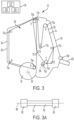
FIG. 3 is a side plan view of the round baler ofFIG. 1 . -
FIG. 3A illustrates a roller for use in the round baler ofFIG. 1 .. -
FIG. 4 is a diagram of a bearing diagnostic mode. -
FIG. 5 is a diagram of a plurality of bearings organized into bearing groups. - Before any embodiments of the disclosure are explained in detail, it is to be understood that the disclosure is not limited in its application to the details of the formation and arrangement of components set forth in the following description or illustrated in the accompanying drawings. The disclosure is capable of supporting other implementations and of being practiced or of being carried out in various ways.
- The disclosure relates to balers and more particularly to balers having a control system configured to record the overall vibrations in the frame of the baler, decompose the overall vibrations into component signals, and attribute the various component signals to pre-determined sub-groups of bearings located within the baler itself. Once the component signals have been decomposed and attributed, the controller is configured to monitor the decomposed signals over a period of time, apply the decomposed signals to one or more algorithms generally modeling the lifecycle of the applicable bearings, and output alerts to the user regarding the operational status of each sub-group of bearings. More specifically, the controller is configured to monitor the operation of each sub-group of bearings and output an alert to the user when a failure condition is detected. By only requiring the overall or bulk vibration signal as an input to the system, the system is able to monitor multiple bearings within the baler while only requiring the presence of a single accelerometer.
- Referring to
FIG. 1 , abaler 10 includes aframe 14, a set ofwheels 18 mounted to theframe 14, abale forming system 26, and acontroller 36 to monitor and direct the baling operations. During use, thebale forming system 26 is configured to collect and process crop material into individual bales. In the illustrated implementation, thebaler 10 is a round baler for creating cylindrical finished bales of a crop material, such as hay, straw, or other biomasses. However, in other embodiments thecontroller 36 may be installed on different forms of balers with rotational elements included therein, such as rectangular balers and the like. - The
baler 10 includes a leadingend 30 facing the direction of travel T, atrailing end 34 opposite the leadingend 30, a first orleft side 38, and a second orright side 42. Thebaler 10 also defines a longitudinal axis 46 positioned at the lateral center of the baler 10 (e.g., midway between the first andsecond sides 38, 42) and extending through the leading andtrailing ends 30, 34 (e.g., perpendicular to thewheel axis 50; seeFig. 2 ). - In the illustrated implementation, the
frame 14 of thebaler 10 includes a collection offramework 54 and housing elements or panels 58 configured to at least partially enclose and support thebale forming system 26. More specifically, theframe 14 of the illustratedbaler 10 includes a steel frame formed from multiple elongated elements welded or otherwise coupled together including, but not limited to, across-tube 62 and atongue 66. Thecross-tube 62 of theframe 14 includes an elongated member oriented perpendicular to the longitudinal axis 46 (e.g., perpendicular to the wheel axis 50) and extending approximately the entire width of thebaler 10. Thecross-tube 62 is also positioned proximate the leadingend 30 of thebaler 10 such that thetongue 66 extends outwardly, generally in the direction of travel T, therefrom. - The
frame 14 also includes a series of panels 58 at least partially enclosing thebale forming system 26. More specifically, theframe 14 at least includes afirst side panel 58a at least partially enclosing thefirst side 38 of thebaler 10 and asecond side panel 58b at least partially enclosing thesecond side 42 of thebaler 10. Bothside panels 58a, b are generally formed from sheet material (e.g., sheet metal) and coupled to theunderlying framework 54. - The
frame 14 also forms a gate ordoor 60 at thetrailing end 34 thereof to provide selective access to abale chamber 64 in which the bale is formed. During use, thegate 60 is pivotable with respect to theframe 14 between an open position, in which thebale chamber 64 is accessible from the outside, and a closed position, in which thebale chamber 64 cannot be accessed from the outside. Thegate 60 may also define a "gate angle" between thegate 60 and theframe 14. In the illustrated embodiment, a gate angle of 0 degrees represents thegate 60 in the closed position while the gate angle increases as the gate pivots toward the open position. - Illustrated in
FIG. 1 , thebale forming system 26 includes a plurality ofrollers 70, belts 74, and other rotational elements that together are configured to both directly and indirectly support and handle the crop material as it is formed into the desired bail shape. The specific layout and construction of thebale forming system 26 may vary depending on thespecific baler design 10. - Each
roll 70 of thebale forming system 26 includes anelongated body 78 mounted either directly or indirectly to theframe 14 via a pair ofbearings 82 for rotation with respect thereto about acorresponding roller axis 86. During operation, eachroller 70 is configured to rotate with respect to theframe 14 about aroller axis 86 at a roller speed 92 that corresponds directly with an overall operational speed of the baler 10 (e.g., as established by a reference speed). In the illustrated embodiment, eachroller 70 is generally oriented perpendicular to the longitudinal axis 46 (e.g., parallel to the wheel axis 50). However, in other embodiments, theroller axis 86 may not be oriented perpendicular to the longitudinal axis 46 and instead may be oriented differently with respect thereto. - The
bearings 82 for each roller 70are generally classified into one of a plurality of different bearing types 94. Each bearing type 94, in turn, is established by a number of different bearing attributes including, but not limited to, the bearing dimensions, the bearing element number (e.g., the number of bearing elements present in the bearing), the bearing material (e.g., the material of the bearing race and/or bearing elements), the bearing element style (e.g., roller elements, ball elements, needle elements, and the like), the bearing layout (e.g., thrust bearings, tapered bearings, deep groove bearings, sealed bearings, and the like), and any combination thereof. In some embodiments, a sub-set of the above-listed attributes may be taken into account when establishing bearing types 94. For example, in some embodimentsindividual bearings 82 may be classified into types 94 based solely on the bearing diameter and the bearing element number while includingbearings 82 having different bearing materials, element styles, and the like. However, in other embodiments, different combinations of attributes may be emphasized and de-emphasized when establishing the plurality of bearing types 94. - As shown in
FIG. 3 , thebale forming system 26 includes one or more drive rolls 70a, one or more idler/drive rolls 70b, one or more idler rolls 70c, one or more starter rolls 70d, and one or more gate rolls 70e. Together, therolls 70a-e, form one or more pathways about which the belts 74 may be wound and operated. Eachroll 70a-e is generally formed as an assembly including theroll body 78 and twobearings 82 on either side thereof to support theroll body 78. - Each
drive roll 70a of thebale forming system 26 includes a first bearing type 94a (e.g., the same being dimensions and bearing element number), a common firstroller axis orientation 90a (e.g., perpendicular to the longitudinal axis 46), and rotate at afirst roller speed 92a. In the illustrated embodiment, thebale forming system 26 includes twodrive rolls 70a (seeFIG. 3 ). - Each idler/
drive roll 70b of thebale forming system 26 includes a second bearing type 94b different than the first bearing type 94a of the drive rolls 70a, have a roller axis in the firstroller axis orientation 90a (e.g., perpendicular to the longitudinal axis 46), and rotate at thefirst roller speed 92a. In the illustrated embodiment, thebale forming system 26 includes a single idler/drive roll 70b (seeFIG. 3 ). - Each
idler roll 70c of thebale forming system 26 includes the first bearing type 94a and a rotation axis in the firstroller axis orientation 90a. Eachidler roll 70c rotates at asecond roller speed 92b that is different than thefirst roller speed 92a. More specifically, thesecond roller speed 92b is faster than thefirst roller speed 92a. In the illustrated embodiment, thebale forming system 26 includes sixidler rolls 70c (seeFIG. 3 ). - Each
starter roll 70d of thebale forming system 26 includes a third bearing type 94c different than the first and second bearing types 94a, 94b, have a rotation axis in the firstroller axis orientation 90a, and rotate at thefirst roller speed 92a. In the illustrated embodiment, thebale forming system 26 includes onestarter roll 70d (seeFIG. 3 ). - Each
gate roll 70e of thebale forming system 26 includes a fourth bearing type 94d different than the other bearing types 94a-c. Eachgate roll 70e also has a roller axis in the firstroller axis orientation 90a and rotates at athird roller speed 92c that is different than both the first andsecond roller speeds third roller speed 92c is slower than both thefirst roller speed 92a and thesecond roller speed 92b. In the illustrated embodiment, thebale forming system 26 includes onegate roller 70e (seeFIG. 3 ). - While the illustrated
bale forming system 26 includes a "belted" system formed from a combination of the above describedroll types 70a-e and belts 74, it is understood that other roller types having different combinations of bearing types, axis orientations, and rotational speeds may also be present as needed. Furthermore, a non-belted style ofbale forming system 26 may be implemented in some embodiments. - In addition to the
rollers 70a-e described above, thebale forming system 26 may also include other rotational elements that are supported bybearings 82. For example, augers, rotary tine pickups, and the like may be supported bybearings 82 having a pre-determined bearing type 94, rotate about an axis of rotation having a predetermined axis orientation 90, and rotate at a predetermined operational speed 92. In such embodiments, the below described bearing monitoring features may also be applied to other rotational elements used in thebaler 10 beyond the roller described herein. - Illustrated in
FIGS. 1-3 , thecontroller 36 of thebaler 10 includes aprocessor 100, amemory unit 104 in operable communication with theprocessor 100, one ormore sensors 108 sending and receiving signals with theprocessor 100, and auser interface 112 in operable communication with theprocessor 100. Theprocessor 100 may also be in operable communication with various elements of thebaler 10 such as drive motors, position sensors, actuators, and the like. During use, theprocessor 100 receives signals from the one ormore sensors 108 representative of the overall vibrational power levels in theframe 14, enters the overall vibrational information into one or more algorithms to decompose the vibrational information into a series of component signals, associates the component signals with a corresponding sub-set or group of elements within thebaler 10, and then enters the component signals with corresponding group information into another algorithm to monitor and track the operational health of thebearings 82 contained within each group. Upon detection that one or more groups are operating outside the predetermined parameters theprocessor 100 is configured to output an alert to the user via theuser interface 112. By way of the above algorithm, theprocessor 100 of thebaler 10 is able to monitor the health ofmultiple bearings 82 within thebaler 10 using asingle accelerometer 108 attached to theframe 14 thereof. - In particular, the
baler 10 includes anaccelerometer 108 coupled to theframe 14 and configured to detect any vibrational energy in theframe 14 itself. More specifically, thebaler 10 includes asingle accelerometer 108 fixedly coupled to thecross-tube 62 of theframe 14 at the midpoint thereof (e.g., at the point where the longitudinal axis 46 intersects the cross-tube 62) that is configured to independently detect the magnitude of any accelerations along the X, Y, and Z axis. By being mounted securely to a major element of theframe 14 in a centralized location, theaccelerometer 108 is able to more accurately monitor the overall vibrational motion of thebaler 10, therollers 70, and other rotational elements attached thereto. In the illustrated embodiment, theaccelerometer 108 includes an Aceinna IMU, however in other embodiments different units having different technical capabilities may be used. Furthermore, while the illustratedaccelerometer 108 is mounted directly to the middle of the cross-tube 62, it is understood that in other embodiments theaccelerometer 108 may be mounted to other points of theframe 14 including, but not limited to, other positioned on theframework 54 or the panels 58. - While the illustrated
baler 10 includes asingle accelerometer 108 mounted to the midpoint of the cross-tube 62, it is understood that in other embodimentsmore accelerometers 108 may be present in the same or different locations. For example, in some embodiments thebaler 10 may include a pair ofaccelerometers 108 mounted on either end of the cross-tube 62. In still other embodiments, theaccelerometers 108 may be mounted to theside panels multiple accelerometers 108 are present, theaccelerometers 108 may be used to each individually monitor the vibrational outputs of a sub-set of thebearings 82 present in a baler 10 - especially in embodiments where thebaler 10 includes a sub-frame that is isolated from theframe 14. In still other embodiments, themultiple accelerometers 108 may combine their readings to help achieve greater accuracy and fidelity when monitoring a greater number ofbearings 82 in thebaler 10. - During operation of the
baler 10, theprocessor 100 may enter a bearingdiagnostic mode 116. Entry into the bearingdiagnostic mode 116 may be initiated by the user via theuser interface 112 or be triggered automatically by theprocessor 100 itself. In embodiments where the bearingdiagnostic mode 116 is triggered automatically, theprocessor 100 may do so based on a pre-determined service interval (e.g., after a pre-determined number of hours of operation have passed or every so many calendar days), may be triggered automatically every time the diagnostic conditions are present, may be initiated to correspond with other maintenance tasks associated with the baler, and the like. - Once the bearing
diagnostic mode 116 is triggered, theprocessor 100 is configured to first determine whether the necessary conditions exist to allow the diagnostic test to be conducted (Step 200). More specifically, the bearingdiagnostic mode 116 is configured to operate under a set of conditions that allow for maximum accuracy when conducting the analysis. Such conditions may include, but are not limited to, when thebale chamber 64 is empty (e.g., that no crop material is present therein), when thebaler 10 is operating at a pre-determined speed or within a predetermined speed range, when thebaler 10 is not traveling or if doing so is traveling below a maximum speed, when thegate 60 has reached a certain progression in the closing process, and the like. In the illustrated embodiment, theprocessor 100 is configured to initiate the bearingdiagnostic mode 116 when the gate angle reaches 10 degrees during the closing process and continues the diagnostic mode until thegate 60 reaches a closed position (e.g., the gate angle is 0). While the illustrateddiagnostic mode 116 is configured to operate over the final 10 degrees of rotation of the closing process, it is understood that in other embodiments a larger or smaller degree range may be used where more or less time is needed to collect the required volume of data. - Once the
processor 100 determines that the proper operating conditions are present, theprocessor 100 may initiate the bearingdiagnostic mode 116. When doing so, theprocessor 100 is configured to receive a stream of data from theaccelerometer 108 representative of the bulk or overall vibrational accelerations of theframe 14 measured independently along the X, Y, and Z axes (Step 204). As stated above, theprocessor 100 received the above-described data stream while thebaler 10 is running and the chamber is empty (e.g., over the period of time when thegate 60 is closing and the gate angle is less than or equal to 10 degrees). More specifically, theaccelerometer 108 will output signals representative of the overall vibrational power levels along each of the X, Y, and Z axes. - As the bulk vibration data is received from the
accelerometer 108, theprocessor 100 is then configured to decompose the bulk data into its component signals (Step 208). More specifically, thecontroller 100 is configured to process the data such that it will show the vibrational power level by frequency along each of the X, Y, and Z axes. To do so, theprocessor 100 may enter the data into one or more algorithms whose outputs would include the power level present at each frequency. In some embodiments, a Fourier transform, discrete Fourier transform, and/or fast Fourier transforms may be used dependent upon the formatting of the data and the processing power available. In other embodiments, different types of filters and/or algorithms may be used separately or in combination with the various forms of Fourier transforms to decompose and condition the data as desired. - While the
processor 100 is receiving and decomposing the bulk vibration data as described above, theprocessor 100 is also configured to calculate the rotational speed 92 of eachroller 70 within the baler 10 (Step 212). To do so, theprocessor 100 enters information regarding the baler's operating speed into one or more algorithms that model the mechanical layout of thebaler 10 including the relative rotational speeds of eachroller 70 for a given reference speed (e.g., a speed that can be verified either directly or indirectly). Using the model inmemory 104, theprocessor 100 is able to calculate mathematically the rotational speed 92 of eachroller 70 for the known reference speed at any given time during the analysis. - With the rotational speed of each
roller 70 known, theprocessor 100 is then able to calculate in real-time the bearing frequency 120 for each bearing 82 at any given time during the analysis (Step 216). Generally speaking, the bearing frequency 120 for a givenbearing 82 represents the frequency at which an individual element of the bearing 82 (e.g., an individual roller or ball) rotates about the axis ofrotation 86 of the corresponding roller 70 (e.g., travels 360 degrees about the axis of rotation 86). More specifically, theprocessor 100 is configured to enter the rotational speed 92 of a givenroller 70, the corresponding bearing size, and the corresponding bearing element number into an algorithm whereby the algorithm will mathematically calculate the corresponding bearing frequency 120. - In the illustrated embodiment, the
processor 100 includes pre-formed models of different bearing types stored in memory 104 (e.g., models containing all of the relevant bearing information for a given type) and a database matching specific bearing types tospecific rollers 70 upon which theprocessor 100 is able to reference during operation. - In the illustrated embodiment, the
processor 100 is able to minimize the number of calculations needed by grouping bearings having like conditions into a bearing group 124. More specifically, eachbearing group 124a-d contains allrollers 70 whose operating conditions establish that their associatedbearings 82 will have the same bearing frequency 120 for all operating conditions (e.g., all reasonable reference speeds). As such, theprocessor 100 need only calculate the bearing frequency 120 of oneroller 70 in each group to cover the entire group. - With the decomposed data and bearing frequencies 120 for each group established, the
processor 100 is then configured to combine the two data sets by assigning the appropriate data sets to the corresponding bearing groups 124 based at least in part on the calculated bearing frequencies 120 (Step 220). More specifically, theprocessor 100 is configured to associate the vibration power levels accruing at a given frequency with the bearing group having a similar calculated bearing frequency 120. Once associated, theprocessor 100 applies the given data values to eachroller 70 categorized within that group 124. For example, if a given vibrational power level occurs at 60Hz and Bearing Group C has a calculated bearing frequency of approximately 60 Hz (±1 %, ±1.5%, ±2%, ±2.5%) then theprocessor 100 is configured to associate the given vibration power level with all sixidler rollers 70c contained in Bearing Group C. Expanding on the example, if a second vibration power level occurs at 70Hz and Bearing Group A has a calculated bearing frequency of approximately 70Hz (±1 %, ±1.5%, ±2%, ±2.5%), the second vibration power level will be associated with both driverollers 70a contained in Bearing Group A. - During operation, the manner in which the
processor 100 associates a bearing group 124 with a particular segment of decomposed data may be set by the user and/or refined over time using machine learning. - In some embodiments, the
processor 100 may be able to further subdivide the entries within the various bearing groups 124 based on additional details if present. For example, if oneidle roller 70c' (not shown) has an axis of rotation that is set at 90 degrees to the otheridle rollers 70c, theprocessor 100 may be able to further deduce what portion of the vibration power levels occurring at 60Hz are applicable to just the skewedroller 70c' based on how the vibration power levels are distributed between the X, Y, and Z axes. While the given example is based on orientation, such deductions may also be made based at least in part on, but not limited to, bearing material, bearing element type, and the like where a feature of the signal can be deduced and attributed to the differing feature. - After the
processor 100 has completed associating the decomposed vibration data with the various bearing groups 124, theprocessor 100 may save the data inmemory 104 and perform a performance analysis for thebearings 82 in each group 124. More specifically, the performance analysis may consist of both an instantaneous analysis (Step 224) and a long-term or life-cycle analysis (Step 228). - For the instantaneous analysis, the
processor 100 is configured to compare the current operating conditions to a set of pre-determined operating envelopes regardless of past performance. More specifically, theprocessor 100 has operating envelopes (e.g., acceptable vibration maximums, acceptable vibration wave form, and the like) saved inmemory 112 for each bearing type which it can call upon during the analysis. If the instantaneous data is determined to fall outside the acceptable envelope, theprocessor 100 is configured to output an alert to the user via theuser interface 112 indicating that one ormore bearings 82 in the specified group (e.g., Bearing Group A, B, C, or D) have failed or are operating outside the acceptable parameters and should be replaced. In some embodiments, theprocessor 100 may further take intervening steps in view of an instantaneous alert such as, but not limited to, shutting the baler down, shutting down the portion of thebaler 10 associated with the failed bearing group, initiate countermeasures (e.g., fire suppression), and the like. - In addition to instantaneous alerts, the
processor 100 is also configured to monitor life-cycle alerts. More specifically, theprocessor 100 is configured to enter the decomposed and associated data into one or more algorithms configured to map out the anticipated wear cycle of a given bearing type 94 over time. More specifically, theprocessor 100 is configured to fit the recently acquired data to the statistical model to calculate how far along thebearing 82 is in its anticipated life-cycle and how much life remains before thebearing 82 should be replaced. In some embodiments, theprocessor 100 may also use machine learning techniques to update and correct the statistical model based on past data entries (e.g., either local to thecurrent baler 10 or compiled from likebalers 10 on a network). In the illustrated embodiment, theprocessor 100 is configured to monitor the magnitude of the vibration power level associated with a particular bearing group 124 over time. When the power level exceeds a predetermined maximum value or grows at a rate exceeding a predetermined maximum rate theprocessor 100 is configured to output an alert to the user via theuser interface 112. More specifically, theprocessor 100 will output an alert to the user indicating that one or more bearings in the identified bearing group 124 has fallen out of specification and needs to be replaced. In instances where multiple trigger levels are present (e.g., a low, medium, and high trigger levels), the alert may also include the level that has been breached and the tasks required to remedy it (e.g., replacement, adjustment, etc.). In still other embodiments, theprocessor 100 may further take intervening steps in view of lifecycle alert such as, but not limited to, shutting the baler down, shutting down the portion of thebaler 10 associated with the failed bearing group, initiate countermeasures (e.g., fire suppression), and the like.
Claims (15)
- A baler comprising:a frame;one or more wheels rotatably mounted to the frame;a bale forming system including:a first rotational element rotatably coupled to the frame by a first bearing for rotation about a first axis, wherein the first bearing is a first bearing type, anda second rotational element rotatably coupled to the frame by a second bearing for rotation about a second axis, wherein the second bearing is a second bearing type different than the first bearing type;an accelerometer coupled to the frame and configured to output a bulk signal representative of the total vibrational power in the frame; anda controller in operable communication with the accelerometer, where the controller is configured to deconstruct the bulk output signal provided by the accelerometer into at least a first component signal and a second component signal, and wherein the controller is configured to associate one of the first component signal and the second component signal with the first bearing andthe other of the first component signal and the second component signal with the second bearing.
- The baler of claim 1, wherein the controller deconstructs the bulk output signal into two or more component by decomposing the component vibration power levels by frequency.
- The baler of claim 1 or 2, wherein the controller deconstructs the bulk output signal by passing the bulk output signal through a form of a Fourier transform.
- The baler according to at least one of the preceding claims, wherein the first rotational element rotates about the first axis at a first rotational speed, and wherein the controller is configured to calculate a first bearing frequency for the first bearing based at least on the first rotational speed.
- The baler according to at least one of the preceding claims, wherein the controller associates one of the first component signal and the second component signal with the first bearing based at least in part on the first bearing frequency.
- The baler according to at least one of the preceding claims, wherein the controller is configured to compare at least one of the first component signal and the second component signal with a pre-determined set of operating parameters.
- The baler according to at least one of the preceding claims, wherein the predetermined set of parameters are modeled at least in part on the first bearing type.
- The baler according to at least one of the preceding claims, wherein the first rotational element rotates about the first axis and the second rotational element rotates about the second axis at the same speed.
- The baler according to at least one of the preceding claims, wherein at least one of the first rotating element and the second rotating element includes a roller configured to at least partially support a belt thereon.
- The baler according to at least one of the preceding claims, wherein the controller is configured to calculate a first bearing frequency for the first bearing based at least in part on the bearing size and the bearing element number.
- The baler according to at least one of the preceding claims, wherein the first rotational element is part of a first bearing group, and wherein each rotational element of the first bear group shares a common attribute.
- The baler according to at least one of the preceding claims, where each rotational element of the first bearing group have the same bearing frequency.
- The baler according to at least one of the preceding claims, further comprising associating the component signal with a given bearing group by matching the calculated bearing frequency with the component vibration power level frequency.
- The baler according to at least one of the preceding claims, wherein the accelerometer is configured to output the bulk signal in an X, Y, and Z axis subcomponent.
- A method of monitoring the health of a plurality of bearing groups in a baler, in particular a baler according to at least one of the claims 1 to 14, having an accelerometer fixedly coupled to the frame thereof, the method comprising:outputting a bulk signal representative of the vibrational power within the frame;deconstructing the bulk signal into two or more component signals;associating at least one of the component signals with a corresponding bearing group;comparing the at least one component signal to a corresponding set of operational parameters; andoutputting an alert to the user if the at least one component signal falls outside the corresponding set of operational parameters.
Applications Claiming Priority (1)
| Application Number | Priority Date | Filing Date | Title |
|---|---|---|---|
| US18/178,309 US20240295467A1 (en) | 2023-03-03 | 2023-03-03 | Baler with bearing health monitor |
Publications (2)
| Publication Number | Publication Date |
|---|---|
| EP4424141A1 true EP4424141A1 (en) | 2024-09-04 |
| EP4424141B1 EP4424141B1 (en) | 2025-09-17 |
Family
ID=89983234
Family Applications (1)
| Application Number | Title | Priority Date | Filing Date |
|---|---|---|---|
| EP24158041.4A Active EP4424141B1 (en) | 2023-03-03 | 2024-02-16 | Baler with bearing health monitor |
Country Status (3)
| Country | Link |
|---|---|
| US (1) | US20240295467A1 (en) |
| EP (1) | EP4424141B1 (en) |
| CA (1) | CA3227925A1 (en) |
Citations (3)
| Publication number | Priority date | Publication date | Assignee | Title |
|---|---|---|---|---|
| US6053047A (en) * | 1998-09-29 | 2000-04-25 | Allen-Bradley Company, Llc | Determining faults in multiple bearings using one vibration sensor |
| US20050155429A1 (en) * | 2002-04-13 | 2005-07-21 | I-For-T Gmbh | Vibration sensor and method for monitoring the condition of rotating components and bearings |
| US20210223094A1 (en) * | 2009-05-05 | 2021-07-22 | S.P.M. Instrument Ab | Apparatus and a method for analysing the vibration of a machine having a rotating part |
Family Cites Families (3)
| Publication number | Priority date | Publication date | Assignee | Title |
|---|---|---|---|---|
| US11385137B2 (en) * | 2018-02-15 | 2022-07-12 | Amsted Rail Company, Inc. | System, method and apparatus for monitoring the health of railcar wheelsets |
| BE1026636B1 (en) * | 2018-09-20 | 2020-04-21 | Cnh Ind Belgium Nv | BALER WITH OPERATING DETECTOR |
| IT202000000928A1 (en) * | 2020-01-20 | 2021-07-20 | Kverneland Group Ravenna Srl | ROUND BALER |
-
2023
- 2023-03-03 US US18/178,309 patent/US20240295467A1/en active Pending
-
2024
- 2024-02-01 CA CA3227925A patent/CA3227925A1/en active Pending
- 2024-02-16 EP EP24158041.4A patent/EP4424141B1/en active Active
Patent Citations (3)
| Publication number | Priority date | Publication date | Assignee | Title |
|---|---|---|---|---|
| US6053047A (en) * | 1998-09-29 | 2000-04-25 | Allen-Bradley Company, Llc | Determining faults in multiple bearings using one vibration sensor |
| US20050155429A1 (en) * | 2002-04-13 | 2005-07-21 | I-For-T Gmbh | Vibration sensor and method for monitoring the condition of rotating components and bearings |
| US20210223094A1 (en) * | 2009-05-05 | 2021-07-22 | S.P.M. Instrument Ab | Apparatus and a method for analysing the vibration of a machine having a rotating part |
Non-Patent Citations (1)
| Title |
|---|
| SADOUGHI MOHAMMADKAZEM ET AL: "Physics-Based Convolutional Neural Network for Fault Diagnosis of Rolling Element Bearings", IEEE SENSORS JOURNAL, IEEE, USA, vol. 19, no. 11, 10 February 2019 (2019-02-10), pages 4181 - 4192, XP011722716, ISSN: 1530-437X, [retrieved on 20190503], DOI: 10.1109/JSEN.2019.2898634 * |
Also Published As
| Publication number | Publication date |
|---|---|
| CA3227925A1 (en) | 2025-06-30 |
| US20240295467A1 (en) | 2024-09-05 |
| EP4424141B1 (en) | 2025-09-17 |
Similar Documents
| Publication | Publication Date | Title |
|---|---|---|
| CA2367284C (en) | Monitoring device for a working vehicle | |
| DE112009004322B4 (en) | Diaphragm pump and blood pressure monitor | |
| EP1564688B1 (en) | Monitoring system and device for monitoring the condition of a working machine | |
| CA2367312C (en) | Monitoring device for a harvesting machine | |
| EP3803122A1 (en) | Method for determining or monitoring the state of an eccentric screw pump | |
| EP2696251A2 (en) | Method for monitoring rotating machines | |
| EP4424141B1 (en) | Baler with bearing health monitor | |
| JP5375701B2 (en) | Method, apparatus and program for estimating rotational speed of rotating machine | |
| CN104823035A (en) | Monitoring device for rotary machine | |
| CN103134679A (en) | Bearing condition monitoring method and bearing condition monitoring device | |
| CN107454925A (en) | For the method for the remaining life for determining wind energy plant | |
| CN107909156A (en) | A kind of equipment state detecting method and computing device | |
| JP2023542501A (en) | Mechanical face seal assembly operating method and mechanical face seal assembly | |
| Yilmaz et al. | Development of a measurement system for noise and vibration of combine harvester | |
| US9089091B2 (en) | Method and system for controlling an operating parameter of a harvesting machine | |
| Gago et al. | Towards an intelligent decision support system for intensive care units | |
| CN118679906A (en) | Optimal wind pressure decision method, system and storage medium for pneumatic seeding operation | |
| CN113945380B (en) | Threshing cylinder bearing vibration fault analysis method and system and combine harvester | |
| CN118788070B (en) | A dust removal monitoring system | |
| US20260104698A1 (en) | Machine monitoring device and methods for high accuracy wireless continuous machine health monitoring and fault diagnosis | |
| EP4636378A1 (en) | Condition monitoring device and storage medium | |
| JPH10332475A (en) | Method of diagnosing deterioration of rotating machine elements | |
| CN121444709A (en) | Caterpillar self-propelled intelligent traditional Chinese medicine harvester and control method thereof | |
| CN118476377B (en) | System and method for diagnosing and regulating state of separation and cleaning device based on transfer learning | |
| CN121971799A (en) | Impeller condition monitoring methods, blood pumps, devices, electronic equipment and storage media |
Legal Events
| Date | Code | Title | Description |
|---|---|---|---|
| PUAI | Public reference made under article 153(3) epc to a published international application that has entered the european phase |
Free format text: ORIGINAL CODE: 0009012 |
|
| STAA | Information on the status of an ep patent application or granted ep patent |
Free format text: STATUS: THE APPLICATION HAS BEEN PUBLISHED |
|
| AK | Designated contracting states |
Kind code of ref document: A1 Designated state(s): AL AT BE BG CH CY CZ DE DK EE ES FI FR GB GR HR HU IE IS IT LI LT LU LV MC ME MK MT NL NO PL PT RO RS SE SI SK SM TR |
|
| STAA | Information on the status of an ep patent application or granted ep patent |
Free format text: STATUS: REQUEST FOR EXAMINATION WAS MADE |
|
| 17P | Request for examination filed |
Effective date: 20250304 |
|
| RIC1 | Information provided on ipc code assigned before grant |
Ipc: A01F 15/18 20060101ALI20250404BHEP Ipc: G01M 13/045 20190101ALI20250404BHEP Ipc: A01F 15/07 20060101AFI20250404BHEP |
|
| GRAP | Despatch of communication of intention to grant a patent |
Free format text: ORIGINAL CODE: EPIDOSNIGR1 |
|
| STAA | Information on the status of an ep patent application or granted ep patent |
Free format text: STATUS: GRANT OF PATENT IS INTENDED |
|
| INTG | Intention to grant announced |
Effective date: 20250519 |
|
| GRAS | Grant fee paid |
Free format text: ORIGINAL CODE: EPIDOSNIGR3 |
|
| GRAA | (expected) grant |
Free format text: ORIGINAL CODE: 0009210 |
|
| STAA | Information on the status of an ep patent application or granted ep patent |
Free format text: STATUS: THE PATENT HAS BEEN GRANTED |
|
| AK | Designated contracting states |
Kind code of ref document: B1 Designated state(s): AL AT BE BG CH CY CZ DE DK EE ES FI FR GB GR HR HU IE IS IT LI LT LU LV MC ME MK MT NL NO PL PT RO RS SE SI SK SM TR |
|
| REG | Reference to a national code |
Ref country code: GB Ref legal event code: FG4D |
|
| REG | Reference to a national code |
Ref country code: CH Ref legal event code: EP |
|
| REG | Reference to a national code |
Ref country code: IE Ref legal event code: FG4D |
|
| REG | Reference to a national code |
Ref country code: DE Ref legal event code: R096 Ref document number: 602024000667 Country of ref document: DE |
|
| PG25 | Lapsed in a contracting state [announced via postgrant information from national office to epo] |
Ref country code: NO Free format text: LAPSE BECAUSE OF FAILURE TO SUBMIT A TRANSLATION OF THE DESCRIPTION OR TO PAY THE FEE WITHIN THE PRESCRIBED TIME-LIMIT Effective date: 20251217 |
|
| REG | Reference to a national code |
Ref country code: LT Ref legal event code: MG9D |
|
| PG25 | Lapsed in a contracting state [announced via postgrant information from national office to epo] |
Ref country code: FI Free format text: LAPSE BECAUSE OF FAILURE TO SUBMIT A TRANSLATION OF THE DESCRIPTION OR TO PAY THE FEE WITHIN THE PRESCRIBED TIME-LIMIT Effective date: 20250917 |
|
| PG25 | Lapsed in a contracting state [announced via postgrant information from national office to epo] |
Ref country code: HR Free format text: LAPSE BECAUSE OF FAILURE TO SUBMIT A TRANSLATION OF THE DESCRIPTION OR TO PAY THE FEE WITHIN THE PRESCRIBED TIME-LIMIT Effective date: 20250917 |
|
| PG25 | Lapsed in a contracting state [announced via postgrant information from national office to epo] |
Ref country code: GR Free format text: LAPSE BECAUSE OF FAILURE TO SUBMIT A TRANSLATION OF THE DESCRIPTION OR TO PAY THE FEE WITHIN THE PRESCRIBED TIME-LIMIT Effective date: 20251218 |
|
| PG25 | Lapsed in a contracting state [announced via postgrant information from national office to epo] |
Ref country code: SE Free format text: LAPSE BECAUSE OF FAILURE TO SUBMIT A TRANSLATION OF THE DESCRIPTION OR TO PAY THE FEE WITHIN THE PRESCRIBED TIME-LIMIT Effective date: 20250917 |
|
| REG | Reference to a national code |
Ref country code: NL Ref legal event code: MP Effective date: 20250917 |
|
| PG25 | Lapsed in a contracting state [announced via postgrant information from national office to epo] |
Ref country code: LV Free format text: LAPSE BECAUSE OF FAILURE TO SUBMIT A TRANSLATION OF THE DESCRIPTION OR TO PAY THE FEE WITHIN THE PRESCRIBED TIME-LIMIT Effective date: 20250917 |
|
| PG25 | Lapsed in a contracting state [announced via postgrant information from national office to epo] |
Ref country code: BG Free format text: LAPSE BECAUSE OF FAILURE TO SUBMIT A TRANSLATION OF THE DESCRIPTION OR TO PAY THE FEE WITHIN THE PRESCRIBED TIME-LIMIT Effective date: 20250917 |
|
| PG25 | Lapsed in a contracting state [announced via postgrant information from national office to epo] |
Ref country code: RS Free format text: LAPSE BECAUSE OF FAILURE TO SUBMIT A TRANSLATION OF THE DESCRIPTION OR TO PAY THE FEE WITHIN THE PRESCRIBED TIME-LIMIT Effective date: 20251217 |
|
| PG25 | Lapsed in a contracting state [announced via postgrant information from national office to epo] |
Ref country code: NL Free format text: LAPSE BECAUSE OF FAILURE TO SUBMIT A TRANSLATION OF THE DESCRIPTION OR TO PAY THE FEE WITHIN THE PRESCRIBED TIME-LIMIT Effective date: 20250917 |
|
| REG | Reference to a national code |
Ref country code: AT Ref legal event code: MK05 Ref document number: 1837425 Country of ref document: AT Kind code of ref document: T Effective date: 20250917 |
|
| PG25 | Lapsed in a contracting state [announced via postgrant information from national office to epo] |
Ref country code: SM Free format text: LAPSE BECAUSE OF FAILURE TO SUBMIT A TRANSLATION OF THE DESCRIPTION OR TO PAY THE FEE WITHIN THE PRESCRIBED TIME-LIMIT Effective date: 20250917 |
|
| PG25 | Lapsed in a contracting state [announced via postgrant information from national office to epo] |
Ref country code: ES Free format text: LAPSE BECAUSE OF FAILURE TO SUBMIT A TRANSLATION OF THE DESCRIPTION OR TO PAY THE FEE WITHIN THE PRESCRIBED TIME-LIMIT Effective date: 20250917 |
|
| PGFP | Annual fee paid to national office [announced via postgrant information from national office to epo] |
Ref country code: DE Payment date: 20260121 Year of fee payment: 3 |
|
| PG25 | Lapsed in a contracting state [announced via postgrant information from national office to epo] |
Ref country code: AT Free format text: LAPSE BECAUSE OF FAILURE TO SUBMIT A TRANSLATION OF THE DESCRIPTION OR TO PAY THE FEE WITHIN THE PRESCRIBED TIME-LIMIT Effective date: 20250917 |
|
| PG25 | Lapsed in a contracting state [announced via postgrant information from national office to epo] |
Ref country code: IT Free format text: LAPSE BECAUSE OF FAILURE TO SUBMIT A TRANSLATION OF THE DESCRIPTION OR TO PAY THE FEE WITHIN THE PRESCRIBED TIME-LIMIT Effective date: 20250917 |
|
| PG25 | Lapsed in a contracting state [announced via postgrant information from national office to epo] |
Ref country code: IS Free format text: LAPSE BECAUSE OF FAILURE TO SUBMIT A TRANSLATION OF THE DESCRIPTION OR TO PAY THE FEE WITHIN THE PRESCRIBED TIME-LIMIT Effective date: 20260117 |
|
| PGFP | Annual fee paid to national office [announced via postgrant information from national office to epo] |
Ref country code: FR Payment date: 20260225 Year of fee payment: 3 |
|
| PG25 | Lapsed in a contracting state [announced via postgrant information from national office to epo] |
Ref country code: CZ Free format text: LAPSE BECAUSE OF FAILURE TO SUBMIT A TRANSLATION OF THE DESCRIPTION OR TO PAY THE FEE WITHIN THE PRESCRIBED TIME-LIMIT Effective date: 20250917 Ref country code: PT Free format text: LAPSE BECAUSE OF FAILURE TO SUBMIT A TRANSLATION OF THE DESCRIPTION OR TO PAY THE FEE WITHIN THE PRESCRIBED TIME-LIMIT Effective date: 20260119 |
|
| PG25 | Lapsed in a contracting state [announced via postgrant information from national office to epo] |
Ref country code: PL Free format text: LAPSE BECAUSE OF FAILURE TO SUBMIT A TRANSLATION OF THE DESCRIPTION OR TO PAY THE FEE WITHIN THE PRESCRIBED TIME-LIMIT Effective date: 20250917 |
|
| PG25 | Lapsed in a contracting state [announced via postgrant information from national office to epo] |
Ref country code: EE Free format text: LAPSE BECAUSE OF FAILURE TO SUBMIT A TRANSLATION OF THE DESCRIPTION OR TO PAY THE FEE WITHIN THE PRESCRIBED TIME-LIMIT Effective date: 20250917 Ref country code: SK Free format text: LAPSE BECAUSE OF FAILURE TO SUBMIT A TRANSLATION OF THE DESCRIPTION OR TO PAY THE FEE WITHIN THE PRESCRIBED TIME-LIMIT Effective date: 20250917 |