EP4424112B1 - Selecting and rendering a transition between light scenes based on lighting device orientation and/or shape - Google Patents
Selecting and rendering a transition between light scenes based on lighting device orientation and/or shape Download PDFInfo
- Publication number
- EP4424112B1 EP4424112B1 EP22802173.9A EP22802173A EP4424112B1 EP 4424112 B1 EP4424112 B1 EP 4424112B1 EP 22802173 A EP22802173 A EP 22802173A EP 4424112 B1 EP4424112 B1 EP 4424112B1
- Authority
- EP
- European Patent Office
- Prior art keywords
- light
- transition
- lighting device
- light scene
- scene
- Prior art date
- Legal status (The legal status is an assumption and is not a legal conclusion. Google has not performed a legal analysis and makes no representation as to the accuracy of the status listed.)
- Active
Links
Images


Classifications
-
- H—ELECTRICITY
- H05—ELECTRIC TECHNIQUES NOT OTHERWISE PROVIDED FOR
- H05B—ELECTRIC HEATING; ELECTRIC LIGHT SOURCES NOT OTHERWISE PROVIDED FOR; CIRCUIT ARRANGEMENTS FOR ELECTRIC LIGHT SOURCES, IN GENERAL
- H05B45/00—Circuit arrangements for operating light-emitting diodes [LED]
- H05B45/20—Controlling the colour of the light
-
- H—ELECTRICITY
- H05—ELECTRIC TECHNIQUES NOT OTHERWISE PROVIDED FOR
- H05B—ELECTRIC HEATING; ELECTRIC LIGHT SOURCES NOT OTHERWISE PROVIDED FOR; CIRCUIT ARRANGEMENTS FOR ELECTRIC LIGHT SOURCES, IN GENERAL
- H05B47/00—Circuit arrangements for operating light sources in general, i.e. where the type of light source is not relevant
- H05B47/10—Controlling the light source
- H05B47/105—Controlling the light source in response to determined parameters
-
- H—ELECTRICITY
- H05—ELECTRIC TECHNIQUES NOT OTHERWISE PROVIDED FOR
- H05B—ELECTRIC HEATING; ELECTRIC LIGHT SOURCES NOT OTHERWISE PROVIDED FOR; CIRCUIT ARRANGEMENTS FOR ELECTRIC LIGHT SOURCES, IN GENERAL
- H05B47/00—Circuit arrangements for operating light sources in general, i.e. where the type of light source is not relevant
- H05B47/10—Controlling the light source
- H05B47/155—Coordinated control of two or more light sources
-
- H—ELECTRICITY
- H05—ELECTRIC TECHNIQUES NOT OTHERWISE PROVIDED FOR
- H05B—ELECTRIC HEATING; ELECTRIC LIGHT SOURCES NOT OTHERWISE PROVIDED FOR; CIRCUIT ARRANGEMENTS FOR ELECTRIC LIGHT SOURCES, IN GENERAL
- H05B47/00—Circuit arrangements for operating light sources in general, i.e. where the type of light source is not relevant
- H05B47/10—Controlling the light source
- H05B47/175—Controlling the light source by remote control
- H05B47/19—Controlling the light source by remote control via wireless transmission
-
- H—ELECTRICITY
- H05—ELECTRIC TECHNIQUES NOT OTHERWISE PROVIDED FOR
- H05B—ELECTRIC HEATING; ELECTRIC LIGHT SOURCES NOT OTHERWISE PROVIDED FOR; CIRCUIT ARRANGEMENTS FOR ELECTRIC LIGHT SOURCES, IN GENERAL
- H05B47/00—Circuit arrangements for operating light sources in general, i.e. where the type of light source is not relevant
- H05B47/10—Controlling the light source
- H05B47/175—Controlling the light source by remote control
- H05B47/198—Grouping of control procedures or address assignation to light sources
- H05B47/1985—Creation of lighting zones or scenes
Definitions
- the invention relates to a system for controlling a plurality of individually controllable light segments of a pixelated lighting device to render a first light scene and subsequently a second light scene.
- the invention further relates to a method of controlling a plurality of individually controllable light segments of a pixelated lighting device to render a first light scene and subsequently a second light scene.
- the invention also relates to a computer program product enabling a computer system to perform such a method.
- Pixelated lighting devices i.e. lighting devices with multiple individually controllable light segments
- Signify is selling light strips with individually addressable LEDs.
- the number of individually addressable LEDs typically ranges from 4 to 16.
- These pixelated lighting devices may be used to render entertainment light effects to accompany audio and/or video content, but also make it possible to render nice gradient effects.
- a lighting device generating a dynamic light setting based on its orientation is disclosed in US2018/0153023 A1 .
- a lighting device is disclosed, which can generate a first light setting based on the orientation of a lighting device and a second light setting when a reorientation of the lighting device is detected.
- US 2019/0335560 A1 discloses a lighting device which comprises an array of controllable light emitting pixels, each pixel having an adjustable light output color, and can render color gradients on these pixels. In an embodiment, these color gradients are dynamic. Although US 2019/0335560 A1 discloses transitions between colors of neighboring pixels, it does not disclose the use of transitions between colors of the same pixel, not even within the same dynamic gradient.
- Transitions between colors of the same pixel have implemented on single-pixel lighting devices, e.g. Hue color bulbs.
- the bulb may transition through the color space until it reaches the color of the new light scene. That way, the lamp transitions to a new color instead of just instantly showing the new color.
- Such transitions have not been implemented on pixelated lighting devices, likely because they are more difficult to implement on pixelated lighting devices. With pixelated lighting devices, a new gradient or color pattern is suddenly set when a new light scene is selected and this does not create a good user experience.
- a system for controlling a plurality of individually controllable light segments of a pixelated lighting device to render a first light scene and subsequently a second light scene comprises at least one input interface, at least one control interface, and at least one processor configured to obtain data indicative of an orientation and/or a shape of said pixelated lighting device, control, via said at least one control interface, said plurality of individually controllable light segments to render said first light scene, and receive, via said at least one input interface, input indicative of activation of said second light scene.
- Said at least one processor is further configured to select a type of transition based on said orientation and/or said shape, a first type of transition being selected for a first orientation or a first shape and a second type of transition being selected for a second orientation or a second shape, determine a transition from said first light scene to said second light scene based on said selected type of transition, control, via said at least one control interface, said plurality of individually controllable light segments to render said transition, and control, via said at least one control interface, said plurality of individually controllable light segments to render said second light scene.
- This system determines a transition from a first light scene to a second light scene for a pixelated lighting device, and more specifically, it selects a suitable transition type based on the orientation and/or the shape of the pixelated lighting device and determines the transition based this transition type.
- the use of a transition between light scenes already improves the user experience, but by selecting a suitable transition type from a plurality of transition types based on the orientation and/or the shape, an even better user experience is achieved.
- the system and the pixelated lighting device may be the same device or the system may be a component of the pixelated lighting device, for example.
- Said input may be user input.
- Said first shape may be a circle and said second shape may be a line, for example.
- Said first type of transition and said second type of transition may be different spatial transitions. These different spatial transitions are preferably transitions in different directions.
- Said first light scene and said second light scene may define color and/or brightness gradients. Gradients may be calculated based two or three colors, but it is also possible to calculate gradients based on more colors.
- said first light scene and/or said second light scene may define a (non-gradient) color and/or brightness pattern.
- said first light scene may represent multiple candles. In this case, one or more of said transition types may visualize said candles being extinguished.
- Said second light scene is normally independent of said first light scene.
- light settings from said first light scene may be shifted towards a first side of said pixelated lighting device and light settings from said second light scene may be moved in at a second side of said pixelated lighting device.
- light settings from said first light scene may be shifted towards sides of said pixelated lighting device and light settings from said second light scene may be moved in at a center of said pixelated lighting device.
- light settings from said first light scene may be shifted towards a center of said pixelated lighting device and light settings from said second light scene may be moved in at sides of said pixelated lighting device.
- Said at least one processor may be configured to select said type of transition based on said orientation of said pixelated lighting device and based on a desired spatial transition direction or an orientation of a further pixelated lighting device. This makes it possible to select the transition type such that multiple pixelated lighting devices in a room transition in the same way. For example, when a user has mounted multiple light strips horizontally, the orientations of the strips may differ depending on the location of the closest power socket.
- a desired spatial transition direction e.g. left-to-right, right-to-left, or symmetric, may be configured in the system, e.g. by the manufacturer or by a user.
- a spatial transition direction setting of individual pixelated lighting devices may be overridden.
- Said at least one processor may be configured to select said type of transition further based on a position of said pixelated lighting device. For example, if said orientation of said pixelated lighting device is vertical, a transition which comprises moving out light settings from said first light scene at a side of said pixelated lighting device which is farthest from a wall or floor and moving in light settings from said second light scene at a side of said pixelated lighting device which is closest to said wall or floor may be considered most suitable and may therefore be selected.
- Said processor may be configured to determine said side farthest from the wall or floor and said side closest to the wall or floor based on the position.
- Said at least one processor may be configured to select said type of transition further based on a user preference. If multiple transition types are suitable for a certain orientation and/or shape of the pixelated lighting device, the user preference may be used to select from these multiple transition types.
- a method of controlling a plurality of individually controllable light segments of a pixelated lighting device to render a first light scene and subsequently a second light scene comprises obtaining data indicative of an orientation and/or a shape of said pixelated lighting device, controlling said plurality of individually controllable light segments to render said first light scene, and receiving input indicative of activation of said second light scene.
- the method further comprises selecting a type of transition based on said orientation and/or said shape, a first type of transition being selected for a first orientation or a first shape and a second type of transition being selected for a second orientation or a second shape, determining a transition from said first light scene to said second light scene based on said selected type of transition, controlling said plurality of individually controllable light segments to render said transition, and controlling said plurality of individually controllable light segments to render said second light scene.
- Said method may be performed by software running on a programmable device. This software may be provided as a computer program product.
- a computer program for carrying out the methods described herein, as well as a non-transitory computer readable storage-medium storing the computer program are provided.
- a computer program may, for example, be downloaded by or uploaded to an existing device or be stored upon manufacturing of these systems.
- a non-transitory computer-readable storage medium stores at least one software code portion, the software code portion, when executed or processed by a computer, being configured to perform executable operations for controlling a plurality of individually controllable light segments of a pixelated lighting device to render a first light scene and subsequently a second light scene.
- the executable operations comprise obtaining data indicative of an orientation and/or a shape of said pixelated lighting device, controlling said plurality of individually controllable light segments to render said first light scene, receiving input indicative of activation of said second light scene, selecting a type of transition based on said orientation and/or said shape, a first type of transition being selected for a first orientation or a first shape and a second type of transition being selected for a second orientation or a second shape, determining a transition from said first light scene to said second light scene based on said selected type of transition, controlling said plurality of individually controllable light segments to render said transition, and controlling said plurality of individually controllable light segments to render said second light scene.
- aspects of the present invention may be embodied as a device, a method or a computer program product. Accordingly, aspects of the present invention may take the form of an entirely hardware embodiment, an entirely software embodiment (including firmware, resident software, microcode, etc.) or an embodiment combining software and hardware aspects that may all generally be referred to herein as a "circuit", "module” or “system.” Functions described in this disclosure may be implemented as an algorithm executed by a processor/microprocessor of a computer. Furthermore, aspects of the present invention may take the form of a computer program product embodied in one or more computer readable medium(s) having computer readable program code embodied, e.g., stored, thereon.
- the computer readable medium may be a computer readable signal medium or a computer readable storage medium.
- a computer readable storage medium may be, for example, but not limited to, an electronic, magnetic, optical, electromagnetic, infrared, or semiconductor system, apparatus, or device, or any suitable combination of the foregoing.
- a computer readable storage medium may include, but are not limited to, the following: an electrical connection having one or more wires, a portable computer diskette, a hard disk, a random access memory (RAM), a read-only memory (ROM), an erasable programmable read-only memory (EPROM or Flash memory), an optical fiber, a portable compact disc read-only memory (CD-ROM), an optical storage device, a magnetic storage device, or any suitable combination of the foregoing.
- a computer readable storage medium may be any tangible medium that can contain, or store, a program for use by or in connection with an instruction execution system, apparatus, or device.
- a computer readable signal medium may include a propagated data signal with computer readable program code embodied therein, for example, in baseband or as part of a carrier wave. Such a propagated signal may take any of a variety of forms, including, but not limited to, electro-magnetic, optical, or any suitable combination thereof.
- a computer readable signal medium may be any computer readable medium that is not a computer readable storage medium and that can communicate, propagate, or transport a program for use by or in connection with an instruction execution system, apparatus, or device.
- Program code embodied on a computer readable medium may be transmitted using any appropriate medium, including but not limited to wireless, wireline, optical fiber, cable, RF, etc., or any suitable combination of the foregoing.
- Computer program code for carrying out operations for aspects of the present invention may be written in any combination of one or more programming languages, including an object oriented programming language such as Java(TM), Smalltalk, C++ or the like and conventional procedural programming languages, such as the "C" programming language or similar programming languages.
- the program code may execute entirely on the user's computer, partly on the user's computer, as a stand-alone software package, partly on the user's computer and partly on a remote computer, or entirely on the remote computer or server.
- the remote computer may be connected to the user's computer through any type of network, including a local area network (LAN) or a wide area network (WAN), or the connection may be made to an external computer (for example, through the Internet using an Internet Service Provider).
- LAN local area network
- WAN wide area network
- Internet Service Provider an Internet Service Provider
- These computer program instructions may be provided to a processor, in particular a microprocessor or a central processing unit (CPU), of a general purpose computer, special purpose computer, or other programmable data processing apparatus to produce a machine, such that the instructions, which execute via the processor of the computer, other programmable data processing apparatus, or other devices create means for implementing the functions/acts specified in the flowchart and/or block diagram block or blocks.
- a processor in particular a microprocessor or a central processing unit (CPU), of a general purpose computer, special purpose computer, or other programmable data processing apparatus to produce a machine, such that the instructions, which execute via the processor of the computer, other programmable data processing apparatus, or other devices create means for implementing the functions/acts specified in the flowchart and/or block diagram block or blocks.
- These computer program instructions may also be stored in a computer readable medium that can direct a computer, other programmable data processing apparatus, or other devices to function in a particular manner, such that the instructions stored in the computer readable medium produce an article of manufacture including instructions which implement the function/act specified in the flowchart and/or block diagram block or blocks.
- the computer program instructions may also be loaded onto a computer, other programmable data processing apparatus, or other devices to cause a series of operational steps to be performed on the computer, other programmable apparatus or other devices to produce a computer implemented process such that the instructions which execute on the computer or other programmable apparatus provide processes for implementing the functions/acts specified in the flowchart and/or block diagram block or blocks.
- each block in the flowchart or block diagrams may represent a module, segment, or portion of code, which comprises one or more executable instructions for implementing the specified logical function(s).
- the functions noted in the blocks may occur out of the order noted in the figures. For example, two blocks shown in succession may, in fact, be executed substantially concurrently, or the blocks may sometimes be executed in the reverse order, depending upon the functionality involved.
- Fig. 1 shows a first embodiment of the system for controlling a plurality of individually controllable light segments of a pixelated lighting device to render a first light scene and subsequently a second light scene.
- the system is a bridge 1.
- Fig. 1 depicts two pixelated lighting devices: light strips 10 and 20.
- Light strips 10 and 20 comprise controllers 11 and 21, respectively.
- Light strip 10 comprises seven individually controllable light segments 12-18 and light strip 20 comprises six individually controllable light segments 22-27.
- Each individually controllable light segment comprises one or more light sources, e.g., LED elements.
- the bridge 1 and the light strips 10 and 20 can communicate wirelessly, e.g., via Zigbee.
- the bridge 1 is connected to a wireless LAN access point 31, e.g., via Ethernet or Wi-Fi.
- a mobile phone 33 is also able to connect to the wireless LAN access point 31, e.g., via Wi-Fi.
- the mobile phone 33 can be used to control the light strips 10 and 20 via the wireless LAN access point 31 and the bridge 1, e g. to turn the light strips on or off or to change their light settings.
- the bridge 1 comprises a receiver 3, a transmitter 4, a processor 5, and a memory 7.
- the processor 5 is configured to obtain data indicative of an orientation and/or a shape of the pixelated lighting device, control, via the transmitter 4, the individually controllable light segments 12-18 to render the first light scene, and receive, via the receiver 3, input indicative of activation of the second light scene.
- the input may be user input, for example.
- the input may be received from mobile device 33, for example.
- Data indicative of the shape of light strip 10 may be obtained, for example, from light strip 10, which may store this information in its memory.
- Data indicative of the orientation of light strip 10 may be obtained, for example, from light strip 10, which may e.g. detect this information automatically using an orientation sensor and/or may store a flag which indicates at which side the power supply is located.
- data indicative of the shape and/or the orientation of light strip 10 may be obtained, for example, from mobile device 33, which may determine this information from an image captured by a camera.
- the processor 5 is further configured to select a type of transition based on the orientation and/or the shape, determine a transition from the first light scene to the second light scene based on the selected type of transition, control, via the transmitter 4, the light segments 12-18 to render the transition, and control, via the transmitter 4, light segments 12-18 to render the second light scene.
- a first type of transition is selected for a first orientation or a first shape and a second type of transition is selected for a second orientation or a second shape.
- the transition may be determined based on other parameters than just the transition type, e.g. specifics of the first light scene and/or second light scene. In this case, the transition is more than just the transition type. If it is not, the transition type may simply be specified in the light control command. This light control command may further include an identification of the second light scene or specify light settings of the second light scene.
- the bridge 1 comprises one processor 5.
- the bridge 1 comprises multiple processors.
- the processor 5 of the bridge 1 may be a general-purpose processor, e.g., ARM-based, or an application-specific processor.
- the processor 5 of the bridge 1 may run a Unix-based operating system for example.
- the memory 7 may comprise one or more memory units.
- the memory 7 may comprise solid-state memory, for example.
- the memory 7 may be used to store a table of connected lights, for example.
- the receiver 3 and the transmitter 4 may use one or more wired or wireless communication technologies, e.g., Ethernet for communicating with the wireless LAN access point 31 and Zigbee for communicating with the light strips 10 and 20, for example.
- wired or wireless communication technologies e.g., Ethernet for communicating with the wireless LAN access point 31 and Zigbee for communicating with the light strips 10 and 20, for example.
- multiple receivers and/or multiple transmitters are used instead of a single receiver and a single transmitter.
- a separate receiver and a separate transmitter are used.
- the receiver 3 and the transmitter 4 are combined into a transceiver.
- the bridge 1 may comprise other components typical for a network device such as a power connector.
- the invention may be implemented using a computer program running on one or more processors.
- the pixelated lighting devices 10 and 20 are light strips. Light strips can normally be installed in a line shape and can sometimes be installed in a circle shape. Pixelated lighting devices may be also sold in a form in which they have a circle shape.
- Fig. 2 shows an example of such a pixelated lighting device, e.g. a bathroom mirror lamp.
- Pixelated lighting device 40 has light segments 12-18 positioned in a circle shape. Light segment 18 is connected to controller 11. For a circle-shaped pixelating lighting device, a transition from left-to-right or from right-to-left may not look very nice and blending in the new light scene per light segment (i.e. per pixel) may look nicer.
- Fig. 3 shows a second embodiment of the system for controlling a plurality of individually controllable light segments of a pixelated lighting device to render a first light scene and subsequently a second light scene.
- the system is a pixelated lighting device 50.
- Fig. 3 also depicts the light strip 20 of Fig. 1 .
- the mobile device 33 controls the pixelated lighting devices 20 and 50 directly, e.g., using Bluetooth.
- the light strip 20 depicted in Figs. 1 and 3 can be controlled either via a bridge (see Fig. 1 ), e.g., using Zigbee, or directly by a mobile device (see Fig. 3 ), e.g., using Bluetooth.
- a pixelated lighting device can only be controlled via a bridge or can only be controlled directly by a mobile or non-mobile device, e.g. via a wireless connection (e.g. Bluetooth) or a wired connection (e.g. USB).
- the pixelated lighting device 50 comprises a controller 51, seven individually controllable light segments 12-18, and a control interface 56 between the controller 51 and light segments 12-18.
- the controller 51 comprises a transceiver 53, a transmitter 54, a processor 55, memory 57, and a touchscreen display 59.
- the processor 55 is configured to obtain data indicative of an orientation and/or a shape of the pixelated lighting device, e.g. from memory 57, control, via the control interface 56, the individually controllable light segments 12-18 to render the first light scene, and receive, via the receiver 53, input indicative of activation of the second light scene.
- the input may be user input, for example.
- the input may be received from mobile device 33, for example.
- the processor 55 is further configured to select a type of transition based on the orientation and/or the shape, determine a transition from the first light scene to the second light scene based on the selected type of transition, control, via the control interface 56, the light segments 12-18 to render the transition, and control, via the control interface 56, light segments 12-18 to render the second light scene.
- a first type of transition is selected for a first orientation or a first shape and a second type of transition is selected for a second orientation or a second shape.
- the memory 57 may be a flash memory and light parameters may be stored in this flash memory. These parameters may include the number of pixels, the type of light or luminaire, the shape, and/or the orientation.
- the lighting device 50 determines which transition profile/sequence to apply based on the original state the target state and the stored parameters.
- a transition type may be selected which has the objective of reducing the number of transitional colors which were not present in the original gradients.
- Each pixel may transition individually from the original color to the target color, or only the specified gradient colors may transition from original to target color and the interpolated colors may be determined by calculating a gradient.
- a gradient light scene is defined by specifying three to five colors and the colors for the other pixels are interpolated.
- the pixelated lighting device 51 comprises one processor 55.
- the pixelated lighting device 1 comprises multiple processors.
- the processor 55 of the pixelated lighting device 1 may be a general-purpose processor or an application-specific processor.
- the memory 57 may comprise one or more memory units.
- the memory 57 may comprise solid state memory, for example.
- the receiver 53 and the transmitter 54 may use one or more wireless communication technologies, e.g., Bluetooth, for communicating with the mobile device 33.
- multiple receivers and/or multiple transmitters are used instead of a single receiver and a single transmitter.
- a separate receiver and a separate transmitter are used.
- the receiver 53 and the transmitter 54 are combined into a transceiver.
- the pixelated lighting device 51 may comprise other components typical for a pixelated lighting device such as a battery and/or a power connector.
- the invention may be implemented using a computer program running on one or more processors.
- the system of the invention comprises a bridge or a pixelated lighting device.
- the system of the invention is a different device, e.g., a mobile device or a cloud computer.
- the system of the invention comprises a single device.
- the system of the invention comprises a plurality of devices.
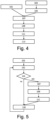
- a first embodiment of the method of controlling a plurality of individually controllable light segments of a pixelated lighting device e.g. light strip 10 of Figs. 1 and 3 ) to render a first light scene and subsequently a second light scene is shown in Fig. 4 .
- the second light scene is independent of the first light scene.
- the first light scene and the second light scene may define color and/or brightness gradients, for example.
- the method may be performed by the bridge 1 of Fig. 1 or the pixelated lighting device 50 of Fig. 3 , for example.
- a step 101 comprises obtaining data indicative of an orientation and/or a shape of the pixelated lighting device.
- a step 103 comprises controlling the plurality of individually controllable light segments to render the first light scene.
- a step 105 comprises receiving input indicative of activation of the second light scene. The input may be user input, for example.
- step 101 and steps 103 and 105 are performed at least partly in parallel.
- step 101 is performed before step 103 or after step 105.
- a step 107 is performed after steps 101 and 105 have been performed.
- Step 107 comprises selecting a type of transition based on the orientation and/or the shape.
- a first type of transition is selected if the orientation is a first orientation or the shape is a first shape and a second type of transition is selected if the orientation is a second orientation or the shape is a second shape.
- a step 109 comprises determining a transition from the first light scene to the second light scene based on the type of transition selected in step 107.
- the transition may be determined based on other parameters than just the transition type, e.g. specifics of the first light scene and/or second light scene. Determining the transition may comprise determining a transition profile/sequence. Alternatively, a transition profile/sequence may later be determined based on the transition determined in step 109, e.g. by the pixelated lighting device.
- the transition profile/sequence typically comprises multiple steps. With regard to color, any step through white is preferably avoided. With regard to brightness, steps are preferably equal. Preferably, brightness is changed at a slower rate than color.
- the duration of the transition and the duration of the steps of the transition profile/sequence may depend on the color distance(s).
- a step 111 comprises controlling the plurality of individually controllable light segments to render the transition determined in step 109.
- a step 113 comprises controlling the plurality of individually controllable light segments to render the second light scene.
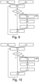
- a second embodiment of the method of controlling a plurality of individually controllable light segments of a pixelated lighting device to render a first light scene and subsequently a second light scene is shown in Fig. 5 .
- the second light scene is independent of the first light scene.
- the first light scene and the second light scene may define color and/or brightness gradients, for example.
- the method may be performed by the bridge 1 of Fig. 1 or the pixelated lighting device 50 of Fig. 3 , for example.
- Step 101 comprising obtaining data indicative of an orientation and/or a shape of the pixelated lighting device.
- a step 131 comprises receiving input indicative of activation of a light scene. The input may be user input, for example.
- a step 133 comprises determining whether the pixelated lighting device is already rendering a light scene. If so, step 107 is performed next. If not, steps 107, 109, and 111 are skipped and step 135 is performed next.
- Step 107 comprises selecting a type of transition based on the orientation and/or the shape.
- a first type of transition is selected if the orientation is a first orientation or the shape is a first shape and a second type of transition is selected if the orientation is a second orientation or the shape is a second shape.
- the type of transition may further be selected based on a user preference.
- Step 109 comprises determining a transition from the first light scene, i.e., the light scene currently being rendered, to the second light scene, i.e., the light scene whose activation was indicated in step 131, based on the type of transition selected in step 107.
- the transition may be determined based on other parameters than just the transition type, e.g. specifics of the first light scene and/or second light scene. Determining the transition may comprise determining a transition profile/sequence.
- Step 111 comprises controlling the plurality of individually controllable light segments to render the transition determined in step 109.
- Step 135 comprises controlling the plurality of individually controllable light segments to render the light scene whose activation was indicated in step 131. If both step 111 and step 135 are performed, the same light control command may be used to control the light segments to render the transition and the light scene. Step 131 is repeated after step 135, after which the method proceeds as shown in Fig. 5 .
- Figs. 6 - 8 show examples of such transitions.
- a first color gradient transitions to a second color gradient.
- the light scenes are rendered on individual controllable light segments 12-18.
- the first color gradient consists of colors 71-77.
- the second color gradient consists of colors 81-87.
- Fig. 6 shows an example in which each pixel performs a color transition the same way as a light bulb.
- all pixels simultaneously move to their assigned color in the new gradient.
- the new light scene is blended in per light segment (i.e. per pixel). While transitioning (between time t 0 and time t n ; n being larger than 1), different colors, possibly many different colors, are visible. These transitional colors may not have been present in the start or end gradient.
- FIGs. 7 and 8 A totally different way of transitioning to a new gradient is shown in Figs. 7 and 8 .
- the first transition and the second transition are different spatial transitions.
- light settings from the first light scene are shifted towards a first side of the pixelated lighting device and light settings from the second light scene are moved in at a second side of the pixelated lighting device.
- the existing gradient is shifted to the right, allowing the new gradient to come in from the left.
- colors 71 to 76 of the first color gradient have been shifted right one position compared to moment t 0 .
- the last color 87 of the second color gradient is rendered by the leftmost light segment 12 and the last color 77 of the first color gradient is no longer rendered.
- the existing gradient is shifted to the left, allowing the new gradient to come in from the right.
- colors 73 to 74 of the first color gradient and color 81 of the second color gradient have been shifted left one position compared to moment t 1 and colors 75 to 76 of the first color gradient have been shifted right one position compared to moment t 1 (and compared to moment t 0 ). Furthermore, at moment t 2 , color 82 of the second color gradient moves in at light segment 15, the last color 87 of the second color gradient moves in at light segment 16, and colors 71, 72, and 77 of the first color gradient are no longer rendered.
- light settings from the first light scene are shifted towards a center of the pixelated lighting device and light settings from the second light scene are moved in at sides of the pixelated lighting device.
- different transition types may be preferred. The preferred transition type may depend, for example, on the start and target colors, the on-off state of the light, the position and orientation of the light, as well as user preference.
- FIG. 9 A third embodiment of the method of controlling a plurality of individually controllable light segments of a pixelated lighting device to render a first light scene and subsequently a second light scene is shown in Fig. 9 .
- the third embodiment of Fig. 9 is an extension of the second embodiment of Fig. 5 .
- a step 151 is performed before step 131 of Fig. 5 and step 107 of Fig. 5 is implemented by a step 153.
- step 101 comprises determining at least the orientation of the pixelated lighting device and optionally the shape of the pixelated lighting device.
- Step 151 comprises determining a desired spatial transition direction or an orientation of a further pixelated lighting device (e.g. light strip 20 of Figs. 1 and 3 ).
- step 101 and step 151 are performed at least partly in parallel.
- step 151 is performed before step 101 or after step 101.
- Step 153 comprises selecting the type of transition based on the orientation of the pixelated lighting device, as determined in step 101, and based on the desired spatial transition direction or an orientation of a further pixelated lighting device, as determined in step 151.
- the orientations of the strips may differ depending on the location of the closest power socket.
- a desired spatial transition direction e.g. left-to-right, right-to-left, or symmetric, may be configured in the system, e.g. by the manufacturer or by a user.
- a spatial transition direction setting of individual pixelated lighting devices may be overridden.
- FIG. 10 A fourth embodiment of the method of controlling a plurality of individually controllable light segments of a pixelated lighting device to render a first light scene and subsequently a second light scene is shown in Fig. 10 .
- the fourth embodiment of Fig. 10 is an extension of the second embodiment of Fig. 5 .
- a step 171 is performed before step 131 of Fig. 5 and step 107 of Fig. 5 is implemented by a step 173.
- Step 171 comprises determining a position of the pixelated lighting device.
- step 101 and step 171 are performed at least partly in parallel.
- step 171 is performed before step 101 or after step 101.
- Step 173 comprises selecting the type of transition based on the orientation and/or the shape of the pixelated lighting device, as determined in step 101, and further based on the position of the pixelated lighting device, as determined in step 171.
- the selected transition may comprise moving out light settings from the first light scene at a side of the pixelated lighting device which is farthest from a wall or floor and moving in light settings from the second light scene at a side of the pixelated lighting device which is closest to the wall or floor.
- the side farthest from the wall or floor and the side closest to the wall or floor are determined based on the position determined in step 171.
- it may be determined whether the pixelated lighting device is closest to the wall or floor and then the side farthest from this surface and the side closest to this surface may be determined.
- the processor may receive data indicative of the position of the pixelated lighting device relative to the wall or floor via the input interface.
- the data may for example be a user input, or a sensor input.
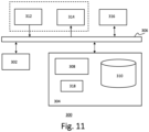
- Fig. 11 depicts a block diagram illustrating an exemplary data processing system that may perform the method as described with reference to Figs. 4-5 and 9-10 .
- the data processing system 300 may include at least one processor 302 coupled to memory elements 304 through a system bus 306. As such, the data processing system may store program code within memory elements 304. Further, the processor 302 may execute the program code accessed from the memory elements 304 via a system bus 306. In one aspect, the data processing system may be implemented as a computer that is suitable for storing and/or executing program code. It should be appreciated, however, that the data processing system 300 may be implemented in the form of any system including a processor and a memory that is capable of performing the functions described within this specification.
- the memory elements 304 may include one or more physical memory devices such as, for example, local memory 308 and one or more bulk storage devices 310.
- the local memory may refer to random access memory or other non-persistent memory device(s) generally used during actual execution of the program code.
- a bulk storage device may be implemented as a hard drive or other persistent data storage device.
- the processing system 300 may also include one or more cache memories (not shown) that provide temporary storage of at least some program code in order to reduce the quantity of times program code must be retrieved from the bulk storage device 310 during execution.
- the processing system 300 may also be able to use memory elements of another processing system, e.g. if the processing system 300 is part of a cloud-computing platform.
- I/O devices depicted as an input device 312 and an output device 314 optionally can be coupled to the data processing system.
- input devices may include, but are not limited to, a keyboard, a pointing device such as a mouse, a microphone (e.g. for voice and/or speech recognition), or the like.
- output devices may include, but are not limited to, a monitor or a display, speakers, or the like. Input and/or output devices may be coupled to the data processing system either directly or through intervening I/O controllers.
- the input and the output devices may be implemented as a combined input/output device (illustrated in Fig. 11 with a dashed line surrounding the input device 312 and the output device 314).
- a combined device is a touch sensitive display, also sometimes referred to as a "touch screen display” or simply "touch screen”.
- input to the device may be provided by a movement of a physical object, such as e.g. a stylus or a finger of a user, on or near the touch screen display.
- a network adapter 316 may also be coupled to the data processing system to enable it to become coupled to other systems, computer systems, remote network devices, and/or remote storage devices through intervening private or public networks.
- the network adapter may comprise a data receiver for receiving data that is transmitted by said systems, devices and/or networks to the data processing system 300, and a data transmitter for transmitting data from the data processing system 300 to said systems, devices and/or networks.
- Modems, cable modems, and Ethernet cards are examples of different types of network adapter that may be used with the data processing system 300.
- the memory elements 304 may store an application 318.
- the application 318 may be stored in the local memory 308, the one or more bulk storage devices 310, or separate from the local memory and the bulk storage devices.
- the data processing system 300 may further execute an operating system (not shown in Fig. 11 ) that can facilitate execution of the application 318.
- the application 318 being implemented in the form of executable program code, can be executed by the data processing system 300, e.g., by the processor 302. Responsive to executing the application, the data processing system 300 may be configured to perform one or more operations or method steps described herein.
- Fig. 11 shows the input device 312 and the output device 314 as being separate from the network adapter 316.
- input may be received via the network adapter 316 and output be transmitted via the network adapter 316.
- the data processing system 300 may be a cloud server.
- the input may be received from and the output may be transmitted to a user device that acts as a terminal.
- Various embodiments of the invention may be implemented as a program product for use with a computer system, where the program(s) of the program product define functions of the embodiments (including the methods described herein).
- the program(s) can be contained on a variety of non-transitory computer-readable storage media, where, as used herein, the expression "non-transitory computer readable storage media" comprises all computer-readable media, with the sole exception being a transitory, propagating signal.
- the program(s) can be contained on a variety of transitory computer-readable storage media.
- Illustrative computer-readable storage media include, but are not limited to: (i) non-writable storage media (e.g., read-only memory devices within a computer such as CD-ROM disks readable by a CD-ROM drive, ROM chips or any type of solid-state non-volatile semiconductor memory) on which information is permanently stored; and (ii) writable storage media (e.g., flash memory, floppy disks within a diskette drive or hard-disk drive or any type of solid-state random-access semiconductor memory) on which alterable information is stored.
- the computer program may be run on the processor 302 described herein.
Landscapes
- Engineering & Computer Science (AREA)
- Computer Networks & Wireless Communication (AREA)
- Circuit Arrangement For Electric Light Sources In General (AREA)
Description
- The invention relates to a system for controlling a plurality of individually controllable light segments of a pixelated lighting device to render a first light scene and subsequently a second light scene.
- The invention further relates to a method of controlling a plurality of individually controllable light segments of a pixelated lighting device to render a first light scene and subsequently a second light scene.
- The invention also relates to a computer program product enabling a computer system to perform such a method.
- Pixelated lighting devices, i.e. lighting devices with multiple individually controllable light segments, are becoming more readily available. For example, Signify is selling light strips with individually addressable LEDs. Depending on the size of the luminaire, the number of individually addressable LEDs typically ranges from 4 to 16. These pixelated lighting devices may be used to render entertainment light effects to accompany audio and/or video content, but also make it possible to render nice gradient effects.
- An example of a lighting device generating a dynamic light setting based on its orientation is disclosed in
US2018/0153023 A1 . A lighting device is disclosed, which can generate a first light setting based on the orientation of a lighting device and a second light setting when a reorientation of the lighting device is detected. -
US 2019/0335560 A1 discloses a lighting device which comprises an array of controllable light emitting pixels, each pixel having an adjustable light output color, and can render color gradients on these pixels. In an embodiment, these color gradients are dynamic. AlthoughUS 2019/0335560 A1 discloses transitions between colors of neighboring pixels, it does not disclose the use of transitions between colors of the same pixel, not even within the same dynamic gradient. - Transitions between colors of the same pixel have implemented on single-pixel lighting devices, e.g. Hue color bulbs. For example, when a new light scene is selected for a color bulb, the bulb may transition through the color space until it reaches the color of the new light scene. That way, the lamp transitions to a new color instead of just instantly showing the new color. Unfortunately, such transitions have not been implemented on pixelated lighting devices, likely because they are more difficult to implement on pixelated lighting devices. With pixelated lighting devices, a new gradient or color pattern is suddenly set when a new light scene is selected and this does not create a good user experience.
- It is a first object of the invention to provide a system according to
claim 1, which controls light segments of a pixelated lighting device to render a suitable transition from a first light scene to a second light scene. - It is a second object of the invention to provide a method according to
claim 13, which can be used to control light segments of a pixelated lighting device to render a suitable transition from a first light scene to a second light scene. - In a first aspect of the invention, a system for controlling a plurality of individually controllable light segments of a pixelated lighting device to render a first light scene and subsequently a second light scene comprises at least one input interface, at least one control interface, and at least one processor configured to obtain data indicative of an orientation and/or a shape of said pixelated lighting device, control, via said at least one control interface, said plurality of individually controllable light segments to render said first light scene, and receive, via said at least one input interface, input indicative of activation of said second light scene.
- Said at least one processor is further configured to select a type of transition based on said orientation and/or said shape, a first type of transition being selected for a first orientation or a first shape and a second type of transition being selected for a second orientation or a second shape, determine a transition from said first light scene to said second light scene based on said selected type of transition, control, via said at least one control interface, said plurality of individually controllable light segments to render said transition, and control, via said at least one control interface, said plurality of individually controllable light segments to render said second light scene.
- This system determines a transition from a first light scene to a second light scene for a pixelated lighting device, and more specifically, it selects a suitable transition type based on the orientation and/or the shape of the pixelated lighting device and determines the transition based this transition type. The use of a transition between light scenes already improves the user experience, but by selecting a suitable transition type from a plurality of transition types based on the orientation and/or the shape, an even better user experience is achieved.
- The system and the pixelated lighting device may be the same device or the system may be a component of the pixelated lighting device, for example. Said input may be user input. Said first shape may be a circle and said second shape may be a line, for example. Said first type of transition and said second type of transition may be different spatial transitions. These different spatial transitions are preferably transitions in different directions. Said first light scene and said second light scene may define color and/or brightness gradients. Gradients may be calculated based two or three colors, but it is also possible to calculate gradients based on more colors. Alternatively, said first light scene and/or said second light scene may define a (non-gradient) color and/or brightness pattern. For example, said first light scene may represent multiple candles. In this case, one or more of said transition types may visualize said candles being extinguished. Said second light scene is normally independent of said first light scene.
- In at least a first example of a transition type, light settings from said first light scene may be shifted towards a first side of said pixelated lighting device and light settings from said second light scene may be moved in at a second side of said pixelated lighting device.
- In a second example of a transition type, light settings from said first light scene may be shifted towards sides of said pixelated lighting device and light settings from said second light scene may be moved in at a center of said pixelated lighting device.
- In a third example of a transition type, light settings from said first light scene may be shifted towards a center of said pixelated lighting device and light settings from said second light scene may be moved in at sides of said pixelated lighting device.
- Said at least one processor may be configured to select said type of transition based on said orientation of said pixelated lighting device and based on a desired spatial transition direction or an orientation of a further pixelated lighting device. This makes it possible to select the transition type such that multiple pixelated lighting devices in a room transition in the same way. For example, when a user has mounted multiple light strips horizontally, the orientations of the strips may differ depending on the location of the closest power socket. A desired spatial transition direction, e.g. left-to-right, right-to-left, or symmetric, may be configured in the system, e.g. by the manufacturer or by a user. A spatial transition direction setting of individual pixelated lighting devices may be overridden.
- Said at least one processor may be configured to select said type of transition further based on a position of said pixelated lighting device. For example, if said orientation of said pixelated lighting device is vertical, a transition which comprises moving out light settings from said first light scene at a side of said pixelated lighting device which is farthest from a wall or floor and moving in light settings from said second light scene at a side of said pixelated lighting device which is closest to said wall or floor may be considered most suitable and may therefore be selected. Said processor may be configured to determine said side farthest from the wall or floor and said side closest to the wall or floor based on the position.
- Said at least one processor may be configured to select said type of transition further based on a user preference. If multiple transition types are suitable for a certain orientation and/or shape of the pixelated lighting device, the user preference may be used to select from these multiple transition types.
- In a second aspect of the invention, a method of controlling a plurality of individually controllable light segments of a pixelated lighting device to render a first light scene and subsequently a second light scene comprises obtaining data indicative of an orientation and/or a shape of said pixelated lighting device, controlling said plurality of individually controllable light segments to render said first light scene, and receiving input indicative of activation of said second light scene.
- The method further comprises selecting a type of transition based on said orientation and/or said shape, a first type of transition being selected for a first orientation or a first shape and a second type of transition being selected for a second orientation or a second shape, determining a transition from said first light scene to said second light scene based on said selected type of transition, controlling said plurality of individually controllable light segments to render said transition, and controlling said plurality of individually controllable light segments to render said second light scene. Said method may be performed by software running on a programmable device. This software may be provided as a computer program product.
- Moreover, a computer program for carrying out the methods described herein, as well as a non-transitory computer readable storage-medium storing the computer program are provided. A computer program may, for example, be downloaded by or uploaded to an existing device or be stored upon manufacturing of these systems.
- A non-transitory computer-readable storage medium stores at least one software code portion, the software code portion, when executed or processed by a computer, being configured to perform executable operations for controlling a plurality of individually controllable light segments of a pixelated lighting device to render a first light scene and subsequently a second light scene.
- The executable operations comprise obtaining data indicative of an orientation and/or a shape of said pixelated lighting device, controlling said plurality of individually controllable light segments to render said first light scene, receiving input indicative of activation of said second light scene, selecting a type of transition based on said orientation and/or said shape, a first type of transition being selected for a first orientation or a first shape and a second type of transition being selected for a second orientation or a second shape, determining a transition from said first light scene to said second light scene based on said selected type of transition, controlling said plurality of individually controllable light segments to render said transition, and controlling said plurality of individually controllable light segments to render said second light scene.
- As will be appreciated by one skilled in the art, aspects of the present invention may be embodied as a device, a method or a computer program product. Accordingly, aspects of the present invention may take the form of an entirely hardware embodiment, an entirely software embodiment (including firmware, resident software, microcode, etc.) or an embodiment combining software and hardware aspects that may all generally be referred to herein as a "circuit", "module" or "system." Functions described in this disclosure may be implemented as an algorithm executed by a processor/microprocessor of a computer. Furthermore, aspects of the present invention may take the form of a computer program product embodied in one or more computer readable medium(s) having computer readable program code embodied, e.g., stored, thereon.
- Any combination of one or more computer readable medium(s) may be utilized. The computer readable medium may be a computer readable signal medium or a computer readable storage medium. A computer readable storage medium may be, for example, but not limited to, an electronic, magnetic, optical, electromagnetic, infrared, or semiconductor system, apparatus, or device, or any suitable combination of the foregoing. More specific examples of a computer readable storage medium may include, but are not limited to, the following: an electrical connection having one or more wires, a portable computer diskette, a hard disk, a random access memory (RAM), a read-only memory (ROM), an erasable programmable read-only memory (EPROM or Flash memory), an optical fiber, a portable compact disc read-only memory (CD-ROM), an optical storage device, a magnetic storage device, or any suitable combination of the foregoing. In the context of the present invention, a computer readable storage medium may be any tangible medium that can contain, or store, a program for use by or in connection with an instruction execution system, apparatus, or device.
- A computer readable signal medium may include a propagated data signal with computer readable program code embodied therein, for example, in baseband or as part of a carrier wave. Such a propagated signal may take any of a variety of forms, including, but not limited to, electro-magnetic, optical, or any suitable combination thereof. A computer readable signal medium may be any computer readable medium that is not a computer readable storage medium and that can communicate, propagate, or transport a program for use by or in connection with an instruction execution system, apparatus, or device.
- Program code embodied on a computer readable medium may be transmitted using any appropriate medium, including but not limited to wireless, wireline, optical fiber, cable, RF, etc., or any suitable combination of the foregoing. Computer program code for carrying out operations for aspects of the present invention may be written in any combination of one or more programming languages, including an object oriented programming language such as Java(TM), Smalltalk, C++ or the like and conventional procedural programming languages, such as the "C" programming language or similar programming languages. The program code may execute entirely on the user's computer, partly on the user's computer, as a stand-alone software package, partly on the user's computer and partly on a remote computer, or entirely on the remote computer or server. In the latter scenario, the remote computer may be connected to the user's computer through any type of network, including a local area network (LAN) or a wide area network (WAN), or the connection may be made to an external computer (for example, through the Internet using an Internet Service Provider).
- Aspects of the present invention are described below with reference to flowchart illustrations and/or block diagrams of methods, apparatus (systems), and computer program products according to embodiments of the present invention. It will be understood that each block of the flowchart illustrations and/or block diagrams, and combinations of blocks in the flowchart illustrations and/or block diagrams, can be implemented by computer program instructions. These computer program instructions may be provided to a processor, in particular a microprocessor or a central processing unit (CPU), of a general purpose computer, special purpose computer, or other programmable data processing apparatus to produce a machine, such that the instructions, which execute via the processor of the computer, other programmable data processing apparatus, or other devices create means for implementing the functions/acts specified in the flowchart and/or block diagram block or blocks.
- These computer program instructions may also be stored in a computer readable medium that can direct a computer, other programmable data processing apparatus, or other devices to function in a particular manner, such that the instructions stored in the computer readable medium produce an article of manufacture including instructions which implement the function/act specified in the flowchart and/or block diagram block or blocks.
- The computer program instructions may also be loaded onto a computer, other programmable data processing apparatus, or other devices to cause a series of operational steps to be performed on the computer, other programmable apparatus or other devices to produce a computer implemented process such that the instructions which execute on the computer or other programmable apparatus provide processes for implementing the functions/acts specified in the flowchart and/or block diagram block or blocks.
- The flowchart and block diagrams in the figures illustrate the architecture, functionality, and operation of possible implementations of devices, methods and computer program products according to various embodiments of the present invention. In this regard, each block in the flowchart or block diagrams may represent a module, segment, or portion of code, which comprises one or more executable instructions for implementing the specified logical function(s). It should also be noted that, in some alternative implementations, the functions noted in the blocks may occur out of the order noted in the figures. For example, two blocks shown in succession may, in fact, be executed substantially concurrently, or the blocks may sometimes be executed in the reverse order, depending upon the functionality involved. It will also be noted that each block of the block diagrams and/or flowchart illustrations, and combinations of blocks in the block diagrams and/or flowchart illustrations, can be implemented by special purpose hardware-based systems that perform the specified functions or acts, or combinations of special purpose hardware and computer instructions.
- These and other aspects of the invention are apparent from and will be further elucidated, by way of example, with reference to the drawings, in which:
-
Fig. 1 is a block diagram of a first embodiment of the system; -
Fig. 2 depicts a pixelated lighting device with a circle shape; -
Fig. 3 is a block diagram of a second embodiment of the system; -
Fig. 4 is a flow diagram of a first embodiment of the method; -
Fig. 5 is a flow diagram of a second embodiment of the method; -
Figs. 6 - 8 show examples of transitions between light scenes; -
Fig. 9 is a flow diagram of a third embodiment of the method; -
Fig. 10 is a flow diagram of a fourth embodiment of the method; and -
Fig. 11 is a block diagram of an exemplary data processing system for performing the method of the invention. - Corresponding elements in the drawings are denoted by the same reference numeral.
-
Fig. 1 shows a first embodiment of the system for controlling a plurality of individually controllable light segments of a pixelated lighting device to render a first light scene and subsequently a second light scene. In this first embodiment, the system is abridge 1.Fig. 1 depicts two pixelated lighting devices: light strips 10 and 20. Light strips 10 and 20 comprisecontrollers Light strip 10 comprises seven individually controllable light segments 12-18 andlight strip 20 comprises six individually controllable light segments 22-27. Each individually controllable light segment comprises one or more light sources, e.g., LED elements. - The
bridge 1 and the light strips 10 and 20 can communicate wirelessly, e.g., via Zigbee. Thebridge 1 is connected to a wirelessLAN access point 31, e.g., via Ethernet or Wi-Fi. Amobile phone 33 is also able to connect to the wirelessLAN access point 31, e.g., via Wi-Fi. Themobile phone 33 can be used to control the light strips 10 and 20 via the wirelessLAN access point 31 and thebridge 1, e g. to turn the light strips on or off or to change their light settings. - The
bridge 1 comprises areceiver 3, atransmitter 4, aprocessor 5, and a memory 7. Theprocessor 5 is configured to obtain data indicative of an orientation and/or a shape of the pixelated lighting device, control, via thetransmitter 4, the individually controllable light segments 12-18 to render the first light scene, and receive, via thereceiver 3, input indicative of activation of the second light scene. The input may be user input, for example. The input may be received frommobile device 33, for example. - Data indicative of the shape of
light strip 10 may be obtained, for example, fromlight strip 10, which may store this information in its memory. Data indicative of the orientation oflight strip 10 may be obtained, for example, fromlight strip 10, which may e.g. detect this information automatically using an orientation sensor and/or may store a flag which indicates at which side the power supply is located. Alternatively, data indicative of the shape and/or the orientation oflight strip 10 may be obtained, for example, frommobile device 33, which may determine this information from an image captured by a camera. - The
processor 5 is further configured to select a type of transition based on the orientation and/or the shape, determine a transition from the first light scene to the second light scene based on the selected type of transition, control, via thetransmitter 4, the light segments 12-18 to render the transition, and control, via thetransmitter 4, light segments 12-18 to render the second light scene. A first type of transition is selected for a first orientation or a first shape and a second type of transition is selected for a second orientation or a second shape. - The transition may be determined based on other parameters than just the transition type, e.g. specifics of the first light scene and/or second light scene. In this case, the transition is more than just the transition type. If it is not, the transition type may simply be specified in the light control command. This light control command may further include an identification of the second light scene or specify light settings of the second light scene.
- In the embodiment of the
bridge 1 shown inFig. 1 , thebridge 1 comprises oneprocessor 5. In an alternative embodiment, thebridge 1 comprises multiple processors. Theprocessor 5 of thebridge 1 may be a general-purpose processor, e.g., ARM-based, or an application-specific processor. Theprocessor 5 of thebridge 1 may run a Unix-based operating system for example. The memory 7 may comprise one or more memory units. The memory 7 may comprise solid-state memory, for example. The memory 7 may be used to store a table of connected lights, for example. - The
receiver 3 and thetransmitter 4 may use one or more wired or wireless communication technologies, e.g., Ethernet for communicating with the wirelessLAN access point 31 and Zigbee for communicating with the light strips 10 and 20, for example. In an alternative embodiment, multiple receivers and/or multiple transmitters are used instead of a single receiver and a single transmitter. In the embodiment shown inFig. 1 , a separate receiver and a separate transmitter are used. In an alternative embodiment, thereceiver 3 and thetransmitter 4 are combined into a transceiver. Thebridge 1 may comprise other components typical for a network device such as a power connector. The invention may be implemented using a computer program running on one or more processors. - In the embodiment of
Fig. 1 , thepixelated lighting devices Fig. 2 shows an example of such a pixelated lighting device, e.g. a bathroom mirror lamp.Pixelated lighting device 40 has light segments 12-18 positioned in a circle shape.Light segment 18 is connected tocontroller 11. For a circle-shaped pixelating lighting device, a transition from left-to-right or from right-to-left may not look very nice and blending in the new light scene per light segment (i.e. per pixel) may look nicer. -
Fig. 3 shows a second embodiment of the system for controlling a plurality of individually controllable light segments of a pixelated lighting device to render a first light scene and subsequently a second light scene. In this second embodiment, the system is apixelated lighting device 50.Fig. 3 also depicts thelight strip 20 ofFig. 1 . In the embodiment ofFig. 3 , themobile device 33 controls thepixelated lighting devices - The
light strip 20 depicted inFigs. 1 and 3 can be controlled either via a bridge (seeFig. 1 ), e.g., using Zigbee, or directly by a mobile device (seeFig. 3 ), e.g., using Bluetooth. In an alternative embodiment, a pixelated lighting device can only be controlled via a bridge or can only be controlled directly by a mobile or non-mobile device, e.g. via a wireless connection (e.g. Bluetooth) or a wired connection (e.g. USB). - The
pixelated lighting device 50 comprises acontroller 51, seven individually controllable light segments 12-18, and acontrol interface 56 between thecontroller 51 and light segments 12-18. Thecontroller 51 comprises atransceiver 53, atransmitter 54, a processor 55, memory 57, and a touchscreen display 59. The processor 55 is configured to obtain data indicative of an orientation and/or a shape of the pixelated lighting device, e.g. from memory 57, control, via thecontrol interface 56, the individually controllable light segments 12-18 to render the first light scene, and receive, via thereceiver 53, input indicative of activation of the second light scene. The input may be user input, for example. The input may be received frommobile device 33, for example. - The processor 55 is further configured to select a type of transition based on the orientation and/or the shape, determine a transition from the first light scene to the second light scene based on the selected type of transition, control, via the
control interface 56, the light segments 12-18 to render the transition, and control, via thecontrol interface 56, light segments 12-18 to render the second light scene. A first type of transition is selected for a first orientation or a first shape and a second type of transition is selected for a second orientation or a second shape. - For example, the memory 57 may be a flash memory and light parameters may be stored in this flash memory. These parameters may include the number of pixels, the type of light or luminaire, the shape, and/or the orientation. When the
lighting device 50 receives a command to move to a new light state, thelighting device 50 determines which transition profile/sequence to apply based on the original state the target state and the stored parameters. - For example, to move from a scene with a first gradient to a scene with a second gradient, a transition type may be selected which has the objective of reducing the number of transitional colors which were not present in the original gradients. Each pixel may transition individually from the original color to the target color, or only the specified gradient colors may transition from original to target color and the interpolated colors may be determined by calculating a gradient. Typically, a gradient light scene is defined by specifying three to five colors and the colors for the other pixels are interpolated.
- In the embodiment of the
pixelated lighting device 51 shown inFig. 2 , thepixelated lighting device 51 comprises one processor 55. In an alternative embodiment, thepixelated lighting device 1 comprises multiple processors. The processor 55 of thepixelated lighting device 1 may be a general-purpose processor or an application-specific processor. The memory 57 may comprise one or more memory units. The memory 57 may comprise solid state memory, for example. - The
receiver 53 and thetransmitter 54 may use one or more wireless communication technologies, e.g., Bluetooth, for communicating with themobile device 33. In an alternative embodiment, multiple receivers and/or multiple transmitters are used instead of a single receiver and a single transmitter. In the embodiment shown inFig. 3 , a separate receiver and a separate transmitter are used. In an alternative embodiment, thereceiver 53 and thetransmitter 54 are combined into a transceiver. Thepixelated lighting device 51 may comprise other components typical for a pixelated lighting device such as a battery and/or a power connector. The invention may be implemented using a computer program running on one or more processors. - In the embodiments of
Figs. 1 and 3 , the system of the invention comprises a bridge or a pixelated lighting device. In an alternative embodiment, the system of the invention is a different device, e.g., a mobile device or a cloud computer. In the embodiments ofFigs. 1 and 3 , the system of the invention comprises a single device. In an alternative embodiment, the system of the invention comprises a plurality of devices. - A first embodiment of the method of controlling a plurality of individually controllable light segments of a pixelated lighting device (e.g.
light strip 10 ofFigs. 1 and 3 ) to render a first light scene and subsequently a second light scene is shown inFig. 4 . The second light scene is independent of the first light scene. The first light scene and the second light scene may define color and/or brightness gradients, for example. The method may be performed by thebridge 1 ofFig. 1 or thepixelated lighting device 50 ofFig. 3 , for example. - A
step 101 comprises obtaining data indicative of an orientation and/or a shape of the pixelated lighting device. Astep 103 comprises controlling the plurality of individually controllable light segments to render the first light scene. Astep 105 comprises receiving input indicative of activation of the second light scene. The input may be user input, for example. In the embodiment ofFig. 4 ,step 101 andsteps step 101 is performed beforestep 103 or afterstep 105. - A
step 107 is performed aftersteps step 107, a first type of transition is selected if the orientation is a first orientation or the shape is a first shape and a second type of transition is selected if the orientation is a second orientation or the shape is a second shape. - A
step 109 comprises determining a transition from the first light scene to the second light scene based on the type of transition selected instep 107. The transition may be determined based on other parameters than just the transition type, e.g. specifics of the first light scene and/or second light scene. Determining the transition may comprise determining a transition profile/sequence. Alternatively, a transition profile/sequence may later be determined based on the transition determined instep 109, e.g. by the pixelated lighting device. The transition profile/sequence typically comprises multiple steps. With regard to color, any step through white is preferably avoided. With regard to brightness, steps are preferably equal. Preferably, brightness is changed at a slower rate than color. The duration of the transition and the duration of the steps of the transition profile/sequence may depend on the color distance(s). - A
step 111 comprises controlling the plurality of individually controllable light segments to render the transition determined instep 109. Astep 113 comprises controlling the plurality of individually controllable light segments to render the second light scene. - A second embodiment of the method of controlling a plurality of individually controllable light segments of a pixelated lighting device to render a first light scene and subsequently a second light scene is shown in
Fig. 5 . The second light scene is independent of the first light scene. The first light scene and the second light scene may define color and/or brightness gradients, for example. The method may be performed by thebridge 1 ofFig. 1 or thepixelated lighting device 50 ofFig. 3 , for example. - Step 101 comprising obtaining data indicative of an orientation and/or a shape of the pixelated lighting device. A
step 131 comprises receiving input indicative of activation of a light scene. The input may be user input, for example. Next, astep 133 comprises determining whether the pixelated lighting device is already rendering a light scene. If so,step 107 is performed next. If not, steps 107, 109, and 111 are skipped and step 135 is performed next. - Step 107 comprises selecting a type of transition based on the orientation and/or the shape. In
step 107, a first type of transition is selected if the orientation is a first orientation or the shape is a first shape and a second type of transition is selected if the orientation is a second orientation or the shape is a second shape. Instep 107, the type of transition may further be selected based on a user preference. - Step 109 comprises determining a transition from the first light scene, i.e., the light scene currently being rendered, to the second light scene, i.e., the light scene whose activation was indicated in
step 131, based on the type of transition selected instep 107. The transition may be determined based on other parameters than just the transition type, e.g. specifics of the first light scene and/or second light scene. Determining the transition may comprise determining a transition profile/sequence. Step 111 comprises controlling the plurality of individually controllable light segments to render the transition determined instep 109. - Step 135 comprises controlling the plurality of individually controllable light segments to render the light scene whose activation was indicated in
step 131. If bothstep 111 and step 135 are performed, the same light control command may be used to control the light segments to render the transition and the light scene. Step 131 is repeated afterstep 135, after which the method proceeds as shown inFig. 5 . - With multiple pixels which can be individually controlled, many types of transitions between light scenes may be defined.
Figs. 6 - 8 show examples of such transitions. In the examples ofFigs. 6 - 8 , a first color gradient transitions to a second color gradient. The light scenes are rendered on individual controllable light segments 12-18. The first color gradient consists of colors 71-77. The second color gradient consists of colors 81-87. -
Fig. 6 shows an example in which each pixel performs a color transition the same way as a light bulb. In this example, all pixels simultaneously move to their assigned color in the new gradient. In other words, the new light scene is blended in per light segment (i.e. per pixel). While transitioning (between time t0 and time tn; n being larger than 1), different colors, possibly many different colors, are visible. These transitional colors may not have been present in the start or end gradient. - A totally different way of transitioning to a new gradient is shown in
Figs. 7 and 8 . In these example, the first transition and the second transition are different spatial transitions. In the example ofFig. 7 , light settings from the first light scene are shifted towards a first side of the pixelated lighting device and light settings from the second light scene are moved in at a second side of the pixelated lighting device. - In the example of
Fig. 7 , the existing gradient is shifted to the right, allowing the new gradient to come in from the left. At moment t1,colors 71 to 76 of the first color gradient have been shifted right one position compared to moment t0. Furthermore, at moment t1, thelast color 87 of the second color gradient is rendered by theleftmost light segment 12 and thelast color 77 of the first color gradient is no longer rendered. In an alternative example, the existing gradient is shifted to the left, allowing the new gradient to come in from the right. - In the example of
Fig. 8 , light settings from the first light scene are shifted towards sides of the pixelated lighting device and light settings from the second light scene are moved in at a center of the pixelated lighting device. At moment t1,colors 72 to 74 of the first color gradient have been shifted left one position compared to moment t0. Furthermore, at moment t1, thefirst color 81 of the second color gradient is rendered by thecenter light segment 15 and thefirst color 71 of the first color gradient is no longer rendered. - At moment t2,
colors 73 to 74 of the first color gradient andcolor 81 of the second color gradient have been shifted left one position compared to moment t1 andcolors 75 to 76 of the first color gradient have been shifted right one position compared to moment t1 (and compared to moment t0). Furthermore, at moment t2,color 82 of the second color gradient moves in atlight segment 15, thelast color 87 of the second color gradient moves in atlight segment 16, andcolors - In an alternative example, light settings from the first light scene are shifted towards a center of the pixelated lighting device and light settings from the second light scene are moved in at sides of the pixelated lighting device. In different situations, different transition types may be preferred. The preferred transition type may depend, for example, on the start and target colors, the on-off state of the light, the position and orientation of the light, as well as user preference.
- A third embodiment of the method of controlling a plurality of individually controllable light segments of a pixelated lighting device to render a first light scene and subsequently a second light scene is shown in
Fig. 9 . The third embodiment ofFig. 9 is an extension of the second embodiment ofFig. 5 . In the embodiment ofFig. 9 , astep 151 is performed beforestep 131 ofFig. 5 and step 107 ofFig. 5 is implemented by astep 153. - In the embodiment of
Fig. 9 ,step 101 comprises determining at least the orientation of the pixelated lighting device and optionally the shape of the pixelated lighting device. Step 151 comprises determining a desired spatial transition direction or an orientation of a further pixelated lighting device (e.g.light strip 20 ofFigs. 1 and 3 ). In the embodiment ofFig. 9 ,step 101 and step 151 are performed at least partly in parallel. In an alternative embodiment,step 151 is performed beforestep 101 or afterstep 101. - Step 153 comprises selecting the type of transition based on the orientation of the pixelated lighting device, as determined in
step 101, and based on the desired spatial transition direction or an orientation of a further pixelated lighting device, as determined instep 151. For example, when a user has mounted multiple light strips horizontally, the orientations of the strips may differ depending on the location of the closest power socket. A desired spatial transition direction, e.g. left-to-right, right-to-left, or symmetric, may be configured in the system, e.g. by the manufacturer or by a user. A spatial transition direction setting of individual pixelated lighting devices may be overridden. - A fourth embodiment of the method of controlling a plurality of individually controllable light segments of a pixelated lighting device to render a first light scene and subsequently a second light scene is shown in
Fig. 10 . The fourth embodiment ofFig. 10 is an extension of the second embodiment ofFig. 5 . In the embodiment ofFig. 10 , astep 171 is performed beforestep 131 ofFig. 5 and step 107 ofFig. 5 is implemented by astep 173. - Step 171 comprises determining a position of the pixelated lighting device. In the embodiment of
Fig. 10 ,step 101 and step 171 are performed at least partly in parallel. In an alternative embodiment,step 171 is performed beforestep 101 or afterstep 101. Step 173 comprises selecting the type of transition based on the orientation and/or the shape of the pixelated lighting device, as determined instep 101, and further based on the position of the pixelated lighting device, as determined instep 171. - For example, if the orientation of the pixelated lighting device is vertical, the selected transition may comprise moving out light settings from the first light scene at a side of the pixelated lighting device which is farthest from a wall or floor and moving in light settings from the second light scene at a side of the pixelated lighting device which is closest to the wall or floor. The side farthest from the wall or floor and the side closest to the wall or floor are determined based on the position determined in
step 171. First, it may be determined whether the pixelated lighting device is closest to the wall or floor and then the side farthest from this surface and the side closest to this surface may be determined. The processor may receive data indicative of the position of the pixelated lighting device relative to the wall or floor via the input interface. The data may for example be a user input, or a sensor input. - Aspects described in relation to one of the above embodiments can normally also be used in another one of the above embodiments. One or more of the embodiments of
Figs. 4-5 and9-10 may be combined. For example, the embodiments ofFigs. 9 and 10 may be combined. Similar extensions as made to the embodiment ofFig. 5 in order to obtain the embodiment ofFig. 9 and/or the embodiment ofFig. 10 may be made to the embodiment ofFig. 4 . -
Fig. 11 depicts a block diagram illustrating an exemplary data processing system that may perform the method as described with reference toFigs. 4-5 and9-10 . - As shown in
Fig. 11 , thedata processing system 300 may include at least oneprocessor 302 coupled tomemory elements 304 through asystem bus 306. As such, the data processing system may store program code withinmemory elements 304. Further, theprocessor 302 may execute the program code accessed from thememory elements 304 via asystem bus 306. In one aspect, the data processing system may be implemented as a computer that is suitable for storing and/or executing program code. It should be appreciated, however, that thedata processing system 300 may be implemented in the form of any system including a processor and a memory that is capable of performing the functions described within this specification. - The
memory elements 304 may include one or more physical memory devices such as, for example,local memory 308 and one or morebulk storage devices 310. The local memory may refer to random access memory or other non-persistent memory device(s) generally used during actual execution of the program code. A bulk storage device may be implemented as a hard drive or other persistent data storage device. Theprocessing system 300 may also include one or more cache memories (not shown) that provide temporary storage of at least some program code in order to reduce the quantity of times program code must be retrieved from thebulk storage device 310 during execution. Theprocessing system 300 may also be able to use memory elements of another processing system, e.g. if theprocessing system 300 is part of a cloud-computing platform. - Input/output (I/O) devices depicted as an
input device 312 and anoutput device 314 optionally can be coupled to the data processing system. Examples of input devices may include, but are not limited to, a keyboard, a pointing device such as a mouse, a microphone (e.g. for voice and/or speech recognition), or the like. Examples of output devices may include, but are not limited to, a monitor or a display, speakers, or the like. Input and/or output devices may be coupled to the data processing system either directly or through intervening I/O controllers. - In an embodiment, the input and the output devices may be implemented as a combined input/output device (illustrated in
Fig. 11 with a dashed line surrounding theinput device 312 and the output device 314). An example of such a combined device is a touch sensitive display, also sometimes referred to as a "touch screen display" or simply "touch screen". In such an embodiment, input to the device may be provided by a movement of a physical object, such as e.g. a stylus or a finger of a user, on or near the touch screen display. - A
network adapter 316 may also be coupled to the data processing system to enable it to become coupled to other systems, computer systems, remote network devices, and/or remote storage devices through intervening private or public networks. The network adapter may comprise a data receiver for receiving data that is transmitted by said systems, devices and/or networks to thedata processing system 300, and a data transmitter for transmitting data from thedata processing system 300 to said systems, devices and/or networks. Modems, cable modems, and Ethernet cards are examples of different types of network adapter that may be used with thedata processing system 300. - As pictured in
Fig. 11 , thememory elements 304 may store anapplication 318. In various embodiments, theapplication 318 may be stored in thelocal memory 308, the one or morebulk storage devices 310, or separate from the local memory and the bulk storage devices. It should be appreciated that thedata processing system 300 may further execute an operating system (not shown inFig. 11 ) that can facilitate execution of theapplication 318. Theapplication 318, being implemented in the form of executable program code, can be executed by thedata processing system 300, e.g., by theprocessor 302. Responsive to executing the application, thedata processing system 300 may be configured to perform one or more operations or method steps described herein. -
Fig. 11 shows theinput device 312 and theoutput device 314 as being separate from thenetwork adapter 316. However, additionally or alternatively, input may be received via thenetwork adapter 316 and output be transmitted via thenetwork adapter 316. For example, thedata processing system 300 may be a cloud server. In this case, the input may be received from and the output may be transmitted to a user device that acts as a terminal. - Various embodiments of the invention may be implemented as a program product for use with a computer system, where the program(s) of the program product define functions of the embodiments (including the methods described herein). In one embodiment, the program(s) can be contained on a variety of non-transitory computer-readable storage media, where, as used herein, the expression "non-transitory computer readable storage media" comprises all computer-readable media, with the sole exception being a transitory, propagating signal. In another embodiment, the program(s) can be contained on a variety of transitory computer-readable storage media. Illustrative computer-readable storage media include, but are not limited to: (i) non-writable storage media (e.g., read-only memory devices within a computer such as CD-ROM disks readable by a CD-ROM drive, ROM chips or any type of solid-state non-volatile semiconductor memory) on which information is permanently stored; and (ii) writable storage media (e.g., flash memory, floppy disks within a diskette drive or hard-disk drive or any type of solid-state random-access semiconductor memory) on which alterable information is stored. The computer program may be run on the
processor 302 described herein.
Claims (14)
- A system (1,50) for controlling a plurality of individually controllable light segments (12-18) of a pixelated lighting device (10,40,50) to render a first light scene and subsequently a second light scene, said system (1,50) comprising:at least one input interface (3,53);at least one control interface (4,56); andat least one processor (5,55) configured to:- obtain data indicative of an orientation and/or a shape of said pixelated lighting device (10,40,50),- control, via said at least one control interface (4,56), said plurality of individually controllable light segments (12-18) to render said first light scene,- receive, via said at least one input interface (3,53), input indicative of activation of said second light scene,- select a type of transition based on said orientation and/or said shape, a first type of transition being selected for a first orientation or a first shape and a second type of transition being selected for a second orientation or a second shape,- determine a transition from said first light scene to said second light scene based on said selected type of transition,- control, via said at least one control interface (4,56), said plurality of individually controllable light segments (12-18) to render said transition, and- control, via said at least one control interface (4,56), said plurality of individually controllable light segments (12-18) to render said second light scene.
- A system (1,50) as claimed in claim 1, wherein said input is user input.
- A system (1,50) as claimed in claim 1 or 2, wherein said first type of transition and said second type of transition are different spatial transitions.
- A system (1,50) as claimed in claim 3, wherein light settings from said first light scene are shifted towards a first side of said pixelated lighting device (10,40,50) and light settings from said second light scene are moved in at a second side of said pixelated lighting device (10,40,50).
- A system (1,50) as claimed in claim 3, wherein light settings from said first light scene are shifted towards sides of said pixelated lighting device (10,40,50) and light settings from said second light scene are moved in at a center of said pixelated lighting device (10,40,50) or wherein light settings from said first light scene are shifted towards a center of said pixelated lighting device (10,40,50) and light settings from said second light scene are moved in at sides of said pixelated lighting device (10,40,50).
- A system (1,50) as claimed in any one of the preceding claims, wherein said at least one processor (5,55) is configured to select said type of transition based on said orientation of said pixelated lighting device (10,40,50) and based on a desired spatial transition direction or an orientation of a further pixelated lighting device (20).
- A system (1,50) as claimed in any one of the preceding claims, wherein said at least one processor (5,55) is configured to select said type of transition further based on a position of said pixelated lighting device (10,40,50).
- A system (1,50) as claimed in claim 7, wherein said orientation of said pixelated lighting device (10,40) is vertical and said selected transition comprises moving out light settings from said first light scene at a side of said pixelated lighting device (10,40) which is farthest from a wall or floor and moving in light settings from said second light scene at a side of said pixelated lighting device (10,40) which is closest to said wall or floor, wherein the processor (5, 55) is configured to determine said side farthest from the wall or floor and said side closest to the wall or floor based on said position.
- A system (1,50) as claimed in any one of the preceding claims, wherein said first shape is a circle and said second shape is a line.
- A system (1,50) as claimed in any one of the preceding claims, wherein said first light scene and said second light scene define color and/or brightness gradients.
- A system (1,50) as claimed in any one of the preceding claims, wherein said at least one processor (5,55) is configured to select said type of transition further based on a user preference.
- A system (1,50) as claimed in any one of the preceding claims, wherein said second light scene is independent of said first light scene.
- A method of controlling a plurality of individually controllable light segments of a pixelated lighting device to render a first light scene and subsequently a second light scene, said method comprising:- obtaining (101) data indicative of an orientation and/or a shape of said pixelated lighting device;- controlling (103,135) said plurality of individually controllable light segments to render said first light scene;- receiving (105,131) input indicative of activation of said second light scene;- selecting (107) a type of transition based on said orientation and/or said shape, a first type of transition being selected for a first orientation or a first shape and a second type of transition being selected for a second orientation or a second shape;- determining (109) a transition from said first light scene to said second light scene based on said selected type of transition;- controlling (111) said plurality of individually controllable light segments to render said transition; and- controlling (113,135) said plurality of individually controllable light segments to render said second light scene.
- A computer program product for a computing device, the computer program product comprising computer program code to perform the method of claim 13 when the computer program product is run on a processing unit of the computing device.
Applications Claiming Priority (2)
| Application Number | Priority Date | Filing Date | Title |
|---|---|---|---|
| EP21204475 | 2021-10-25 | ||
| PCT/EP2022/079027 WO2023072691A1 (en) | 2021-10-25 | 2022-10-19 | Selecting and rendering a transition between light scenes based on lighting device orientation and/or shape |
Publications (2)
| Publication Number | Publication Date |
|---|---|
| EP4424112A1 EP4424112A1 (en) | 2024-09-04 |
| EP4424112B1 true EP4424112B1 (en) | 2025-06-18 |
Family
ID=78598745
Family Applications (1)
| Application Number | Title | Priority Date | Filing Date |
|---|---|---|---|
| EP22802173.9A Active EP4424112B1 (en) | 2021-10-25 | 2022-10-19 | Selecting and rendering a transition between light scenes based on lighting device orientation and/or shape |
Country Status (3)
| Country | Link |
|---|---|
| EP (1) | EP4424112B1 (en) |
| CN (1) | CN118235523B (en) |
| WO (1) | WO2023072691A1 (en) |
Family Cites Families (7)
| Publication number | Priority date | Publication date | Assignee | Title |
|---|---|---|---|---|
| WO2016009324A1 (en) * | 2014-07-18 | 2016-01-21 | Koninklijke Philips N.V. | Lighting control based on deformation of flexible lighting strip |
| JP6725899B2 (en) * | 2015-05-22 | 2020-07-22 | シグニファイ ホールディング ビー ヴィSignify Holding B.V. | Lighting control based on orientation and auxiliary device input |
| CN110024486A (en) * | 2016-03-02 | 2019-07-16 | 飞利浦照明控股有限公司 | The light scene selection of the operation of individual light source based on one or more |
| US10057966B2 (en) * | 2016-04-05 | 2018-08-21 | Ilumisys, Inc. | Connected lighting system |
| EP3563639B1 (en) | 2017-01-02 | 2022-04-06 | Signify Holding B.V. | Lighting device and control method |
| EP3592118A1 (en) * | 2018-07-06 | 2020-01-08 | Signify Holding B.V. | A controller for configuring a lighting system |
| US11612042B2 (en) * | 2018-10-05 | 2023-03-21 | Signify Holding B.V. | Method and a controller for configuring a replacement lighting device in a lighting system |
-
2022
- 2022-10-19 EP EP22802173.9A patent/EP4424112B1/en active Active
- 2022-10-19 WO PCT/EP2022/079027 patent/WO2023072691A1/en not_active Ceased
- 2022-10-19 CN CN202280071613.7A patent/CN118235523B/en active Active
Also Published As
| Publication number | Publication date |
|---|---|
| CN118235523A (en) | 2024-06-21 |
| WO2023072691A1 (en) | 2023-05-04 |
| CN118235523B (en) | 2025-11-11 |
| EP4424112A1 (en) | 2024-09-04 |
Similar Documents
| Publication | Publication Date | Title |
|---|---|---|
| EP2929680B1 (en) | Image capture device in a networked environment | |
| US9480131B1 (en) | Configuration of ambient light using wireless connection | |
| WO2020164807A1 (en) | Led lighting simulation system | |
| EP4169356B1 (en) | Controlling a pixelated lighting device based on a relative location of a further light source | |
| US20240381512A1 (en) | Determining spatial offset and direction for pixelated lighting device based on relative position | |
| US12336076B2 (en) | Controlling a lighting device associated with a light segment of an array | |
| EP4424112B1 (en) | Selecting and rendering a transition between light scenes based on lighting device orientation and/or shape | |
| US20240373535A1 (en) | Rendering of a multi-color light effect on a pixelated lighting device based on surface color | |
| US20250318036A1 (en) | Obtaining locations of light sources of a light string wrapped around an object | |
| CN121176154A (en) | Determine the nonlinear mapping of light settings to the light source of the light string. | |
| US12309899B2 (en) | Controlling an array of light segments based on user interaction with virtual representations in color space | |
| CN119138105A (en) | Dynamic selection of entertainment lighting equipment based on video content | |
| CN113826443B (en) | A controller and method for controlling multiple lighting units of a lighting system | |
| CN110945970B (en) | Stores preference for light state of light source depending on attention shift | |
| WO2021058415A1 (en) | Determining light beam properties based on light beam properties of other lighting device | |
| WO2025242453A1 (en) | Color transition control for light scenes | |
| JP2022501792A (en) | Creating a composite image by turning on the light sources in sequence |
Legal Events
| Date | Code | Title | Description |
|---|---|---|---|
| STAA | Information on the status of an ep patent application or granted ep patent |
Free format text: STATUS: UNKNOWN |
|
| STAA | Information on the status of an ep patent application or granted ep patent |
Free format text: STATUS: THE INTERNATIONAL PUBLICATION HAS BEEN MADE |
|
| PUAI | Public reference made under article 153(3) epc to a published international application that has entered the european phase |
Free format text: ORIGINAL CODE: 0009012 |
|
| STAA | Information on the status of an ep patent application or granted ep patent |
Free format text: STATUS: REQUEST FOR EXAMINATION WAS MADE |
|
| 17P | Request for examination filed |
Effective date: 20240527 |
|
| AK | Designated contracting states |
Kind code of ref document: A1 Designated state(s): AL AT BE BG CH CY CZ DE DK EE ES FI FR GB GR HR HU IE IS IT LI LT LU LV MC ME MK MT NL NO PL PT RO RS SE SI SK SM TR |
|
| REG | Reference to a national code |
Ref legal event code: R079 Ref country code: DE Ref legal event code: R079 Ref document number: 602022016201 Country of ref document: DE Free format text: PREVIOUS MAIN CLASS: H05B0045200000 Ipc: H05B0047175000 |
|
| GRAP | Despatch of communication of intention to grant a patent |
Free format text: ORIGINAL CODE: EPIDOSNIGR1 |
|
| STAA | Information on the status of an ep patent application or granted ep patent |
Free format text: STATUS: GRANT OF PATENT IS INTENDED |
|
| RIC1 | Information provided on ipc code assigned before grant |
Ipc: H05B 45/20 20200101ALI20241219BHEP Ipc: H05B 47/105 20200101ALI20241219BHEP Ipc: H05B 47/155 20200101ALI20241219BHEP Ipc: H05B 47/19 20200101ALI20241219BHEP Ipc: H05B 47/175 20200101AFI20241219BHEP |
|
| DAV | Request for validation of the european patent (deleted) | ||
| DAX | Request for extension of the european patent (deleted) | ||
| INTG | Intention to grant announced |
Effective date: 20250114 |
|
| GRAS | Grant fee paid |
Free format text: ORIGINAL CODE: EPIDOSNIGR3 |
|
| GRAA | (expected) grant |
Free format text: ORIGINAL CODE: 0009210 |
|
| STAA | Information on the status of an ep patent application or granted ep patent |
Free format text: STATUS: THE PATENT HAS BEEN GRANTED |
|
| AK | Designated contracting states |
Kind code of ref document: B1 Designated state(s): AL AT BE BG CH CY CZ DE DK EE ES FI FR GB GR HR HU IE IS IT LI LT LU LV MC ME MK MT NL NO PL PT RO RS SE SI SK SM TR |
|
| P01 | Opt-out of the competence of the unified patent court (upc) registered |
Free format text: CASE NUMBER: APP_22146/2025 Effective date: 20250509 |
|
| REG | Reference to a national code |
Ref country code: GB Ref legal event code: FG4D |
|
| REG | Reference to a national code |
Ref country code: CH Ref legal event code: EP |
|
| REG | Reference to a national code |
Ref country code: DE Ref legal event code: R096 Ref document number: 602022016201 Country of ref document: DE |
|
| REG | Reference to a national code |
Ref country code: CH Ref legal event code: EP |
|
| REG | Reference to a national code |
Ref country code: IE Ref legal event code: FG4D |
|
| PG25 | Lapsed in a contracting state [announced via postgrant information from national office to epo] |
Ref country code: FI Free format text: LAPSE BECAUSE OF FAILURE TO SUBMIT A TRANSLATION OF THE DESCRIPTION OR TO PAY THE FEE WITHIN THE PRESCRIBED TIME-LIMIT Effective date: 20250618 |
|
| REG | Reference to a national code |
Ref country code: LT Ref legal event code: MG9D |
|
| PG25 | Lapsed in a contracting state [announced via postgrant information from national office to epo] |
Ref country code: NO Free format text: LAPSE BECAUSE OF FAILURE TO SUBMIT A TRANSLATION OF THE DESCRIPTION OR TO PAY THE FEE WITHIN THE PRESCRIBED TIME-LIMIT Effective date: 20250918 Ref country code: GR Free format text: LAPSE BECAUSE OF FAILURE TO SUBMIT A TRANSLATION OF THE DESCRIPTION OR TO PAY THE FEE WITHIN THE PRESCRIBED TIME-LIMIT Effective date: 20250919 |
|
| PG25 | Lapsed in a contracting state [announced via postgrant information from national office to epo] |
Ref country code: BG Free format text: LAPSE BECAUSE OF FAILURE TO SUBMIT A TRANSLATION OF THE DESCRIPTION OR TO PAY THE FEE WITHIN THE PRESCRIBED TIME-LIMIT Effective date: 20250618 |
|
| PG25 | Lapsed in a contracting state [announced via postgrant information from national office to epo] |
Ref country code: HR Free format text: LAPSE BECAUSE OF FAILURE TO SUBMIT A TRANSLATION OF THE DESCRIPTION OR TO PAY THE FEE WITHIN THE PRESCRIBED TIME-LIMIT Effective date: 20250618 |
|
| PG25 | Lapsed in a contracting state [announced via postgrant information from national office to epo] |
Ref country code: RS Free format text: LAPSE BECAUSE OF FAILURE TO SUBMIT A TRANSLATION OF THE DESCRIPTION OR TO PAY THE FEE WITHIN THE PRESCRIBED TIME-LIMIT Effective date: 20250918 |
|
| REG | Reference to a national code |
Ref country code: NL Ref legal event code: MP Effective date: 20250618 |
|
| PG25 | Lapsed in a contracting state [announced via postgrant information from national office to epo] |
Ref country code: LV Free format text: LAPSE BECAUSE OF FAILURE TO SUBMIT A TRANSLATION OF THE DESCRIPTION OR TO PAY THE FEE WITHIN THE PRESCRIBED TIME-LIMIT Effective date: 20250618 |
|
| PG25 | Lapsed in a contracting state [announced via postgrant information from national office to epo] |
Ref country code: NL Free format text: LAPSE BECAUSE OF FAILURE TO SUBMIT A TRANSLATION OF THE DESCRIPTION OR TO PAY THE FEE WITHIN THE PRESCRIBED TIME-LIMIT Effective date: 20250618 |
|
| PG25 | Lapsed in a contracting state [announced via postgrant information from national office to epo] |
Ref country code: PT Free format text: LAPSE BECAUSE OF FAILURE TO SUBMIT A TRANSLATION OF THE DESCRIPTION OR TO PAY THE FEE WITHIN THE PRESCRIBED TIME-LIMIT Effective date: 20251020 |
|
| REG | Reference to a national code |
Ref country code: AT Ref legal event code: MK05 Ref document number: 1805408 Country of ref document: AT Kind code of ref document: T Effective date: 20250618 |