EP4422156A1 - Information processing system, program, and information processing method - Google Patents
Information processing system, program, and information processing method Download PDFInfo
- Publication number
- EP4422156A1 EP4422156A1 EP23189963.4A EP23189963A EP4422156A1 EP 4422156 A1 EP4422156 A1 EP 4422156A1 EP 23189963 A EP23189963 A EP 23189963A EP 4422156 A1 EP4422156 A1 EP 4422156A1
- Authority
- EP
- European Patent Office
- Prior art keywords
- diagnosis
- screen
- diagnostic item
- diagnosis result
- diagnosis results
- Prior art date
- Legal status (The legal status is an assumption and is not a legal conclusion. Google has not performed a legal analysis and makes no representation as to the accuracy of the status listed.)
- Granted
Links
Images






Classifications
-
- H—ELECTRICITY
- H04—ELECTRIC COMMUNICATION TECHNIQUE
- H04N—PICTORIAL COMMUNICATION, e.g. TELEVISION
- H04N1/00—Scanning, transmission or reproduction of documents or the like, e.g. facsimile transmission; Details thereof
- H04N1/00002—Diagnosis, testing or measuring; Detecting, analysing or monitoring not otherwise provided for
- H04N1/00026—Methods therefor
- H04N1/00045—Methods therefor using a reference pattern designed for the purpose, e.g. a test chart
-
- H—ELECTRICITY
- H04—ELECTRIC COMMUNICATION TECHNIQUE
- H04N—PICTORIAL COMMUNICATION, e.g. TELEVISION
- H04N1/00—Scanning, transmission or reproduction of documents or the like, e.g. facsimile transmission; Details thereof
- H04N1/00002—Diagnosis, testing or measuring; Detecting, analysing or monitoring not otherwise provided for
- H04N1/00026—Methods therefor
- H04N1/00029—Diagnosis, i.e. identifying a problem by comparison with a normal state
-
- G—PHYSICS
- G06—COMPUTING OR CALCULATING; COUNTING
- G06T—IMAGE DATA PROCESSING OR GENERATION, IN GENERAL
- G06T1/00—General purpose image data processing
- G06T1/20—Processor architectures; Processor configuration, e.g. pipelining
-
- G—PHYSICS
- G06—COMPUTING OR CALCULATING; COUNTING
- G06T—IMAGE DATA PROCESSING OR GENERATION, IN GENERAL
- G06T1/00—General purpose image data processing
- G06T1/60—Memory management
-
- H—ELECTRICITY
- H04—ELECTRIC COMMUNICATION TECHNIQUE
- H04N—PICTORIAL COMMUNICATION, e.g. TELEVISION
- H04N1/00—Scanning, transmission or reproduction of documents or the like, e.g. facsimile transmission; Details thereof
- H04N1/00002—Diagnosis, testing or measuring; Detecting, analysing or monitoring not otherwise provided for
- H04N1/00005—Diagnosis, testing or measuring; Detecting, analysing or monitoring not otherwise provided for relating to image data
-
- H—ELECTRICITY
- H04—ELECTRIC COMMUNICATION TECHNIQUE
- H04N—PICTORIAL COMMUNICATION, e.g. TELEVISION
- H04N1/00—Scanning, transmission or reproduction of documents or the like, e.g. facsimile transmission; Details thereof
- H04N1/00002—Diagnosis, testing or measuring; Detecting, analysing or monitoring not otherwise provided for
- H04N1/00007—Diagnosis, testing or measuring; Detecting, analysing or monitoring not otherwise provided for relating to particular apparatus or devices
- H04N1/00015—Reproducing apparatus
-
- H—ELECTRICITY
- H04—ELECTRIC COMMUNICATION TECHNIQUE
- H04N—PICTORIAL COMMUNICATION, e.g. TELEVISION
- H04N1/00—Scanning, transmission or reproduction of documents or the like, e.g. facsimile transmission; Details thereof
- H04N1/00002—Diagnosis, testing or measuring; Detecting, analysing or monitoring not otherwise provided for
- H04N1/00026—Methods therefor
- H04N1/00039—Analysis, i.e. separating and studying components of a greater whole
-
- H—ELECTRICITY
- H04—ELECTRIC COMMUNICATION TECHNIQUE
- H04N—PICTORIAL COMMUNICATION, e.g. TELEVISION
- H04N1/00—Scanning, transmission or reproduction of documents or the like, e.g. facsimile transmission; Details thereof
- H04N1/00002—Diagnosis, testing or measuring; Detecting, analysing or monitoring not otherwise provided for
- H04N1/00071—Diagnosis, testing or measuring; Detecting, analysing or monitoring not otherwise provided for characterised by the action taken
- H04N1/00074—Indicating or reporting
-
- H—ELECTRICITY
- H04—ELECTRIC COMMUNICATION TECHNIQUE
- H04N—PICTORIAL COMMUNICATION, e.g. TELEVISION
- H04N1/00—Scanning, transmission or reproduction of documents or the like, e.g. facsimile transmission; Details thereof
- H04N1/0035—User-machine interface; Control console
- H04N1/00405—Output means
- H04N1/00408—Display of information to the user, e.g. menus
-
- H—ELECTRICITY
- H04—ELECTRIC COMMUNICATION TECHNIQUE
- H04N—PICTORIAL COMMUNICATION, e.g. TELEVISION
- H04N1/00—Scanning, transmission or reproduction of documents or the like, e.g. facsimile transmission; Details thereof
- H04N1/00002—Diagnosis, testing or measuring; Detecting, analysing or monitoring not otherwise provided for
- H04N1/00026—Methods therefor
- H04N1/00058—Methods therefor using a separate apparatus
- H04N1/00061—Methods therefor using a separate apparatus using a remote apparatus
Definitions
- the present invention relates to an information processing system, a program, and an information processing method.
- JP2020-149531A discloses an apparatus including a data storage unit that stores at least one of detection information or an abnormality score in a predetermined section in a storage device and an output control unit that outputs at least one of the stored detection information or abnormality score in the predetermined section to an output device.
- JP2015-76009A discloses a process of receiving an input of image reproduction information regarding image reproduction of each of a plurality of image forming apparatuses.
- Diagnosis may be performed on an image formed on a recording medium by an image forming apparatus, and a screen displaying a result of this diagnosis may be generated.
- An object of the present invention is to easily notify a user of a result of diagnosing an image formed on a recording medium, as compared with a case where a display position of the result of diagnosing the image formed on the recording medium is fixed and does not change.
- an information processing system including a processor configured to acquire a diagnosis result for each of a plurality of diagnostic items, the diagnosis result being a result of diagnosing an image formed on a recording medium, rearrange the acquired plurality of diagnosis results such that the plurality of diagnosis results are arranged in a predetermined order, and generate a screen in which the plurality of diagnosis results are arranged in the predetermined order.
- an information processing system in which the processor may be configured to rearrange the plurality of diagnosis results such that the plurality of diagnosis results are arranged in an order of a poor evaluation or a good evaluation, in rearranging the plurality of diagnosis results.
- an information processing system in which the processor may be configured to generate the screen in which the plurality of diagnosis results are arranged in the predetermined order and a display size of each of the diagnosis results is increased or decreased in accordance with the order, in generating the screen.
- an information processing system in which the processor may be configured to generate the screen in which the diagnosis result having a rank closer to a first rank has a larger display size, and the diagnosis result having a rank closer to a last rank has a smaller display size, in generating the screen.
- an information processing system in which the processor may be configured to rearrange the plurality of diagnosis results such that the plurality of diagnosis results are arranged in an order of a poor evaluation, in rearranging the plurality of diagnosis results, and generate the screen in which the plurality of diagnosis results are arranged in the order of the poor evaluation and the diagnosis result having a poorer evaluation has a larger display size, in generating the screen.
- an information processing system in which the processor may be configured to rearrange the plurality of diagnosis results such that the plurality of diagnosis results are arranged in an order of a poor evaluation, in rearranging the plurality of diagnosis results, and generate the screen in which the diagnosis result having a poorer evaluation is located at an upper portion of the screen and the diagnosis result having a better evaluation is located at a lower portion of the screen, in generating the screen.
- an information processing system in which the processor may be configured to generate the screen in which the plurality of diagnosis results are arranged in the predetermined order and a color of each of the diagnosis results is different in accordance with the order, in generating the screen.
- an information processing system in which the processor may be configured to specify a selection diagnostic item that is the diagnostic item selected by a user among the plurality of diagnostic items, rearrange the diagnosis result corresponding to the selection diagnostic item such that the diagnosis result is arranged in the predetermined order, in rearranging the plurality of diagnosis results, and generate the screen in which the diagnosis result corresponding to the selection diagnostic item is arranged in the predetermined order, in generating the screen.
- an information processing system in which information regarding a group to which the diagnostic item belongs may be associated with each of the plurality of diagnostic items, and the processor may be configured to rearrange the diagnosis result corresponding to a dependent diagnostic item that is the diagnostic item belonging to a group selected by a user such that the diagnosis result is arranged in the predetermined order, in rearranging the plurality of diagnosis results, and generate the screen in which the diagnosis result corresponding to the dependent diagnostic item is arranged in the predetermined order, in generating the screen.
- an information processing system in which the processor may be configured to change the diagnosis result for the diagnostic item designated by a user based on an instruction from the user, in a case where the diagnosis result is changed by the user, rearrange a plurality of diagnosis results including the changed diagnosis result such that the plurality of diagnosis results are arranged in the predetermined order, and generate the screen in which the plurality of diagnosis results including the changed diagnosis result are arranged in the predetermined order.
- an information processing system in which the processor may be configured to acquire information regarding strictness of diagnosis for a designation diagnostic item that is the diagnostic item designated by a user, from the user, change the diagnosis result for the designation diagnostic item based on the acquired information regarding the strictness, rearrange a plurality of diagnosis results including the changed diagnosis result for the designation diagnostic item such that the plurality of diagnosis results are arranged in the predetermined order, and generate the screen in which the plurality of diagnosis results including the changed diagnosis result for the designation diagnostic item are arranged in the predetermined order.
- an information processing system in which the processor may be configured to change the diagnosis result such that the stricter the strictness specified by the information regarding the strictness, the worse an evaluation of the diagnosis result for the designation diagnostic item, in changing the diagnosis result for the designation diagnostic item.
- a program causing a computer to realize a function of acquiring a diagnosis result for each of a plurality of diagnostic items, the diagnosis result being a result of diagnosing an image formed on a recording medium, a function of rearranging the acquired plurality of diagnosis results such that the plurality of diagnosis results are arranged in a predetermined order, and a function of generating a screen in which the plurality of diagnosis results are arranged in the predetermined order.
- an information processing method including acquiring a diagnosis result for each of a plurality of diagnostic items, the diagnosis result being a result of diagnosing an image formed on a recording medium, rearranging the acquired plurality of diagnosis results such that the plurality of diagnosis results are arranged in a predetermined order, and generating a screen in which the plurality of diagnosis results are arranged in the predetermined order.
- the first aspect of the present disclosure it is possible to easily notify a user of a result of diagnosing an image formed on a recording medium, as compared with a case where a display position of the result of diagnosing the image formed on the recording medium is fixed and does not change.
- the second aspect of the present disclosure it is possible to rearrange a plurality of diagnosis results such that the plurality of diagnosis results are arranged in an order of a poor evaluation or a good evaluation.
- the third aspect of the present disclosure it is possible to generate a screen in which a plurality of diagnosis results are arranged in a predetermined order and the display size of each of the diagnosis results is increased or decreased in accordance with the order.
- a diagnosis result having a rank closer to a first rank has a larger display size
- a diagnosis result having a rank closer to a last rank has a smaller display size
- the fifth aspect of the present disclosure it is possible to generate a screen in which a plurality of diagnosis results are arranged in an order of a poor evaluation and the diagnosis result having a poorer evaluation has a larger display size.
- a diagnosis result having a poorer evaluation is located at an upper portion of the screen and a diagnosis result having a better evaluation is located at a lower portion of the screen.
- the seventh aspect of the present disclosure it is possible to generate a screen in which a plurality of diagnosis results are arranged in a predetermined order and a color of each of the diagnosis results is different in accordance with the order.
- the eighth aspect of the present disclosure it is possible to generate a screen in which a diagnosis result corresponding to a selection diagnostic item that is a diagnostic item selected by a user is arranged in a predetermined order.
- the ninth aspect of the present disclosure it is possible to generate a screen in which a diagnosis result corresponding to a dependent diagnostic item that is a diagnostic item belonging to a group selected by a user is arranged in a predetermined order.
- the tenth aspect of the present disclosure it is possible to generate a screen in which a plurality of diagnosis results including a diagnosis result changed by a user are arranged in a predetermined order.
- the eleventh aspect of the present disclosure it is possible to generate a screen in which a plurality of diagnosis results including a diagnosis result changed based on information regarding strictness of diagnosis are arranged in a predetermined order.
- the thirteenth aspect of the present disclosure it is possible to easily notify a user of a result of diagnosing an image formed on a recording medium, as compared with a case where a display position of the result of diagnosing the image formed on the recording medium is fixed and does not change.
- the fourteenth aspect of the present disclosure it is possible to easily notify a user of a result of diagnosing an image formed on a recording medium, as compared with a case where a display position of the result of diagnosing the image formed on the recording medium is fixed and does not change.
- Fig. 1 is a diagram illustrating an example of a diagnosis system 1.
- the diagnosis system 1 is provided with a plurality of image forming apparatuses 100 and a server apparatus 200 that is connected to each of the plurality of image forming apparatuses 100 via a communication line 190.
- diagnosis of each image forming apparatus 100 is performed in the server apparatus 200 as an example of an information processing system.
- diagnosis system 1 in the present exemplary embodiment is provided with a user terminal 300 that is connected to the server apparatus 200 and receives an operation from a user.
- FIG. 1 one image forming apparatus 100 among a plurality of image forming apparatuses 100 is displayed.
- the user terminal 300 is provided with a display device 310.
- the user terminal 300 is realized by a computer. Examples of the form of the user terminal 300 include a personal computer (PC), a smartphone, and a tablet terminal.
- PC personal computer
- smartphone smartphone
- tablet terminal a tablet terminal
- the image forming apparatus 100 is provided with an image forming unit 100A as an example of an image forming section that forms an image on paper which is an example of a recording medium.
- the formation of an image on paper by the image forming unit 100A is performed by an inkjet method or an electrophotographic method.
- the formation of an image on paper by the image forming unit 100A is not limited to the inkjet method or the electrophotographic method, but may be performed by other methods.
- the image forming apparatus 100 is further provided with an information processing unit 100B.
- the information processing unit 100B executes various processes executed in the image forming apparatus 100.
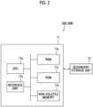
- Fig. 2 is a diagram illustrating an example of a hardware configuration of the information processing unit 100B provided in the server apparatus 200 and the image forming apparatus 100.
- the information processing unit 100B provided in the server apparatus 200 and the image forming apparatus 100 is realized by a computer.
- Each of the server apparatus 200 and the information processing unit 100B includes an arithmetic processing unit 11 that executes a digital arithmetic process according to a program, and a secondary storage unit 12 that stores information.
- the secondary storage unit 12 is realized, for example, by a known information storage device such as a hard disk drive (HDD), a semiconductor memory, or a magnetic tape.
- a hard disk drive HDD
- semiconductor memory a semiconductor memory
- magnetic tape a magnetic tape
- the arithmetic processing unit 11 is provided with a CPU 11a as an example of a processor.
- the arithmetic processing unit 11 is provided with a RAM 11b used as a work memory or the like of the CPU 1 1a and a ROM 11c in which programs or the like executed by the CPU 11a are stored.
- the arithmetic processing unit 11 is provided with a non-volatile memory 11d that is configured to be rewritable and can hold data even in a case in which power supply is interrupted and an interface unit 11e that controls each unit, such as a communication unit, connected to the arithmetic processing unit 11.
- the non-volatile memory 11d is configured by, for example, an SRAM or a flash memory that is backed up by a battery.
- the secondary storage unit 12 stores the programs executed by the arithmetic processing unit 11 in addition to files and the like.
- the arithmetic processing unit 11 reads the program stored in the ROM 11c or the secondary storage unit 12 to perform each process.
- the program executed by the CPU 11a can be provided to the server apparatus 200 and the information processing unit 100B in a state in which the program is stored in a computer-readable recording medium such as a magnetic recording medium (for example, a magnetic tape or a magnetic disk), an optical recording medium (for example, an optical disk), a magnetooptical recording medium, or a semiconductor memory. Further, the program executed by the CPU 11a may be provided to the server apparatus 200 and the information processing unit 100B by a communication unit such as the Internet.
- a computer-readable recording medium such as a magnetic recording medium (for example, a magnetic tape or a magnetic disk), an optical recording medium (for example, an optical disk), a magnetooptical recording medium, or a semiconductor memory.
- the program executed by the CPU 11a may be provided to the server apparatus 200 and the information processing unit 100B by a communication unit such as the Internet.
- processor refers to hardware in a broad sense.
- Examples of the processor include general processors (e.g., CPU: Central Processing Unit) and dedicated processors (e.g., GPU: Graphics Processing Unit, ASIC: Application Specific Integrated Circuit, FPGA: Field Programmable Gate Array, and programmable logic device).
- processor is broad enough to encompass one processor or plural processors in collaboration which are located physically apart from each other but may work cooperatively.
- the order of operations of the processor is not limited to one described in the embodiments above, and may be changed.
- the process executed by the image forming apparatus 100 among the processes described below is executed by the CPU 11a as an example of the processor provided in the image forming apparatus 100.
- the process executed by the server apparatus 200 among the processes described below is executed by the CPU 11a as an example of the processor provided in the server apparatus 200.
- the process for diagnosing the image forming apparatus 100 among the processes described below is executed by the server apparatus 200 as an example of the information processing system.
- the information processing system that executes the process for diagnosing the image forming apparatus 100 may be realized by one apparatus such as one server apparatus 200, or may be realized by a plurality of apparatuses.
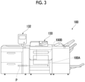
- Fig. 3 is a diagram illustrating the image forming apparatus 100.
- the image forming apparatus 100 is provided with the image forming unit 100A that forms an image on paper P which is an example of a recording medium.
- the paper P passes through the image forming unit 100A in a state where one side of the paper P faces the image forming unit 100A.
- the image forming apparatus 100 is provided with an image reading device 130 as an example of an image reading section that reads an image formed on a recording medium such as paper.
- Such an image reading device 130 is a so-called scanner having a function of transporting the paper.
- the image reading device 130 includes a light source that emits light to paper and a light receiving unit such as a CCD, that receives reflected light from the paper.
- read image data described later is generated based on the reflected light received by the light receiving unit.
- a reading position of an image is set in advance in the image reading device 130, and the image reading device 130 reads an image at a portion of paper that is sequentially transported, which is located at the reading position.
- the image forming apparatus 100 has an information transmission function of transmitting information to the server apparatus 200 (see Fig. 1 ).
- the image reading device 130 is provided above the image forming apparatus 100.
- the image reading device 130 sequentially reads paper (not illustrated) set by the user.
- the paper is not limited to paper on which an image is formed by the image forming apparatus 100, and may be paper on which an image is formed by another image forming apparatus.
- An installation form of the image reading device 130 is not limited to the form illustrated in Fig. 3 .
- the image reading device 130 may be provided inside the image forming apparatus 100 and on a transport path of paper P.
- the paper P on which an image is formed by the image forming unit 100A sequentially passes through the image reading device 130, and at the time of passing through the paper P, each image of the paper P is read in order.
- the image reading device 130 is provided with a paper reversing mechanism so that the paper can be supplied after the front and back sides have been reversed with respect to the reading position of the image.
- the paper on which an image formed on one side is read can be reversed and supplied to the reading position again.
- images on the front and back sides of the paper can be read.
- the paper is placed on a platen (not illustrated) configured by plate-shaped glass or the like so that the paper placed on the platen can be read.
- each image forming apparatus 100 is provided with an operation reception unit 132 that receives an operation from the user.
- the operation reception unit 132 is configured by a so-called touch panel.
- the operation reception unit 132 displays information for the user and receives an operation performed by the user.
- the display of information for the user and the reception of the operation by the user are not limited to being performed by one operation reception unit 132 as in the present exemplary embodiment.
- the operation reception unit and the information display unit may be provided separately.
- the image forming unit 100A is operated to form a chart image on paper P.
- chart paper CP which is the paper on which a chart image being an example of a diagnosis image has been formed is generated.
- a chart image 61 is an image used to diagnose the image forming apparatus 100.
- the chart paper CP which is the paper on which the chart image 61 used for the diagnosis has been formed is generated.
- the chart paper CP is installed on the image reading device 130 as indicated by the reference sign 1B in Fig. 1 .
- the image reading device 130 is used to read the chart paper CP on which the chart image 61 is formed.
- the read image data is transmitted to the server apparatus 200 and then is stored in the server apparatus 200.
- the server apparatus 200 diagnoses the image forming apparatus 100 based on the read image data.
- a user who uses the diagnosis system 1 in the present exemplary embodiment such as a maintainer who maintains the image forming apparatus 100, accesses the server apparatus 200 and refers to the result of the diagnosis by the server apparatus 200.
- each image forming apparatus 100 as described above, the chart paper CP is generated and the chart paper CP is read, and thus the read image data is generated.
- Such read image data is transmitted to the server apparatus 200.
- the server apparatus 200 diagnoses the image forming apparatus 100.
- a diagnosis process executed by the server apparatus 200 will be described.
- the CPU 11a (see Fig. 2 ) as an example of the processor provided in the server apparatus 200 diagnoses the image forming apparatus 100 based on the above-described read image data transmitted from the image forming apparatus 100, and then acquires the diagnosis result which is the result of the diagnosis.
- the CPU 11a acquires a diagnosis result for each of a plurality of diagnostic items, which is a diagnosis result for the chart image 61 that is the image formed on the chart paper CP.
- a plurality of diagnostic items are predetermined.
- the CPU 11a in the server apparatus 200 analyzes the chart image 61 included in the read image data, and acquires a diagnosis result for each of the plurality of diagnostic items.
- the CPU 11a in the server apparatus 200 acquires the diagnosis result for each of the plurality of diagnostic items based on a difference between the reference value predetermined for each of the plurality of diagnostic items and the value obtained by analyzing the chart image 61.
- the CPU 11a in the server apparatus 200 acquires a diagnosis result having a worse evaluation as the difference increases.
- the CPU 11a rearranges the acquired plurality of diagnosis results such that the plurality of acquired diagnosis results are arranged in a predetermined order.
- the CPU 11a rearranges a plurality of diagnosis results such that, for example, the plurality of diagnosis results are arranged in an order of a bad evaluation or a good evaluation.
- the CPU 11a generates a screen in which the plurality of diagnosis results are arranged in a predetermined order.
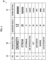
- Fig. 4 is a diagram illustrating an example of a screen 95 generated by the CPU 11a.
- the screen 95 in which a plurality of diagnosis results are arranged in an order of a poor evaluation is illustrated.
- the diagnosis result is indicated by a numerical value, and the smaller the numerical value, the worse the evaluation.
- a plurality of diagnosis results are arranged such that the diagnosis result having a poorer evaluation is located at an upper portion of the screen 95 and the diagnosis result having a better evaluation is located at a lower portion of the screen 95.
- a plurality of diagnosis results may be arranged such that the diagnosis result having a poorer evaluation is located at the lower portion of the screen 95 and the diagnosis result having a better evaluation is located at the upper portion of the screen 95. In this case, a user can easily specify the diagnosis result having a good evaluation.
- information regarding the screen 95 generated by the CPU 11a is transmitted from the server apparatus 200 (see Fig. 1 ) to the user terminal 300, and the screen 95 generated by the CPU 11a is displayed on the user terminal 300.
- the user grasps the diagnosis result for each of a plurality of diagnostic items.
- the present disclosure is not limited to this, and the information regarding the screen 95 may be set to be output to an apparatus having a printing function such as the image forming apparatus 100 (see Fig. 1 ), and the screen 95 may be set to be printed on a recording medium such as paper.
- the "screen 95" is not limited to being displayed on the display device 310, and includes a screen printed on a recording medium such as paper.
- a numerical value (indicated by the reference sign 4A) indicating a rank
- a diagnostic item name indicated by the reference sign 4B
- a coping method indicated by the reference sign 4C are displayed in a state of being associated with each diagnosis result.
- the diagnostic item name can be referred to as information for specifying the diagnostic item.
- a coping method for improving the diagnosis result associated with the selected coping method is displayed.
- a treatment method for this location such as a repair method for a portion of the image forming apparatus 100 that affects the diagnosis result associated with the selected coping method is displayed.
- diagnosis result having a poor evaluation can be referred to as a diagnosis result reflecting a failure or the like of the image forming apparatus 100, and can be referred to as a diagnosis result having a high priority of treatment.
- a plurality of diagnosis results are arranged in a predetermined order, and the display size of the diagnosis results is decreased in accordance with the order. More specifically, on the screen 95 illustrated in Fig. 4 , a plurality of diagnosis results are arranged in an order of a poor evaluation, and the display size of the diagnosis results is decreased in accordance with the order.
- the diagnosis result having a rank closer to the first rank has a larger display size
- the diagnosis result having a rank closer to the last rank has a smaller display size
- the numerical value displayed in the leftmost column indicates the rank. The closer this numerical value is to 1, the larger the display size of the diagnosis result. The closer this numerical value is to 8, the smaller the display size of the diagnosis result.
- Fig. 4 not only the diagnosis result but also the numerical value indicating the rank, the diagnostic item name, and the coping method have different display sizes in accordance with the order.
- the plurality of diagnosis results are arranged in the order of the poor evaluation. Further, on this screen 95, the worse the evaluation, the larger the display size of the diagnosis result.
- the present disclosure is not limited to this, and the screen 95 in which the display size of the diagnosis result increases as the order is lowered may be made.
- the screen 95 illustrated in Fig. 4 in a case where the display size of the diagnosis result becomes larger as the order is lowered, the user can easily specify the diagnosis result having a good evaluation.
- the colors of the diagnosis results are different in accordance with the order of the diagnosis results.
- the color of the diagnosis result having the first rank is red
- the color of the diagnosis result having the second rank is yellow
- the color of the diagnosis result having the third or higher rank is black.
- the numerical value, the diagnostic item name, and the coping method with the first rank has a red color.
- the numerical value, the diagnostic item name, and the coping method with the second rank has a yellow color, and the numerical value, the diagnostic item name, and the coping method with the third or higher rank has a black color.
- Fig. 5 is a diagram illustrating another example of the screen 95 generated by the CPU 11a of the server apparatus 200.
- the user can select a diagnostic item among a plurality of set diagnostic items.
- the diagnosis results for the diagnostic item selected by the user among the plurality of diagnostic items are arranged in a predetermined order.
- Fig. 6 is a diagram illustrating the screen 95 referred in a case where the user selects the diagnostic item.
- the screen 95 illustrated in Fig. 6 is displayed on the user terminal 300 (see Fig. 1 ).
- a plurality of diagnostic items are displayed on the screen 95 illustrated in Fig. 6 , and the user selects a diagnostic item among the plurality of diagnostic items by performing an operation on the user terminal 300.
- the user selects "banding”, “unevenness”, “density”, and “streak”.
- Information regarding the diagnostic item selected by the user is transmitted from the user terminal 300 to the server apparatus 200.
- the CPU 11a of the server apparatus 200 specifies the diagnostic item selected by the user (may be referred to as a "selection diagnostic item" below).
- the CPU 11a of the server apparatus 200 specifies the selection diagnostic item that is the diagnostic item selected by the user.
- the CPU 11a rearranges the plurality of diagnosis results that have already been acquired, based on the specified selection diagnostic item.
- the CPU 11a rearranges the diagnosis results such that the diagnosis results corresponding to the selection diagnostic items are arranged in a predetermined order.
- examples of the predetermined order include an order of a poor evaluation or an order of a good evaluation.
- the CPU 11a does not set the diagnosis result for the diagnostic item other than the selection diagnostic item as a target of the rearrangement, and sets only the diagnosis result for the selection diagnostic item as the target, and then rearranges the diagnosis results.
- the CPU 11a rearranges the diagnosis results by setting, as the target, only the diagnosis results corresponding to the selection diagnostic items among the plurality of diagnosis results that have already been acquired.
- the CPU 11a generates the screen 95.
- the CPU 11a In generating the screen 95, the CPU 11a generates the screen 95 in which the diagnosis results corresponding to the selection diagnostic items are arranged in a predetermined order.
- the CPU 11a in generating the screen 95, the CPU 11a generates the screen 95 in which the diagnosis results corresponding to the selection diagnostic items, which are included in the plurality of diagnosis results that have already been acquired, are arranged in a predetermined order.
- the diagnosis results for each of the above four diagnostic items selected by the user are arranged in a predetermined order. Specifically, on this new screen 95 illustrated in Fig. 5 , the diagnosis results for each of the four diagnostic items are arranged in an order of a poor evaluation.
- the new screen 95 is generated here by rearranging the diagnosis results, the new screen 95 may be generated by another method.
- diagnosis results other than corresponding diagnosis results that are the diagnosis results corresponding to the selection diagnostic items are deleted from the diagnosis results arranged in a predetermined order, which are obtained by the first rearrangement.
- the new screen 95 illustrated in Fig. 5 is generated by displaying only the diagnosis results remaining after the deletion.
- FIG. 7 are diagrams illustrating an example of the new screen 95 generated by the CPU 11a.
- Fig. 8 is a diagram illustrating a relationship between each diagnostic item and a group to which the diagnostic item belongs.
- the screen 95 illustrated in (A) of Fig. 7 illustrates a screen 95 firstly generated by the CPU 11a (referred to as an "initial screen 95" below), and the screen 95 illustrated in (B) of Fig. 7 illustrates a screen 95 that is newly generated by the CPU 11a.
- the screen 95 illustrated in (A) of Fig. 7 illustrates the initial screen 95 obtained by the first rearrangement
- the screen 95 illustrated in (B) of Fig. 7 illustrates a new screen 95 that is generated after the initial screen 95 is generated.
- information regarding a group to which the diagnostic item belongs is associated with each of the plurality of diagnostic items.
- information regarding the diagnostic item and the information regarding the group to which the diagnostic item belongs are associated with each other, and information indicating a relationship between the diagnostic item and the group is generated and registered in advance.
- the information indicating the relationship between the diagnostic item and the group is stored, for example, in the secondary storage unit 12 (see Fig. 2 ) of the server apparatus 200.
- the diagnostic items "density”, “unevenness”, and “banding” belong to the group “natural image quality”, and the group “natural image quality” is associated with the diagnostic items “density”, “unevenness”, and “banding”.
- the diagnostic items "color register” and “line reproduction” belong to the group “text line quality", and the group “text line quality” is associated with the diagnostic items "color register” and "line reproduction”.
- diagnostic items "afterimage”, “streak”, and “dot” belong to the group “image defective quality", and the group “image defective quality” is associated with the diagnostic items “afterimage”, “streak”, and “dot”.
- the CPU 11a rearranges the diagnosis results such that the diagnosis results corresponding to the diagnostic items belonging to the group selected by the user (referred to as a "dependent diagnostic item” below) are arranged in a predetermined order.
- the CPU 11a In generating the new screen 95, the CPU 11a generates the screen 95 in which the diagnosis results corresponding to the dependent diagnostic items are arranged in a predetermined order.
- the screen 95 displayed on the user terminal 300 is switched from the initial screen 95 illustrated in (A) of Fig. 7 to the new screen 95 illustrated in (B) of Fig. 7 .
- a group reception unit 97 for receiving a group selected by the user is provided on the initial screen 95 displayed on the user terminal 300.
- a display in a pull-down format is performed, and the user selects a group by performing an operation on the group reception unit 97.
- the three diagnostic items of "afterimage”, “streak”, and “dot” belong to the group “image defective quality”.
- each of the three diagnostic items of "afterimage”, “streak”, and “dot” is associated with a group to which the name "image defective quality" is associated.
- a new screen 95 in which the diagnosis results for the three diagnostic items of the "afterimage", the "streak", and the "dot" are arranged in a predetermined order is generated.
- examples of the predetermined order include an order of a poor evaluation or an order of a good evaluation.
- Figs. 9 and 10 are diagrams illustrating still another example of the screen 95 generated by the CPU 11a.
- the screen 95 illustrated in Fig. 9 illustrates the initial screen 95 that is firstly generated by the CPU 11a
- the screen 95 illustrated in Fig. 10 illustrates the screen 95 that is newly generated by the CPU 11a.
- the diagnosis result for the diagnostic item designated by the user can be changed based on an instruction from the user.
- a reception display 83 for receiving a change of the diagnosis result is displayed in a state corresponding to each of the diagnosis results.
- the CPU 11a changes the diagnosis result for the diagnostic item designated by the user, based on an instruction from the user who performs an operation on the reception display 83. In other words, the CPU 11a changes the diagnosis result associated with the reception display 83 operated by the user, based on an instruction from the user who performs the operation on the reception display 83.
- the user performs an operation on the reception display 83 to issue an instruction to change the diagnosis result.
- the CPU 11a changes the diagnosis result for the diagnostic item corresponding to the reception display 83 operated by the user, based on the operation amount of the operation performed by the user on the reception display 83.
- each reception display 83 is a display in which the user can move a moving object 83A to the right or left.
- the CPU 11a determines that an instruction has been issued from the user, and that the diagnostic item corresponding to the reception display 83 on which the moving object 83A moved by the user is displayed is the diagnostic item designated by the user.
- the CPU 11a changes the diagnosis result for the diagnostic item designated by the user, based on the movement amount of the moving object 83A.
- the CPU 11a changes the diagnosis result such that the larger the movement amount of the moving object 83A, the larger the change amount of the diagnosis result.
- the CPU 11a changes the diagnosis result such that, as the movement amount of the moving object 83A to the left is increased, the evaluation of the diagnosis result becomes worse, and such that, as the movement amount of the moving object 83A to the right is increased, the evaluation of the diagnosis result becomes better.
- the CPU 11a changes the diagnosis result such that, as the movement amount of the moving object 83A to the left is increased, the numerical value of the diagnosis result becomes smaller, and such that, as the movement amount of the moving object 83A to the right is increased, the numerical value of the diagnosis result becomes larger.
- the CPU 11a rearranges a plurality of diagnosis results including the changed diagnosis result such that the plurality of diagnosis results are arranged in a predetermined order.
- the CPU 11a rearranges a plurality of diagnosis results including the changed diagnosis result such that the plurality of diagnosis results are arranged in a predetermined order.
- the CPU 11a generates a screen 95 in which the plurality of diagnosis results including the changed diagnosis results are arranged in the predetermined order.
- the user moves the moving object 83A on the reception display 83 indicated by the reference sign 9A to the right such that the diagnosis result for the diagnostic item "density" is changed to be improved.
- the user performs an operation on the reception display 83 to input information regarding the strictness of the diagnosis for the diagnostic item designated by the user (referred to as a "designation diagnostic item” below).
- the user inputs information regarding the strictness of the diagnosis for the diagnostic item corresponding to the reception display 83 operated by the user.
- the CPU 11a acquires the information regarding the strictness of the diagnosis. In other words, in this case, the CPU 11a acquires information regarding the strictness of the diagnosis for the designation diagnostic item from the user.
- the CPU 11a acquires information indicating that, as the movement amount of the moving object 83A to the left is increased, the strictness of the diagnosis becomes stricter, and acquires information indicating that, as the movement amount of the moving object 83A to the right is increased, the strictness of the diagnosis becomes less strict.
- the CPU 11a changes the diagnosis result for the designation diagnostic item based on the acquired information regarding the strictness.
- the CPU 11a changes the diagnosis result such that the stricter the strictness specified by the information regarding the strictness, the worse an evaluation of the diagnosis result for the designation diagnostic item, in changing the diagnosis result for the designation diagnostic item.
- the CPU 11a changes the diagnosis result such that the stricter the strictness specified by the information regarding the strictness, the smaller the numerical value of the diagnosis result corresponding to the designation diagnostic item.
- the CPU 11a changes the diagnosis result such that, the stricter the strictness specified by the information regarding the strictness, the smaller the coefficient used in generating the diagnosis result, and thus the evaluation of the diagnosis result becomes worse.
- the CPU 11a changes the diagnosis result such that, the less strict the strictness specified by the information regarding the strictness, the larger the coefficient used in generating the diagnosis result, and thus the evaluation of the diagnosis result becomes better.
- the CPU 11a acquires the diagnosis result by using a predetermined prepared generation expression in the case of acquiring the diagnosis result.
- This generation expression includes a coefficient to be multiplied by the numerical value assigned to this generation expression. In a case where this coefficient is reduced, the numerical value of the diagnosis result becomes small. In a case where this coefficient is increased, the numerical value of the diagnosis result becomes large.
- the CPU 11a changes the diagnosis result such that the stricter the strictness specified by the information regarding the strictness, the smaller the coefficient, and thus the smaller the numerical value of the diagnosis result.
- the CPU 11a changes the diagnosis result such that, the less strict the strictness specified by the information regarding the strictness, the larger the coefficient, and thus the numerical value of the diagnosis result becomes larger.
- the CPU 11a rearranges a plurality of diagnosis results including the diagnosis result for the changed designation diagnostic item such that the plurality of diagnosis results are arranged in the predetermined order described above.
- the CPU 11a generates the new screen 95 in which the plurality of diagnosis results including the changed diagnosis results for the designation diagnostic item are arranged in the predetermined order.
- the screen 95 illustrated in Fig. 10 is generated.
- the numerical value of the diagnosis result for the diagnostic item "density” is a larger value, and the order of the diagnosis result for the diagnostic item "density” is lowered.
- Fig. 11 is a diagram illustrating an example of a process executed by the CPU 11a of the server apparatus 200.
- the CPU 11a acquires the diagnosis result for each of the plurality of diagnostic items, which is the diagnosis result that is the result of diagnosing a chart image 61.
- Fig. 11 8 items of "granular”, “mottle”, “resolution”, “contrast”, “periodic unevenness”, “sudden streak”, “tone jump”, and “text” serve as the diagnostic items, and the CPU 11a acquires the diagnosis result indicated by the reference sign 11A, for each of the plurality of diagnostic items.
- diagnosis result is represented by a numerical value, and the smaller the numerical value, the worse the diagnosis result.
- the CPU 11a first acquires the diagnosis result for each color of cyan, magenta, yellow, and black.
- the CPU 11a acquires each of the diagnosis results indicated by the reference sign 11A, based on the four diagnosis results acquired for each of the colors.
- the image forming unit 100A of the image forming apparatus 100 (see Fig. 1 ) to be diagnosed is provided with four image forming units that form images of different colors. More specifically, the image forming unit 100A is provided with four image forming units that form images of cyan, magenta, yellow, and black, respectively.
- the chart image 61 (see Fig. 1 ) formed on chart paper CP includes an image formed by the four image forming units.
- the CPU 11a analyzes the chart image 61 and acquires the diagnosis result, first, for each color of cyan, magenta, yellow, and black.
- the CPU 11a acquires the diagnosis results for each of the plurality of diagnostic items indicated by the reference sign 11A in Fig. 11 , based on the four diagnosis results acquired for each of the colors.
- the CPU 11a acquires, as the diagnosis result indicated by the reference sign 11A, an average value of the diagnosis results acquired for each color of cyan, magenta, yellow, and black.
- the CPU 11a generates evaluation information for each diagnostic item group that is a group to which each of the diagnostic items indicated by the reference sign 11C belongs, based on the diagnosis result for each diagnostic item belonging to the diagnostic item group.
- the evaluation information is information regarding an evaluation for the diagnostic item group.
- the CPU 11a obtains an average value of diagnosis results for the diagnostic items belonging to the diagnostic item group for each diagnostic item group, and uses this average value as the evaluation information.
- each of "noise”, “sharpness”, “defect”, “gradation”, and “text” indicated by the reference sign 11D serves as the diagnostic item group.
- the numerical value indicated by the reference sign 11E, which is displayed on the right side of the diagnostic item groups serves as the evaluation information.
- the diagnostic items "granular” and “mottle” belong to the diagnostic item group "noise”.
- the CPU 11a generates evaluation information "100" regarding the diagnostic item group "noise”, based on the diagnosis result "100” for the diagnostic item "granular”, and "100” that is the diagnosis result for the diagnostic item "mottle".
- the diagnostic items "resolution” and “contrast” belong to the diagnostic item group "sharpness”.
- the CPU 11a generates evaluation information "80" regarding the diagnostic item group “sharpness”, based on the diagnosis result "90" for the diagnostic item "resolution”, and "70” that is the diagnosis result for the diagnostic item "contrast".
- the diagnostic items "periodic unevenness” and “sudden streak” belong to the diagnostic item group "defect”.
- the CPU 11a generates evaluation information "70" regarding the diagnostic item group "defect", based on the diagnosis result "50" for the diagnostic item "periodic unevenness”, and "90" that is the diagnosis result for the diagnostic item "sudden streak".
- the diagnostic item "tone jump” belongs to the diagnostic item group "gradation”.
- the CPU 11a generates the evaluation information "100" for the diagnostic item group "gradation” based on the diagnosis result "100" for the diagnostic item "tone jump".
- the diagnostic item "text" belongs to the diagnostic item group "text”.
- the CPU 11a generates the evaluation information "100" for the diagnostic item group "text” based on the diagnosis result "100" for the diagnostic item "text”.
- the CPU 11a generates a screen 95 on which each of the diagnostic item groups and the evaluation information corresponding to the diagnostic item group are displayed.
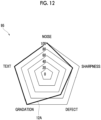
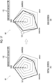
- Fig. 12 is a diagram illustrating an example of the screen 95 generated by the CPU 11a.
- the diagnostic item group and the evaluation information are displayed in a state of being associated with each other.
- the CPU 11a in generating the screen 95, the CPU 11a generates the screen 95 in which each of the diagnostic item groups and the evaluation information are displayed on a graph, as illustrated in Fig. 12 .
- the CPU 11a in generating the screen 95, the CPU 11a generates the screen 95 in which each of the diagnostic item groups and the evaluation information are displayed on a radar chart which is an example of a graph.
- the "graph” refers to a graph showing the relationship between the diagnostic item group and the evaluation information.
- the "radar chart” refers to a chart in which the relationship between the diagnostic item group and the evaluation information is displayed on a polygon.
- the diagnostic item group is associated with each of the vertices of the polygon, and evaluation information of each diagnostic item is displayed on a line connecting the vertex of the polygon and the center of the polygon.
- Figs. 13A and 13B are diagrams illustrating still another example of the screen 95 generated by the CPU 11a of the server apparatus 200.
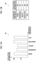
- the screen 95 in which each of the diagnostic item groups and the evaluation information are displayed in a bar graph may be generated.
- the screen 95 in which each of the diagnostic item groups and the evaluation information are displayed in a list format may be generated.
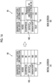
- FIG. 14 are diagrams illustrating screens 95 displayed in a case where the user selects the diagnostic item group.
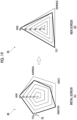
- the screen 95 illustrated in (A) of Fig. 14 illustrates the initial screen 95 which is the screen 95 illustrated in Fig. 12 and is the screen 95 first generated by the CPU 11a.
- the initial screen 95 illustrated in (A) of Fig. 14 illustrates a screen that has already been generated and is displayed on the user terminal 300.
- the CPU 11a generates the new screen 95 illustrated in (B) of Fig. 14 , in which each of the diagnostic items belonging to the diagnostic item group selected by the user and the diagnosis result corresponding to this diagnostic item are additionally displayed on the initial screen 95.
- the CPU 11a generates the new screen 95 on which "periodic unevenness” and “sudden streak” which are diagnostic items belonging to the diagnostic item group "defect" selected by the user and the diagnosis result corresponding to each of "periodic unevenness” and “sudden streak” are additionally displayed.
- the diagnostic items and the diagnosis results additionally displayed are displayed on an additional radar chart 79 (see (B) of Fig. 14 ) that is a radar chart additionally displayed on the basic initial radar chart (see (A) of Fig. 14 ).
- the CPU 11a In a case where the user selects any of the diagnostic item groups, the CPU 11a generates the new screen 95 on which each of the diagnostic items belonging to the diagnostic item group selected by the user and the diagnosis result corresponding to the diagnostic item are additionally displayed on the radar chart that has been displayed so far.
- the CPU 11a may generate the new screen 95 on which each of the diagnostic items belonging to the diagnostic item group selected by the user and the diagnosis result corresponding to the diagnostic item are displayed.
- the CPU 11a generates the new screen 95 on which "periodic unevenness” and “sudden streak” which are diagnostic items belonging to the diagnostic item group "defect" selected by the user and the diagnosis result corresponding to each of "periodic unevenness” and “sudden streak” are displayed.
- FIG. 14 illustrates a case where each of the diagnostic items and the diagnosis result corresponding to the diagnostic item are additionally displayed on the initial screen, but the present disclosure is not limited to this.
- the screen may be changed from the initial screen to another screen.
- Information regarding the diagnostic item group may not be displayed on the other screen, and but each of the diagnostic items belonging to the selected diagnostic item group and the diagnosis result corresponding to the diagnostic item group may be displayed.
- the newly generated screen 95 is transmitted to the user terminal 300 (see Fig. 1 ), and the screen 95 is displayed on the user terminal 300.
- the screen 95 illustrated in (B) of Fig. 14 is displayed on the user terminal 300.
- the diagnostic item belonging to this diagnostic item group and the diagnosis result corresponding to this diagnostic item are displayed.
- FIG. 15 and (A) and (B) of Fig. 16 are diagrams illustrating another display example.
- FIG. 15 illustrate display examples in a case where the diagnostic item group and the evaluation information are displayed by a bar graph and the diagnostic item group is selected by the user.
- the new screen 95 on which a bar graph representing the diagnostic item belonging to this diagnostic item group and the diagnosis result corresponding to the diagnostic item is displayed is generated.
- the bar graph representing the diagnosis result corresponding to the diagnostic item may be displayed inside the display area of the bar graph.
- a bar graph representing the diagnosis result corresponding to the diagnostic item may be displayed on an upper side of a display area of the bar graph while maintaining a state in which the bar graph representing the evaluation information is displayed.
- FIG. 16 illustrate display examples in a case where the diagnostic item group and the evaluation information are displayed in a list format, and the user selects the diagnostic item group.
- a new screen 95 on which the diagnostic items belonging to the diagnostic item group corresponding to this evaluation information and the diagnosis results corresponding to the diagnostic items are displayed may be generated.
- the display form is not limited to this.
- the diagnostic item and the diagnosis result corresponding to the diagnostic item may be displayed in a location different from the display location of the evaluation information, such as the right side of the display location of the evaluation information.
- FIG. 17 are diagrams illustrating another new screen 95 generated by the CPU 11a of the server apparatus 200.
- FIG. 17 illustrates the initial screen 95 generated first by the CPU 11a.
- FIG. 17 illustrates a new screen 95 generated by the CPU 11a.
- the evaluation information may be changed as described later.
- the CPU 11a In a case where the evaluation information is changed, the CPU 11a generates the new screen 95 on which each of the diagnostic item groups and the evaluation information after the change are displayed, as illustrated in (B) of Fig. 17 .
- Fig. 17 illustrates a case where the evaluation information for the diagnostic item group "text" illustrated in (A) of Fig. 17 is changed.
- the CPU 11a generates the new screen 95 on which each of the diagnostic item groups and the evaluation information after the change are displayed, as illustrated in (B) of Fig. 17 .
- FIG. 17 illustrates a case where the evaluation information for the diagnostic item group "text" illustrated in (A) of Fig. 17 is changed from "100" to "80".
- the CPU 11a generates the new screen 95 on which each of the diagnostic item groups and the evaluation information after the change are displayed.
- the evaluation information regarding the diagnostic item group "text" is "80".
- the CPU 11a of the server apparatus 200 generates the evaluation information in accordance with predetermined generation conditions, in generating evaluation information.
- Examples of the generation condition include a generation condition in which the average value of the diagnosis results obtained for each of the dependent diagnostic items that are diagnostic items belonging to the diagnostic item group is used as the evaluation information.
- the CPU 11a uses the average value of the diagnosis results obtained for each of the dependent diagnostic items as the evaluation information for the diagnostic item group.
- the user can input information regarding an item to be emphasized. Further, in the present exemplary embodiment, the generation condition used in generating the evaluation information can be changed.
- the CPU 11a of the server apparatus 200 changes the generation condition and generates new evaluation information by using the changed generation condition. As a result, in this case, the evaluation information is changed.
- the CPU 11a In a case where the generation condition used for generating the evaluation information is changed to a new generation condition, the CPU 11a newly generates the evaluation information for the diagnostic item group by using the new generation condition. Thus, the evaluation information is changed.
- the CPU 11a of the server apparatus 200 generates a new screen 95 on which each of the diagnostic item groups and the newly generated evaluation information are displayed.
- the new screen 95 illustrated in (B) of Fig. 17 is generated.
- the user can use the user terminal 300 (see Fig. 1 ) to input, for example, any one of "emphasis on natural image quality", “emphasis on text line quality”, and "emphasis on image defect" as the item to be emphasized.
- the CPU 11a changes the generation condition set in advance for each diagnostic item group, based on the information regarding this item, which is input by the user.
- the CPU 11a generates new evaluation information for the diagnostic item group by using the changed generation conditions. As a result, as described above, the evaluation information is changed.
- FIG. 17 illustrates the case where the user inputs the item "emphasis on text line quality" as the item to be emphasized, as indicated by the reference sign 17E.
- the CPU 11a of the server apparatus 200 changes the generation condition prepared in advance for the diagnostic item group "text" which is the diagnostic item group associated in advance with this item of "emphasis on text line quality".
- the CPU 11a generates new evaluation information for the diagnostic item group "text" by using the changed generation condition. Accordingly, in this example, the CPU 11a generates new evaluation information of "80" for the diagnostic item group "text".
- the diagnostic item group is associated with each of the items to be emphasized.
- the CPU 11a of the server apparatus 200 changes the generation condition associated with the diagnostic item group associated with the item to be emphasized.
- the CPU 11a changes the generation condition so that the coefficient included in the generation condition becomes small.
- the generation condition in the present exemplary embodiment is configured by a calculation expression including a coefficient to be multiplied by the above-described average value of the diagnosis result of the diagnostic item. Before the change of the generation condition, the coefficient included in this calculation expression is "1".
- the average value of the diagnosis results of the diagnostic items is used as the evaluation information.
- the coefficient is 1, and the average value itself of the diagnosis results of the diagnostic items is generated as the evaluation information.
- the item to be emphasized indicate an item that the user wants the evaluation to be performed strictly.
- the coefficient is reduced.
- the value of the evaluation information is reduced, and the evaluation is output in a stricter form.
- FIG. 18 are diagrams illustrating another example of the new screen 95 generated by the CPU 11a of the server apparatus 200.
- FIG. 18 illustrates the initial screen 95 before the new screen 95 is generated, and (B) of Fig. 18 illustrates the new screen 95.
- the user selects the diagnostic item group from the diagnostic item groups included in the initial screen 95 that is the initial screen 95 generated by the CPU 11a of the server apparatus 200 and is displayed on the user terminal 300. Specifically, the user selects the diagnostic item group by performing an operation on the user terminal 300.
- the CPU 11a generates a new screen 95 on which the diagnostic item group "text" is hidden and the evaluation information corresponding to the diagnostic item group "text" is hidden.
- the CPU 11a selects the diagnostic item group as illustrated in (A) of Fig. 18 , the CPU 11a generates the new screen 95 on which the diagnostic item group selected by the user (referred to as a "selection diagnostic item group" below) is hidden and the evaluation information corresponding to this selection diagnostic item group is hidden, as illustrated in (B) of Fig. 18 .
- Fig. 18 the case where the selection diagnostic item group and the evaluation information corresponding to the selection diagnostic item group are hidden has been described as an example.
- the present disclosure is not limited to this.
- the selection diagnostic item group and the evaluation information corresponding to this selection diagnostic item group may be made inconspicuous by reducing the display density of the selection diagnostic item group and the evaluation information corresponding to this selection diagnostic item group.
- the CPU 11a may generate the new screen 95 on which the selection diagnostic item group that is the diagnostic item group selected by the user is displayed, and other diagnostic item groups are hidden.
- the CPU 11a may generate the new screen 95 on which the non-selection diagnostic item group that is the diagnostic item group other than the selection diagnostic item group is hidden, and the evaluation information corresponding to this non-selection diagnostic item group is hidden.
- FIG. 19 are diagrams illustrating still another example of the new screen 95 generated by the CPU 11a. Similar to the above description, (A) of Fig. 19 illustrates the initial screen 95 before the new screen 95 is generated, and (B) of Fig. 19 illustrates the new screen 95.
- FIG. 19 illustrates a case where the user selects three diagnostic item groups of "text”, “noise”, and “sharpness” from the diagnostic item groups displayed in (A) of Fig. 19 .
- the CPU 11a of the server apparatus 200 generates the new screen 95 on which the non-selection diagnostic item groups "defect” and "gradation” that are the diagnostic item groups other than "text", “noise”, and “sharpness” are hidden, and the evaluation information corresponding to the non-selection diagnostic item group is hidden.
- the non-selection diagnostic item group and the evaluation information corresponding to this non-selection diagnostic item group may be made inconspicuous by reducing the display density of the non-selection diagnostic item group and the evaluation information corresponding to this non-selection diagnostic item group.
Landscapes
- Engineering & Computer Science (AREA)
- Health & Medical Sciences (AREA)
- Biomedical Technology (AREA)
- General Health & Medical Sciences (AREA)
- Multimedia (AREA)
- Signal Processing (AREA)
- Physics & Mathematics (AREA)
- General Physics & Mathematics (AREA)
- Theoretical Computer Science (AREA)
- Human Computer Interaction (AREA)
- Facsimiles In General (AREA)
- Control Or Security For Electrophotography (AREA)
Abstract
Description
- The present invention relates to an information processing system, a program, and an information processing method.
- In
JP2020-149531A -
JP2015-76009A - Diagnosis may be performed on an image formed on a recording medium by an image forming apparatus, and a screen displaying a result of this diagnosis may be generated.
- Here, in a case where the display position of the diagnosis result is fixed and does not change, for example, a situation in which a result of which a user is to be preferentially notified is buried in other results, and it is difficult to notify the user of the result of which a user is to be preferentially notified may occur.
- An object of the present invention is to easily notify a user of a result of diagnosing an image formed on a recording medium, as compared with a case where a display position of the result of diagnosing the image formed on the recording medium is fixed and does not change.
- According to a first aspect of the present disclosure, there is provided an information processing system including a processor configured to acquire a diagnosis result for each of a plurality of diagnostic items, the diagnosis result being a result of diagnosing an image formed on a recording medium, rearrange the acquired plurality of diagnosis results such that the plurality of diagnosis results are arranged in a predetermined order, and generate a screen in which the plurality of diagnosis results are arranged in the predetermined order.
- According to a second aspect of the present disclosure, there is provided an information processing system according to the first aspect, in which the processor may be configured to rearrange the plurality of diagnosis results such that the plurality of diagnosis results are arranged in an order of a poor evaluation or a good evaluation, in rearranging the plurality of diagnosis results.
- According to a third aspect of the present disclosure, there is provided an information processing system according to the first or second aspect, in which the processor may be configured to generate the screen in which the plurality of diagnosis results are arranged in the predetermined order and a display size of each of the diagnosis results is increased or decreased in accordance with the order, in generating the screen.
- According to a fourth aspect of the present disclosure, there is provided an information processing system according to the third aspect, in which the processor may be configured to generate the screen in which the diagnosis result having a rank closer to a first rank has a larger display size, and the diagnosis result having a rank closer to a last rank has a smaller display size, in generating the screen.
- According to a fifth aspect of the present disclosure, there is provided an information processing system according to the first aspect, in which the processor may be configured to rearrange the plurality of diagnosis results such that the plurality of diagnosis results are arranged in an order of a poor evaluation, in rearranging the plurality of diagnosis results, and generate the screen in which the plurality of diagnosis results are arranged in the order of the poor evaluation and the diagnosis result having a poorer evaluation has a larger display size, in generating the screen.
- According to a sixth aspect of the present disclosure, there is provided an information processing system according to the first aspect, in which the processor may be configured to rearrange the plurality of diagnosis results such that the plurality of diagnosis results are arranged in an order of a poor evaluation, in rearranging the plurality of diagnosis results, and generate the screen in which the diagnosis result having a poorer evaluation is located at an upper portion of the screen and the diagnosis result having a better evaluation is located at a lower portion of the screen, in generating the screen.
- According to a seventh aspect of the present disclosure, there is provided an information processing system according to any one of the first to sixth aspects, in which the processor may be configured to generate the screen in which the plurality of diagnosis results are arranged in the predetermined order and a color of each of the diagnosis results is different in accordance with the order, in generating the screen.
- According to an eighth aspect of the present disclosure, there is provided an information processing system according to any one of the first to seventh aspects, in which the processor may be configured to specify a selection diagnostic item that is the diagnostic item selected by a user among the plurality of diagnostic items, rearrange the diagnosis result corresponding to the selection diagnostic item such that the diagnosis result is arranged in the predetermined order, in rearranging the plurality of diagnosis results, and generate the screen in which the diagnosis result corresponding to the selection diagnostic item is arranged in the predetermined order, in generating the screen.
- According to a ninth aspect of the present disclosure, there is provided an information processing system according to any one of the first to seventh aspects, in which information regarding a group to which the diagnostic item belongs may be associated with each of the plurality of diagnostic items, and the processor may be configured to rearrange the diagnosis result corresponding to a dependent diagnostic item that is the diagnostic item belonging to a group selected by a user such that the diagnosis result is arranged in the predetermined order, in rearranging the plurality of diagnosis results, and generate the screen in which the diagnosis result corresponding to the dependent diagnostic item is arranged in the predetermined order, in generating the screen.
- According to a tenth aspect of the present disclosure, there is provided an information processing system according to the first aspect, in which the processor may be configured to change the diagnosis result for the diagnostic item designated by a user based on an instruction from the user, in a case where the diagnosis result is changed by the user, rearrange a plurality of diagnosis results including the changed diagnosis result such that the plurality of diagnosis results are arranged in the predetermined order, and generate the screen in which the plurality of diagnosis results including the changed diagnosis result are arranged in the predetermined order.
- According to an eleventh aspect of the present disclosure, there is provided an information processing system according to the first aspect, in which the processor may be configured to acquire information regarding strictness of diagnosis for a designation diagnostic item that is the diagnostic item designated by a user, from the user, change the diagnosis result for the designation diagnostic item based on the acquired information regarding the strictness, rearrange a plurality of diagnosis results including the changed diagnosis result for the designation diagnostic item such that the plurality of diagnosis results are arranged in the predetermined order, and generate the screen in which the plurality of diagnosis results including the changed diagnosis result for the designation diagnostic item are arranged in the predetermined order.
- According to a twelfth aspect of the present disclosure, there is provided an information processing system according to the eleventh aspect, in which the processor may be configured to change the diagnosis result such that the stricter the strictness specified by the information regarding the strictness, the worse an evaluation of the diagnosis result for the designation diagnostic item, in changing the diagnosis result for the designation diagnostic item.
- According to a thirteenth aspect of the present disclosure, there is provided a program causing a computer to realize a function of acquiring a diagnosis result for each of a plurality of diagnostic items, the diagnosis result being a result of diagnosing an image formed on a recording medium, a function of rearranging the acquired plurality of diagnosis results such that the plurality of diagnosis results are arranged in a predetermined order, and a function of generating a screen in which the plurality of diagnosis results are arranged in the predetermined order.
- According to a fourteenth aspect of the present disclosure, there is provided an information processing method including acquiring a diagnosis result for each of a plurality of diagnostic items, the diagnosis result being a result of diagnosing an image formed on a recording medium, rearranging the acquired plurality of diagnosis results such that the plurality of diagnosis results are arranged in a predetermined order, and generating a screen in which the plurality of diagnosis results are arranged in the predetermined order.
- According to the first aspect of the present disclosure, it is possible to easily notify a user of a result of diagnosing an image formed on a recording medium, as compared with a case where a display position of the result of diagnosing the image formed on the recording medium is fixed and does not change.
- According to the second aspect of the present disclosure, it is possible to rearrange a plurality of diagnosis results such that the plurality of diagnosis results are arranged in an order of a poor evaluation or a good evaluation.
- According to the third aspect of the present disclosure, it is possible to generate a screen in which a plurality of diagnosis results are arranged in a predetermined order and the display size of each of the diagnosis results is increased or decreased in accordance with the order.
- According to the fourth aspect of the present disclosure, it is possible to generate a screen in which a diagnosis result having a rank closer to a first rank has a larger display size, and a diagnosis result having a rank closer to a last rank has a smaller display size.
- According to the fifth aspect of the present disclosure, it is possible to generate a screen in which a plurality of diagnosis results are arranged in an order of a poor evaluation and the diagnosis result having a poorer evaluation has a larger display size.
- According to the sixth aspect of the present disclosure, it is possible to generate a screen in which a diagnosis result having a poorer evaluation is located at an upper portion of the screen and a diagnosis result having a better evaluation is located at a lower portion of the screen.
- According to the seventh aspect of the present disclosure, it is possible to generate a screen in which a plurality of diagnosis results are arranged in a predetermined order and a color of each of the diagnosis results is different in accordance with the order.
- According to the eighth aspect of the present disclosure, it is possible to generate a screen in which a diagnosis result corresponding to a selection diagnostic item that is a diagnostic item selected by a user is arranged in a predetermined order.
- According to the ninth aspect of the present disclosure, it is possible to generate a screen in which a diagnosis result corresponding to a dependent diagnostic item that is a diagnostic item belonging to a group selected by a user is arranged in a predetermined order.
- According to the tenth aspect of the present disclosure, it is possible to generate a screen in which a plurality of diagnosis results including a diagnosis result changed by a user are arranged in a predetermined order.
- According to the eleventh aspect of the present disclosure, it is possible to generate a screen in which a plurality of diagnosis results including a diagnosis result changed based on information regarding strictness of diagnosis are arranged in a predetermined order.
- According to the twelfth aspect of the present disclosure, it is possible to set an evaluation of a diagnosis result for a designation diagnostic item that is a diagnostic item designated by a user to become worse as strictness specified by information regarding strictness of diagnosis becomes stricter.
- According to the thirteenth aspect of the present disclosure, it is possible to easily notify a user of a result of diagnosing an image formed on a recording medium, as compared with a case where a display position of the result of diagnosing the image formed on the recording medium is fixed and does not change.
- According to the fourteenth aspect of the present disclosure, it is possible to easily notify a user of a result of diagnosing an image formed on a recording medium, as compared with a case where a display position of the result of diagnosing the image formed on the recording medium is fixed and does not change.
- Exemplary embodiment(s) of the present invention will be described in detail based on the following figures, wherein:
-
Fig. 1 is a diagram illustrating an example of a diagnosis system; -
Fig. 2 is a diagram illustrating an example of a hardware configuration of an information processing unit provided in a server apparatus and an image forming apparatus; -
Fig. 3 is a diagram illustrating an image forming apparatus; -
Fig. 4 is a diagram illustrating an example of a screen generated by a CPU; -
Fig. 5 is a diagram illustrating another example of the screen generated by the CPU of the server apparatus; -
Fig. 6 is a diagram illustrating a screen referred in a case where a user selects a diagnostic item;
(A) and (B) ofFig. 7 are diagrams illustrating an example of a new screen generated by the CPU; -
Fig. 8 is a diagram illustrating a relationship between each diagnostic item and a group to which the diagnostic item belongs; -
Fig. 9 is a diagram illustrating still another example of the screen generated by the CPU; -
Fig. 10 is a diagram illustrating still yet another example of the screen generated by the CPU; -
Fig. 11 is a diagram illustrating an example of a process executed by the CPU of the server apparatus; -
Fig. 12 is a diagram illustrating still yet another example of the screen generated by the CPU; -
Figs. 13A and 13B are diagrams illustrating still another example of the screen generated by the CPU of the server apparatus;- (A) and (B) of
Fig. 14 are diagrams illustrating screens displayed in a case where the user selects a diagnostic item group; - (A) and (B) of
Fig. 15 are diagrams illustrating another display example; - (A) and (B) of
Fig. 16 are diagrams illustrating still another display example; - (A) and (B) of
Fig. 17 are diagrams illustrating another new screen generated by the CPU of the server apparatus; - (A) and (B) of
Fig. 18 are diagrams illustrating another example of the new screen generated by the CPU of the server apparatus; and - (A) and (B) of
Fig. 19 are diagrams illustrating still another example of the new screen generated by the CPU.
- (A) and (B) of
- Hereinafter, an exemplary embodiment of the present invention will be described with reference to the accompanying drawings.
-
Fig. 1 is a diagram illustrating an example of adiagnosis system 1. - The
diagnosis system 1 according to the present exemplary embodiment is provided with a plurality ofimage forming apparatuses 100 and aserver apparatus 200 that is connected to each of the plurality ofimage forming apparatuses 100 via acommunication line 190. In the present exemplary embodiment, in theserver apparatus 200 as an example of an information processing system, diagnosis of eachimage forming apparatus 100 is performed. - Further, the
diagnosis system 1 in the present exemplary embodiment is provided with auser terminal 300 that is connected to theserver apparatus 200 and receives an operation from a user. - In
Fig. 1 , oneimage forming apparatus 100 among a plurality ofimage forming apparatuses 100 is displayed. - The
user terminal 300 is provided with adisplay device 310. Theuser terminal 300 is realized by a computer. Examples of the form of theuser terminal 300 include a personal computer (PC), a smartphone, and a tablet terminal. - The
image forming apparatus 100 is provided with animage forming unit 100A as an example of an image forming section that forms an image on paper which is an example of a recording medium. - For example, the formation of an image on paper by the
image forming unit 100A is performed by an inkjet method or an electrophotographic method. In addition, the formation of an image on paper by theimage forming unit 100A is not limited to the inkjet method or the electrophotographic method, but may be performed by other methods. - The
image forming apparatus 100 is further provided with aninformation processing unit 100B. Theinformation processing unit 100B executes various processes executed in theimage forming apparatus 100. -
Fig. 2 is a diagram illustrating an example of a hardware configuration of theinformation processing unit 100B provided in theserver apparatus 200 and theimage forming apparatus 100. Theinformation processing unit 100B provided in theserver apparatus 200 and theimage forming apparatus 100 is realized by a computer. - Each of the
server apparatus 200 and theinformation processing unit 100B includes anarithmetic processing unit 11 that executes a digital arithmetic process according to a program, and asecondary storage unit 12 that stores information. - The
secondary storage unit 12 is realized, for example, by a known information storage device such as a hard disk drive (HDD), a semiconductor memory, or a magnetic tape. - The
arithmetic processing unit 11 is provided with aCPU 11a as an example of a processor. - In addition, the
arithmetic processing unit 11 is provided with aRAM 11b used as a work memory or the like of theCPU 1 1a and aROM 11c in which programs or the like executed by theCPU 11a are stored. - In addition, the
arithmetic processing unit 11 is provided with anon-volatile memory 11d that is configured to be rewritable and can hold data even in a case in which power supply is interrupted and aninterface unit 11e that controls each unit, such as a communication unit, connected to thearithmetic processing unit 11. - The
non-volatile memory 11d is configured by, for example, an SRAM or a flash memory that is backed up by a battery. Thesecondary storage unit 12 stores the programs executed by thearithmetic processing unit 11 in addition to files and the like. - In the present exemplary embodiment, the
arithmetic processing unit 11 reads the program stored in theROM 11c or thesecondary storage unit 12 to perform each process. - The program executed by the
CPU 11a can be provided to theserver apparatus 200 and theinformation processing unit 100B in a state in which the program is stored in a computer-readable recording medium such as a magnetic recording medium (for example, a magnetic tape or a magnetic disk), an optical recording medium (for example, an optical disk), a magnetooptical recording medium, or a semiconductor memory. Further, the program executed by theCPU 11a may be provided to theserver apparatus 200 and theinformation processing unit 100B by a communication unit such as the Internet. - In the embodiments above, the term "processor" refers to hardware in a broad sense. Examples of the processor include general processors (e.g., CPU: Central Processing Unit) and dedicated processors (e.g., GPU: Graphics Processing Unit, ASIC: Application Specific Integrated Circuit, FPGA: Field Programmable Gate Array, and programmable logic device).
- In the embodiments above, the term "processor" is broad enough to encompass one processor or plural processors in collaboration which are located physically apart from each other but may work cooperatively. The order of operations of the processor is not limited to one described in the embodiments above, and may be changed.
- The process executed by the
image forming apparatus 100 among the processes described below is executed by theCPU 11a as an example of the processor provided in theimage forming apparatus 100. - The process executed by the
server apparatus 200 among the processes described below is executed by theCPU 11a as an example of the processor provided in theserver apparatus 200. - Further, the process for diagnosing the
image forming apparatus 100 among the processes described below is executed by theserver apparatus 200 as an example of the information processing system. The information processing system that executes the process for diagnosing theimage forming apparatus 100 may be realized by one apparatus such as oneserver apparatus 200, or may be realized by a plurality of apparatuses. -
Fig. 3 is a diagram illustrating theimage forming apparatus 100. - In the present exemplary embodiment, as described above, the
image forming apparatus 100 is provided with theimage forming unit 100A that forms an image on paper P which is an example of a recording medium. - In the present exemplary embodiment, in a case where the paper P passes through the
image forming unit 100A, the paper P passes through theimage forming unit 100A in a state where one side of the paper P faces theimage forming unit 100A. - Further, the
image forming apparatus 100 is provided with animage reading device 130 as an example of an image reading section that reads an image formed on a recording medium such as paper. - Such an
image reading device 130 is a so-called scanner having a function of transporting the paper. Theimage reading device 130 includes a light source that emits light to paper and a light receiving unit such as a CCD, that receives reflected light from the paper. In the present exemplary embodiment, read image data described later is generated based on the reflected light received by the light receiving unit. - A reading position of an image is set in advance in the
image reading device 130, and theimage reading device 130 reads an image at a portion of paper that is sequentially transported, which is located at the reading position. - The
image forming apparatus 100 has an information transmission function of transmitting information to the server apparatus 200 (seeFig. 1 ). - In the example illustrated in
Fig. 3 , theimage reading device 130 is provided above theimage forming apparatus 100. Theimage reading device 130 sequentially reads paper (not illustrated) set by the user. The paper is not limited to paper on which an image is formed by theimage forming apparatus 100, and may be paper on which an image is formed by another image forming apparatus. - An installation form of the
image reading device 130 is not limited to the form illustrated inFig. 3 . Theimage reading device 130 may be provided inside theimage forming apparatus 100 and on a transport path of paper P. - In this case, the paper P on which an image is formed by the
image forming unit 100A sequentially passes through theimage reading device 130, and at the time of passing through the paper P, each image of the paper P is read in order. - In the present exemplary embodiment, the
image reading device 130 is provided with a paper reversing mechanism so that the paper can be supplied after the front and back sides have been reversed with respect to the reading position of the image. - Thus, in the present exemplary embodiment, the paper on which an image formed on one side is read can be reversed and supplied to the reading position again. As a result, images on the front and back sides of the paper can be read.
- In addition, in reading an image on paper, the paper is placed on a platen (not illustrated) configured by plate-shaped glass or the like so that the paper placed on the platen can be read.
- Further, each
image forming apparatus 100 is provided with anoperation reception unit 132 that receives an operation from the user. Theoperation reception unit 132 is configured by a so-called touch panel. Theoperation reception unit 132 displays information for the user and receives an operation performed by the user. - The display of information for the user and the reception of the operation by the user are not limited to being performed by one
operation reception unit 132 as in the present exemplary embodiment. The operation reception unit and the information display unit may be provided separately. - In the present exemplary embodiment, in a case in which the image forming apparatus 100 (see
Fig. 1 ) is diagnosed, first, theimage forming unit 100A is operated to form a chart image on paper P. Thus, as indicated by thereference sign 1A inFig. 1 , chart paper CP which is the paper on which a chart image being an example of a diagnosis image has been formed is generated. - A
chart image 61 is an image used to diagnose theimage forming apparatus 100. In the present exemplary embodiment, the chart paper CP which is the paper on which thechart image 61 used for the diagnosis has been formed is generated. - In a case where the chart paper CP is generated, the chart paper CP is installed on the
image reading device 130 as indicated by thereference sign 1B inFig. 1 . Theimage reading device 130 is used to read the chart paper CP on which thechart image 61 is formed. - As a result, read image data obtained by reading the chart paper CP is generated.
- In the present exemplary embodiment, the read image data is transmitted to the
server apparatus 200 and then is stored in theserver apparatus 200. Theserver apparatus 200 diagnoses theimage forming apparatus 100 based on the read image data. - In the present exemplary embodiment, a user who uses the
diagnosis system 1 in the present exemplary embodiment, such as a maintainer who maintains theimage forming apparatus 100, accesses theserver apparatus 200 and refers to the result of the diagnosis by theserver apparatus 200. - In each
image forming apparatus 100, as described above, the chart paper CP is generated and the chart paper CP is read, and thus the read image data is generated. - Such read image data is transmitted to the
server apparatus 200. As described above, in the present exemplary embodiment, theserver apparatus 200 diagnoses theimage forming apparatus 100. - A diagnosis process executed by the
server apparatus 200 will be described. - In the present exemplary embodiment, the
CPU 11a (seeFig. 2 ) as an example of the processor provided in theserver apparatus 200 diagnoses theimage forming apparatus 100 based on the above-described read image data transmitted from theimage forming apparatus 100, and then acquires the diagnosis result which is the result of the diagnosis. - More specifically, the
CPU 11a acquires a diagnosis result for each of a plurality of diagnostic items, which is a diagnosis result for thechart image 61 that is the image formed on the chart paper CP. - In the present exemplary embodiment, a plurality of diagnostic items are predetermined. The
CPU 11a in theserver apparatus 200 analyzes thechart image 61 included in the read image data, and acquires a diagnosis result for each of the plurality of diagnostic items. - More specifically, for example, the
CPU 11a in theserver apparatus 200 acquires the diagnosis result for each of the plurality of diagnostic items based on a difference between the reference value predetermined for each of the plurality of diagnostic items and the value obtained by analyzing thechart image 61. - The
CPU 11a in theserver apparatus 200 acquires a diagnosis result having a worse evaluation as the difference increases. - Then, the
CPU 11a rearranges the acquired plurality of diagnosis results such that the plurality of acquired diagnosis results are arranged in a predetermined order. - More specifically, in rearranging the plurality of diagnosis results, the
CPU 11a rearranges a plurality of diagnosis results such that, for example, the plurality of diagnosis results are arranged in an order of a bad evaluation or a good evaluation. - Then, the
CPU 11a generates a screen in which the plurality of diagnosis results are arranged in a predetermined order. -
Fig. 4 is a diagram illustrating an example of ascreen 95 generated by theCPU 11a. - In this example illustrated in
Fig. 4 , thescreen 95 in which a plurality of diagnosis results are arranged in an order of a poor evaluation is illustrated. In the present exemplary embodiment, the diagnosis result is indicated by a numerical value, and the smaller the numerical value, the worse the evaluation. - In the example illustrated in
Fig. 4 , a plurality of diagnosis results are arranged such that the diagnosis result having a poorer evaluation is located at an upper portion of thescreen 95 and the diagnosis result having a better evaluation is located at a lower portion of thescreen 95. - In addition, a plurality of diagnosis results may be arranged such that the diagnosis result having a poorer evaluation is located at the lower portion of the
screen 95 and the diagnosis result having a better evaluation is located at the upper portion of thescreen 95. In this case, a user can easily specify the diagnosis result having a good evaluation. - In the present exemplary embodiment, information regarding the
screen 95 generated by theCPU 11a is transmitted from the server apparatus 200 (seeFig. 1 ) to theuser terminal 300, and thescreen 95 generated by theCPU 11a is displayed on theuser terminal 300. As a result, the user grasps the diagnosis result for each of a plurality of diagnostic items. - The present disclosure is not limited to this, and the information regarding the
screen 95 may be set to be output to an apparatus having a printing function such as the image forming apparatus 100 (seeFig. 1 ), and thescreen 95 may be set to be printed on a recording medium such as paper. - The "
screen 95" is not limited to being displayed on thedisplay device 310, and includes a screen printed on a recording medium such as paper. - In the
screen 95 illustrated inFig. 4 , in addition to the diagnosis result, a numerical value (indicated by thereference sign 4A) indicating a rank, a diagnostic item name indicated by thereference sign 4B, and a coping method indicated by thereference sign 4C are displayed in a state of being associated with each diagnosis result. Here, the diagnostic item name can be referred to as information for specifying the diagnostic item. - In the present exemplary embodiment, in a case where the user selects a display location of the coping method on the
screen 95 illustrated inFig. 4 , a coping method for improving the diagnosis result associated with the selected coping method is displayed. - In other words, in a case where the user selects the display location of a coping method, a treatment method for this location, such as a repair method for a portion of the
image forming apparatus 100 that affects the diagnosis result associated with the selected coping method is displayed. - Here, the diagnosis result having a poor evaluation can be referred to as a diagnosis result reflecting a failure or the like of the
image forming apparatus 100, and can be referred to as a diagnosis result having a high priority of treatment. - On the
screen 95 illustrated inFig. 4 , a plurality of diagnosis results are arranged in a predetermined order, and the display size of the diagnosis results is decreased in accordance with the order. More specifically, on thescreen 95 illustrated inFig. 4 , a plurality of diagnosis results are arranged in an order of a poor evaluation, and the display size of the diagnosis results is decreased in accordance with the order. - In other words, on this
screen 95 illustrated inFig. 4 , the diagnosis result having a rank closer to the first rank has a larger display size, and the diagnosis result having a rank closer to the last rank has a smaller display size. - On this
screen 95 illustrated inFig. 4 , the numerical value displayed in the leftmost column indicates the rank. The closer this numerical value is to 1, the larger the display size of the diagnosis result. The closer this numerical value is to 8, the smaller the display size of the diagnosis result. - In
Fig. 4 , not only the diagnosis result but also the numerical value indicating the rank, the diagnostic item name, and the coping method have different display sizes in accordance with the order. - As described above, on this
screen 95 illustrated inFig. 4 , the plurality of diagnosis results are arranged in the order of the poor evaluation. Further, on thisscreen 95, the worse the evaluation, the larger the display size of the diagnosis result. - The present disclosure is not limited to this, and the
screen 95 in which the display size of the diagnosis result increases as the order is lowered may be made. On thescreen 95 illustrated inFig. 4 , in a case where the display size of the diagnosis result becomes larger as the order is lowered, the user can easily specify the diagnosis result having a good evaluation. - Further, on the
screen 95 illustrated inFig. 4 , the colors of the diagnosis results are different in accordance with the order of the diagnosis results. - Specifically, on the
screen 95 illustrated inFig. 4 , the color of the diagnosis result having the first rank is red, and the color of the diagnosis result having the second rank is yellow. The color of the diagnosis result having the third or higher rank is black. - Not only the diagnosis result, but also the numerical value indicating the rank, the diagnostic item name, and the coping method are different in color in accordance with the order.
- Similar to the diagnosis result, the numerical value, the diagnostic item name, and the coping method with the first rank has a red color. The numerical value, the diagnostic item name, and the coping method with the second rank has a yellow color, and the numerical value, the diagnostic item name, and the coping method with the third or higher rank has a black color.
-
Fig. 5 is a diagram illustrating another example of thescreen 95 generated by theCPU 11a of theserver apparatus 200. - In the example illustrated in
Fig. 5 , the diagnosis results for some of the above-described plurality of diagnostic items are displayed. - In the present exemplary embodiment, the user can select a diagnostic item among a plurality of set diagnostic items. In
Fig. 5 , the diagnosis results for the diagnostic item selected by the user among the plurality of diagnostic items are arranged in a predetermined order. -
Fig. 6 is a diagram illustrating thescreen 95 referred in a case where the user selects the diagnostic item. - In the present exemplary embodiment, the
screen 95 illustrated inFig. 6 is displayed on the user terminal 300 (seeFig. 1 ). - A plurality of diagnostic items are displayed on the
screen 95 illustrated inFig. 6 , and the user selects a diagnostic item among the plurality of diagnostic items by performing an operation on theuser terminal 300. In this example, the user selects "banding", "unevenness", "density", and "streak". - Information regarding the diagnostic item selected by the user is transmitted from the
user terminal 300 to theserver apparatus 200. - Accordingly, the
CPU 11a of theserver apparatus 200 specifies the diagnostic item selected by the user (may be referred to as a "selection diagnostic item" below). In the present exemplary embodiment, in a case where the user selects a diagnostic item, theCPU 11a of theserver apparatus 200 specifies the selection diagnostic item that is the diagnostic item selected by the user. - The
CPU 11a rearranges the plurality of diagnosis results that have already been acquired, based on the specified selection diagnostic item. - In this rearrangement, the
CPU 11a rearranges the diagnosis results such that the diagnosis results corresponding to the selection diagnostic items are arranged in a predetermined order. Here, similar to the above description, examples of the predetermined order include an order of a poor evaluation or an order of a good evaluation. - In other words, in this case, the
CPU 11a does not set the diagnosis result for the diagnostic item other than the selection diagnostic item as a target of the rearrangement, and sets only the diagnosis result for the selection diagnostic item as the target, and then rearranges the diagnosis results. - In other words, in this case, the
CPU 11a rearranges the diagnosis results by setting, as the target, only the diagnosis results corresponding to the selection diagnostic items among the plurality of diagnosis results that have already been acquired. - Then, the
CPU 11a generates thescreen 95. In generating thescreen 95, theCPU 11a generates thescreen 95 in which the diagnosis results corresponding to the selection diagnostic items are arranged in a predetermined order. - In other words, in generating the
screen 95, theCPU 11a generates thescreen 95 in which the diagnosis results corresponding to the selection diagnostic items, which are included in the plurality of diagnosis results that have already been acquired, are arranged in a predetermined order. - As a result, a
new screen 95 illustrated inFig. 5 is generated. - In the
new screen 95 illustrated inFig. 5 , the diagnosis results for each of the above four diagnostic items selected by the user are arranged in a predetermined order. Specifically, on thisnew screen 95 illustrated inFig. 5 , the diagnosis results for each of the four diagnostic items are arranged in an order of a poor evaluation. - Although the
new screen 95 is generated here by rearranging the diagnosis results, thenew screen 95 may be generated by another method. - For example, the diagnosis results other than corresponding diagnosis results that are the diagnosis results corresponding to the selection diagnostic items, are deleted from the diagnosis results arranged in a predetermined order, which are obtained by the first rearrangement. The
new screen 95 illustrated inFig. 5 is generated by displaying only the diagnosis results remaining after the deletion. - (A) and (B) of
Fig. 7 are diagrams illustrating an example of thenew screen 95 generated by theCPU 11a.Fig. 8 is a diagram illustrating a relationship between each diagnostic item and a group to which the diagnostic item belongs. - The
screen 95 illustrated in (A) ofFig. 7 illustrates ascreen 95 firstly generated by theCPU 11a (referred to as an "initial screen 95" below), and thescreen 95 illustrated in (B) ofFig. 7 illustrates ascreen 95 that is newly generated by theCPU 11a. - In other words, the
screen 95 illustrated in (A) ofFig. 7 illustrates theinitial screen 95 obtained by the first rearrangement, and thescreen 95 illustrated in (B) ofFig. 7 illustrates anew screen 95 that is generated after theinitial screen 95 is generated. - As illustrated in (B) of
Fig. 7 , in this example as well, on the newly generatedscreen 95, the diagnosis results for some of the above-described plurality of diagnostic items are displayed. - In the present exemplary embodiment, as illustrated in
Fig. 8 , information regarding a group to which the diagnostic item belongs is associated with each of the plurality of diagnostic items. - In the present exemplary embodiment, information regarding the diagnostic item and the information regarding the group to which the diagnostic item belongs are associated with each other, and information indicating a relationship between the diagnostic item and the group is generated and registered in advance. The information indicating the relationship between the diagnostic item and the group is stored, for example, in the secondary storage unit 12 (see
Fig. 2 ) of theserver apparatus 200. - In the example illustrated in
Fig. 8 , the diagnostic items "density", "unevenness", and "banding" belong to the group "natural image quality", and the group "natural image quality" is associated with the diagnostic items "density", "unevenness", and "banding". - The diagnostic items "color register" and "line reproduction" belong to the group "text line quality", and the group "text line quality" is associated with the diagnostic items "color register" and "line reproduction".
- In addition, the diagnostic items "afterimage", "streak", and "dot" belong to the group "image defective quality", and the group "image defective quality" is associated with the diagnostic items "afterimage", "streak", and "dot".
- Here, a process example in a case where the user selects one group from the plurality of groups will be described.
- In a case where the user selects a group, the
CPU 11a rearranges the diagnosis results such that the diagnosis results corresponding to the diagnostic items belonging to the group selected by the user (referred to as a "dependent diagnostic item" below) are arranged in a predetermined order. - In generating the
new screen 95, theCPU 11a generates thescreen 95 in which the diagnosis results corresponding to the dependent diagnostic items are arranged in a predetermined order. - As a result, the
new screen 95 illustrated in (B) ofFig. 7 is generated. - In the present exemplary embodiment, in a case where the user selects a group, the
screen 95 displayed on theuser terminal 300 is switched from theinitial screen 95 illustrated in (A) ofFig. 7 to thenew screen 95 illustrated in (B) ofFig. 7 . - In this example, as indicated by the reference sign 7Ain (A) of
Fig. 7 , agroup reception unit 97 for receiving a group selected by the user is provided on theinitial screen 95 displayed on theuser terminal 300. In thegroup reception unit 97, a display in a pull-down format is performed, and the user selects a group by performing an operation on thegroup reception unit 97. - In the example illustrated in (A) of
Fig. 7 , a case where the group "image defective quality" is selected as an example of the group by the user is illustrated. - In this case, as illustrated in (B) of
Fig. 7 , thenew screen 95 in which the diagnosis results for three diagnostic items of "afterimage", "streak", and "dot" are arranged in a predetermined order is generated. - Here, as described above, the three diagnostic items of "afterimage", "streak", and "dot" belong to the group "image defective quality". In other words, each of the three diagnostic items of "afterimage", "streak", and "dot" is associated with a group to which the name "image defective quality" is associated.
- In this case, as described above, a
new screen 95 in which the diagnosis results for the three diagnostic items of the "afterimage", the "streak", and the "dot" are arranged in a predetermined order is generated. Here, similar to the above description, examples of the predetermined order include an order of a poor evaluation or an order of a good evaluation. -
Figs. 9 and10 are diagrams illustrating still another example of thescreen 95 generated by theCPU 11a. - The
screen 95 illustrated inFig. 9 illustrates theinitial screen 95 that is firstly generated by theCPU 11a, and thescreen 95 illustrated inFig. 10 illustrates thescreen 95 that is newly generated by theCPU 11a. - In this example, the diagnosis result for the diagnostic item designated by the user can be changed based on an instruction from the user.
- Specifically, on the
screen 95 illustrated inFig. 9 , areception display 83 for receiving a change of the diagnosis result is displayed in a state corresponding to each of the diagnosis results. - The
CPU 11a changes the diagnosis result for the diagnostic item designated by the user, based on an instruction from the user who performs an operation on thereception display 83. In other words, theCPU 11a changes the diagnosis result associated with thereception display 83 operated by the user, based on an instruction from the user who performs the operation on thereception display 83. - The user performs an operation on the
reception display 83 to issue an instruction to change the diagnosis result. - In response to this instruction, the
CPU 11a changes the diagnosis result for the diagnostic item corresponding to thereception display 83 operated by the user, based on the operation amount of the operation performed by the user on thereception display 83. - Here, each
reception display 83 is a display in which the user can move a movingobject 83A to the right or left. - In a case where the moving
object 83A is moved, theCPU 11a determines that an instruction has been issued from the user, and that the diagnostic item corresponding to thereception display 83 on which the movingobject 83A moved by the user is displayed is the diagnostic item designated by the user. - The
CPU 11a changes the diagnosis result for the diagnostic item designated by the user, based on the movement amount of the movingobject 83A. TheCPU 11a changes the diagnosis result such that the larger the movement amount of the movingobject 83A, the larger the change amount of the diagnosis result. - More specifically, in this example, the
CPU 11a changes the diagnosis result such that, as the movement amount of the movingobject 83A to the left is increased, the evaluation of the diagnosis result becomes worse, and such that, as the movement amount of the movingobject 83A to the right is increased, the evaluation of the diagnosis result becomes better. - More specifically, the
CPU 11a changes the diagnosis result such that, as the movement amount of the movingobject 83A to the left is increased, the numerical value of the diagnosis result becomes smaller, and such that, as the movement amount of the movingobject 83A to the right is increased, the numerical value of the diagnosis result becomes larger. - Then, the
CPU 11a rearranges a plurality of diagnosis results including the changed diagnosis result such that the plurality of diagnosis results are arranged in a predetermined order. - In other words, in a case where the diagnosis result is changed by the user, the
CPU 11a rearranges a plurality of diagnosis results including the changed diagnosis result such that the plurality of diagnosis results are arranged in a predetermined order. - Then, as illustrated in
Fig. 10 , theCPU 11a generates ascreen 95 in which the plurality of diagnosis results including the changed diagnosis results are arranged in the predetermined order. - Specifically, for example, in this example, a case where the user performs an operation on the
reception display 83 indicated by thereference sign 9A inFig. 9 , and changes the diagnosis result for the diagnostic item "density" that is the diagnostic item designated by the user will be described. - More specifically, in this example, the user moves the moving
object 83A on thereception display 83 indicated by thereference sign 9A to the right such that the diagnosis result for the diagnostic item "density" is changed to be improved. - In this case, as illustrated in
Fig. 10 , on the newly generatedscreen 95, the rank of the diagnosis result for the "density" is lowered, and thus the diagnosis result for the "density" is displayed at the lower rank. - The
screen 95 illustrated inFig. 9 will be further described. - In the
screen 95 illustrated inFig. 9 , the user performs an operation on thereception display 83 to input information regarding the strictness of the diagnosis for the diagnostic item designated by the user (referred to as a "designation diagnostic item" below). - In other words, the user inputs information regarding the strictness of the diagnosis for the diagnostic item corresponding to the
reception display 83 operated by the user. - In a case where the operation on the
reception display 83 is performed, theCPU 11a acquires the information regarding the strictness of the diagnosis. In other words, in this case, theCPU 11a acquires information regarding the strictness of the diagnosis for the designation diagnostic item from the user. - More specifically, the
CPU 11a acquires information indicating that, as the movement amount of the movingobject 83A to the left is increased, the strictness of the diagnosis becomes stricter, and acquires information indicating that, as the movement amount of the movingobject 83A to the right is increased, the strictness of the diagnosis becomes less strict. - The
CPU 11a changes the diagnosis result for the designation diagnostic item based on the acquired information regarding the strictness. - Here, the
CPU 11a changes the diagnosis result such that the stricter the strictness specified by the information regarding the strictness, the worse an evaluation of the diagnosis result for the designation diagnostic item, in changing the diagnosis result for the designation diagnostic item. - Specifically, the
CPU 11a changes the diagnosis result such that the stricter the strictness specified by the information regarding the strictness, the smaller the numerical value of the diagnosis result corresponding to the designation diagnostic item. - More specifically, the
CPU 11a changes the diagnosis result such that, the stricter the strictness specified by the information regarding the strictness, the smaller the coefficient used in generating the diagnosis result, and thus the evaluation of the diagnosis result becomes worse. - Further, the
CPU 11a changes the diagnosis result such that, the less strict the strictness specified by the information regarding the strictness, the larger the coefficient used in generating the diagnosis result, and thus the evaluation of the diagnosis result becomes better. - Although the description has been omitted above, the
CPU 11a acquires the diagnosis result by using a predetermined prepared generation expression in the case of acquiring the diagnosis result. - This generation expression includes a coefficient to be multiplied by the numerical value assigned to this generation expression. In a case where this coefficient is reduced, the numerical value of the diagnosis result becomes small. In a case where this coefficient is increased, the numerical value of the diagnosis result becomes large.
- The
CPU 11a changes the diagnosis result such that the stricter the strictness specified by the information regarding the strictness, the smaller the coefficient, and thus the smaller the numerical value of the diagnosis result. - Further, the
CPU 11a changes the diagnosis result such that, the less strict the strictness specified by the information regarding the strictness, the larger the coefficient, and thus the numerical value of the diagnosis result becomes larger. - The
CPU 11a rearranges a plurality of diagnosis results including the diagnosis result for the changed designation diagnostic item such that the plurality of diagnosis results are arranged in the predetermined order described above. - The
CPU 11a generates thenew screen 95 in which the plurality of diagnosis results including the changed diagnosis results for the designation diagnostic item are arranged in the predetermined order. Thus, for example, thescreen 95 illustrated inFig. 10 is generated. - In this
screen 95 illustrated inFig. 10 , the numerical value of the diagnosis result for the diagnostic item "density" is a larger value, and the order of the diagnosis result for the diagnostic item "density" is lowered. -
Fig. 11 is a diagram illustrating an example of a process executed by theCPU 11a of theserver apparatus 200. - Also in this process example, first, the
CPU 11a acquires the diagnosis result for each of the plurality of diagnostic items, which is the diagnosis result that is the result of diagnosing achart image 61. - Specifically, in this example illustrated in
Fig. 11 ,8 items of "granular", "mottle", "resolution", "contrast", "periodic unevenness", "sudden streak", "tone jump", and "text" serve as the diagnostic items, and theCPU 11a acquires the diagnosis result indicated by thereference sign 11A, for each of the plurality of diagnostic items. - Here, the diagnosis result is represented by a numerical value, and the smaller the numerical value, the worse the diagnosis result.
- More specifically, as indicated by the
reference sign 11B inFig. 11 , theCPU 11a first acquires the diagnosis result for each color of cyan, magenta, yellow, and black. TheCPU 11a acquires each of the diagnosis results indicated by thereference sign 11A, based on the four diagnosis results acquired for each of the colors. - Although not described above, the
image forming unit 100A of the image forming apparatus 100 (seeFig. 1 ) to be diagnosed is provided with four image forming units that form images of different colors. More specifically, theimage forming unit 100A is provided with four image forming units that form images of cyan, magenta, yellow, and black, respectively. - The chart image 61 (see
Fig. 1 ) formed on chart paper CP includes an image formed by the four image forming units. TheCPU 11a analyzes thechart image 61 and acquires the diagnosis result, first, for each color of cyan, magenta, yellow, and black. - The
CPU 11a acquires the diagnosis results for each of the plurality of diagnostic items indicated by thereference sign 11A inFig. 11 , based on the four diagnosis results acquired for each of the colors. - Here, the
CPU 11a acquires, as the diagnosis result indicated by thereference sign 11A, an average value of the diagnosis results acquired for each color of cyan, magenta, yellow, and black. - Then, in this example, the
CPU 11a generates evaluation information for each diagnostic item group that is a group to which each of the diagnostic items indicated by the reference sign 11C belongs, based on the diagnosis result for each diagnostic item belonging to the diagnostic item group. The evaluation information is information regarding an evaluation for the diagnostic item group. - Specifically, the
CPU 11a obtains an average value of diagnosis results for the diagnostic items belonging to the diagnostic item group for each diagnostic item group, and uses this average value as the evaluation information. - In the example illustrated in
Fig. 11 , each of "noise", "sharpness", "defect", "gradation", and "text" indicated by thereference sign 11D serves as the diagnostic item group. - Further, in the example illustrated in
Fig. 11 , the numerical value indicated by thereference sign 11E, which is displayed on the right side of the diagnostic item groups serves as the evaluation information. - In this example, the diagnostic items "granular" and "mottle" belong to the diagnostic item group "noise".
- In this case, the
CPU 11a generates evaluation information "100" regarding the diagnostic item group "noise", based on the diagnosis result "100" for the diagnostic item "granular", and "100" that is the diagnosis result for the diagnostic item "mottle". - Further, in this example, the diagnostic items "resolution" and "contrast" belong to the diagnostic item group "sharpness".
- In this case, the
CPU 11a generates evaluation information "80" regarding the diagnostic item group "sharpness", based on the diagnosis result "90" for the diagnostic item "resolution", and "70" that is the diagnosis result for the diagnostic item "contrast". - Further, in this example, the diagnostic items "periodic unevenness" and "sudden streak" belong to the diagnostic item group "defect".
- In this case, the
CPU 11a generates evaluation information "70" regarding the diagnostic item group "defect", based on the diagnosis result "50" for the diagnostic item "periodic unevenness", and "90" that is the diagnosis result for the diagnostic item "sudden streak". - Further, in this example, the diagnostic item "tone jump" belongs to the diagnostic item group "gradation".
- In this case, the
CPU 11a generates the evaluation information "100" for the diagnostic item group "gradation" based on the diagnosis result "100" for the diagnostic item "tone jump". - Further, in this example, the diagnostic item "text" belongs to the diagnostic item group "text".
- In this case, the
CPU 11a generates the evaluation information "100" for the diagnostic item group "text" based on the diagnosis result "100" for the diagnostic item "text". - Then, the
CPU 11a generates ascreen 95 on which each of the diagnostic item groups and the evaluation information corresponding to the diagnostic item group are displayed. -
Fig. 12 is a diagram illustrating an example of thescreen 95 generated by theCPU 11a. - On this
screen 95, five diagnostic item groups of "noise", "sharpness", "defect", "gradation", and "text", which are diagnostic item groups, are displayed, and further, the evaluation information corresponding to the five diagnostic item groups is displayed. Here, the evaluation information is represented by the positions of the vertices of the pentagon indicated by thereference sign 12A. - On this
screen 95, the diagnostic item group and the evaluation information are displayed in a state of being associated with each other. - In this example, in generating the
screen 95, theCPU 11a generates thescreen 95 in which each of the diagnostic item groups and the evaluation information are displayed on a graph, as illustrated inFig. 12 . - More specifically, in this example, in generating the
screen 95, theCPU 11a generates thescreen 95 in which each of the diagnostic item groups and the evaluation information are displayed on a radar chart which is an example of a graph. - Here, the "graph" refers to a graph showing the relationship between the diagnostic item group and the evaluation information.
- Further, the "radar chart" refers to a chart in which the relationship between the diagnostic item group and the evaluation information is displayed on a polygon. In the present exemplary embodiment, the diagnostic item group is associated with each of the vertices of the polygon, and evaluation information of each diagnostic item is displayed on a line connecting the vertex of the polygon and the center of the polygon.
-
Figs. 13A and 13B are diagrams illustrating still another example of thescreen 95 generated by theCPU 11a of theserver apparatus 200. - In the above description, a case where the diagnostic item group and the evaluation information are displayed on the radar chart has been described as an example, but the graph is not limited to the radar chart.
- As illustrated in
Fig. 13A , thescreen 95 in which each of the diagnostic item groups and the evaluation information are displayed in a bar graph may be generated. - Further, as illustrated in
Fig. 13B , for example, thescreen 95 in which each of the diagnostic item groups and the evaluation information are displayed in a list format may be generated. - (A) and (B) of
Fig. 14 arediagrams illustrating screens 95 displayed in a case where the user selects the diagnostic item group. - The
screen 95 illustrated in (A) ofFig. 14 illustrates theinitial screen 95 which is thescreen 95 illustrated inFig. 12 and is thescreen 95 first generated by theCPU 11a. Theinitial screen 95 illustrated in (A) ofFig. 14 illustrates a screen that has already been generated and is displayed on theuser terminal 300. - In this process example illustrated in
Fig. 14 , it is assumed that the user selects the diagnostic item group from the diagnostic item groups included in theinitial screen 95 illustrated in (A) ofFig. 14 . - Specifically, in this example, it is assumed that the user moves a
cursor 78 to a display location of the diagnostic item group "defect" and selects the diagnostic item group "defect" from a plurality of diagnostic item groups. - In this case, the
CPU 11a generates thenew screen 95 illustrated in (B) ofFig. 14 , in which each of the diagnostic items belonging to the diagnostic item group selected by the user and the diagnosis result corresponding to this diagnostic item are additionally displayed on theinitial screen 95. - Specifically, in this example, the
CPU 11a generates thenew screen 95 on which "periodic unevenness" and "sudden streak" which are diagnostic items belonging to the diagnostic item group "defect" selected by the user and the diagnosis result corresponding to each of "periodic unevenness" and "sudden streak" are additionally displayed. - In this example, the diagnostic items and the diagnosis results additionally displayed are displayed on an additional radar chart 79 (see (B) of
Fig. 14 ) that is a radar chart additionally displayed on the basic initial radar chart (see (A) ofFig. 14 ). - In a case where the user selects any of the diagnostic item groups, the
CPU 11a generates thenew screen 95 on which each of the diagnostic items belonging to the diagnostic item group selected by the user and the diagnosis result corresponding to the diagnostic item are additionally displayed on the radar chart that has been displayed so far. - Here, "additionally displayed on the radar chart that has been displayed so far" means not that the diagnostic item and the diagnosis result are displayed inside an outer peripheral edge 74 (see (A) of
Fig. 14 ) of the initial radar chart, but that the diagnostic item and the diagnosis result are additionally displayed on theinitial screen 95 on which the radar chart is displayed. - In addition, the
CPU 11a may generate thenew screen 95 on which each of the diagnostic items belonging to the diagnostic item group selected by the user and the diagnosis result corresponding to the diagnostic item are displayed. - Specifically, in this example, the
CPU 11a generates thenew screen 95 on which "periodic unevenness" and "sudden streak" which are diagnostic items belonging to the diagnostic item group "defect" selected by the user and the diagnosis result corresponding to each of "periodic unevenness" and "sudden streak" are displayed. - (B) of
Fig. 14 illustrates a case where each of the diagnostic items and the diagnosis result corresponding to the diagnostic item are additionally displayed on the initial screen, but the present disclosure is not limited to this. After the diagnostic item group is selected, the screen may be changed from the initial screen to another screen. Information regarding the diagnostic item group may not be displayed on the other screen, and but each of the diagnostic items belonging to the selected diagnostic item group and the diagnosis result corresponding to the diagnostic item group may be displayed. - In the example illustrated in
Fig. 14 , for example, as illustrated in (A) ofFig. 14 , in a case where the user moves thecursor 78 to the diagnostic item group and mouse-overs the diagnostic item group, theCPU 11a generates thenew screen 95 illustrated in (B) ofFig. 14 . - The newly generated
screen 95 is transmitted to the user terminal 300 (seeFig. 1 ), and thescreen 95 is displayed on theuser terminal 300. Thus, thescreen 95 illustrated in (B) ofFig. 14 is displayed on theuser terminal 300. - In this process example, in a case where the diagnostic item group is selected by the user, detailed information regarding the diagnostic item group is displayed.
- Specifically, as detailed information, the diagnostic item belonging to this diagnostic item group and the diagnosis result corresponding to this diagnostic item are displayed.
- Although not illustrated, in a case where an evaluation item included in the newly generated
screen 95 illustrated in (B) ofFig. 14 is selected, four diagnosis results acquired for each of the above colors may be additionally displayed. - (A) and (B) of
Fig. 15 and (A) and (B) ofFig. 16 are diagrams illustrating another display example. - (A) and (B) of
Fig. 15 illustrate display examples in a case where the diagnostic item group and the evaluation information are displayed by a bar graph and the diagnostic item group is selected by the user. - In a case where the
initial screen 95 illustrated in (A) ofFig. 15 is displayed, for example, in a case where the user selects the diagnostic item group indicated by thereference sign 15E, as illustrated in (B) ofFig. 15 , thenew screen 95 on which a bar graph representing the diagnostic item belonging to this diagnostic item group and the diagnosis result corresponding to the diagnostic item is displayed is generated. - In this
new screen 95 illustrated in (B) ofFig. 15 , the bar graph representing the evaluation information corresponding to the diagnostic item group selected by the user is deleted, and a bar graph representing the diagnosis result corresponding to the diagnostic item is displayed at a location in which the deleted bar graph has been displayed. - The case where the bar graph representing the evaluation information is deleted and the bar graph representing the diagnosis result corresponding to the diagnostic item is displayed has been described here, but the display form is not limited to this.
- While maintaining the state in which the bar graph representing the evaluation information is displayed, for example, the bar graph representing the diagnosis result corresponding to the diagnostic item may be displayed inside the display area of the bar graph.
- In addition, for example, a bar graph representing the diagnosis result corresponding to the diagnostic item may be displayed on an upper side of a display area of the bar graph while maintaining a state in which the bar graph representing the evaluation information is displayed.
- (A) and (B) of
Fig. 16 illustrate display examples in a case where the diagnostic item group and the evaluation information are displayed in a list format, and the user selects the diagnostic item group. - In this example, in a state where the
initial screen 95 illustrated in (A) ofFig. 16 is displayed, in a case where the user moves thecursor 78 to, for example, a display location of the diagnostic item group indicated by thereference sign 16E, and selects the diagnostic item group, thenew screen 95 illustrated in (B) ofFig. 16 is generated. - In this
new screen 95 illustrated in (B) ofFig. 16 , the diagnostic item belonging to this diagnostic item group and the diagnosis result corresponding to this diagnostic item are displayed at a location in which the evaluation information corresponding to the diagnostic item group selected by the user is displayed. - In the example illustrated in
Fig. 16 , the case where, in a case where the user selects the diagnostic item group, thenew screen 95 on which the diagnostic items belonging to the diagnostic item group and the diagnosis results corresponding to the diagnostic items are displayed is generated will be described. - The present disclosure is not limited to this. In a case where the user moves the
cursor 78 to the display location of the evaluation information and selects the evaluation information in the case where the screen in (A) ofFig. 16 is displayed, anew screen 95 on which the diagnostic items belonging to the diagnostic item group corresponding to this evaluation information and the diagnosis results corresponding to the diagnostic items are displayed may be generated. - Further, in the example illustrated in
Fig. 16 , as illustrated in (B) ofFig. 16 , the case where the diagnostic item belonging to the diagnostic item group and the diagnosis result corresponding to the diagnostic item are displayed in a location in which the evaluation information has been displayed has been described. - The display form is not limited to this. The diagnostic item and the diagnosis result corresponding to the diagnostic item may be displayed in a location different from the display location of the evaluation information, such as the right side of the display location of the evaluation information.
- (A) and (B) of
Fig. 17 are diagrams illustrating anothernew screen 95 generated by theCPU 11a of theserver apparatus 200. - (A) of
Fig. 17 illustrates theinitial screen 95 generated first by theCPU 11a. (B) ofFig. 17 illustrates anew screen 95 generated by theCPU 11a. - In the present exemplary embodiment, the evaluation information may be changed as described later.
- In a case where the evaluation information is changed, the
CPU 11a generates thenew screen 95 on which each of the diagnostic item groups and the evaluation information after the change are displayed, as illustrated in (B) ofFig. 17 . - Specifically, the example illustrated in
Fig. 17 illustrates a case where the evaluation information for the diagnostic item group "text" illustrated in (A) ofFig. 17 is changed. In this case, theCPU 11a generates thenew screen 95 on which each of the diagnostic item groups and the evaluation information after the change are displayed, as illustrated in (B) ofFig. 17 . - More specifically, the example illustrated in (A) and (B) of
Fig. 17 illustrates a case where the evaluation information for the diagnostic item group "text" illustrated in (A) ofFig. 17 is changed from "100" to "80". - In this case, as illustrated in (B) of
Fig. 17 , theCPU 11a generates thenew screen 95 on which each of the diagnostic item groups and the evaluation information after the change are displayed. On thisnew screen 95, the evaluation information regarding the diagnostic item group "text" is "80". - In the example illustrated in (A) and (B) of
Fig. 17 , only the evaluation information for the diagnostic item group "text" is changed. On thenew screen 95 illustrated in (B) ofFig. 17 , the evaluation information regarding the diagnostic item group "text" is changed, and the evaluation information regarding the diagnostic item group other than "text" is not changed. - In the present exemplary embodiment, the
CPU 11a of theserver apparatus 200 generates the evaluation information in accordance with predetermined generation conditions, in generating evaluation information. - Examples of the generation condition include a generation condition in which the average value of the diagnosis results obtained for each of the dependent diagnostic items that are diagnostic items belonging to the diagnostic item group is used as the evaluation information.
- In this case, the
CPU 11a uses the average value of the diagnosis results obtained for each of the dependent diagnostic items as the evaluation information for the diagnostic item group. - Further, in the present exemplary embodiment, the user can input information regarding an item to be emphasized. Further, in the present exemplary embodiment, the generation condition used in generating the evaluation information can be changed.
- In the present exemplary embodiment, in a case where the item to be emphasized is input, the
CPU 11a of theserver apparatus 200 changes the generation condition and generates new evaluation information by using the changed generation condition. As a result, in this case, the evaluation information is changed. - In a case where the generation condition used for generating the evaluation information is changed to a new generation condition, the
CPU 11a newly generates the evaluation information for the diagnostic item group by using the new generation condition. Thus, the evaluation information is changed. - In this case, as described above, the
CPU 11a of theserver apparatus 200 generates anew screen 95 on which each of the diagnostic item groups and the newly generated evaluation information are displayed. As a result, thenew screen 95 illustrated in (B) ofFig. 17 is generated. - Specifically, in the present exemplary embodiment, the user can use the user terminal 300 (see
Fig. 1 ) to input, for example, any one of "emphasis on natural image quality", "emphasis on text line quality", and "emphasis on image defect" as the item to be emphasized. - In a case where information regarding any of the above items is input, the
CPU 11a changes the generation condition set in advance for each diagnostic item group, based on the information regarding this item, which is input by the user. - The
CPU 11a generates new evaluation information for the diagnostic item group by using the changed generation conditions. As a result, as described above, the evaluation information is changed. - (A) of
Fig. 17 illustrates the case where the user inputs the item "emphasis on text line quality" as the item to be emphasized, as indicated by thereference sign 17E. - In this case, the
CPU 11a of theserver apparatus 200 changes the generation condition prepared in advance for the diagnostic item group "text" which is the diagnostic item group associated in advance with this item of "emphasis on text line quality". - The
CPU 11a generates new evaluation information for the diagnostic item group "text" by using the changed generation condition. Accordingly, in this example, theCPU 11a generates new evaluation information of "80" for the diagnostic item group "text". - In the present exemplary embodiment, the diagnostic item group is associated with each of the items to be emphasized.
- In the present exemplary embodiment, in a case where the item to be emphasized is input, the
CPU 11a of theserver apparatus 200 changes the generation condition associated with the diagnostic item group associated with the item to be emphasized. - Specifically, the
CPU 11a changes the generation condition so that the coefficient included in the generation condition becomes small. The generation condition in the present exemplary embodiment is configured by a calculation expression including a coefficient to be multiplied by the above-described average value of the diagnosis result of the diagnostic item. Before the change of the generation condition, the coefficient included in this calculation expression is "1". - In the present exemplary embodiment, as described above, the average value of the diagnosis results of the diagnostic items is used as the evaluation information. However, in a normal case, the coefficient is 1, and the average value itself of the diagnosis results of the diagnostic items is generated as the evaluation information.
- On the other hand, in a case where the generation condition is changed so that the coefficient included in the generation condition becomes small, the coefficient having a value smaller than 1 is multiplied by the above average value. In a case where the generation condition is changed, the value of the newly generated evaluation information is reduced.
- Here, the item to be emphasized indicate an item that the user wants the evaluation to be performed strictly. In the present exemplary embodiment, in a case where the user inputs information regarding any of the items as described above, as a result, the coefficient is reduced. Thus, the value of the evaluation information is reduced, and the evaluation is output in a stricter form.
- (A) and (B) of
Fig. 18 are diagrams illustrating another example of thenew screen 95 generated by theCPU 11a of theserver apparatus 200. - (A) of
Fig. 18 illustrates theinitial screen 95 before thenew screen 95 is generated, and (B) ofFig. 18 illustrates thenew screen 95. - In this example, the user selects the diagnostic item group from the diagnostic item groups included in the
initial screen 95 that is theinitial screen 95 generated by theCPU 11a of theserver apparatus 200 and is displayed on theuser terminal 300. Specifically, the user selects the diagnostic item group by performing an operation on theuser terminal 300. - In this process example, as illustrated in (A) of
Fig. 18 , the user moves thecursor 78 to a display location of the diagnostic item group "text", and selects the diagnostic item group "text" from a plurality of diagnostic item groups. - In this case, as illustrated in (B) of
Fig. 18 , theCPU 11a generates anew screen 95 on which the diagnostic item group "text" is hidden and the evaluation information corresponding to the diagnostic item group "text" is hidden. - In this process example, in a case where the
CPU 11a selects the diagnostic item group as illustrated in (A) ofFig. 18 , theCPU 11a generates thenew screen 95 on which the diagnostic item group selected by the user (referred to as a "selection diagnostic item group" below) is hidden and the evaluation information corresponding to this selection diagnostic item group is hidden, as illustrated in (B) ofFig. 18 . - In
Fig. 18 , the case where the selection diagnostic item group and the evaluation information corresponding to the selection diagnostic item group are hidden has been described as an example. The present disclosure is not limited to this. The selection diagnostic item group and the evaluation information corresponding to this selection diagnostic item group may be made inconspicuous by reducing the display density of the selection diagnostic item group and the evaluation information corresponding to this selection diagnostic item group. - In addition, in a case where the user selects the diagnostic item group from the diagnostic item group displayed on the
initial screen 95 first generated, theCPU 11a may generate thenew screen 95 on which the selection diagnostic item group that is the diagnostic item group selected by the user is displayed, and other diagnostic item groups are hidden. - Specifically, in this case, the
CPU 11a may generate thenew screen 95 on which the non-selection diagnostic item group that is the diagnostic item group other than the selection diagnostic item group is hidden, and the evaluation information corresponding to this non-selection diagnostic item group is hidden. - (A) and (B) of
Fig. 19 are diagrams illustrating still another example of thenew screen 95 generated by theCPU 11a. Similar to the above description, (A) ofFig. 19 illustrates theinitial screen 95 before thenew screen 95 is generated, and (B) ofFig. 19 illustrates thenew screen 95. - This example illustrated in
Fig. 19 illustrates a case where the user selects three diagnostic item groups of "text", "noise", and "sharpness" from the diagnostic item groups displayed in (A) ofFig. 19 . - In this case, as illustrated in (B) of
Fig. 19 , theCPU 11a of theserver apparatus 200 generates thenew screen 95 on which the non-selection diagnostic item groups "defect" and "gradation" that are the diagnostic item groups other than "text", "noise", and "sharpness" are hidden, and the evaluation information corresponding to the non-selection diagnostic item group is hidden. - Similar to the above description, the non-selection diagnostic item group and the evaluation information corresponding to this non-selection diagnostic item group may be made inconspicuous by reducing the display density of the non-selection diagnostic item group and the evaluation information corresponding to this non-selection diagnostic item group.
-
- (((1))) An information processing system comprising:
a processor configured to:- acquire a diagnosis result for each of a plurality of diagnostic items, the diagnosis result being a result of diagnosing an image formed on a recording medium;
- rearrange the acquired plurality of diagnosis results such that the plurality of diagnosis results are arranged in a predetermined order; and
- generate a screen in which the plurality of diagnosis results are arranged in the predetermined order.
- (((2))) The information processing system according to (((1))), wherein the processor is configured to:
rearrange the plurality of diagnosis results such that the plurality of diagnosis results are arranged in an order of a poor evaluation or a good evaluation, in rearranging the plurality of diagnosis results. - (((3))) The information processing system according to (((1))) or (((2))), wherein the processor is configured to:
generate the screen in which the plurality of diagnosis results are arranged in the predetermined order and a display size of each of the diagnosis results is increased or decreased in accordance with the order, in generating the screen. - (((4))) The information processing system according to (((3))), wherein the processor is configured to:
generate the screen in which the diagnosis result having a rank closer to a first rank has a larger display size, and the diagnosis result having a rank closer to a last rank has a smaller display size, in generating the screen. - (((5))) The information processing system according to (((1))), wherein the processor is configured to:
- rearrange the plurality of diagnosis results such that the plurality of diagnosis results are arranged in an order of a poor evaluation, in rearranging the plurality of diagnosis results; and
- generate the screen in which the plurality of diagnosis results are arranged in the order of the poor evaluation and the diagnosis result having a poorer evaluation has a larger display size, in generating the screen.
- (((6))) The information processing system according to (((1))), wherein the processor is configured to:
- rearrange the plurality of diagnosis results such that the plurality of diagnosis results are arranged in an order of a poor evaluation, in rearranging the plurality of diagnosis results; and
- generate the screen in which the diagnosis result having a poorer evaluation is located at an upper portion of the screen and the diagnosis result having a better evaluation is located at a lower portion of the screen, in generating the screen.
- (((7))) The information processing system according to any one of (((1))) to (((6))), wherein the processor is configured to:
generate the screen in which the plurality of diagnosis results are arranged in the predetermined order and a color of each of the diagnosis results is different in accordance with the order, in generating the screen. - (((8))) The information processing system according to any one of (((1))) to (((7))), wherein the processor is configured to:
- specify a selection diagnostic item that is the diagnostic item selected by a user among the plurality of diagnostic items;
- rearrange the diagnosis result corresponding to the selection diagnostic item such that the diagnosis result is arranged in the predetermined order, in rearranging the plurality of diagnosis results; and
- generate the screen in which the diagnosis result corresponding to the selection diagnostic item is arranged in the predetermined order, in generating the screen.
- (((9))) The information processing system according to any one of (((1))) to (((7))),
- wherein information regarding a group to which the diagnostic item belongs is associated with each of the plurality of diagnostic items, and
- the processor is configured to:
- rearrange the diagnosis result corresponding to a dependent diagnostic item that is the diagnostic item belonging to a group selected by a user such that the diagnosis result is arranged in the predetermined order, in rearranging the plurality of diagnosis results; and
- generate the screen in which the diagnosis result corresponding to the dependent diagnostic item is arranged in the predetermined order, in generating the screen.
- (((10))) The information processing system according to (((1))), wherein the processor is configured to:
- change the diagnosis result for the diagnostic item designated by a user based on an instruction from the user;
- in a case where the diagnosis result is changed by the user, rearrange a plurality of diagnosis results including the changed diagnosis result such that the plurality of diagnosis results are arranged in the predetermined order; and
- generate the screen in which the plurality of diagnosis results including the changed diagnosis result are arranged in the predetermined order.
- (((11))) The information processing system according to (((1))), wherein the processor is configured to:
- acquire information regarding strictness of diagnosis for a designation diagnostic item that is the diagnostic item designated by a user, from the user;
- change the diagnosis result for the designation diagnostic item based on the acquired information regarding the strictness;
- rearrange a plurality of diagnosis results including the changed diagnosis result for the designation diagnostic item such that the plurality of diagnosis results are arranged in the predetermined order; and
- generate the screen in which the plurality of diagnosis results including the changed diagnosis result for the designation diagnostic item are arranged in the predetermined order.
- (((12))) The information processing system according to (((11))), wherein the processor is configured to:
change the diagnosis result such that the stricter the strictness specified by the information regarding the strictness, the worse an evaluation of the diagnosis result for the designation diagnostic item, in changing the diagnosis result for the designation diagnostic item. - (((13))) A program causing a computer to realize:
- a function of acquiring a diagnosis result for each of a plurality of diagnostic items, the diagnosis result being a result of diagnosing an image formed on a recording medium;
- a function of rearranging the acquired plurality of diagnosis results such that the plurality of diagnosis results are arranged in a predetermined order; and
- a function of generating a screen in which the plurality of diagnosis results are arranged in the predetermined order.
- According to the information processing system according to (((1))), it is possible to easily notify a user of a result of diagnosing an image formed on a recording medium, as compared with a case where a display position of the result of diagnosing the image formed on the recording medium is fixed and does not change.
- According to the information processing system according to (((2))), it is possible to rearrange a plurality of diagnosis results such that the plurality of diagnosis results are arranged in an order of a poor evaluation or a good evaluation.
- According to the information processing system according to (((3))), it is possible to generate a screen in which a plurality of diagnosis results are arranged in a predetermined order and the display size of each of the diagnosis results is increased or decreased in accordance with the order.
- According to the information processing system according to (((4))), it is possible to generate a screen in which a diagnosis result having a rank closer to a first rank has a larger display size, and a diagnosis result having a rank closer to a last rank has a smaller display size.
- According to the information processing system according to (((5))), it is possible to generate a screen in which a plurality of diagnosis results are arranged in an order of a poor evaluation and the diagnosis result having a poorer evaluation has a larger display size.
- According to the information processing system according to (((6))), it is possible to generate a screen in which a diagnosis result having a poorer evaluation is located at an upper portion of the screen and a diagnosis result having a better evaluation is located at a lower portion of the screen.
- According to the information processing system according to (((7))), it is possible to generate a screen in which a plurality of diagnosis results are arranged in a predetermined order and a color of each of the diagnosis results is different in accordance with the order.
- According to the information processing system according to (((8))), it is possible to generate a screen in which a diagnosis result corresponding to a selection diagnostic item that is a diagnostic item selected by a user is arranged in a predetermined order.
- According to the information processing system according to (((9))), it is possible to generate a screen in which a diagnosis result corresponding to a dependent diagnostic item that is a diagnostic item belonging to a group selected by a user is arranged in a predetermined order.
- According to the information processing system according to (((10))), it is possible to generate a screen in which a plurality of diagnosis results including a diagnosis result changed by a user are arranged in a predetermined order.
- According to the information processing system according to (((11))), it is possible to generate a screen in which a plurality of diagnosis results including a diagnosis result changed based on information regarding strictness of diagnosis are arranged in a predetermined order.
- According to the information processing system according to (((12))), it is possible to set an evaluation of a diagnosis result for a designation diagnostic item that is a diagnostic item designated by a user to become worse as strictness specified by information regarding strictness of diagnosis becomes stricter.
- According to the program according to (((13))), it is possible to easily notify a user of a result of diagnosing an image formed on a recording medium, as compared with a case where a display position of the result of diagnosing the image formed on the recording medium is fixed and does not change.
- The foregoing description of the exemplary embodiments of the present invention has been provided for the purposes of illustration and description. It is not intended to be exhaustive or to limit the invention to the precise forms disclosed. Obviously, many modifications and variations will be apparent to practitioners skilled in the art. The embodiments were chosen and described in order to best explain the principles of the invention and its practical applications, thereby enabling others skilled in the art to understand the invention for various embodiments and with the various modifications as are suited to the particular use contemplated. It is intended that the scope of the invention be defined by the following claims and their equivalents.
-
- 1: diagnosis system
- 11a: CPU
- 61: chart image
- 79: additional radar chart
- 95: screen
- 100: image forming apparatus
- 200: server apparatus
- 300: user terminal
Claims (14)
- An information processing system comprising:
a processor configured to:acquire a diagnosis result for each of a plurality of diagnostic items, the diagnosis result being a result of diagnosing an image formed on a recording medium;rearrange the acquired plurality of diagnosis results such that the plurality of diagnosis results are arranged in a predetermined order; andgenerate a screen in which the plurality of diagnosis results are arranged in the predetermined order. - The information processing system according to claim 1, wherein the processor is configured to:
rearrange the plurality of diagnosis results such that the plurality of diagnosis results are arranged in an order of a poor evaluation or a good evaluation, in rearranging the plurality of diagnosis results. - The information processing system according to claim 1 or 2, wherein the processor is configured to:
generate the screen in which the plurality of diagnosis results are arranged in the predetermined order and a display size of each of the diagnosis results is increased or decreased in accordance with the order, in generating the screen. - The information processing system according to claim 3, wherein the processor is configured to:
generate the screen in which the diagnosis result having a rank closer to a first rank has a larger display size, and the diagnosis result having a rank closer to a last rank has a smaller display size, in generating the screen. - The information processing system according to claim 1, wherein the processor is configured to:rearrange the plurality of diagnosis results such that the plurality of diagnosis results are arranged in an order of a poor evaluation, in rearranging the plurality of diagnosis results; andgenerate the screen in which the plurality of diagnosis results are arranged in the order of the poor evaluation and the diagnosis result having a poorer evaluation has a larger display size, in generating the screen.
- The information processing system according to claim 1, wherein the processor is configured to:rearrange the plurality of diagnosis results such that the plurality of diagnosis results are arranged in an order of a poor evaluation, in rearranging the plurality of diagnosis results; andgenerate the screen in which the diagnosis result having a poorer evaluation is located at an upper portion of the screen and the diagnosis result having a better evaluation is located at a lower portion of the screen, in generating the screen.
- The information processing system according to any one of claims 1 to 6, wherein the processor is configured to:
generate the screen in which the plurality of diagnosis results are arranged in the predetermined order and a color of each of the diagnosis results is different in accordance with the order, in generating the screen. - The information processing system according to any one of claims 1 to 7, wherein the processor is configured to:specify a selection diagnostic item that is the diagnostic item selected by a user among the plurality of diagnostic items;rearrange the diagnosis result corresponding to the selection diagnostic item such that the diagnosis result is arranged in the predetermined order, in rearranging the plurality of diagnosis results; andgenerate the screen in which the diagnosis result corresponding to the selection diagnostic item is arranged in the predetermined order, in generating the screen.
- The information processing system according to any one of claims 1 to 7,wherein information regarding a group to which the diagnostic item belongs is associated with each of the plurality of diagnostic items, andthe processor is configured to:rearrange the diagnosis result corresponding to a dependent diagnostic item that is the diagnostic item belonging to a group selected by a user such that the diagnosis result is arranged in the predetermined order, in rearranging the plurality of diagnosis results; andgenerate the screen in which the diagnosis result corresponding to the dependent diagnostic item is arranged in the predetermined order, in generating the screen.
- The information processing system according to claim 1, wherein the processor is configured to:change the diagnosis result for the diagnostic item designated by a user based on an instruction from the user;in a case where the diagnosis result is changed by the user, rearrange a plurality of diagnosis results including the changed diagnosis result such that the plurality of diagnosis results are arranged in the predetermined order; andgenerate the screen in which the plurality of diagnosis results including the changed diagnosis result are arranged in the predetermined order.
- The information processing system according to claim 1, wherein the processor is configured to:acquire information regarding strictness of diagnosis for a designation diagnostic item that is the diagnostic item designated by a user, from the user;change the diagnosis result for the designation diagnostic item based on the acquired information regarding the strictness;rearrange a plurality of diagnosis results including the changed diagnosis result for the designation diagnostic item such that the plurality of diagnosis results are arranged in the predetermined order; andgenerate the screen in which the plurality of diagnosis results including the changed diagnosis result for the designation diagnostic item are arranged in the predetermined order.
- The information processing system according to claim 11, wherein the processor is configured to:
change the diagnosis result such that the stricter the strictness specified by the information regarding the strictness, the worse an evaluation of the diagnosis result for the designation diagnostic item, in changing the diagnosis result for the designation diagnostic item. - A program causing a computer to realize:a function of acquiring a diagnosis result for each of a plurality of diagnostic items, the diagnosis result being a result of diagnosing an image formed on a recording medium;a function of rearranging the acquired plurality of diagnosis results such that the plurality of diagnosis results are arranged in a predetermined order; anda function of generating a screen in which the plurality of diagnosis results are arranged in the predetermined order.
- An information processing method comprising:acquiring a diagnosis result for each of a plurality of diagnostic items, the diagnosis result being a result of diagnosing an image formed on a recording medium;rearranging the acquired plurality of diagnosis results such that the plurality of diagnosis results are arranged in a predetermined order; andgenerating a screen in which the plurality of diagnosis results are arranged in the predetermined order.
Applications Claiming Priority (1)
| Application Number | Priority Date | Filing Date | Title |
|---|---|---|---|
| JP2023028571A JP2024121452A (en) | 2023-02-27 | 2023-02-27 | Information processing system and program |
Publications (2)
| Publication Number | Publication Date |
|---|---|
| EP4422156A1 true EP4422156A1 (en) | 2024-08-28 |
| EP4422156B1 EP4422156B1 (en) | 2026-04-01 |
Family
ID=87557776
Family Applications (1)
| Application Number | Title | Priority Date | Filing Date |
|---|---|---|---|
| EP23189963.4A Active EP4422156B1 (en) | 2023-02-27 | 2023-08-07 | Information processing system, program, and information processing method |
Country Status (4)
| Country | Link |
|---|---|
| US (1) | US20240291920A1 (en) |
| EP (1) | EP4422156B1 (en) |
| JP (1) | JP2024121452A (en) |
| CN (1) | CN118552389A (en) |
Citations (6)
| Publication number | Priority date | Publication date | Assignee | Title |
|---|---|---|---|---|
| US20070052992A1 (en) * | 2005-09-07 | 2007-03-08 | Seiko Epson Corporation | Printing assist system, printing assist program, and printing assist method |
| US20110019245A1 (en) * | 2009-07-21 | 2011-01-27 | Fuji Xerox Co., Ltd. | Image defect diagnostic system, image forming apparatus, image defect diagnostic method and computer readable medium |
| JP2015076009A (en) | 2013-10-10 | 2015-04-20 | 富士ゼロックス株式会社 | Information processing apparatus, program, and image forming system |
| US20200259967A1 (en) * | 2019-02-07 | 2020-08-13 | Canon Kabushiki Kaisha | Server system and control method |
| JP2020149531A (en) | 2019-03-15 | 2020-09-17 | 株式会社リコー | Diagnostic equipment, diagnostic methods, and diagnostic programs |
| JP7081376B2 (en) * | 2018-07-31 | 2022-06-07 | 株式会社リコー | Information processing equipment, information processing system and failure diagnosis method |
-
2023
- 2023-02-27 JP JP2023028571A patent/JP2024121452A/en active Pending
- 2023-08-07 EP EP23189963.4A patent/EP4422156B1/en active Active
- 2023-08-08 CN CN202310990430.1A patent/CN118552389A/en active Pending
- 2023-08-11 US US18/448,167 patent/US20240291920A1/en active Pending
Patent Citations (6)
| Publication number | Priority date | Publication date | Assignee | Title |
|---|---|---|---|---|
| US20070052992A1 (en) * | 2005-09-07 | 2007-03-08 | Seiko Epson Corporation | Printing assist system, printing assist program, and printing assist method |
| US20110019245A1 (en) * | 2009-07-21 | 2011-01-27 | Fuji Xerox Co., Ltd. | Image defect diagnostic system, image forming apparatus, image defect diagnostic method and computer readable medium |
| JP2015076009A (en) | 2013-10-10 | 2015-04-20 | 富士ゼロックス株式会社 | Information processing apparatus, program, and image forming system |
| JP7081376B2 (en) * | 2018-07-31 | 2022-06-07 | 株式会社リコー | Information processing equipment, information processing system and failure diagnosis method |
| US20200259967A1 (en) * | 2019-02-07 | 2020-08-13 | Canon Kabushiki Kaisha | Server system and control method |
| JP2020149531A (en) | 2019-03-15 | 2020-09-17 | 株式会社リコー | Diagnostic equipment, diagnostic methods, and diagnostic programs |
Also Published As
| Publication number | Publication date |
|---|---|
| CN118552389A (en) | 2024-08-27 |
| EP4422156B1 (en) | 2026-04-01 |
| US20240291920A1 (en) | 2024-08-29 |
| JP2024121452A (en) | 2024-09-06 |
Similar Documents
| Publication | Publication Date | Title |
|---|---|---|
| US6078936A (en) | Presenting an image on a display as it would be presented by another image output device or on printing circuitry | |
| US8154778B2 (en) | Systems and methods for color correction processing and notification for digital image data generated from a document image | |
| US10955993B2 (en) | Image processing apparatus, method for processing information, and non-transitory computer readable medium storing program for adding comments to image information | |
| US10742846B2 (en) | Information processing apparatus and non-transitory computer readable medium for presenting visual effect of spot color | |
| US20150206035A1 (en) | Information processing unit, printing control method for printer driver, and computer program product | |
| US8405880B1 (en) | Method and apparatus for processing image data for an irregular output scan path | |
| EP4422156B1 (en) | Information processing system, program, and information processing method | |
| CN104519237B (en) | Image processing apparatus and image processing method | |
| US20190019271A1 (en) | Image processing apparatus, image processing method, and image processing program | |
| CN106469034A (en) | Drawing command processing meanss and drawing command processing method | |
| JP2021171967A (en) | Image formation apparatus and program | |
| JP2024121453A (en) | Information processing system and program | |
| EP4422160A1 (en) | Information processing system, image forming apparatus, and program | |
| US8379050B2 (en) | Rendering apparatus, method and medium | |
| JP2006295624A (en) | Image processing apparatus and method, and computer program and recording medium | |
| EP4422158A1 (en) | Information processing system and program | |
| CN116157772A (en) | Information processing equipment, program and information processing system | |
| JP6361933B2 (en) | Image forming system, printer driver, image forming apparatus, and rendering program | |
| US9489590B2 (en) | Color mode determination apparatus and non-transitory computer readable medium storing color mode determination program | |
| US12634406B2 (en) | Information processing device and method, image forming apparatus, and non-transitory computer readable medium | |
| US20240089397A1 (en) | Information processing device and method, image forming apparatus, and non-transitory computer readable medium | |
| CN118555339A (en) | Information processing system, image forming apparatus, and computer readable medium | |
| US8379046B2 (en) | Method and apparatus for rendering | |
| JP7700464B2 (en) | Program, method, information processing device, and information processing system | |
| EP4422157A1 (en) | Image reading apparatus, information processing system, and program |
Legal Events
| Date | Code | Title | Description |
|---|---|---|---|
| PUAI | Public reference made under article 153(3) epc to a published international application that has entered the european phase |
Free format text: ORIGINAL CODE: 0009012 |
|
| STAA | Information on the status of an ep patent application or granted ep patent |
Free format text: STATUS: THE APPLICATION HAS BEEN PUBLISHED |
|
| AK | Designated contracting states |
Kind code of ref document: A1 Designated state(s): AL AT BE BG CH CY CZ DE DK EE ES FI FR GB GR HR HU IE IS IT LI LT LU LV MC ME MK MT NL NO PL PT RO RS SE SI SK SM TR |
|
| STAA | Information on the status of an ep patent application or granted ep patent |
Free format text: STATUS: REQUEST FOR EXAMINATION WAS MADE |
|
| 17P | Request for examination filed |
Effective date: 20250130 |
|
| STAA | Information on the status of an ep patent application or granted ep patent |
Free format text: STATUS: EXAMINATION IS IN PROGRESS |
|
| 17Q | First examination report despatched |
Effective date: 20250708 |
|
| GRAP | Despatch of communication of intention to grant a patent |
Free format text: ORIGINAL CODE: EPIDOSNIGR1 |
|
| STAA | Information on the status of an ep patent application or granted ep patent |
Free format text: STATUS: GRANT OF PATENT IS INTENDED |
|
| INTG | Intention to grant announced |
Effective date: 20251112 |
|
| GRAS | Grant fee paid |
Free format text: ORIGINAL CODE: EPIDOSNIGR3 |
|
| GRAA | (expected) grant |
Free format text: ORIGINAL CODE: 0009210 |
|
| STAA | Information on the status of an ep patent application or granted ep patent |
Free format text: STATUS: THE PATENT HAS BEEN GRANTED |
|
| AK | Designated contracting states |
Kind code of ref document: B1 Designated state(s): AL AT BE BG CH CY CZ DE DK EE ES FI FR GB GR HR HU IE IS IT LI LT LU LV MC ME MK MT NL NO PL PT RO RS SE SI SK SM TR |
|
| REG | Reference to a national code |
Ref country code: CH Ref legal event code: F10 Free format text: ST27 STATUS EVENT CODE: U-0-0-F10-F00 (AS PROVIDED BY THE NATIONAL OFFICE) Effective date: 20260401 Ref country code: GB Ref legal event code: FG4D |
|
| REG | Reference to a national code |
Ref country code: IE Ref legal event code: FG4D |
|
| REG | Reference to a national code |
Ref country code: DE Ref legal event code: R096 Ref document number: 602023014360 Country of ref document: DE |