EP4422010A1 - Verfahren und schaltungsanordnung zum kurzschlussschutz eines dvr-spannungsschwankungskompensators - Google Patents
Verfahren und schaltungsanordnung zum kurzschlussschutz eines dvr-spannungsschwankungskompensators Download PDFInfo
- Publication number
- EP4422010A1 EP4422010A1 EP23461633.2A EP23461633A EP4422010A1 EP 4422010 A1 EP4422010 A1 EP 4422010A1 EP 23461633 A EP23461633 A EP 23461633A EP 4422010 A1 EP4422010 A1 EP 4422010A1
- Authority
- EP
- European Patent Office
- Prior art keywords
- booster
- short
- dvr
- circuit
- voltage converter
- Prior art date
- Legal status (The legal status is an assumption and is not a legal conclusion. Google has not performed a legal analysis and makes no representation as to the accuracy of the status listed.)
- Pending
Links
Images
Classifications
-
- H—ELECTRICITY
- H02—GENERATION; CONVERSION OR DISTRIBUTION OF ELECTRIC POWER
- H02H—EMERGENCY PROTECTIVE CIRCUIT ARRANGEMENTS
- H02H7/00—Emergency protective circuit arrangements specially adapted for specific types of electric machines or apparatus or for sectionalised protection of cable or line systems, and effecting automatic switching in the event of an undesired change from normal working conditions
- H02H7/10—Emergency protective circuit arrangements specially adapted for specific types of electric machines or apparatus or for sectionalised protection of cable or line systems, and effecting automatic switching in the event of an undesired change from normal working conditions for converters; for rectifiers
- H02H7/12—Emergency protective circuit arrangements specially adapted for specific types of electric machines or apparatus or for sectionalised protection of cable or line systems, and effecting automatic switching in the event of an undesired change from normal working conditions for converters; for rectifiers for static converters or rectifiers
-
- H—ELECTRICITY
- H02—GENERATION; CONVERSION OR DISTRIBUTION OF ELECTRIC POWER
- H02H—EMERGENCY PROTECTIVE CIRCUIT ARRANGEMENTS
- H02H3/00—Emergency protective circuit arrangements for automatic disconnection directly responsive to an undesired change from normal electric working condition with or without subsequent reconnection ; integrated protection
- H02H3/08—Emergency protective circuit arrangements for automatic disconnection directly responsive to an undesired change from normal electric working condition with or without subsequent reconnection ; integrated protection responsive to excess current
-
- H—ELECTRICITY
- H02—GENERATION; CONVERSION OR DISTRIBUTION OF ELECTRIC POWER
- H02H—EMERGENCY PROTECTIVE CIRCUIT ARRANGEMENTS
- H02H7/00—Emergency protective circuit arrangements specially adapted for specific types of electric machines or apparatus or for sectionalised protection of cable or line systems, and effecting automatic switching in the event of an undesired change from normal working conditions
- H02H7/10—Emergency protective circuit arrangements specially adapted for specific types of electric machines or apparatus or for sectionalised protection of cable or line systems, and effecting automatic switching in the event of an undesired change from normal working conditions for converters; for rectifiers
- H02H7/12—Emergency protective circuit arrangements specially adapted for specific types of electric machines or apparatus or for sectionalised protection of cable or line systems, and effecting automatic switching in the event of an undesired change from normal working conditions for converters; for rectifiers for static converters or rectifiers
- H02H7/122—Emergency protective circuit arrangements specially adapted for specific types of electric machines or apparatus or for sectionalised protection of cable or line systems, and effecting automatic switching in the event of an undesired change from normal working conditions for converters; for rectifiers for static converters or rectifiers for inverters, i.e. DC/AC converters
- H02H7/1222—Emergency protective circuit arrangements specially adapted for specific types of electric machines or apparatus or for sectionalised protection of cable or line systems, and effecting automatic switching in the event of an undesired change from normal working conditions for converters; for rectifiers for static converters or rectifiers for inverters, i.e. DC/AC converters responsive to abnormalities in the input circuit, e.g. transients in the DC input
-
- H—ELECTRICITY
- H02—GENERATION; CONVERSION OR DISTRIBUTION OF ELECTRIC POWER
- H02H—EMERGENCY PROTECTIVE CIRCUIT ARRANGEMENTS
- H02H7/00—Emergency protective circuit arrangements specially adapted for specific types of electric machines or apparatus or for sectionalised protection of cable or line systems, and effecting automatic switching in the event of an undesired change from normal working conditions
- H02H7/10—Emergency protective circuit arrangements specially adapted for specific types of electric machines or apparatus or for sectionalised protection of cable or line systems, and effecting automatic switching in the event of an undesired change from normal working conditions for converters; for rectifiers
- H02H7/12—Emergency protective circuit arrangements specially adapted for specific types of electric machines or apparatus or for sectionalised protection of cable or line systems, and effecting automatic switching in the event of an undesired change from normal working conditions for converters; for rectifiers for static converters or rectifiers
- H02H7/122—Emergency protective circuit arrangements specially adapted for specific types of electric machines or apparatus or for sectionalised protection of cable or line systems, and effecting automatic switching in the event of an undesired change from normal working conditions for converters; for rectifiers for static converters or rectifiers for inverters, i.e. DC/AC converters
- H02H7/1227—Emergency protective circuit arrangements specially adapted for specific types of electric machines or apparatus or for sectionalised protection of cable or line systems, and effecting automatic switching in the event of an undesired change from normal working conditions for converters; for rectifiers for static converters or rectifiers for inverters, i.e. DC/AC converters responsive to abnormalities in the output circuit, e.g. short circuit
-
- H—ELECTRICITY
- H02—GENERATION; CONVERSION OR DISTRIBUTION OF ELECTRIC POWER
- H02H—EMERGENCY PROTECTIVE CIRCUIT ARRANGEMENTS
- H02H9/00—Emergency protective circuit arrangements for limiting excess current or voltage without disconnection
- H02H9/02—Emergency protective circuit arrangements for limiting excess current or voltage without disconnection responsive to excess current
-
- H—ELECTRICITY
- H02—GENERATION; CONVERSION OR DISTRIBUTION OF ELECTRIC POWER
- H02J—ELECTRIC POWER NETWORKS; CIRCUIT ARRANGEMENTS OR SYSTEMS FOR SUPPLYING OR DISTRIBUTING ELECTRIC POWER; SYSTEMS FOR STORING ELECTRIC ENERGY
- H02J3/00—Circuit arrangements for AC mains or AC distribution networks
- H02J3/12—Arrangements for adjusting voltage in AC networks by changing a characteristic of the network load
-
- H—ELECTRICITY
- H02—GENERATION; CONVERSION OR DISTRIBUTION OF ELECTRIC POWER
- H02J—ELECTRIC POWER NETWORKS; CIRCUIT ARRANGEMENTS OR SYSTEMS FOR SUPPLYING OR DISTRIBUTING ELECTRIC POWER; SYSTEMS FOR STORING ELECTRIC ENERGY
- H02J3/00—Circuit arrangements for AC mains or AC distribution networks
- H02J3/18—Arrangements for adjusting, eliminating or compensating reactive power in networks
- H02J3/1807—Arrangements for adjusting, eliminating or compensating reactive power in networks using series compensators, e.g. thyristor-controlled series capacitors [TCSC]
- H02J3/1814—Arrangements for adjusting, eliminating or compensating reactive power in networks using series compensators, e.g. thyristor-controlled series capacitors [TCSC] having reactive elements actively controlled by bridge converters, e.g. unified power flow controllers [UPFC] or controlled series voltage compensators
-
- H—ELECTRICITY
- H02—GENERATION; CONVERSION OR DISTRIBUTION OF ELECTRIC POWER
- H02M—APPARATUS FOR CONVERSION BETWEEN AC AND AC, BETWEEN AC AND DC, OR BETWEEN DC AND DC, AND FOR USE WITH MAINS OR SIMILAR POWER SUPPLY SYSTEMS; CONVERSION OF DC OR AC INPUT POWER INTO SURGE OUTPUT POWER; CONTROL OR REGULATION THEREOF
- H02M1/00—Details of apparatus for conversion
- H02M1/32—Means for protecting converters other than automatic disconnection
Definitions
- the subject of the invention is a method and system for short-circuit protection of the DVR voltage variation compensator.
- the invention is used in LV power networks equipped with DVR voltage variation compensators, minimizing fluctuations in the voltage supplied to loads.
- Fluctuations in a rms value of a voltage of a power grid supplying loads can be caused by varying power demand throughout the day and connection to a low-voltage grid of a large number of distributed renewable RES energy sources with unpredictable, weather-dependent output.
- Power electronics DVR voltage variation compensators are being increasingly used to regulate the rms value of the grid voltage.
- the DVR compensator is equipped with a booster voltage converter (AC-DC-AC), which allows smooth, bidirectional regulation of line voltage by means of an booster transformer. Its secondary winding, with a voltage that is a fraction of the value of the mains voltage, is connected in series to a power line supplying sensitive loads.
- the voltage adjustment range is mostly within +/- 10% of the grid voltage. Such a range of regulation makes it possible to keep the voltage value at the DVR compensator connection point close to a rated value of the grid voltage.
- the power grid supplies many loads, including sensitive loads that require power continuously. Maintaining continuity of power supply to consumers, even under emergency conditions, places particularly high demands on the short-circuit protection systems of DVR voltage variation compensators. This is especially true for short circuits and long-term overloads in a distribution system and short circuits in DVR compensator converters.
- the booster voltage converter of the DVR compensator cannot be protected by circuit breakers or fuses because the booster transformer, during short-circuit in a mains-supplied load, behaves like a current transformer. For this reason, the connection of the booster voltage converter to the primary winding of the booster transformer, which constitutes its load in the emergency state, cannot be interrupted.
- the flow of short-circuit current through the secondary winding of the booster transformer forces the appearance of a high voltage on the primary winding and a sharp increase in the voltage on the DC circuit capacitor of the booster voltage converter. This voltage increase in the DC circuit leads to the breakthrough of transistors and damage to the booster voltage converter of the DVR variation compensator. Protection of the booster voltage converter requires the development of a suitable protection, specifically for this purpose.
- the superior problem is to maintain continuity of power supply to sensitive loads despite damages in the form of a short circuit in one of them or a short circuit in the DVR compensator's booster voltage converter.
- the protection method of the booster voltage converter consists in detecting a long-term overload or short circuit in a load supplied from the power grid, and then disconnecting the secondary winding of the booster transformer from the power grid on both sides, short-circuiting the resulting gap to form an alternative circuit conducting the load current.
- one end of the secondary winding of the booster transformer is connected through closed contact of a switch to a distribution transformer, and the other end through the closed contact of another switch to the loads supplied by the power grid.
- an open contact of a shunt switch is connected.
- the inconvenience of the above solution is that the DVR compensator is only protected against the effects of a large overload on a power grid or a short circuit in the load. Note also the cost of construction due to the need of using three apparatuses for the large currents flowing in the secondary winding of the booster transformer.
- Another inconvenience of this solution is duration of switching cycle of the DVR voltage variation compensator short-circuit protection contactors. This time is the sum of eigentimes of the bypass contactor of the cutoff contactors for the secondary winding of the booster transformer, plus the time to compensate for the spread of the eigentimes of these contactors.
- the peak voltage in DC circuit of the booster voltage converter increases, which exposes its transistors to damage. Reducing the duration of the contactors' switching cycle may cause a short-time interruption of the supplying current flow to the loads and loss of continuity of power supply to sensitive consumers.
- the disclosed method of protection involves detecting an overload or short circuit in the load by measuring the feedback impedance. If an overload or short circuit is detected, the polarity of the voltage injected into the power grid by the DVR compensator booster transformer is reversed. This change in polarity reduces the line voltage and lowers the value of the short-circuit or overload current.
- the presented method of the booster voltage converter protection uses only existing components in the DVR compensator and does not require the installation of any additional overcurrent devices or protections.
- the disadvantage of the described solution is the limited ability to reduce the flow of overload or short-circuit current due to the limited power of the DVR compensator.
- the object of the invention is to develop a complex short-circuit protection for the DVR voltage variation compensator, operating independently of it, which will protect the DVR voltage variation compensator against damages caused by a prolonged overload or short-circuit in a load supplied from a 0.4 kV power grid and against damages caused by a short circuit in its booster voltage converter.
- the essence of the DVR voltage variation compensator protection method is that a current of a secondary winding of a booster transformer is measured and a current in the DC circuit of a booster voltage converter is measured and the measured values of these currents are compared with their threshold values. When at least one of these threshold values is exceeded, the primary winding of the booster transformer is short-circuited immediately and simultaneously, and the converter is disconnected from the primary winding of the booster transformer and from the power grid on both sides.
- the essence of the DVR voltage variation compensator short-circuit protection system with the booster transformer consists in connecting sensors of the secondary winding current of the booster transformer and the current of a capacitor of a DC circuit of the booster voltage converter with separate discriminators, which outputs are connected to separate inputs of the short-circuit protection control system, while the outputs of this control system are connected to a solid-state switch and a shunt contactor, as well as to contactors that cut off the booster voltage converter from the primary winding of the booster transformer and from the 0.4 kV power grid supplying loads.
- the advantage of the invention is a complex and independently operating short-circuit protection of the DVR compensator against the effects of short circuits in loads on the side of the power grid and against the effects of short circuits in the booster voltage converter, in the form of a system that immediately short-circuits the primary winding of the booster transformer and cuts it off from the primary winding of this transformer and from the 0.4k V power grid on both sides.
- An additional advantage of the solution is the installation of contactors and a solid-state switch as protection on the primary winding side of the booster transformer, in which many times lower current flows than in the secondary winding of the booster transformer.
- This allows contactors to be used for significantly smaller load currents than if they were installed on the secondary winding side of the transformer.
- it is possible to significantly reduce the cost of protection and the entire DVR voltage variation compensator.
- the transfer of short-circuit protection contactors to the primary side of the booster transformer eliminates the possibility of an interruption in the flow of current through the circuit with the secondary winding of the booster transformer caused by the operation of the contactors, and ensures continuity of power supply to loads, among others sensitive loads.
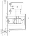
- An embodiment of the invention is shown in the figure in the form of a circuit of short-circuit protection with DVR voltage variation compensator ( fig. 1 ).
- the system for short-circuit protection of the voltage variation compensator DVR is equipped with a control system USZ, the input A1 of which is connected via the discriminator D1 to the current sensor I U2 of the booster transformer TD secondary winding.
- the input A2 of the control system USZ is connected via discriminator D2 to the current sensor I DC capacitor C of the circuit DC of the booster voltage converter P of the compensator DVR.
- the output B1 of the control USZ is connected to the control input S of the semiconductor switch LP.
- the semiconductor switch LP is connected in parallel with the primary winding U1 of the booster transformer TD and with the contacts of the shunt contactor S1.
- the output B2 of the control system USZ is connected to the shunt contactor S1, whose contacts are connected in parallel with the semiconductor switch LP and with the primary winding U1 of the booster transformer TD and with the contacts of the cutoff contactor S2.
- the output B3 of the control system USZ is connected to the cutoff contactor S2, the contacts of which are connected on one side to terminals 3 and 4 of the booster voltage converter P , and on the other side to the two ends of the primary winding U1 of the booster transformer TD and to the semiconductor switch LP connected to it in parallel, as well as to the contacts of the shunt contactor S1.
- the output B4 of the control system USZ is connected to the cutoff contactor S3, the contacts of which are connected on one side to terminals Z1 and Z2 of the 0.4 kV power grid, and on the other side to terminals 1 and 2 of the booster voltage converter P of the DVR voltage variation compensator.
- Operation of the DVR voltage variation compensator short-circuit protection is triggered by a change in the signal at the output of discriminator D1 or D2 or at the outputs of both discriminators D1 and D2 simultaneously.
- the discriminator D1 detects the exceeding of the threshold value of the secondary winding U2 current of the booster transformer TD, measured by the sensor I U2 .
- the discriminator D2 detects the exceeding of the threshold value of the current of the capacitor C of the circuit DC of the booster voltage converter P measured by the sensor I DC .
- discriminators D1, D2 actuate the control system USZ, which immediately produces control signals to switch on the solid-state switch LP and shunt contactor S1, and to open cut-off contactors S2 and S3.
- the solid-state switch LP due to its very short eigentime turns on first and short-circuits the primary winding U1 of the booster transformer TD blocking the build-up of voltage on it.
- the bypass contactor S1 has a longer eigentime due to which it turns on after switch LP switching on by short-circuiting the semiconductor switch LP and winding U1 of the transformer TD.
- the cut-off contactors S2 and S3 open, disconnecting the booster voltage converter P from the shorted winding U1 of the booster transformer TD and from the 0.4 kV power grid.
- Tripping of the short-circuit protection of the faulty load Obc restores normal power supply conditions in the 0.4 kV power grid and automatically puts the DVR voltage variation compensator back into operation in the 0.4 kV power grid.
- the short eigentime of switching on the semiconductor switch LP of the order of microseconds allows the primary winding U1 of the booster transformer TD to be short-circuited very quickly and limits the increase in the peak value of the voltage on this primary winding U1 already at a low level, safe for the transistors of the booster voltage converter P.
- the operation of the short-circuit protection of the DVR voltage variation compensator does not interfere with the current flow in the secondary winding U2 of the booster transformer TD, ensuring stable and continuous power supply to the loads Obc.
- the solid-state switch LP and the shunt contactor S1 remain permanently closed, permanently short-circuiting the primary winding U1 of the booster transformer TD.
- the cut-off contactors S2, S3 also remain permanently open, disconnecting the faulty booster voltage converter P from the 0.4 kV power grid and from the primary winding U1 of the booster transformer TD. Such a state of the contactors S1, S2 and S3, as well as the semiconductor switch LP is maintained until the faulty booster voltage converter P is replaced by the service and the compensator of operating voltage changes in the 0.4 kV power grid is manually switched on.
Landscapes
- Engineering & Computer Science (AREA)
- Power Engineering (AREA)
- Supply And Distribution Of Alternating Current (AREA)
- Protection Of Static Devices (AREA)
Applications Claiming Priority (1)
| Application Number | Priority Date | Filing Date | Title |
|---|---|---|---|
| PL443881A PL443881A1 (pl) | 2023-02-23 | 2023-02-23 | Sposób i układ do zabezpieczenia zwarciowego kompensatora zmian napięcia DVR |
Publications (1)
| Publication Number | Publication Date |
|---|---|
| EP4422010A1 true EP4422010A1 (de) | 2024-08-28 |
Family
ID=87845536
Family Applications (1)
| Application Number | Title | Priority Date | Filing Date |
|---|---|---|---|
| EP23461633.2A Pending EP4422010A1 (de) | 2023-02-23 | 2023-07-28 | Verfahren und schaltungsanordnung zum kurzschlussschutz eines dvr-spannungsschwankungskompensators |
Country Status (2)
| Country | Link |
|---|---|
| EP (1) | EP4422010A1 (de) |
| PL (1) | PL443881A1 (de) |
Family Cites Families (3)
| Publication number | Priority date | Publication date | Assignee | Title |
|---|---|---|---|---|
| US5734256A (en) * | 1995-05-31 | 1998-03-31 | General Electric Company | Apparatus for protection of power-electronics in series compensating systems |
| JP3429932B2 (ja) * | 1995-12-13 | 2003-07-28 | 三菱電機株式会社 | 電力変換器用保護装置 |
| CN107947173B (zh) * | 2017-12-20 | 2024-02-02 | 南京南瑞继保电气有限公司 | 一种串联补偿器及控制方法 |
-
2023
- 2023-02-23 PL PL443881A patent/PL443881A1/pl unknown
- 2023-07-28 EP EP23461633.2A patent/EP4422010A1/de active Pending
Non-Patent Citations (5)
| Title |
|---|
| "Dynamic Voltage Restorer (DVR) System for Compensation of Voltage Sags, State -of-the-Art Review", INTERNATIONAL JOURNAL OF COMPUTATIONAL ENGINEERING RESEARCH, vol. 3, no. 1, May 2014 (2014-05-01), Retrieved from the Internet <URL:ijceronline.com> |
| "Protection of DVR against Short Circuit Faults at the Load Side", 2006 3RD IET INTERNATIONAL CONFERENCE ON POWER ELECTRONICS, MACHINES AND DRIVES - PEMD, 2006 |
| FARHADI-KANGARLU MOHAMMAD ET AL: "A comprehensive review of dynamic voltage restorers", INTERNATIONAL JOURNAL OF ELECTRICAL POWER & ENERGY SYSTEMS, JORDAN HILL, OXFORD, GB, vol. 92, 11 May 2017 (2017-05-11), pages 136 - 155, XP085055077, ISSN: 0142-0615, DOI: 10.1016/J.IJEPES.2017.04.013 * |
| SOWMYASHREE N ET AL: "Review of Dynamic Voltage Restorer (DVR) Based Controlling Approaches for Grid Networks", 2022 IEEE 2ND MYSORE SUB SECTION INTERNATIONAL CONFERENCE (MYSURUCON), IEEE, 16 October 2022 (2022-10-16), pages 1 - 8, XP034246578, DOI: 10.1109/MYSURUCON55714.2022.9972425 * |
| YUN WEI LI ET AL: "A Dual-Functional Medium Voltage Level DVR to Limit Downstream Fault Currents", IEEE TRANSACTIONS ON POWER ELECTRONICS, INSTITUTE OF ELECTRICAL AND ELECTRONICS ENGINEERS, USA, vol. 22, no. 4, 1 July 2007 (2007-07-01), pages 1330 - 1340, XP011186921, ISSN: 0885-8993, DOI: 10.1109/TPEL.2007.900589 * |
Also Published As
| Publication number | Publication date |
|---|---|
| PL443881A1 (pl) | 2024-08-26 |
Similar Documents
| Publication | Publication Date | Title |
|---|---|---|
| Walling et al. | Summary of distributed resources impact on power delivery systems | |
| RU2510092C2 (ru) | Устройство и способ для прерывания тока в линии передачи или распределения энергии и компоновка ограничения тока | |
| US5734256A (en) | Apparatus for protection of power-electronics in series compensating systems | |
| CN113270864A (zh) | 一种配电网合环运行的柔性控制系统 | |
| EP3036813B1 (de) | Schutzschaltung auf ac-seite einer hvdc | |
| US20150092311A1 (en) | Methods, systems, and computer readable media for protection of direct current building electrical systems | |
| KR19980018252A (ko) | 전력 수용 스테이션용 보호 장치 | |
| US20180301980A1 (en) | Power management utilizing a blocker stage | |
| KR102128442B1 (ko) | 메인 변압기의 oltc 보호장치 | |
| KR20150130182A (ko) | 한류기 | |
| EP4422010A1 (de) | Verfahren und schaltungsanordnung zum kurzschlussschutz eines dvr-spannungsschwankungskompensators | |
| CN215452515U (zh) | 一种配电网合环运行的柔性控制系统 | |
| Kunde et al. | Integration of fast acting electronic fault current limiters (EFCL) in medium voltage systems | |
| US12308637B2 (en) | Current sinking arrangement | |
| CN109075559B (zh) | 用于保护连接在多相网络上的用电器的具有低压和过压切断功能的电路布置系统 | |
| Lulbadda et al. | Protection schemes of solid state transformers for different fault conditions | |
| RU2399136C1 (ru) | Способ отключения короткого замыкания в электрической сети переменного тока высокого напряжения | |
| Brewis et al. | Theory and practical performance of interlocked overcurrent busbar zone protection in distribution substations | |
| KR20170042070A (ko) | 전력계통에서의 단락 발생시 재해 방지장치 및 방법 | |
| Rai et al. | Overcurrent Relay Using Voltage Control | |
| KR101948834B1 (ko) | 돌입 전류 차단 기능 및 과부하 차단 기능을 갖는 순간정전 보상 장치 및 순간정전 보상 모듈 | |
| JP4072961B2 (ja) | Sog開閉器の系統連系保護機能を備えた制御装置 | |
| Cuttino | Extending the use of shunt capacitors by means of automatic switching | |
| JP4033136B2 (ja) | 過電流保護システム | |
| KR20240058590A (ko) | 루프 배전 선로의 수지상 운전시 전압 보상 운전 방법 및 장치 |
Legal Events
| Date | Code | Title | Description |
|---|---|---|---|
| PUAI | Public reference made under article 153(3) epc to a published international application that has entered the european phase |
Free format text: ORIGINAL CODE: 0009012 |
|
| STAA | Information on the status of an ep patent application or granted ep patent |
Free format text: STATUS: THE APPLICATION HAS BEEN PUBLISHED |
|
| AK | Designated contracting states |
Kind code of ref document: A1 Designated state(s): AL AT BE BG CH CY CZ DE DK EE ES FI FR GB GR HR HU IE IS IT LI LT LU LV MC ME MK MT NL NO PL PT RO RS SE SI SK SM TR |
|
| STAA | Information on the status of an ep patent application or granted ep patent |
Free format text: STATUS: REQUEST FOR EXAMINATION WAS MADE |
|
| 17P | Request for examination filed |
Effective date: 20241220 |
|
| GRAP | Despatch of communication of intention to grant a patent |
Free format text: ORIGINAL CODE: EPIDOSNIGR1 |
|
| STAA | Information on the status of an ep patent application or granted ep patent |
Free format text: STATUS: GRANT OF PATENT IS INTENDED |
|
| RIC1 | Information provided on ipc code assigned before grant |
Ipc: H02H 7/12 20060101AFI20251101BHEP |
|
| INTG | Intention to grant announced |
Effective date: 20251201 |
|
| GRAS | Grant fee paid |
Free format text: ORIGINAL CODE: EPIDOSNIGR3 |
|
| GRAA | (expected) grant |
Free format text: ORIGINAL CODE: 0009210 |
|
| STAA | Information on the status of an ep patent application or granted ep patent |
Free format text: STATUS: THE PATENT HAS BEEN GRANTED |