EP4421964A1 - Intermodule bus bar capable of delaying thermal runaway transition, and battery pack comprising same - Google Patents
Intermodule bus bar capable of delaying thermal runaway transition, and battery pack comprising same Download PDFInfo
- Publication number
- EP4421964A1 EP4421964A1 EP23883081.4A EP23883081A EP4421964A1 EP 4421964 A1 EP4421964 A1 EP 4421964A1 EP 23883081 A EP23883081 A EP 23883081A EP 4421964 A1 EP4421964 A1 EP 4421964A1
- Authority
- EP
- European Patent Office
- Prior art keywords
- inter
- metal plate
- hole
- module busbar
- busbar according
- Prior art date
- Legal status (The legal status is an assumption and is not a legal conclusion. Google has not performed a legal analysis and makes no representation as to the accuracy of the status listed.)
- Granted
Links
Images




Classifications
-
- H—ELECTRICITY
- H01—ELECTRIC ELEMENTS
- H01M—PROCESSES OR MEANS, e.g. BATTERIES, FOR THE DIRECT CONVERSION OF CHEMICAL ENERGY INTO ELECTRICAL ENERGY
- H01M50/00—Constructional details or processes of manufacture of the non-active parts of electrochemical cells other than fuel cells, e.g. hybrid cells
- H01M50/30—Arrangements for facilitating escape of gases
- H01M50/375—Vent means sensitive to or responsive to temperature
-
- H—ELECTRICITY
- H01—ELECTRIC ELEMENTS
- H01M—PROCESSES OR MEANS, e.g. BATTERIES, FOR THE DIRECT CONVERSION OF CHEMICAL ENERGY INTO ELECTRICAL ENERGY
- H01M50/00—Constructional details or processes of manufacture of the non-active parts of electrochemical cells other than fuel cells, e.g. hybrid cells
- H01M50/50—Current conducting connections for cells or batteries
- H01M50/502—Interconnectors for connecting terminals of adjacent batteries; Interconnectors for connecting cells outside a battery casing
- H01M50/503—Interconnectors for connecting terminals of adjacent batteries; Interconnectors for connecting cells outside a battery casing characterised by the shape of the interconnectors
-
- H—ELECTRICITY
- H01—ELECTRIC ELEMENTS
- H01M—PROCESSES OR MEANS, e.g. BATTERIES, FOR THE DIRECT CONVERSION OF CHEMICAL ENERGY INTO ELECTRICAL ENERGY
- H01M50/00—Constructional details or processes of manufacture of the non-active parts of electrochemical cells other than fuel cells, e.g. hybrid cells
- H01M50/20—Mountings; Secondary casings or frames; Racks, modules or packs; Suspension devices; Shock absorbers; Transport or carrying devices; Holders
- H01M50/204—Racks, modules or packs for multiple batteries or multiple cells
-
- H—ELECTRICITY
- H01—ELECTRIC ELEMENTS
- H01M—PROCESSES OR MEANS, e.g. BATTERIES, FOR THE DIRECT CONVERSION OF CHEMICAL ENERGY INTO ELECTRICAL ENERGY
- H01M50/00—Constructional details or processes of manufacture of the non-active parts of electrochemical cells other than fuel cells, e.g. hybrid cells
- H01M50/20—Mountings; Secondary casings or frames; Racks, modules or packs; Suspension devices; Shock absorbers; Transport or carrying devices; Holders
- H01M50/233—Mountings; Secondary casings or frames; Racks, modules or packs; Suspension devices; Shock absorbers; Transport or carrying devices; Holders characterised by physical properties of casings or racks, e.g. dimensions
- H01M50/24—Mountings; Secondary casings or frames; Racks, modules or packs; Suspension devices; Shock absorbers; Transport or carrying devices; Holders characterised by physical properties of casings or racks, e.g. dimensions adapted for protecting batteries from their environment, e.g. from corrosion
-
- H—ELECTRICITY
- H01—ELECTRIC ELEMENTS
- H01M—PROCESSES OR MEANS, e.g. BATTERIES, FOR THE DIRECT CONVERSION OF CHEMICAL ENERGY INTO ELECTRICAL ENERGY
- H01M50/00—Constructional details or processes of manufacture of the non-active parts of electrochemical cells other than fuel cells, e.g. hybrid cells
- H01M50/50—Current conducting connections for cells or batteries
- H01M50/502—Interconnectors for connecting terminals of adjacent batteries; Interconnectors for connecting cells outside a battery casing
- H01M50/505—Interconnectors for connecting terminals of adjacent batteries; Interconnectors for connecting cells outside a battery casing comprising a single busbar
-
- H—ELECTRICITY
- H01—ELECTRIC ELEMENTS
- H01M—PROCESSES OR MEANS, e.g. BATTERIES, FOR THE DIRECT CONVERSION OF CHEMICAL ENERGY INTO ELECTRICAL ENERGY
- H01M50/00—Constructional details or processes of manufacture of the non-active parts of electrochemical cells other than fuel cells, e.g. hybrid cells
- H01M50/50—Current conducting connections for cells or batteries
- H01M50/502—Interconnectors for connecting terminals of adjacent batteries; Interconnectors for connecting cells outside a battery casing
- H01M50/507—Interconnectors for connecting terminals of adjacent batteries; Interconnectors for connecting cells outside a battery casing comprising an arrangement of two or more busbars within a container structure, e.g. busbar modules
-
- H—ELECTRICITY
- H01—ELECTRIC ELEMENTS
- H01M—PROCESSES OR MEANS, e.g. BATTERIES, FOR THE DIRECT CONVERSION OF CHEMICAL ENERGY INTO ELECTRICAL ENERGY
- H01M50/00—Constructional details or processes of manufacture of the non-active parts of electrochemical cells other than fuel cells, e.g. hybrid cells
- H01M50/50—Current conducting connections for cells or batteries
- H01M50/502—Interconnectors for connecting terminals of adjacent batteries; Interconnectors for connecting cells outside a battery casing
- H01M50/521—Interconnectors for connecting terminals of adjacent batteries; Interconnectors for connecting cells outside a battery casing characterised by the material
- H01M50/522—Inorganic material
-
- H—ELECTRICITY
- H01—ELECTRIC ELEMENTS
- H01M—PROCESSES OR MEANS, e.g. BATTERIES, FOR THE DIRECT CONVERSION OF CHEMICAL ENERGY INTO ELECTRICAL ENERGY
- H01M50/00—Constructional details or processes of manufacture of the non-active parts of electrochemical cells other than fuel cells, e.g. hybrid cells
- H01M50/50—Current conducting connections for cells or batteries
- H01M50/502—Interconnectors for connecting terminals of adjacent batteries; Interconnectors for connecting cells outside a battery casing
- H01M50/521—Interconnectors for connecting terminals of adjacent batteries; Interconnectors for connecting cells outside a battery casing characterised by the material
- H01M50/524—Organic material
-
- H—ELECTRICITY
- H01—ELECTRIC ELEMENTS
- H01M—PROCESSES OR MEANS, e.g. BATTERIES, FOR THE DIRECT CONVERSION OF CHEMICAL ENERGY INTO ELECTRICAL ENERGY
- H01M50/00—Constructional details or processes of manufacture of the non-active parts of electrochemical cells other than fuel cells, e.g. hybrid cells
- H01M50/50—Current conducting connections for cells or batteries
- H01M50/502—Interconnectors for connecting terminals of adjacent batteries; Interconnectors for connecting cells outside a battery casing
- H01M50/521—Interconnectors for connecting terminals of adjacent batteries; Interconnectors for connecting cells outside a battery casing characterised by the material
- H01M50/526—Interconnectors for connecting terminals of adjacent batteries; Interconnectors for connecting cells outside a battery casing characterised by the material having a layered structure
-
- H—ELECTRICITY
- H01—ELECTRIC ELEMENTS
- H01M—PROCESSES OR MEANS, e.g. BATTERIES, FOR THE DIRECT CONVERSION OF CHEMICAL ENERGY INTO ELECTRICAL ENERGY
- H01M10/00—Secondary cells; Manufacture thereof
- H01M10/60—Heating or cooling; Temperature control
- H01M10/65—Means for temperature control structurally associated with the cells
- H01M10/658—Means for temperature control structurally associated with the cells by thermal insulation or shielding
-
- H—ELECTRICITY
- H01—ELECTRIC ELEMENTS
- H01M—PROCESSES OR MEANS, e.g. BATTERIES, FOR THE DIRECT CONVERSION OF CHEMICAL ENERGY INTO ELECTRICAL ENERGY
- H01M2220/00—Batteries for particular applications
- H01M2220/20—Batteries in motive systems, e.g. vehicle, ship, plane
-
- H—ELECTRICITY
- H01—ELECTRIC ELEMENTS
- H01M—PROCESSES OR MEANS, e.g. BATTERIES, FOR THE DIRECT CONVERSION OF CHEMICAL ENERGY INTO ELECTRICAL ENERGY
- H01M50/00—Constructional details or processes of manufacture of the non-active parts of electrochemical cells other than fuel cells, e.g. hybrid cells
- H01M50/30—Arrangements for facilitating escape of gases
- H01M50/35—Gas exhaust passages comprising elongated, tortuous or labyrinth-shaped exhaust passages
- H01M50/358—External gas exhaust passages located on the battery cover or case
-
- H—ELECTRICITY
- H01—ELECTRIC ELEMENTS
- H01R—ELECTRICALLY-CONDUCTIVE CONNECTIONS; STRUCTURAL ASSOCIATIONS OF A PLURALITY OF MUTUALLY-INSULATED ELECTRICAL CONNECTING ELEMENTS; COUPLING DEVICES; CURRENT COLLECTORS
- H01R25/00—Coupling parts adapted for simultaneous co-operation with two or more identical counterparts, e.g. for distributing energy to two or more circuits
- H01R25/16—Rails or bus-bars provided with a plurality of discrete connecting locations for counterparts
- H01R25/161—Details
- H01R25/162—Electrical connections between or with rails or bus-bars
-
- H—ELECTRICITY
- H02—GENERATION; CONVERSION OR DISTRIBUTION OF ELECTRIC POWER
- H02G—INSTALLATION OF ELECTRIC CABLES OR LINES, OR OF COMBINED OPTICAL AND ELECTRIC CABLES OR LINES
- H02G5/00—Installations of bus-bars
- H02G5/005—Laminated bus-bars
-
- Y—GENERAL TAGGING OF NEW TECHNOLOGICAL DEVELOPMENTS; GENERAL TAGGING OF CROSS-SECTIONAL TECHNOLOGIES SPANNING OVER SEVERAL SECTIONS OF THE IPC; TECHNICAL SUBJECTS COVERED BY FORMER USPC CROSS-REFERENCE ART COLLECTIONS [XRACs] AND DIGESTS
- Y02—TECHNOLOGIES OR APPLICATIONS FOR MITIGATION OR ADAPTATION AGAINST CLIMATE CHANGE
- Y02E—REDUCTION OF GREENHOUSE GAS [GHG] EMISSIONS, RELATED TO ENERGY GENERATION, TRANSMISSION OR DISTRIBUTION
- Y02E60/00—Enabling technologies; Technologies with a potential or indirect contribution to GHG emissions mitigation
- Y02E60/10—Energy storage using batteries
Definitions
- the present invention relates to an inter-module busbar capable of delaying thermal runaway propagation and a battery pack including the same, and more particularly to an inter-module busbar capable of delaying thermal runaway propagation configured to inhibit explosion caused by high pressure and high temperature due to propagation of fire and venting gas from a battery cell received in a battery pack due to thermal runaway and a battery pack including the same.
- Secondary batteries which are capable of being charged and discharged, are intimately used in daily life.
- secondary batteries are used in mobile devices, electric vehicles, and hybrid electric vehicles.
- fire and venting gas may occur in a battery cell received in a battery module due to external impact, short circuit, overcurrent, etc., and such fire and venting gas may occur instantaneously, whereby damage such as explosion due to high temperature and high pressure may occur.
- FIG. 1 is a perspective view showing a conventional flexible busbar assembly.
- the conventional flexible busbar assembly includes a busbar 10 configured to electrically connect adjacent battery modules to each other and a cover member 20 configured to wrap the busbar 10.
- a specific part of the conventional flexible busbar assembly may be deformed, such as by bending, into a desired shape to easily electrically connect battery modules located on a complex path to each other.
- cover member 20 may melt due to high temperature, and fire and venting gas may move to all neighboring battery modules through a gap formed by melting, resulting in thermal runaway propagation, which may cause further damage.
- Patent Document 1 Korean Patent Application Publication No. 2015-0101154
- the present invention has been made in view of the above problems, and it is an object of the present invention to provide an inter-module busbar capable of delaying thermal runaway propagation configured to guide the movement of venting gas generated by fire in a battery cell to a nearby space, thereby delaying and inhibiting explosion due to high pressure, and a battery pack including the same.
- an inter-module busbar includes a metal plate (100) for electrical connection and a cover member (200) configured to partially encompass the metal plate (100), wherein the metal plate (100) has at least one first through-hole (110) formed therein in a longitudinal direction, and a first closure member (300) is configured to be inserted into the first through-hole (110) of the metal plate (100).
- the first closure member (300) may include a thermoplastic material.
- thermoplastic material may include at least one selected from the group consisting of silicone, polyethylene, polypropylene, polystyrene, and polyvinyl chloride.
- the cover member (200) may include a second through-hole (210), the metal plate (100) configured to be inserted into the second through-hole (210) in the longitudinal direction, and at least one third through-hole (220) spaced apart from the second through-hole (210), and a second closure member (400) being configured to be inserted into the third through-hole (220).
- the second closure member (400) may include a thermoplastic material.
- thermoplastic material may include at least one selected from the group consisting of silicone, polyethylene, polypropylene, polystyrene, and polyvinyl chloride.
- the metal plate (100) may include an upper metal plate (120) and a lower metal plate (130) cut in a horizontal direction.
- the length of the first closure member (300) may be less than half the length of the first through-hole (110).
- the first closure member (300) may be configured to be inserted into the first through-hole (110) in two or more.
- the cover member (200) may include at least one selected from the group consisting of highly heat-resistant silicone, polyphenylene sulfide, polyetheretherketone, polyphthalamide, polyamide, polysulfone, polyethersulfone, polyetherimide, acrylic fiber, and polybenzimidazole.
- the present invention provides a battery pack including the inter-module busbar having the aforementioned features.
- an inter-module busbar according to the present invention has an advantage in that, when fire and venting gas occur in a battery cell, a closure member melts and a through-hole is opened to guide the movement of the venting gas, whereby it is possible to inhibit explosion caused by thermal runaway propagation and high pressure.
- the inter-module busbar according to the present invention has an advantage in that a cover member does not melt at high temperatures, whereby it is possible to inhibit thermal runaway from spreading throughout the interior of a battery pack due to fire and venting gas leakage.
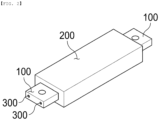
- FIG. 2 is a perspective view showing an inter-module busbar according to a first preferred embodiment of the present invention
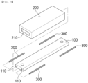
- FIG. 3 is an exploded perspective view showing the inter-module busbar according to the first preferred embodiment of the present invention
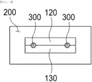
- FIG. 4 is a plan view of the inter-module busbar shown in FIG. 2 when viewed from the front.
- the inter-module busbar may include a metal plate 100, a cover member 200, and a first closure member 300.
- Opposite ends of the metal plate 100 may be exposed to the outside of the cover member 200, and the exposed ends may serve to electrically connect battery modules disposed in a battery pack to each other.
- the metal plate 100 may be bent at a specific part to have different shapes as needed in consideration of the positions of connectors of the battery modules.
- the metal plate 100 may have at least one first through-hole 110 spaced apart from an edge of the metal plate 100 and formed therethrough in a longitudinal direction.
- the first through-hole 110 may guide the movement of venting gas caused by fire and thermal runaway in a battery cell, whereby it is possible to prevent explosion of the battery cell due to high pressure caused by instantaneous generation of a large amount of venting gas.
- a battery pack may have a plurality of receiving spaces defined by a partition wall, a battery module may be received in each receiving space, and adjacent ones of the battery modules received in the receiving spaces may be electrically connected to each other via an inter-module busbar extending through the partition wall.
- venting gas is generated in a battery cell received in a specific one of the plurality of battery modules due to overcurrent and thermal runaway, whereby the pressure in the space in which the battery module is received may increase.
- the venting gas may move to an adjacent receiving space along the first through-hole 110, whereby pressure rise in the receiving space in which the venting gas has been generated may be relieved, and therefore it is possible to prevent explosion due to high pressure.
- the cover member 200 is configured to partially encompass the metal plate 100 excluding opposite ends in order to maintain an insulated state of the encompassed part of the metal plate 100, and may be made of an insulative material.
- the cover member 200 may be made of a material that does not melt at high temperatures, such as fire and venting gas resulting from thermal runaway.
- the cover member 200 may include at least one selected from the group consisting of highly heat-resistant silicone, polyphenylene sulfide, polyetheretherketone, polyphthalamide, polyamide, polysulfone, polyethersulfone, polyetherimide, acrylic fiber, and polybenzimidazole.
- the highly heat-resistant silicone exhibits the same performance as commonly used silicone at room temperature, but at high temperatures, the structure of the highly heat-resistant silicone is changed to a ceramized structure, whereby the highly heat-resistant silicone has ceramic properties, and therefore the highly heat-resistant silicone may exhibit impact resistance while maintaining certain strength.
- the cover member 200 may be maintained in shape without being damaged or broken, whereby it is possible to maintain an insulated state of the metal plate 100, and therefore it is possible to prevent the occurrence of short circuit due to contact between a nearby metal material and the metal plate 100.
- the cover member 200 may have a second through-hole 210 formed through a central part thereof in a longitudinal direction, and the metal plate 100 may be inserted into and located in the second through-hole 210.
- the metal plate 100 may be located such that opposite ends thereof are exposed out of the cover member 200.
- the first closure member 300 may be formed in the shape of an elongated rod, may be inserted into, and located in the first through-hole 110 of the metal plate 100, and may be made of a thermoplastic material.
- the first closure member 300 may be formed in the same shape as the first through-hole 110.
- thermoplastic material of which the first closure member 300 is made, may include at least one selected from the group consisting of silicone, polyethylene, polypropylene, polystyrene, and polyvinyl chloride.
- the first closure member 300 blocks the first through-hole 110 to prevent the movement of air to a space in which a neighboring battery module is located through the first through-hole 110, and when the first closure member melts due to high-temperature fire and venting gas, the venting gas moves through the first through-hole 110.
- the first closure member 300 is maintained in shape when conditions, such as high temperature and high pressure, are not satisfied, and therefore it is possible to inhibit the movement more than necessary of fire and venting gas into a space in which a neighboring battery module is located.
- FIG. 5 is an exploded perspective view showing an inter-module busbar according to a second preferred embodiment of the present invention
- FIG. 6 is a plan view of the inter-module busbar shown in FIG. 5 when viewed from the front.
- the inter-module busbar according to the second preferred embodiment of the present invention is identical to the inter-module busbar according to the first embodiment described with reference to FIGs. 2 to 4 except for the shape of a cover member 200 and further provision of a second closure member 400, and therefore a description of the same configuration will be omitted.
- the cover member 200 may have a third through-hole 220 spaced apart from a second through-hole 210, through which a metal plate 100 is inserted, by a predetermined distance, the third through-hole being formed through the cover member 200 in the longitudinal direction.
- the third through-hole 220 may guide the movement of the venting gas, whereby it is possible to relieve pressure caused by the venting gas.
- a second closure member 400 formed in the shape of an elongated rod may be inserted into and located in the third through-hole 220.
- the second closure member 400 may be made of a thermoplastic material, and as an example, the thermoplastic material may include at least one selected from the group consisting of silicone, polyethylene, polypropylene, polystyrene, and polyvinyl chloride.
- the second closure member 400 blocks the third through-hole 220 to prevent the movement of air to a space in which a neighboring battery module is located through the third through-hole 220, and when the second closure member melts due to high-temperature fire and venting gas, the venting gas moves through the first through-hole 110.
- venting gas may move due to destruction by fire of the second closure member 400, whereby pressure rise due to the venting gas may be relieved, and therefore it is possible to inhibit explosion due to high pressure.
- FIG. 7 is an exploded perspective view showing an inter-module busbar according to a third preferred embodiment of the present invention
- FIG. 8 is a plan view of the inter-module busbar shown in FIG. 7 when viewed from the front.
- the inter-module busbar according to the third preferred embodiment of the present invention is identical to the inter-module busbar according to the first embodiment described with reference to FIGs. 2 to 4 except for the shape of a metal plate 100, and therefore a description of the same configuration will be omitted.
- the metal plate 100 according to the third embodiment of the present invention may include an upper metal plate 120 and a lower metal plate 130 cut in a horizontal direction.
- the metal plate 100 is constituted by the upper metal plate 120 and the lower metal plate 130, it is possible to easily locate a first closure member 300 in a first through-hole 110 of the metal plate 100, whereby manufacturing efficiency is improved.
- FIG. 9 is an exploded perspective view showing an inter-module busbar according to a fourth preferred embodiment of the present invention
- FIG. 10 is a plan view of the inter-module busbar shown in FIG. 9 when viewed from the front.
- the inter-module busbar according to the fourth preferred embodiment of the present invention is identical to the inter-module busbar according to the first embodiment described with reference to FIGs. 2 to 4 except for the shape of a first closure member 300, and therefore a description of the same configuration will be omitted.
- the length of the first closure member 300 according to the fourth embodiment of the present invention may be formed so as to be less than half the length of a first through-hole 110.
- Two or more first closure members 300 may be inserted into one first through-hole 110.
- a part of the first through-hole 110 may not be filled with the first closure member 300, whereby it is possible to reduce manufacturing costs, and the first closure member 300 may be pushed by high pressure and may be discharged from the first through-hole 110 to guide the movement of venting gas, whereby it is possible to further improve pressure regulation performance against high pressure.
- the second closure member 400 according to the second embodiment shown in FIGs. 6 and 7 may be formed so as to be less than half the length of the third through-hole 220, like the first closure member 300, whereby a plurality of second closure members 400 may be inserted into and located in a single third through-hole 220.
- the present invention may provide a battery pack including the inter-module busbar and a device having the battery pack mounted therein.
Landscapes
- Chemical & Material Sciences (AREA)
- Chemical Kinetics & Catalysis (AREA)
- Electrochemistry (AREA)
- General Chemical & Material Sciences (AREA)
- Inorganic Chemistry (AREA)
- Battery Mounting, Suspending (AREA)
- Connection Of Batteries Or Terminals (AREA)
- Gas Exhaust Devices For Batteries (AREA)
Abstract
Description
- This application claims the benefit of priority to
Korean Patent Application No. 2022-0139104 filed on October 26, 2022 - The present invention relates to an inter-module busbar capable of delaying thermal runaway propagation and a battery pack including the same, and more particularly to an inter-module busbar capable of delaying thermal runaway propagation configured to inhibit explosion caused by high pressure and high temperature due to propagation of fire and venting gas from a battery cell received in a battery pack due to thermal runaway and a battery pack including the same.
- With recent development of alternative energies due to air pollution and energy depletion caused as the result of use of fossil fuels, demand for secondary batteries capable of storing electrical energy that is produced has increased. Secondary batteries, which are capable of being charged and discharged, are intimately used in daily life. For example, secondary batteries are used in mobile devices, electric vehicles, and hybrid electric vehicles.
- Required capacities of secondary batteries used as energy sources of various kinds of electronic devices inevitably used in modern society have been increased due to an increase in usage of mobile devices, increasing complexity of the mobile devices, and development of electric vehicles. In order to satisfy demand of users, a plurality of battery cells is disposed in a small-sized device, whereas a battery module including a plurality of battery cells electrically connected to each other or a battery pack including a plurality of battery modules is used in a vehicle, etc.
- Meanwhile, fire and venting gas may occur in a battery cell received in a battery module due to external impact, short circuit, overcurrent, etc., and such fire and venting gas may occur instantaneously, whereby damage such as explosion due to high temperature and high pressure may occur.
-
FIG. 1 is a perspective view showing a conventional flexible busbar assembly. As shown inFIG. 1 , the conventional flexible busbar assembly includes abusbar 10 configured to electrically connect adjacent battery modules to each other and acover member 20 configured to wrap thebusbar 10. - A specific part of the conventional flexible busbar assembly may be deformed, such as by bending, into a desired shape to easily electrically connect battery modules located on a complex path to each other.
- When fire and venting gas occur in a battery cell in a battery module due to thermal runaway, however, no means configured to relieve pressure rise due to the venting gas is provided, whereby explosion due to high pressure may occur.
- In addition, the
cover member 20 may melt due to high temperature, and fire and venting gas may move to all neighboring battery modules through a gap formed by melting, resulting in thermal runaway propagation, which may cause further damage. - (Patent Document 1)
Korean Patent Application Publication No. 2015-0101154 - The present invention has been made in view of the above problems, and it is an object of the present invention to provide an inter-module busbar capable of delaying thermal runaway propagation configured to guide the movement of venting gas generated by fire in a battery cell to a nearby space, thereby delaying and inhibiting explosion due to high pressure, and a battery pack including the same.
- It is another object of the present invention to provide an inter-module busbar capable of delaying thermal runaway propagation configured such that a cover member does not melt at high temperatures, thereby inhibiting propagation of fire and thermal runaway to the entire interior of a battery pack as the result of the cover member melting at high temperatures due to thermal runaway, and a battery pack including the same.
- In order to accomplish the above objects, an inter-module busbar according to the present invention includes a metal plate (100) for electrical connection and a cover member (200) configured to partially encompass the metal plate (100), wherein the metal plate (100) has at least one first through-hole (110) formed therein in a longitudinal direction, and a first closure member (300) is configured to be inserted into the first through-hole (110) of the metal plate (100).
- Also, in the inter-module busbar according to the present invention, the first closure member (300) may include a thermoplastic material.
- Also, in the inter-module busbar according to the present invention, the thermoplastic material may include at least one selected from the group consisting of silicone, polyethylene, polypropylene, polystyrene, and polyvinyl chloride.
- Also, in the inter-module busbar according to the present invention, the cover member (200) may include a second through-hole (210), the metal plate (100) configured to be inserted into the second through-hole (210) in the longitudinal direction, and at least one third through-hole (220) spaced apart from the second through-hole (210), and a second closure member (400) being configured to be inserted into the third through-hole (220).
- Also, in the inter-module busbar according to the present invention, the second closure member (400) may include a thermoplastic material.
- Also, in the inter-module busbar according to the present invention, the thermoplastic material may include at least one selected from the group consisting of silicone, polyethylene, polypropylene, polystyrene, and polyvinyl chloride.
- Also, in the inter-module busbar according to the present invention, the metal plate (100) may include an upper metal plate (120) and a lower metal plate (130) cut in a horizontal direction.
- Also, in the inter-module busbar according to the present invention, the length of the first closure member (300) may be less than half the length of the first through-hole (110).
- Also, in the inter-module busbar according to the present invention, the first closure member (300) may be configured to be inserted into the first through-hole (110) in two or more.
- Also, in the inter-module busbar according to the present invention, the cover member (200) may include at least one selected from the group consisting of highly heat-resistant silicone, polyphenylene sulfide, polyetheretherketone, polyphthalamide, polyamide, polysulfone, polyethersulfone, polyetherimide, acrylic fiber, and polybenzimidazole.
- In addition, the present invention provides a battery pack including the inter-module busbar having the aforementioned features.
- As is apparent from the above description, an inter-module busbar according to the present invention has an advantage in that, when fire and venting gas occur in a battery cell, a closure member melts and a through-hole is opened to guide the movement of the venting gas, whereby it is possible to inhibit explosion caused by thermal runaway propagation and high pressure.
- In addition, the inter-module busbar according to the present invention has an advantage in that a cover member does not melt at high temperatures, whereby it is possible to inhibit thermal runaway from spreading throughout the interior of a battery pack due to fire and venting gas leakage.
-
-
FIG. 1 is a perspective view showing a conventional flexible busbar assembly. -
FIG. 2 is a perspective view showing an inter-module busbar according to a first preferred embodiment of the present invention. -
FIG. 3 is an exploded perspective view showing the inter-module busbar according to the first preferred embodiment of the present invention. -
FIG. 4 is a plan view of the inter-module busbar shown inFIG. 2 when viewed from the front. -
FIG. 5 is an exploded perspective view showing an inter-module busbar according to a second preferred embodiment of the present invention. -
FIG. 6 is a plan view of the inter-module busbar shown inFIG. 5 when viewed from the front. -
FIG. 7 is an exploded perspective view showing an inter-module busbar according to a third preferred embodiment of the present invention. -
FIG. 8 is a plan view of the inter-module busbar shown inFIG. 7 when viewed from the front. -
FIG. 9 is an exploded perspective view showing an inter-module busbar according to a fourth preferred embodiment of the present invention. -
FIG. 10 is a plan view of the inter-module busbar shown inFIG. 9 when viewed from the front. - Now, preferred embodiments of the present invention will be described in detail with reference to the accompanying drawings such that the preferred embodiments of the present invention can be easily implemented by a person having ordinary skill in the art to which the present invention pertains. In describing the principle of operation of the preferred embodiments of the present invention in detail, however, a detailed description of known functions and configurations incorporated herein will be omitted when the same may obscure the subject matter of the present invention.
- In addition, the same reference numbers will be used throughout the drawings to refer to parts that perform similar functions or operations. In the case in which one part is the to be connected to another part in the entire specification, not only may the one part be directly connected to the other part, but also, the one part may be indirectly connected to the other part via a further part. In addition, that a certain element is included does not mean that other elements are excluded, but means that such elements may be further included unless mentioned otherwise.
- Hereinafter, an inter-module busbar capable of delaying thermal runaway propagation according to the present invention and a battery pack including the same will be described with reference to the accompanying drawings.
-
FIG. 2 is a perspective view showing an inter-module busbar according to a first preferred embodiment of the present invention,FIG. 3 is an exploded perspective view showing the inter-module busbar according to the first preferred embodiment of the present invention, andFIG. 4 is a plan view of the inter-module busbar shown inFIG. 2 when viewed from the front. - As shown in
FIGs. 2 to 4 , the inter-module busbar according to the present invention may include ametal plate 100, acover member 200, and afirst closure member 300. - Opposite ends of the
metal plate 100 may be exposed to the outside of thecover member 200, and the exposed ends may serve to electrically connect battery modules disposed in a battery pack to each other. - Consequently, it is possible to set the length of the
metal plate 100 in consideration of the distance between the battery modules to be connected and to set the width and thickness of the metal plate in consideration of the amount of current that passes through the metal plate and the resistance of the metal plate. - In addition, the
metal plate 100 may be bent at a specific part to have different shapes as needed in consideration of the positions of connectors of the battery modules. - The
metal plate 100 may have at least one first through-hole 110 spaced apart from an edge of themetal plate 100 and formed therethrough in a longitudinal direction. - The first through-
hole 110 may guide the movement of venting gas caused by fire and thermal runaway in a battery cell, whereby it is possible to prevent explosion of the battery cell due to high pressure caused by instantaneous generation of a large amount of venting gas. - More specifically, as an example, a battery pack may have a plurality of receiving spaces defined by a partition wall, a battery module may be received in each receiving space, and adjacent ones of the battery modules received in the receiving spaces may be electrically connected to each other via an inter-module busbar extending through the partition wall.
- At this time, venting gas is generated in a battery cell received in a specific one of the plurality of battery modules due to overcurrent and thermal runaway, whereby the pressure in the space in which the battery module is received may increase.
- When the
first closure member 300 disposed in the first through-hole 110 by insertion melts due to high temperature caused by the venting gas or is separated from the first through-hole due to pressure caused by the venting gas, whereby the first through-hole 110 is opened, the venting gas may move to an adjacent receiving space along the first through-hole 110, whereby pressure rise in the receiving space in which the venting gas has been generated may be relieved, and therefore it is possible to prevent explosion due to high pressure. - The
cover member 200 is configured to partially encompass themetal plate 100 excluding opposite ends in order to maintain an insulated state of the encompassed part of themetal plate 100, and may be made of an insulative material. - In addition, the
cover member 200 may be made of a material that does not melt at high temperatures, such as fire and venting gas resulting from thermal runaway. As an example, thecover member 200 may include at least one selected from the group consisting of highly heat-resistant silicone, polyphenylene sulfide, polyetheretherketone, polyphthalamide, polyamide, polysulfone, polyethersulfone, polyetherimide, acrylic fiber, and polybenzimidazole. - Here, the highly heat-resistant silicone exhibits the same performance as commonly used silicone at room temperature, but at high temperatures, the structure of the highly heat-resistant silicone is changed to a ceramized structure, whereby the highly heat-resistant silicone has ceramic properties, and therefore the highly heat-resistant silicone may exhibit impact resistance while maintaining certain strength.
- At high temperatures, therefore, the
cover member 200 may be maintained in shape without being damaged or broken, whereby it is possible to maintain an insulated state of themetal plate 100, and therefore it is possible to prevent the occurrence of short circuit due to contact between a nearby metal material and themetal plate 100. - The
cover member 200 may have a second through-hole 210 formed through a central part thereof in a longitudinal direction, and themetal plate 100 may be inserted into and located in the second through-hole 210. - At this time, the
metal plate 100 may be located such that opposite ends thereof are exposed out of thecover member 200. - The
first closure member 300 may be formed in the shape of an elongated rod, may be inserted into, and located in the first through-hole 110 of themetal plate 100, and may be made of a thermoplastic material. - The
first closure member 300 may be formed in the same shape as the first through-hole 110. - As an example, the thermoplastic material, of which the
first closure member 300 is made, may include at least one selected from the group consisting of silicone, polyethylene, polypropylene, polystyrene, and polyvinyl chloride. - In a normal state, therefore, the
first closure member 300 blocks the first through-hole 110 to prevent the movement of air to a space in which a neighboring battery module is located through the first through-hole 110, and when the first closure member melts due to high-temperature fire and venting gas, the venting gas moves through the first through-hole 110. - At this time, the
first closure member 300 is maintained in shape when conditions, such as high temperature and high pressure, are not satisfied, and therefore it is possible to inhibit the movement more than necessary of fire and venting gas into a space in which a neighboring battery module is located. -
FIG. 5 is an exploded perspective view showing an inter-module busbar according to a second preferred embodiment of the present invention, andFIG. 6 is a plan view of the inter-module busbar shown inFIG. 5 when viewed from the front. - Referring to
FIGs. 5 and6 , the inter-module busbar according to the second preferred embodiment of the present invention is identical to the inter-module busbar according to the first embodiment described with reference toFIGs. 2 to 4 except for the shape of acover member 200 and further provision of asecond closure member 400, and therefore a description of the same configuration will be omitted. - In the inter-module busbar according to the second embodiment of the present invention, the
cover member 200 may have a third through-hole 220 spaced apart from a second through-hole 210, through which ametal plate 100 is inserted, by a predetermined distance, the third through-hole being formed through thecover member 200 in the longitudinal direction. - When venting gas is generated in a battery cell due to thermal runaway, the third through-
hole 220 may guide the movement of the venting gas, whereby it is possible to relieve pressure caused by the venting gas. - A
second closure member 400 formed in the shape of an elongated rod may be inserted into and located in the third through-hole 220. - The
second closure member 400 may be made of a thermoplastic material, and as an example, the thermoplastic material may include at least one selected from the group consisting of silicone, polyethylene, polypropylene, polystyrene, and polyvinyl chloride. - In a normal state, therefore, the
second closure member 400 blocks the third through-hole 220 to prevent the movement of air to a space in which a neighboring battery module is located through the third through-hole 220, and when the second closure member melts due to high-temperature fire and venting gas, the venting gas moves through the first through-hole 110. - That is, the venting gas may move due to destruction by fire of the
second closure member 400, whereby pressure rise due to the venting gas may be relieved, and therefore it is possible to inhibit explosion due to high pressure. -
FIG. 7 is an exploded perspective view showing an inter-module busbar according to a third preferred embodiment of the present invention, andFIG. 8 is a plan view of the inter-module busbar shown inFIG. 7 when viewed from the front. - Referring to
FIGs. 7 and8 , the inter-module busbar according to the third preferred embodiment of the present invention is identical to the inter-module busbar according to the first embodiment described with reference toFIGs. 2 to 4 except for the shape of ametal plate 100, and therefore a description of the same configuration will be omitted. - The
metal plate 100 according to the third embodiment of the present invention may include anupper metal plate 120 and alower metal plate 130 cut in a horizontal direction. - Since the
metal plate 100 is constituted by theupper metal plate 120 and thelower metal plate 130, it is possible to easily locate afirst closure member 300 in a first through-hole 110 of themetal plate 100, whereby manufacturing efficiency is improved. -
FIG. 9 is an exploded perspective view showing an inter-module busbar according to a fourth preferred embodiment of the present invention, andFIG. 10 is a plan view of the inter-module busbar shown inFIG. 9 when viewed from the front. - Referring to
FIGs. 9 and10 , the inter-module busbar according to the fourth preferred embodiment of the present invention is identical to the inter-module busbar according to the first embodiment described with reference toFIGs. 2 to 4 except for the shape of afirst closure member 300, and therefore a description of the same configuration will be omitted. - The length of the
first closure member 300 according to the fourth embodiment of the present invention may be formed so as to be less than half the length of a first through-hole 110. - Two or more
first closure members 300 may be inserted into one first through-hole 110. - A part of the first through-
hole 110 may not be filled with thefirst closure member 300, whereby it is possible to reduce manufacturing costs, and thefirst closure member 300 may be pushed by high pressure and may be discharged from the first through-hole 110 to guide the movement of venting gas, whereby it is possible to further improve pressure regulation performance against high pressure. - In addition, the
second closure member 400 according to the second embodiment shown inFIGs. 6 and7 may be formed so as to be less than half the length of the third through-hole 220, like thefirst closure member 300, whereby a plurality ofsecond closure members 400 may be inserted into and located in a single third through-hole 220. - In addition, the present invention may provide a battery pack including the inter-module busbar and a device having the battery pack mounted therein.
- Those skilled in the art to which the present invention pertains will appreciate that various applications and modifications are possible within the category of the present invention based on the above description.
-
- 100: Metal plate
- 110: First through-hole
- 120: Upper metal plate
- 130: Lower metal plate
- 200: Cover member
- 210: Second through-hole
- 220: Third through-hole
- 300: First closure member
- 400: Second closure member
Claims (11)
- An inter-module busbar comprising:a metal plate for electrical connection; anda cover member configured to partially encompass the metal plate,wherein the metal plate has at least one first through-hole formed therein in a longitudinal direction, andwherein a first closure member is configured to be inserted into the first through-hole of the metal plate.
- The inter-module busbar according to claim 1, wherein the first closure member includes a thermoplastic material.
- The inter-module busbar according to claim 2, wherein the thermoplastic material comprises at least one selected from a group consisting of silicone, polyethylene, polypropylene, polystyrene, and polyvinyl chloride.
- The inter-module busbar according to claim 1, wherein the cover member includes a second through-hole, the metal plate configured to be inserted into the second through-hole in the longitudinal direction, and at least one third through-hole spaced apart from the second through-hole, and a second closure member (400) being configured to be inserted into the third through-hole.
- The inter-module busbar according to claim 4, wherein the second closure member includes a thermoplastic material.
- The inter-module busbar according to claim 5, wherein the thermoplastic material comprises at least one selected from a group consisting of silicone, polyethylene, polypropylene, polystyrene, and polyvinyl chloride.
- The inter-module busbar according to claim 1, wherein the metal plate includes an upper metal plate and a lower metal plate cut in a horizontal direction.
- The inter-module busbar according to claim 1, wherein a length of the first closure member is less than half a length of the first through-hole.
- The inter-module busbar according to claim 8, wherein the first closure member is configured to be inserted into the first through-hole in two or more.
- The inter-module busbar according to claim 1, wherein the cover member comprises at least one selected from a group consisting of highly heat-resistant silicone, polyphenylene sulfide, polyetheretherketone, polyphthalamide, polyamide, polysulfone, polyethersulfone, polyetherimide, acrylic fiber, and polybenzimidazole.
- A battery pack comprising the inter-module busbar according to any one of claims 1 to 10.
Applications Claiming Priority (2)
| Application Number | Priority Date | Filing Date | Title |
|---|---|---|---|
| KR1020220139104A KR102953335B1 (en) | 2022-10-26 | 2022-10-26 | Inter-module busbar capable of delaying thermal runaway transition and battery pack including the same |
| PCT/KR2023/016612 WO2024090976A1 (en) | 2022-10-26 | 2023-10-25 | Intermodule bus bar capable of delaying thermal runaway transition, and battery pack comprising same |
Publications (3)
| Publication Number | Publication Date |
|---|---|
| EP4421964A1 true EP4421964A1 (en) | 2024-08-28 |
| EP4421964A4 EP4421964A4 (en) | 2025-01-08 |
| EP4421964B1 EP4421964B1 (en) | 2026-03-18 |
Family
ID=90831325
Family Applications (1)
| Application Number | Title | Priority Date | Filing Date |
|---|---|---|---|
| EP23883081.4A Active EP4421964B1 (en) | 2022-10-26 | 2023-10-25 | Intermodule bus bar capable of delaying thermal runaway transition, and battery pack comprising same |
Country Status (6)
| Country | Link |
|---|---|
| US (1) | US20250062498A1 (en) |
| EP (1) | EP4421964B1 (en) |
| JP (1) | JP7768634B2 (en) |
| KR (1) | KR102953335B1 (en) |
| CN (1) | CN118266125A (en) |
| WO (1) | WO2024090976A1 (en) |
Family Cites Families (14)
| Publication number | Priority date | Publication date | Assignee | Title |
|---|---|---|---|---|
| JP2009176917A (en) * | 2008-01-24 | 2009-08-06 | Fdk Corp | Nonaqueous electrolyte storage device |
| JP2011029103A (en) * | 2009-07-29 | 2011-02-10 | Kawasaki Shipbuilding Corp | Battery cooling device |
| KR101141379B1 (en) * | 2010-07-06 | 2012-05-03 | 삼성전기주식회사 | Energy storage module |
| KR20150101154A (en) | 2014-02-26 | 2015-09-03 | 엘에스전선 주식회사 | Flexible bus bar |
| JP6439710B2 (en) * | 2016-01-27 | 2018-12-19 | 株式会社オートネットワーク技術研究所 | Busbar module |
| JP7004197B2 (en) * | 2017-09-22 | 2022-01-21 | 株式会社オートネットワーク技術研究所 | Electrical connection member |
| KR102452406B1 (en) * | 2018-03-26 | 2022-10-07 | 주식회사 엘지에너지솔루션 | Battery pack |
| KR102946350B1 (en) * | 2019-10-29 | 2026-03-30 | 주식회사 엘지에너지솔루션 | Bus-bar with safety against a fire |
| WO2021196169A1 (en) * | 2020-04-03 | 2021-10-07 | 宁德时代新能源科技股份有限公司 | Battery module, battery pack, and apparatus using battery as power source |
| KR20220037225A (en) * | 2020-09-17 | 2022-03-24 | 주식회사 엘지에너지솔루션 | A Busbar with improved heat dissipation performance |
| KR20200116880A (en) * | 2020-09-28 | 2020-10-13 | 엘에스이브이코리아 주식회사 | Flexible bus bar |
| KR20220093945A (en) * | 2020-12-28 | 2022-07-05 | 에스케이온 주식회사 | Battery pack |
| KR102521559B1 (en) | 2021-04-07 | 2023-04-12 | 안황재 | Railway vehicle derailment return device |
| KR20230109983A (en) * | 2022-01-14 | 2023-07-21 | 에스케이온 주식회사 | Battery PACK |
-
2022
- 2022-10-26 KR KR1020220139104A patent/KR102953335B1/en active Active
-
2023
- 2023-10-25 WO PCT/KR2023/016612 patent/WO2024090976A1/en not_active Ceased
- 2023-10-25 US US18/725,299 patent/US20250062498A1/en active Pending
- 2023-10-25 JP JP2024521866A patent/JP7768634B2/en active Active
- 2023-10-25 CN CN202380014473.4A patent/CN118266125A/en active Pending
- 2023-10-25 EP EP23883081.4A patent/EP4421964B1/en active Active
Also Published As
| Publication number | Publication date |
|---|---|
| US20250062498A1 (en) | 2025-02-20 |
| JP2024544470A (en) | 2024-12-03 |
| KR102953335B1 (en) | 2026-04-15 |
| CN118266125A (en) | 2024-06-28 |
| WO2024090976A1 (en) | 2024-05-02 |
| EP4421964B1 (en) | 2026-03-18 |
| KR20240058405A (en) | 2024-05-03 |
| EP4421964A4 (en) | 2025-01-08 |
| JP7768634B2 (en) | 2025-11-12 |
Similar Documents
| Publication | Publication Date | Title |
|---|---|---|
| EP4216350A1 (en) | Battery module and battery pack having battery module | |
| KR102674209B1 (en) | Battery module and battery pack comprising the same | |
| EP3032608B1 (en) | Battery module | |
| EP4216357A1 (en) | Battery pack | |
| EP3675209A1 (en) | Battery module and battery pack including same | |
| EP4213293A2 (en) | Battery pack | |
| US20220263191A1 (en) | Battery Pack, Electronic Device, and Vehicle | |
| EP4246694A1 (en) | Battery module and battery pack having the same | |
| EP4404370A1 (en) | Busbar assembly capable of preventing damage due to occurrence of fire and battery pack comprising same | |
| EP4386958B1 (en) | Battery module, and battery pack and vehicle including the same | |
| US20230231277A1 (en) | Battery pack | |
| EP4421964A1 (en) | Intermodule bus bar capable of delaying thermal runaway transition, and battery pack comprising same | |
| EP4576371A1 (en) | Battery module, battery pack including same, and vehicle including same | |
| EP4465427A1 (en) | Battery pack | |
| US20250167386A1 (en) | Battery module with screen for internal space division and battery pack including the same | |
| EP4645562A1 (en) | Battery module, battery pack and vehicle including same | |
| EP4465423A1 (en) | Battery device | |
| EP4651286A1 (en) | Battery module, and battery pack and vehicle including same | |
| EP4550543A1 (en) | Battery module | |
| EP4632924A1 (en) | Battery module and battery pack including same and vehicle including same | |
| EP4700957A1 (en) | Battery module, and battery pack and vehicle including same | |
| KR20250178559A (en) | Battery module, Battery pack and vehicle including the same | |
| KR20250170319A (en) | Battery assembly and battery pack including the same | |
| CN121219901A (en) | Battery module, battery pack including the battery module, and vehicle including the battery pack | |
| KR20250148287A (en) | Battery module, Battery pack and vehicle including the same |
Legal Events
| Date | Code | Title | Description |
|---|---|---|---|
| STAA | Information on the status of an ep patent application or granted ep patent |
Free format text: STATUS: THE INTERNATIONAL PUBLICATION HAS BEEN MADE |
|
| PUAI | Public reference made under article 153(3) epc to a published international application that has entered the european phase |
Free format text: ORIGINAL CODE: 0009012 |
|
| STAA | Information on the status of an ep patent application or granted ep patent |
Free format text: STATUS: REQUEST FOR EXAMINATION WAS MADE |
|
| 17P | Request for examination filed |
Effective date: 20240521 |
|
| AK | Designated contracting states |
Kind code of ref document: A1 Designated state(s): AL AT BE BG CH CY CZ DE DK EE ES FI FR GB GR HR HU IE IS IT LI LT LU LV MC ME MK MT NL NO PL PT RO RS SE SI SK SM TR |
|
| REG | Reference to a national code |
Ref country code: DE Free format text: PREVIOUS MAIN CLASS: H01M0050375000 Ipc: H01M0050505000 Ref country code: DE Ref legal event code: R079 Ref document number: 602023013887 Country of ref document: DE Free format text: PREVIOUS MAIN CLASS: H01M0050375000 Ipc: H01M0050505000 |
|
| A4 | Supplementary search report drawn up and despatched |
Effective date: 20241210 |
|
| RIC1 | Information provided on ipc code assigned before grant |
Ipc: H02G 5/00 20060101ALN20241204BHEP Ipc: H01R 25/16 20060101ALN20241204BHEP Ipc: H01M 50/358 20210101ALN20241204BHEP Ipc: H01M 10/658 20140101ALN20241204BHEP Ipc: H01M 50/507 20210101ALI20241204BHEP Ipc: H01M 50/204 20210101ALI20241204BHEP Ipc: H01M 50/526 20210101ALI20241204BHEP Ipc: H01M 50/524 20210101ALI20241204BHEP Ipc: H01M 50/522 20210101ALI20241204BHEP Ipc: H01M 50/503 20210101ALI20241204BHEP Ipc: H01M 50/375 20210101ALI20241204BHEP Ipc: H01M 50/505 20210101AFI20241204BHEP |
|
| GRAP | Despatch of communication of intention to grant a patent |
Free format text: ORIGINAL CODE: EPIDOSNIGR1 |
|
| STAA | Information on the status of an ep patent application or granted ep patent |
Free format text: STATUS: GRANT OF PATENT IS INTENDED |
|
| DAV | Request for validation of the european patent (deleted) | ||
| DAX | Request for extension of the european patent (deleted) | ||
| INTG | Intention to grant announced |
Effective date: 20250603 |
|
| RIC1 | Information provided on ipc code assigned before grant |
Ipc: H02G 5/00 20060101ALN20250526BHEP Ipc: H01R 25/16 20060101ALN20250526BHEP Ipc: H01M 50/358 20210101ALN20250526BHEP Ipc: H01M 10/658 20140101ALN20250526BHEP Ipc: H01M 50/507 20210101ALI20250526BHEP Ipc: H01M 50/204 20210101ALI20250526BHEP Ipc: H01M 50/526 20210101ALI20250526BHEP Ipc: H01M 50/524 20210101ALI20250526BHEP Ipc: H01M 50/522 20210101ALI20250526BHEP Ipc: H01M 50/503 20210101ALI20250526BHEP Ipc: H01M 50/375 20210101ALI20250526BHEP Ipc: H01M 50/505 20210101AFI20250526BHEP |
|
| GRAJ | Information related to disapproval of communication of intention to grant by the applicant or resumption of examination proceedings by the epo deleted |
Free format text: ORIGINAL CODE: EPIDOSDIGR1 |
|
| STAA | Information on the status of an ep patent application or granted ep patent |
Free format text: STATUS: REQUEST FOR EXAMINATION WAS MADE |
|
| GRAP | Despatch of communication of intention to grant a patent |
Free format text: ORIGINAL CODE: EPIDOSNIGR1 |
|
| STAA | Information on the status of an ep patent application or granted ep patent |
Free format text: STATUS: GRANT OF PATENT IS INTENDED |
|
| INTC | Intention to grant announced (deleted) | ||
| RIC1 | Information provided on ipc code assigned before grant |
Ipc: H01M 50/505 20210101AFI20250929BHEP Ipc: H01M 50/375 20210101ALI20250929BHEP Ipc: H01M 50/503 20210101ALI20250929BHEP Ipc: H01M 50/522 20210101ALI20250929BHEP Ipc: H01M 50/524 20210101ALI20250929BHEP Ipc: H01M 50/526 20210101ALI20250929BHEP Ipc: H01M 50/204 20210101ALI20250929BHEP Ipc: H01M 50/507 20210101ALI20250929BHEP Ipc: H01M 10/658 20140101ALN20250929BHEP Ipc: H01M 50/358 20210101ALN20250929BHEP Ipc: H01R 25/16 20060101ALN20250929BHEP Ipc: H02G 5/00 20060101ALN20250929BHEP |
|
| INTG | Intention to grant announced |
Effective date: 20251008 |
|
| GRAS | Grant fee paid |
Free format text: ORIGINAL CODE: EPIDOSNIGR3 |
|
| GRAA | (expected) grant |
Free format text: ORIGINAL CODE: 0009210 |
|
| STAA | Information on the status of an ep patent application or granted ep patent |
Free format text: STATUS: THE PATENT HAS BEEN GRANTED |
|
| AK | Designated contracting states |
Kind code of ref document: B1 Designated state(s): AL AT BE BG CH CY CZ DE DK EE ES FI FR GB GR HR HU IE IS IT LI LT LU LV MC ME MK MT NL NO PL PT RO RS SE SI SK SM TR |
|
| REG | Reference to a national code |
Ref country code: CH Ref legal event code: F10 Free format text: ST27 STATUS EVENT CODE: U-0-0-F10-F00 (AS PROVIDED BY THE NATIONAL OFFICE) Effective date: 20260318 Ref country code: GB Ref legal event code: FG4D |
|
| P01 | Opt-out of the competence of the unified patent court (upc) registered |
Free format text: CASE NUMBER: UPC_APP_0006136_4421964/2026 Effective date: 20260219 |
|
| REG | Reference to a national code |
Ref country code: IE Ref legal event code: FG4D |
|
| REG | Reference to a national code |
Ref country code: DE Ref legal event code: R096 Ref document number: 602023013887 Country of ref document: DE |