EP4421960A1 - Power source device and method for manufacturing same - Google Patents
Power source device and method for manufacturing same Download PDFInfo
- Publication number
- EP4421960A1 EP4421960A1 EP22883313.3A EP22883313A EP4421960A1 EP 4421960 A1 EP4421960 A1 EP 4421960A1 EP 22883313 A EP22883313 A EP 22883313A EP 4421960 A1 EP4421960 A1 EP 4421960A1
- Authority
- EP
- European Patent Office
- Prior art keywords
- outer case
- lid
- power source
- open end
- source device
- Prior art date
- Legal status (The legal status is an assumption and is not a legal conclusion. Google has not performed a legal analysis and makes no representation as to the accuracy of the status listed.)
- Pending
Links
Images







Classifications
-
- H—ELECTRICITY
- H01—ELECTRIC ELEMENTS
- H01M—PROCESSES OR MEANS, e.g. BATTERIES, FOR THE DIRECT CONVERSION OF CHEMICAL ENERGY INTO ELECTRICAL ENERGY
- H01M50/00—Constructional details or processes of manufacture of the non-active parts of electrochemical cells other than fuel cells, e.g. hybrid cells
- H01M50/20—Mountings; Secondary casings or frames; Racks, modules or packs; Suspension devices; Shock absorbers; Transport or carrying devices; Holders
- H01M50/262—Mountings; Secondary casings or frames; Racks, modules or packs; Suspension devices; Shock absorbers; Transport or carrying devices; Holders with fastening means, e.g. locks
-
- H—ELECTRICITY
- H01—ELECTRIC ELEMENTS
- H01M—PROCESSES OR MEANS, e.g. BATTERIES, FOR THE DIRECT CONVERSION OF CHEMICAL ENERGY INTO ELECTRICAL ENERGY
- H01M10/00—Secondary cells; Manufacture thereof
- H01M10/42—Methods or arrangements for servicing or maintenance of secondary cells or secondary half-cells
- H01M10/425—Structural combination with electronic components, e.g. electronic circuits integrated to the outside of the casing
-
- H—ELECTRICITY
- H01—ELECTRIC ELEMENTS
- H01M—PROCESSES OR MEANS, e.g. BATTERIES, FOR THE DIRECT CONVERSION OF CHEMICAL ENERGY INTO ELECTRICAL ENERGY
- H01M50/00—Constructional details or processes of manufacture of the non-active parts of electrochemical cells other than fuel cells, e.g. hybrid cells
- H01M50/20—Mountings; Secondary casings or frames; Racks, modules or packs; Suspension devices; Shock absorbers; Transport or carrying devices; Holders
- H01M50/204—Racks, modules or packs for multiple batteries or multiple cells
- H01M50/207—Racks, modules or packs for multiple batteries or multiple cells characterised by their shape
- H01M50/209—Racks, modules or packs for multiple batteries or multiple cells characterised by their shape adapted for prismatic or rectangular cells
-
- H—ELECTRICITY
- H01—ELECTRIC ELEMENTS
- H01M—PROCESSES OR MEANS, e.g. BATTERIES, FOR THE DIRECT CONVERSION OF CHEMICAL ENERGY INTO ELECTRICAL ENERGY
- H01M50/00—Constructional details or processes of manufacture of the non-active parts of electrochemical cells other than fuel cells, e.g. hybrid cells
- H01M50/20—Mountings; Secondary casings or frames; Racks, modules or packs; Suspension devices; Shock absorbers; Transport or carrying devices; Holders
- H01M50/204—Racks, modules or packs for multiple batteries or multiple cells
- H01M50/207—Racks, modules or packs for multiple batteries or multiple cells characterised by their shape
- H01M50/213—Racks, modules or packs for multiple batteries or multiple cells characterised by their shape adapted for cells having curved cross-section, e.g. round or elliptic
-
- H—ELECTRICITY
- H01—ELECTRIC ELEMENTS
- H01M—PROCESSES OR MEANS, e.g. BATTERIES, FOR THE DIRECT CONVERSION OF CHEMICAL ENERGY INTO ELECTRICAL ENERGY
- H01M50/00—Constructional details or processes of manufacture of the non-active parts of electrochemical cells other than fuel cells, e.g. hybrid cells
- H01M50/20—Mountings; Secondary casings or frames; Racks, modules or packs; Suspension devices; Shock absorbers; Transport or carrying devices; Holders
- H01M50/233—Mountings; Secondary casings or frames; Racks, modules or packs; Suspension devices; Shock absorbers; Transport or carrying devices; Holders characterised by physical properties of casings or racks, e.g. dimensions
- H01M50/24—Mountings; Secondary casings or frames; Racks, modules or packs; Suspension devices; Shock absorbers; Transport or carrying devices; Holders characterised by physical properties of casings or racks, e.g. dimensions adapted for protecting batteries from their environment, e.g. from corrosion
-
- H—ELECTRICITY
- H01—ELECTRIC ELEMENTS
- H01M—PROCESSES OR MEANS, e.g. BATTERIES, FOR THE DIRECT CONVERSION OF CHEMICAL ENERGY INTO ELECTRICAL ENERGY
- H01M50/00—Constructional details or processes of manufacture of the non-active parts of electrochemical cells other than fuel cells, e.g. hybrid cells
- H01M50/20—Mountings; Secondary casings or frames; Racks, modules or packs; Suspension devices; Shock absorbers; Transport or carrying devices; Holders
- H01M50/271—Lids or covers for the racks or secondary casings
-
- H—ELECTRICITY
- H01—ELECTRIC ELEMENTS
- H01M—PROCESSES OR MEANS, e.g. BATTERIES, FOR THE DIRECT CONVERSION OF CHEMICAL ENERGY INTO ELECTRICAL ENERGY
- H01M50/00—Constructional details or processes of manufacture of the non-active parts of electrochemical cells other than fuel cells, e.g. hybrid cells
- H01M50/20—Mountings; Secondary casings or frames; Racks, modules or packs; Suspension devices; Shock absorbers; Transport or carrying devices; Holders
- H01M50/284—Mountings; Secondary casings or frames; Racks, modules or packs; Suspension devices; Shock absorbers; Transport or carrying devices; Holders with incorporated circuit boards, e.g. printed circuit boards [PCB]
-
- H—ELECTRICITY
- H01—ELECTRIC ELEMENTS
- H01M—PROCESSES OR MEANS, e.g. BATTERIES, FOR THE DIRECT CONVERSION OF CHEMICAL ENERGY INTO ELECTRICAL ENERGY
- H01M50/00—Constructional details or processes of manufacture of the non-active parts of electrochemical cells other than fuel cells, e.g. hybrid cells
- H01M50/50—Current conducting connections for cells or batteries
- H01M50/502—Interconnectors for connecting terminals of adjacent batteries; Interconnectors for connecting cells outside a battery casing
- H01M50/509—Interconnectors for connecting terminals of adjacent batteries; Interconnectors for connecting cells outside a battery casing characterised by the type of connection, e.g. mixed connections
- H01M50/51—Connection only in series
-
- H—ELECTRICITY
- H02—GENERATION; CONVERSION OR DISTRIBUTION OF ELECTRIC POWER
- H02J—ELECTRIC POWER NETWORKS; CIRCUIT ARRANGEMENTS OR SYSTEMS FOR SUPPLYING OR DISTRIBUTING ELECTRIC POWER; SYSTEMS FOR STORING ELECTRIC ENERGY
- H02J7/00—Circuit arrangements for charging or discharging batteries or for supplying loads from batteries
- H02J7/70—Circuit arrangements for charging or discharging batteries or for supplying loads from batteries characterised by the mechanical construction
-
- Y—GENERAL TAGGING OF NEW TECHNOLOGICAL DEVELOPMENTS; GENERAL TAGGING OF CROSS-SECTIONAL TECHNOLOGIES SPANNING OVER SEVERAL SECTIONS OF THE IPC; TECHNICAL SUBJECTS COVERED BY FORMER USPC CROSS-REFERENCE ART COLLECTIONS [XRACs] AND DIGESTS
- Y02—TECHNOLOGIES OR APPLICATIONS FOR MITIGATION OR ADAPTATION AGAINST CLIMATE CHANGE
- Y02E—REDUCTION OF GREENHOUSE GAS [GHG] EMISSIONS, RELATED TO ENERGY GENERATION, TRANSMISSION OR DISTRIBUTION
- Y02E60/00—Enabling technologies; Technologies with a potential or indirect contribution to GHG emissions mitigation
- Y02E60/10—Energy storage using batteries
Definitions
- the present disclosure relates to a power source device including battery cells and a method for manufacturing the power source device.
- a power source device including battery cells connected in series or parallel is employed as a driving power source for a mobile object, such as a power-assisted bicycle, an electric cart, and an electric scooter; a power tool, a vacuum cleaner, and so on.
- This type of power source device often has a structure of connecting battery blocks each including battery cells connected in series or parallel (PTL 1).
- a method for connecting the battery blocks is to fix a core block by fastening a shaft and a nut.
- this method requires a time-consuming work of mounting the shaft onto the nut.
- Another method is to fix the battery blocks to each other by direct screwing.
- this method also has a problem of an increase in work man-hours corresponding to the number of battery blocks.
- An object of the present disclosure is to provide a power source device and a method for manufacturing the power source device that facilitate connection of battery blocks and fixing of the battery blocks onto an outer case.
- a power source device includes: battery blocks each including battery cells connected in series or parallel to one another, each of the battery blocks having holder through-holes therein; shafts inserted in the holder through-holes of the each of the battery blocks, respectively, such that the holder through-holes in the each of the battery blocks are aligned to the holder through-holes in another battery block of the battery blocks connected to one another in a connecting direction; an outer case accommodating the battery blocks therein, the outer case having a tubular shape with both ends opening to have a first open end and a second open end; a first lid closing the first open end of the outer case; and a second lid closing the second open end of the outer case.
- the shafts have screw threads at least at respective tips thereof.
- the battery blocks connected in the connecting direction constitutes a core block.
- the first lid is fixed with the screw threads of the shafts such that the shafts are inserted in the holder through-holes of the each of the battery blocks in the core block, respectively.
- battery blocks each of which includes battery cells connected in series or parallel to one another is prepared.
- a core block is formed by inserting of shafts in holder through-holes, respectively, such that the holder though-holes opening in the each of the battery blocks are aligned with the holder though-holes of another battery block of the battery blocks connected to one another in a connecting direction, and by screwing and fixing screw threads provided at least at respective tips of the shafts to a first lid provided on an end surface of the core block.
- An outer case having both ends opening to have a first open end and a second open end is prepared. The core block is inserted from the first open end on one end of the outer case. The second open end of the outer case is closed with a second lid.
- the core block is fixed onto the first lid with the shafts passing through the core block in which the battery blocks are connected. Accordingly, time needed for fixing each of the battery blocks individually can be saved.
- the core block housed in the outer case can be stably fixed. Stable fixing of the core block inside the outer case prevents a breakage of or damage to internal components even when an external force such as dropping or vibration is applied to the power source device.
- Exemplary embodiments of the present disclosure may be specified by the following structure and characteristic.
- insert nuts are embedded in the first lid.
- the insert nuts are engaged with the screw threads of the shafts such that the shafts are inserted in the holder through-holes in the core block, respectively.
- This structure securely connects the tip to the first lid with the insert nut also for a long shaft, and thus stable connection of the battery blocks is achieved.
- a power source device in any of the above aspects, further includes first screws fixing the first lid to the first open end of the outer case such that the core block to which the first lid is fixed with the shafts is inserted in the outer case from the first open end.
- the outer case has first threaded holes therein at an end rim of the first open end, and the first screws are screwed to the first threaded holes, respectively.
- a power source device in any of the above aspects, further includes a first seal provided at an interface between the first lid and the outer case.
- the first seal is disposed closer to an inner surface of the outer case than the plurality of first threaded holes when viewed from the first open end. This structure waterproofs the inside of the outer case with the first seal tightly contacting the interface between the first lid and the outer case while the first lid is fixed onto the outer case with the first screws.
- the first screws are disposed on an outer side of the shafts when viewed from an end surface of the outer case.
- This structure waterproofs by closing the first open end of the outer case with the first screws via the first seal while the core block inside the outer case is fixed by the shafts.
- a power source device in any of the above aspects, further includes second screws fixing the second lid pressing the core block onto the second open end of the outer case such that the core block to which the first lid is fixed with the shafts is inserted in the outer case from the first open end.
- the outer case has second threaded holes at an end rim of the second open end, and the second screws are screwed to the second threaded holes, respectively.
- a power source device in any of the above aspects, further includes a second seal provided at an interface between the second lid and the outer case.
- the second seal is disposed on an inner side of the second threaded holes in the outer case when viewed from the second open end. This structure waterproofs the inside of the outer case with the second seal tightly contacting the interface between the second lid and the outer case while that the second lid is fixed onto the outer case by the second screws.
- the second seal includes a protrusion protruding in the connecting direction toward an interface between the outer case and the second seal. This structure allows a gap filled with the protrusion with elastic deformation when the second lid is fixed onto the outer case with the second screw.
- the second screws are arranged on the outer side of the shafts when viewed from the end face of the outer case.
- This structure waterproofs with the second open end of the outer case closed with the second screws via the second seal while the core block inside the outer case is fixed with the shafts.
- a power source device in any of the above aspects, further includes: a board holder disposed on one end surface of the core block in which the battery blocks is connected, the one end face facing the second lid; and a circuit board held by the board holder.
- the board holder has holder insertion holes therein into which the shafts are inserted, respectively.
- the shafts include screw heads on respective opposite sides of the screw threads.
- the shafts are inserted from the holder insertion holes of the board holder, respectively.
- the screw heads are placed and fixed to the board holder. In other words, the shafts have the screw heads on respective opposite sides of the screw threads.
- a distance between the board holder and each of the screw heads is shorter than a distance between the board holder and each of the screw threads.
- a power source device in any of the above aspects, further includes a side elastic body disposed between a side surface of the core block and an inner surface of the outer case, the side elastic body extending in the connecting direction.
- the side elastic body includes a narrow portion having locally narrowed width in the connecting direction. This structure has an advantage of facilitating a work of press-fitting the core block into the outer case by partially reducing a pressure at the narrow portion.
- the power source device of the present disclosure increases voltage or capacity by connecting numerous battery cells in series or parallel to offer a driving power source suitable for mobile objects such as power-assisted bicycles, electric bicycles, motor bikes, electric wheelchairs, electric tricycles, and electric carts. Still more, the power source device may also be used as a power source for a range of electric appliances used indoors and outdoors such as electric cleaners and power tools.
- the power source device may be used for a range of purposes such as a backup power source for server, a power source installed in an electric vehicle, such as a hybrid vehicle and an electric car, to supply power to a running motor, a power source for storing power generated by natural energy, such as solar power generation and wind power generation, or a storage power source for storing midnight power or balancing power load at a power peak.
- a battery pack for power-assisted bicycle is given as an example of the power source device according to the exemplary embodiments described below.
- FIGS. 1-12 illustrate power source device 1000 according to Exemplary Embodiment 1 of the present disclosure.
- FIG. 1 is a perspective view of power source device 1000 according to Embodiment 1 of the present disclosure.
- FIG. 2 is an exploded perspective view of power source device 1000 shown in FIG. 1 .
- FIG. 3 is an exploded perspective view of power source device 1000 shown in FIG. 2 viewed from the back.
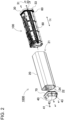
- FIG. 4 is an exploded perspective view of core block 100 shown in FIG. 2 .
- FIG. 5 is an exploded perspective view of core block 100 shown in FIG. 4 .
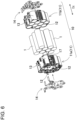
- FIG. 6 is an exploded perspective view of battery block 10 shown in FIG. 5 .
- FIG. 7 is a vertical sectional view along line VII-VII of power source device 1000 taken along line VII -VII shown in FIG. 1 .
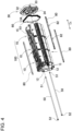
- FIG. 8 is a schematic horizontal sectional view of power source device 1000 according to Embodiment 1 of the present disclosure.
- FIG. 9 is a horizontal sectional view of power source device 1000 taken along line IX-IX shown in FIG. 1 .
- FIG. 10 is a horizontal sectional view with an enlarged sectional view of a main part of power source device 1000 along line X-X shown in FIG. 1 .
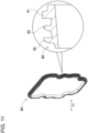
- FIG. 11 is a perspective view with an enlarged sectional view of a main part of first seal 60 shown in FIG. 4 .
- FIG. 12 is an enlarged plan view of second seal 70 shown in FIG. 3 .
- Power source device 1000 illustrated in these figures includes core block 100, outer case 20, first lid 30, and second lid 40.
- Outer case 20 has a rod shape extended in one direction as illustrated in FIG. 1 .
- Outer case 20 is a tubular casing with opening at both ends thereof, and core block 100 illustrated in FIG. 2 and FIG. 3 is inserted in outer case 20.
- First open end 21 at one and out of open ends of outer case 20 is closed with first lid 30.
- Second open end 22 on an opposite end of the first open end 21 is closed with second lid 40.
- core block 100 includes battery blocks 10 connected to one another in connecting direction Dc. Battery blocks 10 are stacked on one another and connected to one another with shafts 50. As illustrated in FIG. 6 and FIG. 7 , each battery block 10 includes battery holder 11 for holding battery cells 1. Battery holder 11 causes battery cells 1 to be arranged at predetermined positions. Battery cells 1 held in each battery block 10 are connected in series or parallel to one another.
- each battery block 10 has holder through-holes 12 provided therein.
- shafts 50 are inserted in holder through-holes 12 that are connected such that holder through-holes 12 are aligned in each of battery blocks 10 connected in one direction.
- Screw threads 51 are formed on at least at respective tips of shafts 50.
- First lid 30 is fixed with screw thread 51 formed at the tip of each shaft 50 such that shafts 50 are inserted in core block 100.
- core block 100 is fixed onto first lid 30 with shafts 50 that pass through core block 100 in which battery blocks 10 are connected to one another.
- time needed for individually fixing each battery block 10 can be saved.
- the exemplary embodiment has an advantage that core block 100 accommodated in outer case 20 is stably fixed. Stable fixing of core block 100 inside outer case 20 prevents a breakage of or a damage to internal components even when an external force, such as dropping or vibration, is applied to power source device 1000.
- a fastening method using an E-ring or push nut has been known as a method of fastening the core block accommodated in the outer case.
- this method requires complicated machining.
- the battery blocks may be fixed from outside with a screw by forming a hole in the outer case.
- this method also requires a large working man-hours and additional waterproofing.
- the core block may be fixed by fastening the shaft and nut.
- this method requires a time-consuming work of mounting the shaft onto the nut.
- shafts 50 passing through battery blocks 10 connect even first lid 30 as described above.
- Core block 100 fixed onto first lid 30 is inserted into outer case 20 so that core block 100 is firmly fixed with first lid 30 having a large area.
- Outer case 20 includes, as illustrated in FIGS. 1-3 , outer case 20 having a tubular shape with open both ends, first lid 30 closing first open end 21 at one of the open both ends of outer case 20, and second lid 40 closing second open end 22.
- core block 100 is inserted into outer case 20 such that first lid 30 is fixed onto core block 100, and first lid 30 is fixed onto outer case 20 by first screws 31.
- second lid 40 is fixed onto outer case 20 with second screws 41.
- Outer case 20 has a substantially rectangular cross section, and has substantially a rectangular tubular shape with open both ends. Four corners of the rectangular tubular shape of outer case 20 are chamfered to have curved surfaces. Outer case 20 with this shape is a rectangular tubular outer case 20 with curved corners, thus providing preferable appearance and gentle touch.
- a cross-section of first lid 30 and second lid 40 has a shape that follows an outer shape of outer case 20 so that first lid 30 and second lid 40 can close first open end 21 and second open end 22 of outer case 20 with good appearance, respectively.
- First lid 30 and second lid 40 have first step wall 32 and second step wall 42 that are inserted in first open end 21 and second open end 22 of outer case 20, respectively. While first step wall 32 and second step wall 42 are inserted inside of first open end 21 and second open end 22 of outer case 20, respectively, first step wall 32 and second step wall 42 contact inner surfaces of first open end 21 and second open end 22 of outer case 20 to close these first open end 21 and second open end 22, respectively.
- first lid 30 and second lid 40 outer shapes of first step wall 32 and second step wall 42 are slightly smaller than an inner shape of outer case 20. Outer shapes of first step wall 32 and second step wall 42 are substantially same or slightly larger than the outer shape of outer case 20.
- First lid 30 and second lid 40 close first open end 21 and second open end 22, respectively, with contact surfaces of first lid 30 and second lid 40 on outer sides of first step wall 32 and second step wall 42 contact first open end 21 and second open end 22 of outer case 20.
- First step wall 32 and second step wall 42 on first lid 30 and second lid 40 position first lid 30 and second lid 40 and connect first lid 30 and second lid 40 to outer case 20.
- first seal 60 and second seal 70 are provided on outer peripheral surfaces of first step wall 32 and second step wall 42 of first lid 30 and second lid 40.
- Outer case 20 is connected to first lid 30 and second lid 40 in a sealed structure via ring-like first seal 60 and second seal 70 disposed on the outer peripheral surfaces of first step wall 32 and second step wall 42.
- first seal 60 and second seal 70 are integrally formed into a shape that consecutively bend from first open end 21 and second open end 22, respectively, to their inner surfaces.
- First seal 60 having this shape is provided from an interface between first lid 30 and first step wall 32 to an interface between the outer peripheral surface of first step wall 32 and an outer peripheral surface of first open end 21.
- Second seal 70 having this shape is provided from an interface between second lid 40 and second step wall 42 to an interface between the outer peripheral surface of second step wall 42 and an outer peripheral surface of second open end 22.
- First seal 60 and second seal 70 are pressed and elastically crushed at these interfaces to maintain a watertight state, thereby providing a stable sealing effect.
- a discharge connector for discharging from built-in battery cells and a charge connector for charging built-in battery cells 1 may be provided at second lid 40.
- a display on the surface for displaying a remaining capacity of power source device 1000 may be provided on first lid 30 or second lid 40. This display indicates, for example, the remaining capacity of the power source device by a lighting state of a light source, such as an LED.
- First lid 30 is fixed onto outer case 20 with first screws 31, as illustrated in FIG. 10 .
- First lid 30 is fixed onto outer case 20 such that first lid 30 is previously fixed onto core block 100 with shafts 50.
- core block 100 onto which first lid 30 is fixed is inserted from of first open end 21 of outer case 20.
- first lid 30 is fixed onto outer case 20 with first screws 31, as illustrated in FIG. 10 .
- First open end 21 of outer case 20 has first threaded hole 23 for screwing first screw 31.
- First lid 30 has first insertion hole 33 therein for inserting first screw 31.
- First insertion hole 33 may be a threaded hole.
- first lid 30 fixed to core block 100 onto outer case 20 thus fixes core block 100 firmly to outer case 20 via first lid 30.
- second lid 40 is fixed onto outer case 20 with second screws 41 while first lid 30 is fixed onto outer case 20.
- First screw 31 is disposed on an outer side of shafts 50 when viewed from an end surface of outer case 20. This arrangement provides waterproofing by closing first open end 21 of outer case 20 by first screws 31 via first seal 60 while fixing core block 100 inside outer case 20 by shafts 50.
- first seal 60 is disposed on an inner side of first screw 31 in outer case 20 when viewed from first open end 21.
- This arrangement waterproofs the inside of outer case 20 with first seal 60 tightly contacting the interface between first lid 30 and outer case 20 while first lid 30 is fixed onto outer case 20 with first screws 31. In other words, waterproofing at a position of first screw 31 is not necessary.
- the interface is sealed with first seal 60 pressed and deformed by first open end 21 of outer case 20 and first lid 30 so as to prevent water immersion into outer case 20.
- FIG. 11 is a perspective view of first seal 60.
- First seal 60 has an annular shape and is bent to avoid first insertion hole 33 provided in first lid 30. This shape allows first seal 60 to be disposed on the inner side of first screw 31 in outer case 20. Still more, first seal 60 includes first flange 61 protruding outward along the annular shape. As illustrated in an enlarged sectional view of a main part in FIG. 10 , first flange 61 is elastically deformed by being sandwiched between first lid 30 and first open end 21 so as to provide waterproofing on the interface between first open end 21 and first lid 30.
- First seal 60 includes first pleat 62 that is substantially parallel with first flange 61 and has an outer periphery smaller than first flange 61.
- First pleat 62 protrudes outward from first seal 60 with the annular shape.
- Plural first pleats 62 parallel to each other may be provided.
- Pleats 62 protrude from the inner surface of outer case 20 and elastically deform when first seal 60 is press-fitted to first open end 21, as illustrated in FIG. 10 .
- This structure of first seal 60 prevents water following from first open end 21 to the inner surface of outer case 20 from entering inside outer case 20, as illustrated in FIG. 10 , even when water immersion beyond first flange 61 is supposed to occur.
- pleats 62 enhances the waterproof performance.
- double first pleats 62 enhance reliability of waterproof performance.
- the number of first pleats 62 may be one or three more depending on required waterproof performance.
- Thermoplastic elastomer (TPE) is suitable for first seal 60.
- Second open end 22 of outer case 22 has second threaded hole 24 for screwing second screw 41.
- Second lid 40 has second insertion hole 43 therein for inserting second screw 41.
- Second insertion hole 43 may be a threaded hole.
- Second screw 41 is disposed on the outer side of shafts 50 when viewed from the end surface of outer case 20. This arrangement provides waterproofing by closing second open end 22 of outer case 20 with second screw 41 via second seal 70 while fixing core block 100 inside outer case 20 by shafts 50.
- second seal 70 is interposed between second lid 40 and outer case 20 so as to provide waterproofing on this interface.
- Second seal 70 is disposed on an inner side of the second threaded hole in outer case 20 when viewed from second open end 22. This arrangement waterproofs the inside of outer case 20 with second seal 70 tightly contacting the interface between second lid 40 and outer case 20 while second lid 40 is fixed onto outer case 20 by second screw 41.
- second seal 70 includes second flange 71 and second pleat 72. As illustrated in an enlarged sectional view of a main part in FIG. 10 , second seal 70 provides waterproofing on this interface by being interposed between second lid 40 and outer case 20 when second lid 40 is fixed by second screw onto outer case 20 to which first lid 30 is fixed.
- second seal 70 includes protrusion 74 protruding in connecting direction Dc of battery blocks 10 toward the interface with outer case 20.
- protrusion 74 elastically deforms and fills a gap when second lid 40 is fixed onto outer case 20 with second screw 41.
- the gap tends to be generated due to accumulated tolerance when core block 10 becomes long such as by connecting a battery blocks 10. Therefore, second seal 70 including protrusion 74 protruding in a stacking direction of battery blocks 10, i.e., an extending direction of shafts 50, suppresses generation of the gap due to protrusion 74 elastically deforming when second seal 70 is sandwiched.
- second seal 70 may be made of TPE.
- Shaft 50 linearly connects battery blocks 10 configuring core block 100.
- Shaft 50 illustrated in FIG. 4 and FIG. 9 includes screw head 52 at a rear end thereof and screw thread 51 at the tip thereof, and has a total length sufficient for connecting three battery blocks 10.
- Shaft 50 is preferably made of metal to secure the strength for fastening and connecting battery blocks 10 to one another from both sides.
- Metal shaft 50 has a large heat capacity and effectively absorbs and transfers heat even when battery cell 1 generates heat.
- Shaft 50 as described above is inserted in holder through-hole 12 provided in battery holder 11 of each battery block 10 to integrally connect battery blocks 10 linearly arranged.
- Insert nut 34 is embedded in first lid 30. Insert nut 34 is engaged with screw thread 51 formed at the tip of each shaft 50 while shafts 50 are inserted in core block 100. This structure securely connects the tip to first lid 30 by insert nut 34 even when shaft 50 is long. As a result, stable connection of battery blocks 10 is achieved. Insert nut 34 is insert-molded in first lid 30.
- screw thread 51 only at the tip of shaft 50.
- the screw thread may be formed over an entire length of the shaft. This structure advantageously firmly connects the battery blocks to one another.
- the above example describes an example of embedding insert nut 34 in first lid 30, and insert nut 34 is engaged with screw thread 51 formed at the tip of each shaft 50.
- This structure stably fixes first lid 30 by using long shaft 50 even when the core block is long due to a lot of battery blocks 10 or battery cells 1.
- the present invention is not limited to this structure.
- a tapping screw may be formed at the tip of shaft 50 and the tapping screw may be screwed into first lid 30.
- the core block is stably fixed by the tapping screw because shaft 50 with shorter length can be used to reduce fluctuation at the tip.
- This example is illustrated in a schematic horizontal sectional view in FIG. 13 as power source device 2000 according to Exemplary Embodiment 2.
- components identical to those of Embodiment 1 are denoted by the same reference numerals and their detailed description will be omitted.
- core block 100B includes two battery blocks 10.
- the total length of shaft 50B is smaller than the device according to Embodiment 1.
- a tip of shaft 50B is the tapping screw where screw thread 51B is formed like a wood screw. Short shaft 50B easily positions screw thread 51B at the tip onto first lid 30B. Accordingly, first lid 30 is stably fixed by directly screwing the tapping screw.
- Core block 100 is accommodated in outer case 20 while battery blocks 10 are stacked on one another in an axial direction of outer case 20.
- battery blocks 10 each including battery cells 1 arranged in multiple stages and rows in battery holder 11 are stacked on one another lengthwise that is a longer direction of battery cells 1, and linearly connected to one another.
- core block 100 includes three battery blocks 10.
- Core block 100 has a large battery capacity [Ah] by connecting battery cells 1 in parallel to one another, and increases an output voltage [V] by connecting battery cells 1 in series to one another.
- the power source device of the present disclosure is not limited to three battery blocks 10 that configure the core block, and two or less battery blocks 10 may be included or four or more battery blocks 10 may be included depending on the purpose of use and specifications.
- battery holder 11 includes insertion tube 13 for battery cell 1, and battery cell 1 is inserted in insertion tube 13 so as to be disposed battery cells 1 in predetermined positions.
- rechargeable battery cells 1 are arranged in multiple stages and rows in battery holder 11.
- Each battery cell 1 is a rechargeable cylindrical secondary battery, and a lithium-ion secondary battery is preferably used. However, the present invention does not specify the use of lithium-ion secondary battery for the battery cell.
- Other rechargeable secondary batteries such as a nickel-hydrogen battery, a nickel-cadmium battery, and lithium-polymer battery, may be used.
- battery cells 1 are arranged in parallel such that longitudinal directions of battery cells 1 are directed in the same direction.
- Battery cells 1 that configure battery block 10 are connected in parallel or series to one another for the required number by lead plates 14 connected to end electrodes on both ends of battery cells 1, and connected to circuit board 16 via wiring board 15 as illustrated in FIG. 5 .
- core block 100 three battery blocks 10 each including ten battery cells 1 are connected to one another.
- thirty battery cells 1 are connected in three parallel and ten series connections. The number of battery cells and a connection may be changed as appropriate in core block 100.
- Battery holder 11 is prepared by molding insulating plastic to have the same shape. Insertion tubes 13 for battery cells 1 and connecting protrusions 17 for connecting shafts 50 are provided by integral molding.
- Insertion tube 13 holds battery cell 1 placed in insertion tube 13 at the predetermined position.
- Battery holder 11 in the drawings has a shape for holding the cylindrical batteries as battery cells 1 by inserting the cylindrical batteries into insertion tubes 13.
- the battery cell is not limited to the cylindrical battery in the present invention.
- the battery cell may be a rectangular battery.
- the insertion tube of the battery holder has a rectangular tubular shape.
- battery holder 11 illustrated in FIG. 7 ten battery cells 1 are arranged in four vertical stages, and three rows, two rows, three rows, and two rows of battery cells are arranged in respective stages from the top. Battery cells 1 are heaped while alternately deviated in which battery cells 1 are vertically arranged between horizontally adjacent battery cells 1.
- battery holder 11 is split and molded in a pair of cell holders 11a and 11b.
- Each of cell holders 11a and 11b configuring battery holder 11 includes insertion tubes 13 for inserting battery cells 1 in parallel to each other.
- Insertion tube 13 has open both ends so that end electrodes of the cylindrical battery inserted in insertion hole 13 are exposed to connect lead plates 14 to the end electrodes.
- Insertion tubes 13 of cell holders 11a and 11b have a length to insert a half of battery cell 1. In each battery cell 1, a half of battery cell 1 is inserted in one cell holder 11a and remaining half is inserted in the other cell holder 11b to arrange battery cell 1 at the predetermined position in battery holder 11.
- Power source device 1000 includes board holder 18 and circuit board 16 held by board holder 18.
- Board holder 18 is one end surface of core block 100, and arranged on the end surface of core block 100 facing second lid 40.
- Board holder 18 has holder insertion holes therein into which insert shafts 50 are inserted. Shafts 50 are inserted from the holder insertion holes of board holder 18 and screw heads are positioned on the side of board holder 18, respectively. In other words, shafts 50 are fixed by placing screw heads 52 on board holder 18.
- Core block 100 further includes circuit board 16 connected to battery blocks 10.
- circuit board 16 is disposed on the end surface of battery blocks 10 linearly connected to one another.
- Circuit board 16 is arranged at the predetermined position via board holder 18.
- Lead plates 14 connected to battery cells 1 are connected directly or via wiring board 15 to circuit board 16.
- Electronic components that configure a protective circuit for controlling charging or discharging of battery cell 1 are mounted on circuit board 16.
- the protective circuit detects voltage of each battery, and a circuit for shutting off charging or discharging current is also provided.
- a temperature detection circuit for detecting abnormal temperature of battery cells 1 may be mounted on circuit board 16.
- the power source device may further include one or more side elastic bodies 80 between a side surface of core block 100 and an inner surface of outer case 20.
- Side elastic body 80 suppresses a damage when core block 100 collides with an inner wall of outer case 20 inside outer case 20 due to an impact applied to the side surface of the power source device.
- side elastic body 80 has a rod shape extending in connecting direction Dc of battery block 10.
- the device may preferably include plural side elastic bodies 80.
- Side elastic bodies 80 are disposed, for example, between the inner surface of outer case 20 and each of both side surfaces of core block 100. This arrangement protects core block 100 inside outer case 20 from impacts applied to both left and right side surfaces.
- Side elastic body 80 may be made of rubber material with high elasticity, such as fluororubber, isoprene rubber, styrene butadiene rubber, butadiene rubber, chloroprene rubber, nitrile rubber, hydrogenated nitrile rubber, polyisobutylene rubber, ethylene propylene rubber, ethylene-vinyl acetate copolymer rubber, chlorosulfonated polyethylene rubber, acryl rubber, epichlorohydrin rubber, urethane rubber, silicone rubber, thermoplastic olefin rubber, ethylene propylene diene rubber, butyl rubber, and polyether rubber.
- fluororubber isoprene rubber, styrene butadiene rubber, butadiene rubber, chloroprene rubber, nitrile rubber, hydrogenated nitrile rubber, polyisobutylene rubber, ethylene propylene rubber, ethylene-vinyl acetate copolymer rubber, chlorosulfonated polyethylene rubber,
- Side elastic body 80 preferably has narrow portion 82 with locally narrowed width provided in connecting direction Dc of battery blocks 10. This structure facilitates a work of press-fitting core block 100 into outer case 20 by partially reducing pressure at narrow portion 82.
- a method for manufacturing the power source device as configured above will be described. First, holder through-holes 12 opening in each battery block 10 are aligned and battery blocks 10 are connected to one another in one direction. Then, shafts 50 are inserted in holder through-holes 12. Screw thread 51 formed at least at the tip of each shaft 50 is screwed and fixed to first lid 30 arranged on the end surface of core block 100. In this state, core block 100 is inserted from first open end 21 that is one open end of outer case 20 so that first lid 30 may close first open end 21. Then, second open end 22 that is the other open end of outer case 20 is closed by second lid 40. Shafts 50 passing through core block 100 in which battery blocks 10 are connected thus fix core block 100 onto first lid 30.
- Core block 100 accommodated in outer case 20 is stably fixed. Accordingly, stable fixing of core block 100 inside outer case 20 prevents a breakage of or damage to internal components even when an external force such as dropping or vibration is applied to the power source device.
- a power source device and a method for manufacturing the power source device according to the present disclosure are effectively applicable to a power source device installed in power vehicles to supply power to a drive motor, such as a driving power source for power-assisted bicycles, motor bikes, electric wheel chairs, electric tricycles, and electric carts.
- a drive motor such as a driving power source for power-assisted bicycles, motor bikes, electric wheel chairs, electric tricycles, and electric carts.
Landscapes
- Chemical & Material Sciences (AREA)
- Chemical Kinetics & Catalysis (AREA)
- Electrochemistry (AREA)
- General Chemical & Material Sciences (AREA)
- Engineering & Computer Science (AREA)
- Microelectronics & Electronic Packaging (AREA)
- Manufacturing & Machinery (AREA)
- Power Engineering (AREA)
- Battery Mounting, Suspending (AREA)
Abstract
Description
- The present disclosure relates to a power source device including battery cells and a method for manufacturing the power source device.
- A power source device including battery cells connected in series or parallel is employed as a driving power source for a mobile object, such as a power-assisted bicycle, an electric cart, and an electric scooter; a power tool, a vacuum cleaner, and so on. This type of power source device often has a structure of connecting battery blocks each including battery cells connected in series or parallel (PTL 1).
- A method for connecting the battery blocks is to fix a core block by fastening a shaft and a nut. However, this method requires a time-consuming work of mounting the shaft onto the nut.
- Another method is to fix the battery blocks to each other by direct screwing. However, this method also has a problem of an increase in work man-hours corresponding to the number of battery blocks.
- PTL 1:
Japanese Patent Laid-Open Publication No. 2011-134540 - An object of the present disclosure is to provide a power source device and a method for manufacturing the power source device that facilitate connection of battery blocks and fixing of the battery blocks onto an outer case.
- To achieve the above object, a power source device according to an aspect of the present disclosure includes: battery blocks each including battery cells connected in series or parallel to one another, each of the battery blocks having holder through-holes therein; shafts inserted in the holder through-holes of the each of the battery blocks, respectively, such that the holder through-holes in the each of the battery blocks are aligned to the holder through-holes in another battery block of the battery blocks connected to one another in a connecting direction; an outer case accommodating the battery blocks therein, the outer case having a tubular shape with both ends opening to have a first open end and a second open end; a first lid closing the first open end of the outer case; and a second lid closing the second open end of the outer case. The shafts have screw threads at least at respective tips thereof. The battery blocks connected in the connecting direction constitutes a core block. The first lid is fixed with the screw threads of the shafts such that the shafts are inserted in the holder through-holes of the each of the battery blocks in the core block, respectively.
- In a method for manufacturing a power source device according to another aspect, battery blocks each of which includes battery cells connected in series or parallel to one another is prepared. A core block is formed by inserting of shafts in holder through-holes, respectively, such that the holder though-holes opening in the each of the battery blocks are aligned with the holder though-holes of another battery block of the battery blocks connected to one another in a connecting direction, and by screwing and fixing screw threads provided at least at respective tips of the shafts to a first lid provided on an end surface of the core block. An outer case having both ends opening to have a first open end and a second open end is prepared. The core block is inserted from the first open end on one end of the outer case. The second open end of the outer case is closed with a second lid.
- In the power source device and the method for manufacturing the power source device according to the aspect, the core block is fixed onto the first lid with the shafts passing through the core block in which the battery blocks are connected. Accordingly, time needed for fixing each of the battery blocks individually can be saved. In addition, the core block housed in the outer case can be stably fixed. Stable fixing of the core block inside the outer case prevents a breakage of or damage to internal components even when an external force such as dropping or vibration is applied to the power source device.
-
-
FIG. 1 is a perspective view of a power source device according toExemplary Embodiment 1 of the present disclosure. -
FIG. 2 is an exploded perspective view of the power source device shown inFIG. 1 . -
FIG. 3 is an exploded perspective view of the power source device inFIG. 2 viewed from the back. -
FIG. 4 is an exploded perspective view of a core block shown inFIG. 2 . -
FIG. 5 is an exploded perspective view of the core block shown inFIG. 4 . -
FIG. 6 is an exploded perspective view of a battery block shown inFIG. 5 . -
FIG. 7 is a vertical sectional view of the power source device taken along line VII-VII shown inFIG. 1 . -
FIG. 8 is a schematic horizontal sectional view of the power source device according toEmbodiment 1 of the disclosure. -
FIG. 9 is a horizontal sectional view of the power source device taken along line IX-IX shown inFIG. 1 . -
FIG. 10 is a horizontal sectional view with an enlarged sectional view of a main part along line X - X of the power source device taken along line X-X shown inFIG. 1 . -
FIG. 11 is a perspective view with an enlarged sectional view of a main part of a first seal shown inFIG. 4 . -
FIG. 12 is a front view of a second seal shown inFIG. 3 . -
FIG. 13 is a schematic horizontal sectional view of a power source device according to Exemplary Embodiment 2 of the present disclosure. - Exemplary embodiments of the present disclosure may be specified by the following structure and characteristic.
- In a power source device according to another aspect of the present disclosure, in any of the above aspects, insert nuts are embedded in the first lid. The insert nuts are engaged with the screw threads of the shafts such that the shafts are inserted in the holder through-holes in the core block, respectively. This structure securely connects the tip to the first lid with the insert nut also for a long shaft, and thus stable connection of the battery blocks is achieved.
- A power source device according to still another aspect of the present disclosure, in any of the above aspects, further includes first screws fixing the first lid to the first open end of the outer case such that the core block to which the first lid is fixed with the shafts is inserted in the outer case from the first open end. The outer case has first threaded holes therein at an end rim of the first open end, and the first screws are screwed to the first threaded holes, respectively. This structure advantageously securely fixes the core block to the outer case via the first lid.
- A power source device according to still another aspect of the present disclosure, in any of the above aspects, further includes a first seal provided at an interface between the first lid and the outer case. The first seal is disposed closer to an inner surface of the outer case than the plurality of first threaded holes when viewed from the first open end. This structure waterproofs the inside of the outer case with the first seal tightly contacting the interface between the first lid and the outer case while the first lid is fixed onto the outer case with the first screws.
- In a power source device according to still another aspect of the present disclosure, in any of the above aspects, the first screws are disposed on an outer side of the shafts when viewed from an end surface of the outer case. This structure waterproofs by closing the first open end of the outer case with the first screws via the first seal while the core block inside the outer case is fixed by the shafts.
- A power source device according to still another aspect of the present disclosure, in any of the above aspects, further includes second screws fixing the second lid pressing the core block onto the second open end of the outer case such that the core block to which the first lid is fixed with the shafts is inserted in the outer case from the first open end. The outer case has second threaded holes at an end rim of the second open end, and the second screws are screwed to the second threaded holes, respectively. This structure efficiently performs an assembly process since the core block onto which the first lid is fixed is inserted in the outer case and fixed onto the second lid.
- A power source device according to still another aspect of the present disclosure, in any of the above aspects, further includes a second seal provided at an interface between the second lid and the outer case. The second seal is disposed on an inner side of the second threaded holes in the outer case when viewed from the second open end. This structure waterproofs the inside of the outer case with the second seal tightly contacting the interface between the second lid and the outer case while that the second lid is fixed onto the outer case by the second screws.
- In a power source device according to still another aspect of the present disclosure, in any of the above aspects, the second seal includes a protrusion protruding in the connecting direction toward an interface between the outer case and the second seal. This structure allows a gap filled with the protrusion with elastic deformation when the second lid is fixed onto the outer case with the second screw.
- In a power source device according to still another aspect of the present disclosure, in any of the above aspects, the second screws are arranged on the outer side of the shafts when viewed from the end face of the outer case. This structure waterproofs with the second open end of the outer case closed with the second screws via the second seal while the core block inside the outer case is fixed with the shafts.
- A power source device according to still another aspect of the present disclosure, in any of the above aspects, further includes: a board holder disposed on one end surface of the core block in which the battery blocks is connected, the one end face facing the second lid; and a circuit board held by the board holder. The board holder has holder insertion holes therein into which the shafts are inserted, respectively. The shafts include screw heads on respective opposite sides of the screw threads. The shafts are inserted from the holder insertion holes of the board holder, respectively. The screw heads are placed and fixed to the board holder. In other words, the shafts have the screw heads on respective opposite sides of the screw threads. A distance between the board holder and each of the screw heads is shorter than a distance between the board holder and each of the screw threads.
- A power source device according to still another aspect of the present disclosure, in any of the above aspects, further includes a side elastic body disposed between a side surface of the core block and an inner surface of the outer case, the side elastic body extending in the connecting direction. This structure suppresses a damage even when the core block inside the outer case collides with an inner wall of the outer case due to an impact applied to the side surface of the power source device.
- In a power source device according to still another aspect of the present disclosure, in any of the above aspects, the side elastic body includes a narrow portion having locally narrowed width in the connecting direction. This structure has an advantage of facilitating a work of press-fitting the core block into the outer case by partially reducing a pressure at the narrow portion.
- Exemplary embodiments of the present disclosure will be described below with reference to the drawings. Note that the following exemplary embodiments are merely examples for embodying a technical concept of the present invention, and thus the present invention is not limited to the following exemplary embodiments. Still more, the present specification does not intend to limit components described in the scope of appended claims to those described in the exemplary embodiments. In particular, unless otherwise specifically described, dimensions, materials, shapes, and their relative arrangements described in the exemplary embodiments are merely examples and not intended to limit the scope of the present invention. Still more, sizes and positional relationship of components in the drawings may be exaggerated for clear recognition. Still more, same names and reference marks in the following description denote the same or equivalent components to omit detailed description where appropriate. Furthermore, a plurality of elements configuring the present disclosure may be achieved by one component to serve as the plurality of elements, or a function of one component may be distributed to a plurality of components.
- The power source device of the present disclosure increases voltage or capacity by connecting numerous battery cells in series or parallel to offer a driving power source suitable for mobile objects such as power-assisted bicycles, electric bicycles, motor bikes, electric wheelchairs, electric tricycles, and electric carts. Still more, the power source device may also be used as a power source for a range of electric appliances used indoors and outdoors such as electric cleaners and power tools. Furthermore, the power source device may be used for a range of purposes such as a backup power source for server, a power source installed in an electric vehicle, such as a hybrid vehicle and an electric car, to supply power to a running motor, a power source for storing power generated by natural energy, such as solar power generation and wind power generation, or a storage power source for storing midnight power or balancing power load at a power peak. Hereinafter, a battery pack for power-assisted bicycle is given as an example of the power source device according to the exemplary embodiments described below.
-
FIGS. 1-12 illustratepower source device 1000 according toExemplary Embodiment 1 of the present disclosure.FIG. 1 is a perspective view ofpower source device 1000 according toEmbodiment 1 of the present disclosure.FIG. 2 is an exploded perspective view ofpower source device 1000 shown inFIG. 1 .FIG. 3 is an exploded perspective view ofpower source device 1000 shown inFIG. 2 viewed from the back.FIG. 4 is an exploded perspective view ofcore block 100 shown inFIG. 2 .FIG. 5 is an exploded perspective view ofcore block 100 shown inFIG. 4 .FIG. 6 is an exploded perspective view ofbattery block 10 shown inFIG. 5 .FIG. 7 is a vertical sectional view along line VII-VII ofpower source device 1000 taken along line VII -VII shown inFIG. 1 .FIG. 8 is a schematic horizontal sectional view ofpower source device 1000 according toEmbodiment 1 of the present disclosure.FIG. 9 is a horizontal sectional view ofpower source device 1000 taken along line IX-IX shown inFIG. 1 .FIG. 10 is a horizontal sectional view with an enlarged sectional view of a main part ofpower source device 1000 along line X-X shown inFIG. 1 .FIG. 11 is a perspective view with an enlarged sectional view of a main part offirst seal 60 shown inFIG. 4 .FIG. 12 is an enlarged plan view ofsecond seal 70 shown inFIG. 3 .Power source device 1000 illustrated in these figures includescore block 100,outer case 20,first lid 30, andsecond lid 40. -
Outer case 20 has a rod shape extended in one direction as illustrated inFIG. 1 .Outer case 20 is a tubular casing with opening at both ends thereof, andcore block 100 illustrated inFIG. 2 andFIG. 3 is inserted inouter case 20. Firstopen end 21 at one and out of open ends ofouter case 20 is closed withfirst lid 30. Secondopen end 22 on an opposite end of the firstopen end 21 is closed withsecond lid 40. - As illustrated in
FIGS. 2-5 ,core block 100 includes battery blocks 10 connected to one another in connecting direction Dc. Battery blocks 10 are stacked on one another and connected to one another withshafts 50. As illustrated inFIG. 6 andFIG. 7 , eachbattery block 10 includesbattery holder 11 for holdingbattery cells 1.Battery holder 11 causesbattery cells 1 to be arranged at predetermined positions.Battery cells 1 held in eachbattery block 10 are connected in series or parallel to one another. - In addition, each
battery block 10 has holder through-holes 12 provided therein. As illustrated inFIG. 4 ,shafts 50 are inserted in holder through-holes 12 that are connected such that holder through-holes 12 are aligned in each of battery blocks 10 connected in one direction.Screw threads 51 are formed on at least at respective tips ofshafts 50. -
First lid 30 is fixed withscrew thread 51 formed at the tip of eachshaft 50 such thatshafts 50 are inserted incore block 100. In this structure, as illustrated inFIG. 8 ,core block 100 is fixed ontofirst lid 30 withshafts 50 that pass throughcore block 100 in which battery blocks 10 are connected to one another. Thus, time needed for individually fixing eachbattery block 10 can be saved. The exemplary embodiment has an advantage thatcore block 100 accommodated inouter case 20 is stably fixed. Stable fixing ofcore block 100 insideouter case 20 prevents a breakage of or a damage to internal components even when an external force, such as dropping or vibration, is applied topower source device 1000. - A fastening method using an E-ring or push nut has been known as a method of fastening the core block accommodated in the outer case. However, this method requires complicated machining. The battery blocks may be fixed from outside with a screw by forming a hole in the outer case. However, this method also requires a large working man-hours and additional waterproofing. Still more, the core block may be fixed by fastening the shaft and nut. However, this method requires a time-consuming work of mounting the shaft onto the nut. In contrast, in
power source device 1000 according to the embodiment,shafts 50 passing through battery blocks 10 connect evenfirst lid 30 as described above.Core block 100 fixed ontofirst lid 30 is inserted intoouter case 20 so thatcore block 100 is firmly fixed withfirst lid 30 having a large area. Each component will be detailed below. -
Outer case 20 includes, as illustrated inFIGS. 1-3 ,outer case 20 having a tubular shape with open both ends,first lid 30 closing firstopen end 21 at one of the open both ends ofouter case 20, andsecond lid 40 closing secondopen end 22. As illustrated inFIG. 3 ,core block 100 is inserted intoouter case 20 such thatfirst lid 30 is fixed ontocore block 100, andfirst lid 30 is fixed ontoouter case 20 byfirst screws 31. Then, as illustrated inFIG. 2 ,second lid 40 is fixed ontoouter case 20 withsecond screws 41. -
Outer case 20 has a substantially rectangular cross section, and has substantially a rectangular tubular shape with open both ends. Four corners of the rectangular tubular shape ofouter case 20 are chamfered to have curved surfaces.Outer case 20 with this shape is a rectangular tubularouter case 20 with curved corners, thus providing preferable appearance and gentle touch. - A cross-section of
first lid 30 andsecond lid 40 has a shape that follows an outer shape ofouter case 20 so thatfirst lid 30 andsecond lid 40 can close firstopen end 21 and secondopen end 22 ofouter case 20 with good appearance, respectively.First lid 30 andsecond lid 40 havefirst step wall 32 andsecond step wall 42 that are inserted in firstopen end 21 and secondopen end 22 ofouter case 20, respectively. Whilefirst step wall 32 andsecond step wall 42 are inserted inside of firstopen end 21 and secondopen end 22 ofouter case 20, respectively,first step wall 32 andsecond step wall 42 contact inner surfaces of firstopen end 21 and secondopen end 22 ofouter case 20 to close these firstopen end 21 and secondopen end 22, respectively. More specifically, infirst lid 30 andsecond lid 40, outer shapes offirst step wall 32 andsecond step wall 42 are slightly smaller than an inner shape ofouter case 20. Outer shapes offirst step wall 32 andsecond step wall 42 are substantially same or slightly larger than the outer shape ofouter case 20.First lid 30 andsecond lid 40 close firstopen end 21 and secondopen end 22, respectively, with contact surfaces offirst lid 30 andsecond lid 40 on outer sides offirst step wall 32 andsecond step wall 42 contact firstopen end 21 and secondopen end 22 ofouter case 20.First step wall 32 andsecond step wall 42 onfirst lid 30 andsecond lid 40 positionfirst lid 30 andsecond lid 40 and connectfirst lid 30 andsecond lid 40 toouter case 20. - As illustrated in
FIG. 2 andFIG. 3 , ring-likefirst seal 60 andsecond seal 70 are provided on outer peripheral surfaces offirst step wall 32 andsecond step wall 42 offirst lid 30 andsecond lid 40.Outer case 20 is connected tofirst lid 30 andsecond lid 40 in a sealed structure via ring-likefirst seal 60 andsecond seal 70 disposed on the outer peripheral surfaces offirst step wall 32 andsecond step wall 42. As illustrated inFIG. 9 andFIG. 10 ,first seal 60 andsecond seal 70 are integrally formed into a shape that consecutively bend from firstopen end 21 and secondopen end 22, respectively, to their inner surfaces.First seal 60 having this shape is provided from an interface betweenfirst lid 30 andfirst step wall 32 to an interface between the outer peripheral surface offirst step wall 32 and an outer peripheral surface of firstopen end 21.Second seal 70 having this shape is provided from an interface betweensecond lid 40 andsecond step wall 42 to an interface between the outer peripheral surface ofsecond step wall 42 and an outer peripheral surface of secondopen end 22.First seal 60 andsecond seal 70 are pressed and elastically crushed at these interfaces to maintain a watertight state, thereby providing a stable sealing effect. - A discharge connector for discharging from built-in battery cells and a charge connector for charging built-in
battery cells 1 may be provided atsecond lid 40. A display on the surface for displaying a remaining capacity ofpower source device 1000 may be provided onfirst lid 30 orsecond lid 40. This display indicates, for example, the remaining capacity of the power source device by a lighting state of a light source, such as an LED. -
First lid 30 is fixed ontoouter case 20 withfirst screws 31, as illustrated inFIG. 10 .First lid 30 is fixed ontoouter case 20 such thatfirst lid 30 is previously fixed ontocore block 100 withshafts 50. As illustrated inFIG. 2 andFIG. 3 ,core block 100 onto whichfirst lid 30 is fixed is inserted from of firstopen end 21 ofouter case 20. Then,first lid 30 is fixed ontoouter case 20 withfirst screws 31, as illustrated inFIG. 10 . Firstopen end 21 ofouter case 20 has first threadedhole 23 for screwingfirst screw 31.First lid 30 hasfirst insertion hole 33 therein for insertingfirst screw 31.First insertion hole 33 may be a threaded hole. The structure of fixingfirst lid 30 fixed to core block 100 ontoouter case 20 thus fixescore block 100 firmly toouter case 20 viafirst lid 30. As illustrated inFIG. 2 ,second lid 40 is fixed ontoouter case 20 withsecond screws 41 whilefirst lid 30 is fixed ontoouter case 20. -
First screw 31 is disposed on an outer side ofshafts 50 when viewed from an end surface ofouter case 20. This arrangement provides waterproofing by closing firstopen end 21 ofouter case 20 byfirst screws 31 viafirst seal 60 while fixingcore block 100 insideouter case 20 byshafts 50. - As illustrated in
FIG. 10 ,first seal 60 is disposed on an inner side offirst screw 31 inouter case 20 when viewed from firstopen end 21. This arrangement waterproofs the inside ofouter case 20 withfirst seal 60 tightly contacting the interface betweenfirst lid 30 andouter case 20 whilefirst lid 30 is fixed ontoouter case 20 withfirst screws 31. In other words, waterproofing at a position offirst screw 31 is not necessary. The interface is sealed withfirst seal 60 pressed and deformed by firstopen end 21 ofouter case 20 andfirst lid 30 so as to prevent water immersion intoouter case 20. -
FIG. 11 is a perspective view offirst seal 60.First seal 60 has an annular shape and is bent to avoidfirst insertion hole 33 provided infirst lid 30. This shape allowsfirst seal 60 to be disposed on the inner side offirst screw 31 inouter case 20. Still more,first seal 60 includesfirst flange 61 protruding outward along the annular shape. As illustrated in an enlarged sectional view of a main part inFIG. 10 ,first flange 61 is elastically deformed by being sandwiched betweenfirst lid 30 and firstopen end 21 so as to provide waterproofing on the interface between firstopen end 21 andfirst lid 30.First seal 60 includesfirst pleat 62 that is substantially parallel withfirst flange 61 and has an outer periphery smaller thanfirst flange 61.First pleat 62 protrudes outward fromfirst seal 60 with the annular shape. Pluralfirst pleats 62 parallel to each other may be provided.Pleats 62 protrude from the inner surface ofouter case 20 and elastically deform whenfirst seal 60 is press-fitted to firstopen end 21, as illustrated inFIG. 10 . This structure offirst seal 60 prevents water following from firstopen end 21 to the inner surface ofouter case 20 from entering insideouter case 20, as illustrated inFIG. 10 , even when water immersion beyondfirst flange 61 is supposed to occur. In other words, pleats 62 enhances the waterproof performance. In particular, doublefirst pleats 62 enhance reliability of waterproof performance. The number offirst pleats 62 may be one or three more depending on required waterproof performance. Thermoplastic elastomer (TPE) is suitable forfirst seal 60. -
Outer case 20 onto whichfirst lid 30 is fixed as described above is fixed tosecond lid 40 withsecond screws 41. Sincesecond lid 40 is thus fixed in whilecore block 100 is fixed ontofirst lid 30 and inserted intoouter case 20, an assembly process is efficiently performed. Secondopen end 22 ofouter case 22 has second threadedhole 24 for screwingsecond screw 41.Second lid 40 hassecond insertion hole 43 therein for insertingsecond screw 41.Second insertion hole 43 may be a threaded hole. -
Second screw 41 is disposed on the outer side ofshafts 50 when viewed from the end surface ofouter case 20. This arrangement provides waterproofing by closing secondopen end 22 ofouter case 20 withsecond screw 41 viasecond seal 70 while fixingcore block 100 insideouter case 20 byshafts 50. - As illustrated in
FIG. 2 ,second seal 70 is interposed betweensecond lid 40 andouter case 20 so as to provide waterproofing on this interface.Second seal 70 is disposed on an inner side of the second threaded hole inouter case 20 when viewed from secondopen end 22. This arrangement waterproofs the inside ofouter case 20 withsecond seal 70 tightly contacting the interface betweensecond lid 40 andouter case 20 whilesecond lid 40 is fixed ontoouter case 20 bysecond screw 41. - Similarly to
first seal 60,second seal 70 includessecond flange 71 andsecond pleat 72. As illustrated in an enlarged sectional view of a main part inFIG. 10 ,second seal 70 provides waterproofing on this interface by being interposed betweensecond lid 40 andouter case 20 whensecond lid 40 is fixed by second screw ontoouter case 20 to whichfirst lid 30 is fixed. - As illustrated in
FIG. 12 ,second seal 70 includesprotrusion 74 protruding in connecting direction Dc of battery blocks 10 toward the interface withouter case 20. In this structure,protrusion 74 elastically deforms and fills a gap whensecond lid 40 is fixed ontoouter case 20 withsecond screw 41. In particular, the gap tends to be generated due to accumulated tolerance whencore block 10 becomes long such as by connecting a battery blocks 10. Therefore,second seal 70 includingprotrusion 74 protruding in a stacking direction of battery blocks 10, i.e., an extending direction ofshafts 50, suppresses generation of the gap due toprotrusion 74 elastically deforming whensecond seal 70 is sandwiched. Thus, a strength of fixing the core block is increased. Similarly tofirst seal 60,second seal 70 may be made of TPE. -
Shaft 50 linearly connects battery blocks 10 configuringcore block 100.Shaft 50 illustrated inFIG. 4 andFIG. 9 includesscrew head 52 at a rear end thereof andscrew thread 51 at the tip thereof, and has a total length sufficient for connecting three battery blocks 10.Shaft 50 is preferably made of metal to secure the strength for fastening and connecting battery blocks 10 to one another from both sides.Metal shaft 50 has a large heat capacity and effectively absorbs and transfers heat even whenbattery cell 1 generates heat.Shaft 50 as described above is inserted in holder through-hole 12 provided inbattery holder 11 of eachbattery block 10 to integrally connectbattery blocks 10 linearly arranged. -
Insert nut 34 is embedded infirst lid 30.Insert nut 34 is engaged withscrew thread 51 formed at the tip of eachshaft 50 whileshafts 50 are inserted incore block 100. This structure securely connects the tip tofirst lid 30 byinsert nut 34 even whenshaft 50 is long. As a result, stable connection of battery blocks 10 is achieved.Insert nut 34 is insert-molded infirst lid 30. - It is sufficient to provide
screw thread 51 only at the tip ofshaft 50. However, the screw thread may be formed over an entire length of the shaft. This structure advantageously firmly connects the battery blocks to one another. - The above example describes an example of embedding
insert nut 34 infirst lid 30, and insertnut 34 is engaged withscrew thread 51 formed at the tip of eachshaft 50. This structure stably fixesfirst lid 30 by usinglong shaft 50 even when the core block is long due to a lot of battery blocks 10 orbattery cells 1. However, the present invention is not limited to this structure. A tapping screw may be formed at the tip ofshaft 50 and the tapping screw may be screwed intofirst lid 30. In particular, when the total length of the core block is relatively short, such as when the number of battery blocks is small, the core block is stably fixed by the tapping screw becauseshaft 50 with shorter length can be used to reduce fluctuation at the tip. This example is illustrated in a schematic horizontal sectional view inFIG. 13 aspower source device 2000 according to Exemplary Embodiment 2. In the power source device illustrated inFIG. 13 , components identical to those ofEmbodiment 1 are denoted by the same reference numerals and their detailed description will be omitted. - In this
power source device 2000,core block 100B includes two battery blocks 10. As a result, the total length ofshaft 50B is smaller than the device according toEmbodiment 1. In addition, a tip ofshaft 50B is the tapping screw wherescrew thread 51B is formed like a wood screw.Short shaft 50B easily positionsscrew thread 51B at the tip ontofirst lid 30B. Accordingly,first lid 30 is stably fixed by directly screwing the tapping screw. -
Core block 100 is accommodated inouter case 20 while battery blocks 10 are stacked on one another in an axial direction ofouter case 20. As illustrated inFIG. 2 ,FIG. 3 ,FIG. 4 ,FIG. 5 , andFIG. 6 , battery blocks 10 each includingbattery cells 1 arranged in multiple stages and rows inbattery holder 11 are stacked on one another lengthwise that is a longer direction ofbattery cells 1, and linearly connected to one another. In this example,core block 100 includes three battery blocks 10.Core block 100 has a large battery capacity [Ah] by connectingbattery cells 1 in parallel to one another, and increases an output voltage [V] by connectingbattery cells 1 in series to one another. The power source device of the present disclosure is not limited to threebattery blocks 10 that configure the core block, and two or less battery blocks 10 may be included or four or more battery blocks 10 may be included depending on the purpose of use and specifications. - As illustrated in
FIG. 6 , in eachbattery block 10,battery holder 11 includesinsertion tube 13 forbattery cell 1, andbattery cell 1 is inserted ininsertion tube 13 so as to be disposedbattery cells 1 in predetermined positions. Inbattery block 10,rechargeable battery cells 1 are arranged in multiple stages and rows inbattery holder 11. - Each
battery cell 1 is a rechargeable cylindrical secondary battery, and a lithium-ion secondary battery is preferably used. However, the present invention does not specify the use of lithium-ion secondary battery for the battery cell. Other rechargeable secondary batteries, such as a nickel-hydrogen battery, a nickel-cadmium battery, and lithium-polymer battery, may be used. - In
battery block 10,battery cells 1 are arranged in parallel such that longitudinal directions ofbattery cells 1 are directed in the same direction.Battery cells 1 that configurebattery block 10 are connected in parallel or series to one another for the required number bylead plates 14 connected to end electrodes on both ends ofbattery cells 1, and connected to circuit board 16 viawiring board 15 as illustrated inFIG. 5 . Incore block 100, threebattery blocks 10 each including tenbattery cells 1 are connected to one another. Inentire core block 100, thirtybattery cells 1 are connected in three parallel and ten series connections. The number of battery cells and a connection may be changed as appropriate incore block 100. -
Battery holder 11 is prepared by molding insulating plastic to have the same shape.Insertion tubes 13 forbattery cells 1 and connectingprotrusions 17 for connectingshafts 50 are provided by integral molding. -
Insertion tube 13 holdsbattery cell 1 placed ininsertion tube 13 at the predetermined position.Battery holder 11 in the drawings has a shape for holding the cylindrical batteries asbattery cells 1 by inserting the cylindrical batteries intoinsertion tubes 13. However, the battery cell is not limited to the cylindrical battery in the present invention. For example, the battery cell may be a rectangular battery. In a power source device using the rectangular battery for the battery cell, the insertion tube of the battery holder has a rectangular tubular shape. - In
battery holder 11 illustrated inFIG. 7 , tenbattery cells 1 are arranged in four vertical stages, and three rows, two rows, three rows, and two rows of battery cells are arranged in respective stages from the top.Battery cells 1 are heaped while alternately deviated in whichbattery cells 1 are vertically arranged between horizontallyadjacent battery cells 1. - As illustrated in
FIG. 6 ,battery holder 11 is split and molded in a pair ofcell holders cell holders battery holder 11 includesinsertion tubes 13 for insertingbattery cells 1 in parallel to each other.Insertion tube 13 has open both ends so that end electrodes of the cylindrical battery inserted ininsertion hole 13 are exposed to connectlead plates 14 to the end electrodes.Insertion tubes 13 ofcell holders battery cell 1. In eachbattery cell 1, a half ofbattery cell 1 is inserted in onecell holder 11a and remaining half is inserted in theother cell holder 11b to arrangebattery cell 1 at the predetermined position inbattery holder 11. -
Power source device 1000 includesboard holder 18 and circuit board 16 held byboard holder 18.Board holder 18 is one end surface ofcore block 100, and arranged on the end surface ofcore block 100 facingsecond lid 40.Board holder 18 has holder insertion holes therein into which insertshafts 50 are inserted.Shafts 50 are inserted from the holder insertion holes ofboard holder 18 and screw heads are positioned on the side ofboard holder 18, respectively. In other words,shafts 50 are fixed by placing screw heads 52 onboard holder 18. -
Core block 100 further includes circuit board 16 connected to battery blocks 10. Incore block 100 illustrated inFIG. 5 , circuit board 16 is disposed on the end surface of battery blocks 10 linearly connected to one another. Circuit board 16 is arranged at the predetermined position viaboard holder 18. Leadplates 14 connected tobattery cells 1 are connected directly or viawiring board 15 to circuit board 16. Electronic components that configure a protective circuit for controlling charging or discharging ofbattery cell 1 are mounted on circuit board 16. The protective circuit detects voltage of each battery, and a circuit for shutting off charging or discharging current is also provided. Furthermore, a temperature detection circuit for detecting abnormal temperature ofbattery cells 1 may be mounted on circuit board 16. - The power source device may further include one or more side
elastic bodies 80 between a side surface ofcore block 100 and an inner surface ofouter case 20. Sideelastic body 80 suppresses a damage whencore block 100 collides with an inner wall ofouter case 20 insideouter case 20 due to an impact applied to the side surface of the power source device. - As illustrated in
FIG. 4 , sideelastic body 80 has a rod shape extending in connecting direction Dc ofbattery block 10. The device may preferably include plural sideelastic bodies 80. Sideelastic bodies 80 are disposed, for example, between the inner surface ofouter case 20 and each of both side surfaces ofcore block 100. This arrangement protectscore block 100 insideouter case 20 from impacts applied to both left and right side surfaces. Sideelastic body 80 may be made of rubber material with high elasticity, such as fluororubber, isoprene rubber, styrene butadiene rubber, butadiene rubber, chloroprene rubber, nitrile rubber, hydrogenated nitrile rubber, polyisobutylene rubber, ethylene propylene rubber, ethylene-vinyl acetate copolymer rubber, chlorosulfonated polyethylene rubber, acryl rubber, epichlorohydrin rubber, urethane rubber, silicone rubber, thermoplastic olefin rubber, ethylene propylene diene rubber, butyl rubber, and polyether rubber. - Side
elastic body 80 preferably hasnarrow portion 82 with locally narrowed width provided in connecting direction Dc of battery blocks 10. This structure facilitates a work of press-fittingcore block 100 intoouter case 20 by partially reducing pressure atnarrow portion 82. - A method for manufacturing the power source device as configured above will be described. First, holder through-
holes 12 opening in eachbattery block 10 are aligned and battery blocks 10 are connected to one another in one direction. Then,shafts 50 are inserted in holder through-holes 12.Screw thread 51 formed at least at the tip of eachshaft 50 is screwed and fixed tofirst lid 30 arranged on the end surface ofcore block 100. In this state,core block 100 is inserted from firstopen end 21 that is one open end ofouter case 20 so thatfirst lid 30 may close firstopen end 21. Then, secondopen end 22 that is the other open end ofouter case 20 is closed bysecond lid 40.Shafts 50 passing throughcore block 100 in which battery blocks 10 are connected thus fixcore block 100 ontofirst lid 30. As a result, time for fixing eachbattery block 10 individually can be saved.Core block 100 accommodated inouter case 20 is stably fixed. Accordingly, stable fixing ofcore block 100 insideouter case 20 prevents a breakage of or damage to internal components even when an external force such as dropping or vibration is applied to the power source device. - A power source device and a method for manufacturing the power source device according to the present disclosure are effectively applicable to a power source device installed in power vehicles to supply power to a drive motor, such as a driving power source for power-assisted bicycles, motor bikes, electric wheel chairs, electric tricycles, and electric carts.
-
- 1000, 2000
- power source device
- 100, 100B
- core block
- 1
- battery cell
- 10
- battery block
- 11
- battery holder
- 11a, 11b
- cell holder
- 12
- holder through-hole
- 13
- insertion tube
- 14
- lead plate
- 15
- wiring board
- 16
- circuit board
- 17
- connecting protrusion
- 18
- board holder
- 20
- outer case
- 21
- first open end
- 22
- second open end
- 23
- first threaded hole
- 24
- second threaded hole
- 30, 30B
- first lid
- 31
- first screw
- 32
- first step wall
- 33
- first insertion hole
- 34
- insert nut
- 40
- second lid
- 41
- second screw
- 42
- second step wall
- 43
- second insertion hole
- 50
- shaft
- 51, 51B
- screw thread
- 52
- screw head
- 60
- first seal
- 61
- first flange
- 62
- first pleat
- 70
- second seal
- 71
- second flange
- 72
- second pleat
- 74
- protrusion
- 80
- side elastic body
- 82
- narrowed portion
- Dc
- connecting direction
Claims (13)
- A power source device comprising:a plurality of battery blocks each including a plurality of battery cells connected in series or parallel to one another, each of the plurality of battery blocks having a plurality of holder through-holes therein;a plurality of shafts inserted in the plurality of holder through-holes of the each of the plurality of battery blocks, respectively, such that the plurality of holder through-holes in the each of the plurality of battery blocks are aligned to the plurality of holder through-holes in another battery block of the plurality of battery blocks connected to one another in a connecting direction;an outer case accommodating the plurality of battery blocks therein, the outer case having a tubular shape with both ends opening to have a first open end and a second open end;a first lid closing the first open end of the outer case; anda second lid closing the second open end of the outer case, whereinthe plurality of shafts have screw threads at least at respective tips thereof,the plurality of battery blocks connected in the connecting direction constitutes a core block, andthe first lid is fixed with the screw threads of the plurality of shafts such that the plurality of shafts are inserted in the plurality of holder through-holes of the each of the plurality of battery blocks in the core block, respectively.
- The power source device of claim 1, further comprisinga plurality of insert nuts embedded in the first lid, whereinthe plurality of insert nuts are engaged with the screw threads of the plurality of shafts such that the plurality of shafts are inserted in the plurality of holder through-holes in the core block, respectively.
- The power source device of claim 1 or 2, further comprisinga plurality of first screws fixing the first lid to the first open end of the outer case such that the core block to which the first lid is fixed with the plurality of shafts is inserted in the outer case from the first open end, whereinthe outer case has a plurality of first threaded holes therein at an end rim of the first open end, and the plurality of first screws are screwed to the plurality of first threaded holes, respectively.
- The power source device of claim 3, further comprisinga first seal provided at an interface between the first lid and the outer case, whereinthe first seal is disposed closer to an inner surface of the outer case than the plurality of first threaded holes when viewed from the first open end.
- The power source device of claim 4, wherein the plurality of first screws are disposed on an outer side of the plurality of shafts when viewed from an end surface of the outer case.
- The power source device of any one of claims 1 to 5, further comprisinga plurality of second screws fixing the second lid pressing the core block onto the second open end of the outer case such that the core block to which the first lid is fixed with the plurality of shafts is inserted in the outer case from the first open end, whereinthe outer case has a plurality of second threaded holes at an end rim of the second open end, and the plurality of second screws are screwed to the plurality of second threaded holes, respectively.
- The power source device of claim 6, further comprising a second seal provided at an interface between the second lid and the outer case, wherein
the second seal is disposed on an inner side of the plurality of second threaded holes in the outer case when viewed from the second open end. - The power source device of claim 7, wherein the second seal includes a protrusion protruding in the connecting direction toward an interface between the outer case and the second seal.
- The power source device of claim 7 or 8, wherein the plurality of second screws are arranged on the outer side of the plurality of shafts when viewed from the end face of the outer case.
- The power source device of any one of claims 1 to 9, further comprising:a board holder disposed on one end surface of the core block in which the plurality of battery blocks is connected, the one end face facing the second lid; anda circuit board held by the board holder, whereinthe board holder has a plurality of holder insertion holes therein into which the plurality of shafts are inserted, respectively,the plurality of shafts includes screw heads on respective opposite sides of the screw threads,the plurality of shafts are inserted from the plurality of holder insertion holes of the board holder, respectively, andthe screw heads are placed and fixed to the board holder.
- The power source device of any one of claims 1 to 10, further comprising
a side elastic body disposed between a side surface of the core block and an inner surface of the outer case, the side elastic body extending in the connecting direction. - The power source device of claim 11, wherein the side elastic body includes a narrow portion having locally narrowed width in the connecting direction.
- A method for manufacturing a power source device, comprising:preparing a plurality of battery blocks each of the plurality of battery blocks including a plurality of battery cells connected in series or parallel to one another;forming a core block by inserting a plurality of shafts in a plurality of holder through-holes, respectively, such that the plurality of holder though-holes opening in the each of the plurality of battery blocks are aligned with the plurality of holder though-holes of another battery block of the plurality of battery blocks connected to one another in a connecting direction, and by screwing and fixing screw threads provided at least at respective tips of the plurality of shafts to a first lid provided on an end surface of the core block;preparing an outer case having both ends opening to have a first open end and a second open end;inserting the core block from the first open end on one end of the outer case; andclosing the second open end of the outer case with a second lid.
Applications Claiming Priority (2)
| Application Number | Priority Date | Filing Date | Title |
|---|---|---|---|
| JP2021172414 | 2021-10-21 | ||
| PCT/JP2022/036350 WO2023068005A1 (en) | 2021-10-21 | 2022-09-29 | Power source device and method for manufacturing same |
Publications (2)
| Publication Number | Publication Date |
|---|---|
| EP4421960A1 true EP4421960A1 (en) | 2024-08-28 |
| EP4421960A4 EP4421960A4 (en) | 2025-04-09 |
Family
ID=86059150
Family Applications (1)
| Application Number | Title | Priority Date | Filing Date |
|---|---|---|---|
| EP22883313.3A Pending EP4421960A4 (en) | 2021-10-21 | 2022-09-29 | Power source device and method for manufacturing same |
Country Status (5)
| Country | Link |
|---|---|
| US (1) | US20240405342A1 (en) |
| EP (1) | EP4421960A4 (en) |
| JP (1) | JPWO2023068005A1 (en) |
| CN (1) | CN118077090A (en) |
| WO (1) | WO2023068005A1 (en) |
Families Citing this family (5)
| Publication number | Priority date | Publication date | Assignee | Title |
|---|---|---|---|---|
| USD1119751S1 (en) * | 2023-04-27 | 2026-03-24 | Shenzhen M&F E-Commerce Co., Ltd. | Portable power source |
| CN116505176B (en) * | 2023-07-03 | 2023-08-25 | 吉林大学 | Flame-retardant shell of ternary lithium battery based on bionic structure |
| TW202531599A (en) * | 2023-10-11 | 2025-08-01 | 日商松下知識產權經營股份有限公司 | battery pack |
| USD1119758S1 (en) * | 2024-09-06 | 2026-03-24 | Ningbo Takenow Technology Co., Ltd. | Battery |
| CN119898178B (en) * | 2025-02-05 | 2025-11-04 | 奇瑞新能源汽车股份有限公司 | Power battery suspension structure, power battery and vehicle |
Family Cites Families (9)
| Publication number | Priority date | Publication date | Assignee | Title |
|---|---|---|---|---|
| JP5490516B2 (en) | 2009-12-24 | 2014-05-14 | 三洋電機株式会社 | Battery pack |
| JP5465619B2 (en) * | 2010-06-24 | 2014-04-09 | 三洋電機株式会社 | Battery pack |
| JP2013073914A (en) * | 2011-09-29 | 2013-04-22 | Lithium Energy Japan:Kk | Battery pack |
| JP6049288B2 (en) * | 2012-04-10 | 2016-12-21 | 三洋電機株式会社 | Battery pack |
| DE102013100545B4 (en) * | 2013-01-18 | 2022-12-01 | Cayago Tec Gmbh | Watercraft with an accumulator unit |
| KR101948180B1 (en) * | 2015-04-30 | 2019-02-14 | 주식회사 엘지화학 | Battery pack and method for manufacturing the same |
| JP6865182B2 (en) * | 2018-02-01 | 2021-04-28 | ヤンマーパワーテクノロジー株式会社 | Battery pack and propulsion device |
| CN111584813A (en) * | 2020-04-26 | 2020-08-25 | 武汉中原长江科技发展有限公司 | Underwater robot emergency module power supply and cascade power supply |
| US20240079705A1 (en) * | 2021-01-28 | 2024-03-07 | Panasonic Energy Co.,Ltd. | Battery pack |
-
2022
- 2022-09-29 EP EP22883313.3A patent/EP4421960A4/en active Pending
- 2022-09-29 WO PCT/JP2022/036350 patent/WO2023068005A1/en not_active Ceased
- 2022-09-29 JP JP2023555097A patent/JPWO2023068005A1/ja active Pending
- 2022-09-29 US US18/700,302 patent/US20240405342A1/en active Pending
- 2022-09-29 CN CN202280068259.2A patent/CN118077090A/en active Pending
Also Published As
| Publication number | Publication date |
|---|---|
| US20240405342A1 (en) | 2024-12-05 |
| JPWO2023068005A1 (en) | 2023-04-27 |
| WO2023068005A1 (en) | 2023-04-27 |
| CN118077090A (en) | 2024-05-24 |
| EP4421960A4 (en) | 2025-04-09 |
Similar Documents
| Publication | Publication Date | Title |
|---|---|---|
| US20240405342A1 (en) | Power source device and method for manufacturing same | |
| JP3702149B2 (en) | Power supply | |
| KR101841801B1 (en) | Battery pack having bushing for coupling end plate | |
| EP3316341B1 (en) | Battery module, battery pack including such battery module, and vehicle including such battery pack | |
| US9153807B2 (en) | Laminated battery and manufacturing method thereof | |
| KR100905393B1 (en) | Secondary battery module | |
| US8765280B2 (en) | Battery pack and battery-driven power tool using the same | |
| JP6049288B2 (en) | Battery pack | |
| KR20150115250A (en) | Battery pack having inner tention-bar | |
| CN108140763B (en) | Battery modules, battery packs including battery modules, and vehicles including battery packs | |
| KR20150142790A (en) | End plate for battery module assembly thereby preventing a change in the external shape of the battery module due to swelling, and battery pack having the same | |
| EP3576178A1 (en) | Battery pack | |
| KR102917540B1 (en) | Cell module assembly and method for manufacturing the same | |
| EP3522254A1 (en) | Battery module, battery pack including battery module, and vehicle including battery pack | |
| KR20170098583A (en) | Battery pack and vehicle comprising the battery pack | |
| US20190259995A1 (en) | Assembled Battery | |
| CN102763239B (en) | Module terminals | |
| KR101533991B1 (en) | Battery Module Assembly | |
| EP4459762A1 (en) | Electricity storage pack | |
| KR20060060818A (en) | Secondary battery module and unit cell fixing plate | |
| KR102756469B1 (en) | Battery pack | |
| EP4597701A1 (en) | Connector waterproof structure and battery pack equipped with connector | |
| US9099713B2 (en) | Module terminal including interference preventive member | |
| KR101284937B1 (en) | Unit battery cell and battery module connected at least a unit battery cell | |
| JP2006190611A (en) | Power supply device |
Legal Events
| Date | Code | Title | Description |
|---|---|---|---|
| STAA | Information on the status of an ep patent application or granted ep patent |
Free format text: STATUS: THE INTERNATIONAL PUBLICATION HAS BEEN MADE |
|
| PUAI | Public reference made under article 153(3) epc to a published international application that has entered the european phase |
Free format text: ORIGINAL CODE: 0009012 |
|
| STAA | Information on the status of an ep patent application or granted ep patent |
Free format text: STATUS: REQUEST FOR EXAMINATION WAS MADE |
|
| 17P | Request for examination filed |
Effective date: 20240410 |
|
| AK | Designated contracting states |
Kind code of ref document: A1 Designated state(s): AL AT BE BG CH CY CZ DE DK EE ES FI FR GB GR HR HU IE IS IT LI LT LU LV MC MK MT NL NO PL PT RO RS SE SI SK SM TR |
|
| DAV | Request for validation of the european patent (deleted) | ||
| DAX | Request for extension of the european patent (deleted) | ||
| A4 | Supplementary search report drawn up and despatched |
Effective date: 20250311 |
|
| RIC1 | Information provided on ipc code assigned before grant |
Ipc: H02J 7/00 20060101ALI20250305BHEP Ipc: H01M 50/209 20210101ALI20250305BHEP Ipc: H01M 50/271 20210101ALI20250305BHEP Ipc: H01M 50/284 20210101ALI20250305BHEP Ipc: H01M 50/24 20210101ALI20250305BHEP Ipc: H01M 50/213 20210101ALI20250305BHEP Ipc: H01M 50/262 20210101AFI20250305BHEP |