EP4421916A1 - Lithium-ion secondary battery, battery module, battery pack, and electric apparatus - Google Patents
Lithium-ion secondary battery, battery module, battery pack, and electric apparatus Download PDFInfo
- Publication number
- EP4421916A1 EP4421916A1 EP21962112.5A EP21962112A EP4421916A1 EP 4421916 A1 EP4421916 A1 EP 4421916A1 EP 21962112 A EP21962112 A EP 21962112A EP 4421916 A1 EP4421916 A1 EP 4421916A1
- Authority
- EP
- European Patent Office
- Prior art keywords
- positive electrode
- lithium
- electrode material
- electrode plate
- ion secondary
- Prior art date
- Legal status (The legal status is an assumption and is not a legal conclusion. Google has not performed a legal analysis and makes no representation as to the accuracy of the status listed.)
- Pending
Links
- HBBGRARXTFLTSG-UHFFFAOYSA-N Lithium ion Chemical compound [Li+] HBBGRARXTFLTSG-UHFFFAOYSA-N 0.000 title claims abstract description 95
- 229910001416 lithium ion Inorganic materials 0.000 title claims abstract description 95
- 239000007774 positive electrode material Substances 0.000 claims abstract description 128
- 239000008151 electrolyte solution Substances 0.000 claims abstract description 39
- VAYTZRYEBVHVLE-UHFFFAOYSA-N 1,3-dioxol-2-one Chemical compound O=C1OC=CO1 VAYTZRYEBVHVLE-UHFFFAOYSA-N 0.000 claims abstract description 23
- 229910052719 titanium Inorganic materials 0.000 claims abstract description 13
- 229910052717 sulfur Inorganic materials 0.000 claims abstract description 12
- 229910052720 vanadium Inorganic materials 0.000 claims abstract description 12
- 229910052782 aluminium Inorganic materials 0.000 claims abstract description 11
- 229910052742 iron Inorganic materials 0.000 claims abstract description 8
- 229910052748 manganese Inorganic materials 0.000 claims abstract description 8
- 229910052726 zirconium Inorganic materials 0.000 claims abstract description 8
- 229910052804 chromium Inorganic materials 0.000 claims abstract description 6
- 238000005056 compaction Methods 0.000 claims description 14
- 238000002441 X-ray diffraction Methods 0.000 claims description 8
- 101000878457 Macrocallista nimbosa FMRFamide Proteins 0.000 claims description 3
- 239000013078 crystal Substances 0.000 claims description 3
- 239000010936 titanium Substances 0.000 description 46
- PXHVJJICTQNCMI-UHFFFAOYSA-N nickel Substances [Ni] PXHVJJICTQNCMI-UHFFFAOYSA-N 0.000 description 41
- 229910052744 lithium Inorganic materials 0.000 description 29
- 229910052493 LiFePO4 Inorganic materials 0.000 description 28
- WHXSMMKQMYFTQS-UHFFFAOYSA-N Lithium Chemical compound [Li] WHXSMMKQMYFTQS-UHFFFAOYSA-N 0.000 description 23
- 239000010949 copper Substances 0.000 description 22
- -1 alkyl lithium Chemical compound 0.000 description 21
- 238000000034 method Methods 0.000 description 19
- 239000000463 material Substances 0.000 description 18
- 229910052751 metal Inorganic materials 0.000 description 13
- 239000000654 additive Substances 0.000 description 12
- 239000006258 conductive agent Substances 0.000 description 12
- 239000011267 electrode slurry Substances 0.000 description 12
- 239000002184 metal Substances 0.000 description 12
- 239000007773 negative electrode material Substances 0.000 description 12
- OKTJSMMVPCPJKN-UHFFFAOYSA-N Carbon Chemical compound [C] OKTJSMMVPCPJKN-UHFFFAOYSA-N 0.000 description 11
- 239000011230 binding agent Substances 0.000 description 11
- 230000000052 comparative effect Effects 0.000 description 10
- XEEYBQQBJWHFJM-UHFFFAOYSA-N iron Substances [Fe] XEEYBQQBJWHFJM-UHFFFAOYSA-N 0.000 description 10
- 239000004743 Polypropylene Substances 0.000 description 9
- 229920001155 polypropylene Polymers 0.000 description 9
- 239000011888 foil Substances 0.000 description 8
- 238000002156 mixing Methods 0.000 description 8
- 239000003960 organic solvent Substances 0.000 description 8
- 239000002861 polymer material Substances 0.000 description 8
- 239000000758 substrate Substances 0.000 description 8
- 239000002131 composite material Substances 0.000 description 7
- 229920002981 polyvinylidene fluoride Polymers 0.000 description 7
- 239000002002 slurry Substances 0.000 description 7
- XEKOWRVHYACXOJ-UHFFFAOYSA-N Ethyl acetate Chemical compound CCOC(C)=O XEKOWRVHYACXOJ-UHFFFAOYSA-N 0.000 description 6
- 229910008722 Li2NiO2 Inorganic materials 0.000 description 6
- 230000004308 accommodation Effects 0.000 description 6
- 230000000996 additive effect Effects 0.000 description 6
- 238000007599 discharging Methods 0.000 description 6
- 239000003792 electrolyte Substances 0.000 description 6
- 229910003002 lithium salt Inorganic materials 0.000 description 6
- 159000000002 lithium salts Chemical class 0.000 description 6
- 229920001707 polybutylene terephthalate Polymers 0.000 description 6
- 239000002904 solvent Substances 0.000 description 6
- 238000012360 testing method Methods 0.000 description 6
- XLYOFNOQVPJJNP-UHFFFAOYSA-N water Substances O XLYOFNOQVPJJNP-UHFFFAOYSA-N 0.000 description 6
- RYGMFSIKBFXOCR-UHFFFAOYSA-N Copper Chemical compound [Cu] RYGMFSIKBFXOCR-UHFFFAOYSA-N 0.000 description 5
- SECXISVLQFMRJM-UHFFFAOYSA-N N-Methylpyrrolidone Chemical compound CN1CCCC1=O SECXISVLQFMRJM-UHFFFAOYSA-N 0.000 description 5
- 239000004698 Polyethylene Substances 0.000 description 5
- 229910045601 alloy Inorganic materials 0.000 description 5
- 239000000956 alloy Substances 0.000 description 5
- XAGFODPZIPBFFR-UHFFFAOYSA-N aluminium Chemical compound [Al] XAGFODPZIPBFFR-UHFFFAOYSA-N 0.000 description 5
- 150000002500 ions Chemical class 0.000 description 5
- 229920000573 polyethylene Polymers 0.000 description 5
- 238000003825 pressing Methods 0.000 description 5
- 230000002195 synergetic effect Effects 0.000 description 5
- 239000002562 thickening agent Substances 0.000 description 5
- 239000004925 Acrylic resin Substances 0.000 description 4
- 229920000178 Acrylic resin Polymers 0.000 description 4
- OIFBSDVPJOWBCH-UHFFFAOYSA-N Diethyl carbonate Chemical compound CCOC(=O)OCC OIFBSDVPJOWBCH-UHFFFAOYSA-N 0.000 description 4
- KMTRUDSVKNLOMY-UHFFFAOYSA-N Ethylene carbonate Chemical compound O=C1OCCO1 KMTRUDSVKNLOMY-UHFFFAOYSA-N 0.000 description 4
- 229910019142 PO4 Inorganic materials 0.000 description 4
- RTAQQCXQSZGOHL-UHFFFAOYSA-N Titanium Chemical compound [Ti] RTAQQCXQSZGOHL-UHFFFAOYSA-N 0.000 description 4
- 239000006229 carbon black Substances 0.000 description 4
- 239000011248 coating agent Substances 0.000 description 4
- 238000000576 coating method Methods 0.000 description 4
- 229910052802 copper Inorganic materials 0.000 description 4
- JBTWLSYIZRCDFO-UHFFFAOYSA-N ethyl methyl carbonate Chemical compound CCOC(=O)OC JBTWLSYIZRCDFO-UHFFFAOYSA-N 0.000 description 4
- FKRCODPIKNYEAC-UHFFFAOYSA-N ethyl propionate Chemical compound CCOC(=O)CC FKRCODPIKNYEAC-UHFFFAOYSA-N 0.000 description 4
- VNWKTOKETHGBQD-UHFFFAOYSA-N methane Chemical compound C VNWKTOKETHGBQD-UHFFFAOYSA-N 0.000 description 4
- TZIHFWKZFHZASV-UHFFFAOYSA-N methyl formate Chemical compound COC=O TZIHFWKZFHZASV-UHFFFAOYSA-N 0.000 description 4
- 239000000203 mixture Substances 0.000 description 4
- 229910052759 nickel Inorganic materials 0.000 description 4
- 229920002037 poly(vinyl butyral) polymer Polymers 0.000 description 4
- 229920000139 polyethylene terephthalate Polymers 0.000 description 4
- 239000005020 polyethylene terephthalate Substances 0.000 description 4
- 229920001343 polytetrafluoroethylene Polymers 0.000 description 4
- 239000004810 polytetrafluoroethylene Substances 0.000 description 4
- 239000000843 powder Substances 0.000 description 4
- 230000008569 process Effects 0.000 description 4
- 239000000047 product Substances 0.000 description 4
- BTBUEUYNUDRHOZ-UHFFFAOYSA-N Borate Chemical compound [O-]B([O-])[O-] BTBUEUYNUDRHOZ-UHFFFAOYSA-N 0.000 description 3
- 229920002134 Carboxymethyl cellulose Polymers 0.000 description 3
- BQCADISMDOOEFD-UHFFFAOYSA-N Silver Chemical compound [Ag] BQCADISMDOOEFD-UHFFFAOYSA-N 0.000 description 3
- 230000015572 biosynthetic process Effects 0.000 description 3
- 238000007796 conventional method Methods 0.000 description 3
- 238000010586 diagram Methods 0.000 description 3
- 238000004146 energy storage Methods 0.000 description 3
- 238000001879 gelation Methods 0.000 description 3
- 229910002804 graphite Inorganic materials 0.000 description 3
- 239000010439 graphite Substances 0.000 description 3
- 238000012986 modification Methods 0.000 description 3
- 230000004048 modification Effects 0.000 description 3
- 239000010450 olivine Substances 0.000 description 3
- 229910052609 olivine Inorganic materials 0.000 description 3
- NBIIXXVUZAFLBC-UHFFFAOYSA-K phosphate Chemical compound [O-]P([O-])([O-])=O NBIIXXVUZAFLBC-UHFFFAOYSA-K 0.000 description 3
- 239000010452 phosphate Substances 0.000 description 3
- 238000000926 separation method Methods 0.000 description 3
- 229910052709 silver Inorganic materials 0.000 description 3
- 239000004332 silver Substances 0.000 description 3
- 229920003048 styrene butadiene rubber Polymers 0.000 description 3
- XOLBLPGZBRYERU-UHFFFAOYSA-N tin dioxide Chemical compound O=[Sn]=O XOLBLPGZBRYERU-UHFFFAOYSA-N 0.000 description 3
- 238000004804 winding Methods 0.000 description 3
- ZZXUZKXVROWEIF-UHFFFAOYSA-N 1,2-butylene carbonate Chemical compound CCC1COC(=O)O1 ZZXUZKXVROWEIF-UHFFFAOYSA-N 0.000 description 2
- HNAGHMKIPMKKBB-UHFFFAOYSA-N 1-benzylpyrrolidine-3-carboxamide Chemical compound C1C(C(=O)N)CCN1CC1=CC=CC=C1 HNAGHMKIPMKKBB-UHFFFAOYSA-N 0.000 description 2
- YBJCDTIWNDBNTM-UHFFFAOYSA-N 1-methylsulfonylethane Chemical compound CCS(C)(=O)=O YBJCDTIWNDBNTM-UHFFFAOYSA-N 0.000 description 2
- YEJRWHAVMIAJKC-UHFFFAOYSA-N 4-Butyrolactone Chemical compound O=C1CCCO1 YEJRWHAVMIAJKC-UHFFFAOYSA-N 0.000 description 2
- BJWMSGRKJIOCNR-UHFFFAOYSA-N 4-ethenyl-1,3-dioxolan-2-one Chemical compound C=CC1COC(=O)O1 BJWMSGRKJIOCNR-UHFFFAOYSA-N 0.000 description 2
- SBLRHMKNNHXPHG-UHFFFAOYSA-N 4-fluoro-1,3-dioxolan-2-one Chemical compound FC1COC(=O)O1 SBLRHMKNNHXPHG-UHFFFAOYSA-N 0.000 description 2
- 229910001316 Ag alloy Inorganic materials 0.000 description 2
- JGFBQFKZKSSODQ-UHFFFAOYSA-N Isothiocyanatocyclopropane Chemical compound S=C=NC1CC1 JGFBQFKZKSSODQ-UHFFFAOYSA-N 0.000 description 2
- 229910001290 LiPF6 Inorganic materials 0.000 description 2
- RJUFJBKOKNCXHH-UHFFFAOYSA-N Methyl propionate Chemical compound CCC(=O)OC RJUFJBKOKNCXHH-UHFFFAOYSA-N 0.000 description 2
- 229910000990 Ni alloy Inorganic materials 0.000 description 2
- 239000004793 Polystyrene Substances 0.000 description 2
- 239000004372 Polyvinyl alcohol Substances 0.000 description 2
- XBDQKXXYIPTUBI-UHFFFAOYSA-M Propionate Chemical compound CCC([O-])=O XBDQKXXYIPTUBI-UHFFFAOYSA-M 0.000 description 2
- 229910001069 Ti alloy Inorganic materials 0.000 description 2
- 239000007983 Tris buffer Substances 0.000 description 2
- KXKVLQRXCPHEJC-UHFFFAOYSA-N acetic acid trimethyl ester Natural products COC(C)=O KXKVLQRXCPHEJC-UHFFFAOYSA-N 0.000 description 2
- 239000006230 acetylene black Substances 0.000 description 2
- 229910021383 artificial graphite Inorganic materials 0.000 description 2
- 230000004888 barrier function Effects 0.000 description 2
- 230000008901 benefit Effects 0.000 description 2
- OBNCKNCVKJNDBV-UHFFFAOYSA-N butanoic acid ethyl ester Natural products CCCC(=O)OCC OBNCKNCVKJNDBV-UHFFFAOYSA-N 0.000 description 2
- PWLNAUNEAKQYLH-UHFFFAOYSA-N butyric acid octyl ester Natural products CCCCCCCCOC(=O)CCC PWLNAUNEAKQYLH-UHFFFAOYSA-N 0.000 description 2
- 229910052799 carbon Inorganic materials 0.000 description 2
- 239000002134 carbon nanofiber Substances 0.000 description 2
- 229910021393 carbon nanotube Inorganic materials 0.000 description 2
- 239000002041 carbon nanotube Substances 0.000 description 2
- 239000000470 constituent Substances 0.000 description 2
- 239000011889 copper foil Substances 0.000 description 2
- 238000000354 decomposition reaction Methods 0.000 description 2
- 239000008367 deionised water Substances 0.000 description 2
- 229910021641 deionized water Inorganic materials 0.000 description 2
- VUPKGFBOKBGHFZ-UHFFFAOYSA-N dipropyl carbonate Chemical compound CCCOC(=O)OCCC VUPKGFBOKBGHFZ-UHFFFAOYSA-N 0.000 description 2
- 229910021389 graphene Inorganic materials 0.000 description 2
- 230000006872 improvement Effects 0.000 description 2
- 239000003273 ketjen black Substances 0.000 description 2
- 229910001496 lithium tetrafluoroborate Inorganic materials 0.000 description 2
- 230000014759 maintenance of location Effects 0.000 description 2
- 239000002931 mesocarbon microbead Substances 0.000 description 2
- 239000007769 metal material Substances 0.000 description 2
- 150000002739 metals Chemical class 0.000 description 2
- 229940017219 methyl propionate Drugs 0.000 description 2
- KKQAVHGECIBFRQ-UHFFFAOYSA-N methyl propyl carbonate Chemical compound CCCOC(=O)OC KKQAVHGECIBFRQ-UHFFFAOYSA-N 0.000 description 2
- 229940016409 methylsulfonylmethane Drugs 0.000 description 2
- 230000005012 migration Effects 0.000 description 2
- 238000013508 migration Methods 0.000 description 2
- YKYONYBAUNKHLG-UHFFFAOYSA-N n-Propyl acetate Natural products CCCOC(C)=O YKYONYBAUNKHLG-UHFFFAOYSA-N 0.000 description 2
- UUIQMZJEGPQKFD-UHFFFAOYSA-N n-butyric acid methyl ester Natural products CCCC(=O)OC UUIQMZJEGPQKFD-UHFFFAOYSA-N 0.000 description 2
- 238000000643 oven drying Methods 0.000 description 2
- 238000011056 performance test Methods 0.000 description 2
- 229920003023 plastic Polymers 0.000 description 2
- 239000004033 plastic Substances 0.000 description 2
- 229920001200 poly(ethylene-vinyl acetate) Polymers 0.000 description 2
- 229920002961 polybutylene succinate Polymers 0.000 description 2
- 239000004631 polybutylene succinate Substances 0.000 description 2
- 229920002451 polyvinyl alcohol Polymers 0.000 description 2
- 238000002360 preparation method Methods 0.000 description 2
- 229940090181 propyl acetate Drugs 0.000 description 2
- RUOJZAUFBMNUDX-UHFFFAOYSA-N propylene carbonate Chemical compound CC1COC(=O)O1 RUOJZAUFBMNUDX-UHFFFAOYSA-N 0.000 description 2
- 239000000523 sample Substances 0.000 description 2
- 238000007789 sealing Methods 0.000 description 2
- 239000010703 silicon Substances 0.000 description 2
- 239000006104 solid solution Substances 0.000 description 2
- 239000000243 solution Substances 0.000 description 2
- 238000003756 stirring Methods 0.000 description 2
- IAHFWCOBPZCAEA-UHFFFAOYSA-N succinonitrile Chemical compound N#CCCC#N IAHFWCOBPZCAEA-UHFFFAOYSA-N 0.000 description 2
- HXJUTPCZVOIRIF-UHFFFAOYSA-N sulfolane Chemical compound O=S1(=O)CCCC1 HXJUTPCZVOIRIF-UHFFFAOYSA-N 0.000 description 2
- HHVIBTZHLRERCL-UHFFFAOYSA-N sulfonyldimethane Chemical compound CS(C)(=O)=O HHVIBTZHLRERCL-UHFFFAOYSA-N 0.000 description 2
- 230000009469 supplementation Effects 0.000 description 2
- 230000001502 supplementing effect Effects 0.000 description 2
- 230000009466 transformation Effects 0.000 description 2
- PQDJYEQOELDLCP-UHFFFAOYSA-N trimethylsilane Chemical compound C[SiH](C)C PQDJYEQOELDLCP-UHFFFAOYSA-N 0.000 description 2
- NQPDZGIKBAWPEJ-UHFFFAOYSA-N valeric acid Chemical compound CCCCC(O)=O NQPDZGIKBAWPEJ-UHFFFAOYSA-N 0.000 description 2
- MBDUIEKYVPVZJH-UHFFFAOYSA-N 1-ethylsulfonylethane Chemical compound CCS(=O)(=O)CC MBDUIEKYVPVZJH-UHFFFAOYSA-N 0.000 description 1
- UHOPWFKONJYLCF-UHFFFAOYSA-N 2-(2-sulfanylethyl)isoindole-1,3-dione Chemical compound C1=CC=C2C(=O)N(CCS)C(=O)C2=C1 UHOPWFKONJYLCF-UHFFFAOYSA-N 0.000 description 1
- IFDLFCDWOFLKEB-UHFFFAOYSA-N 2-methylbutylbenzene Chemical compound CCC(C)CC1=CC=CC=C1 IFDLFCDWOFLKEB-UHFFFAOYSA-N 0.000 description 1
- 229910000838 Al alloy Inorganic materials 0.000 description 1
- 229910001148 Al-Li alloy Inorganic materials 0.000 description 1
- 229910000881 Cu alloy Inorganic materials 0.000 description 1
- 229910008365 Li-Sn Inorganic materials 0.000 description 1
- 229910008410 Li-Sn-O Inorganic materials 0.000 description 1
- 229910003349 Li2CuO2 Inorganic materials 0.000 description 1
- 229910002986 Li4Ti5O12 Inorganic materials 0.000 description 1
- 229910011990 LiFe0.5Mn0.5PO4 Inorganic materials 0.000 description 1
- 229910012265 LiPO2F2 Inorganic materials 0.000 description 1
- 229910006759 Li—Sn Inorganic materials 0.000 description 1
- 229910006763 Li—Sn—O Inorganic materials 0.000 description 1
- 229910003212 Ni0.5Cu0.5 Inorganic materials 0.000 description 1
- 229920001054 Poly(ethylene‐co‐vinyl acetate) Polymers 0.000 description 1
- 229910000676 Si alloy Inorganic materials 0.000 description 1
- VYPSYNLAJGMNEJ-UHFFFAOYSA-N Silicium dioxide Chemical compound O=[Si]=O VYPSYNLAJGMNEJ-UHFFFAOYSA-N 0.000 description 1
- 229910001128 Sn alloy Inorganic materials 0.000 description 1
- FAPWRFPIFSIZLT-UHFFFAOYSA-M Sodium chloride Chemical compound [Na+].[Cl-] FAPWRFPIFSIZLT-UHFFFAOYSA-M 0.000 description 1
- 229910000831 Steel Inorganic materials 0.000 description 1
- QTJOIXXDCCFVFV-UHFFFAOYSA-N [Li].[O] Chemical compound [Li].[O] QTJOIXXDCCFVFV-UHFFFAOYSA-N 0.000 description 1
- FDLZQPXZHIFURF-UHFFFAOYSA-N [O-2].[Ti+4].[Li+] Chemical compound [O-2].[Ti+4].[Li+] FDLZQPXZHIFURF-UHFFFAOYSA-N 0.000 description 1
- DPXJVFZANSGRMM-UHFFFAOYSA-N acetic acid;2,3,4,5,6-pentahydroxyhexanal;sodium Chemical compound [Na].CC(O)=O.OCC(O)C(O)C(O)C(O)C=O DPXJVFZANSGRMM-UHFFFAOYSA-N 0.000 description 1
- 230000004913 activation Effects 0.000 description 1
- 239000011149 active material Substances 0.000 description 1
- BTGRAWJCKBQKAO-UHFFFAOYSA-N adiponitrile Chemical compound N#CCCCCC#N BTGRAWJCKBQKAO-UHFFFAOYSA-N 0.000 description 1
- 229910003481 amorphous carbon Inorganic materials 0.000 description 1
- 230000000712 assembly Effects 0.000 description 1
- 238000000429 assembly Methods 0.000 description 1
- QVGXLLKOCUKJST-UHFFFAOYSA-N atomic oxygen Chemical compound [O] QVGXLLKOCUKJST-UHFFFAOYSA-N 0.000 description 1
- 239000006227 byproduct Substances 0.000 description 1
- 239000001768 carboxy methyl cellulose Substances 0.000 description 1
- 230000008859 change Effects 0.000 description 1
- 239000003153 chemical reaction reagent Substances 0.000 description 1
- 238000013329 compounding Methods 0.000 description 1
- 150000001875 compounds Chemical class 0.000 description 1
- 230000003247 decreasing effect Effects 0.000 description 1
- 230000002950 deficient Effects 0.000 description 1
- 238000009831 deintercalation Methods 0.000 description 1
- IEJIGPNLZYLLBP-UHFFFAOYSA-N dimethyl carbonate Chemical compound COC(=O)OC IEJIGPNLZYLLBP-UHFFFAOYSA-N 0.000 description 1
- 230000000694 effects Effects 0.000 description 1
- BVWQQMASDVGFGI-UHFFFAOYSA-N ethene propyl hydrogen carbonate Chemical compound C(CC)OC(O)=O.C=C BVWQQMASDVGFGI-UHFFFAOYSA-N 0.000 description 1
- 239000003365 glass fiber Substances 0.000 description 1
- 229910021385 hard carbon Inorganic materials 0.000 description 1
- 230000001771 impaired effect Effects 0.000 description 1
- 238000009830 intercalation Methods 0.000 description 1
- 230000002687 intercalation Effects 0.000 description 1
- 230000002427 irreversible effect Effects 0.000 description 1
- 229910001540 lithium hexafluoroarsenate(V) Inorganic materials 0.000 description 1
- MHCFAGZWMAWTNR-UHFFFAOYSA-M lithium perchlorate Chemical compound [Li+].[O-]Cl(=O)(=O)=O MHCFAGZWMAWTNR-UHFFFAOYSA-M 0.000 description 1
- 229910021437 lithium-transition metal oxide Inorganic materials 0.000 description 1
- QSZMZKBZAYQGRS-UHFFFAOYSA-N lithium;bis(trifluoromethylsulfonyl)azanide Chemical compound [Li+].FC(F)(F)S(=O)(=O)[N-]S(=O)(=O)C(F)(F)F QSZMZKBZAYQGRS-UHFFFAOYSA-N 0.000 description 1
- IGILRSKEFZLPKG-UHFFFAOYSA-M lithium;difluorophosphinate Chemical compound [Li+].[O-]P(F)(F)=O IGILRSKEFZLPKG-UHFFFAOYSA-M 0.000 description 1
- MCVFFRWZNYZUIJ-UHFFFAOYSA-M lithium;trifluoromethanesulfonate Chemical compound [Li+].[O-]S(=O)(=O)C(F)(F)F MCVFFRWZNYZUIJ-UHFFFAOYSA-M 0.000 description 1
- 238000004519 manufacturing process Methods 0.000 description 1
- 229910021382 natural graphite Inorganic materials 0.000 description 1
- 239000011356 non-aqueous organic solvent Substances 0.000 description 1
- 239000004745 nonwoven fabric Substances 0.000 description 1
- 229910052760 oxygen Inorganic materials 0.000 description 1
- 239000001301 oxygen Substances 0.000 description 1
- 230000009257 reactivity Effects 0.000 description 1
- 238000006722 reduction reaction Methods 0.000 description 1
- 238000011160 research Methods 0.000 description 1
- 238000005070 sampling Methods 0.000 description 1
- 238000007493 shaping process Methods 0.000 description 1
- 238000004904 shortening Methods 0.000 description 1
- 229910052710 silicon Inorganic materials 0.000 description 1
- LIVNPJMFVYWSIS-UHFFFAOYSA-N silicon monoxide Chemical compound [Si-]#[O+] LIVNPJMFVYWSIS-UHFFFAOYSA-N 0.000 description 1
- 229910052814 silicon oxide Inorganic materials 0.000 description 1
- 239000002153 silicon-carbon composite material Substances 0.000 description 1
- 239000011734 sodium Substances 0.000 description 1
- 235000019812 sodium carboxymethyl cellulose Nutrition 0.000 description 1
- 229920001027 sodium carboxymethylcellulose Polymers 0.000 description 1
- 235000002639 sodium chloride Nutrition 0.000 description 1
- 239000011780 sodium chloride Substances 0.000 description 1
- 229910021384 soft carbon Inorganic materials 0.000 description 1
- 239000007784 solid electrolyte Substances 0.000 description 1
- 230000003068 static effect Effects 0.000 description 1
- 239000010959 steel Substances 0.000 description 1
- 239000000126 substance Substances 0.000 description 1
- 238000010345 tape casting Methods 0.000 description 1
- 229910001887 tin oxide Inorganic materials 0.000 description 1
- OGIDPMRJRNCKJF-UHFFFAOYSA-N titanium oxide Inorganic materials [Ti]=O OGIDPMRJRNCKJF-UHFFFAOYSA-N 0.000 description 1
- 238000005303 weighing Methods 0.000 description 1
- 238000003466 welding Methods 0.000 description 1
Images


Classifications
-
- H—ELECTRICITY
- H01—ELECTRIC ELEMENTS
- H01M—PROCESSES OR MEANS, e.g. BATTERIES, FOR THE DIRECT CONVERSION OF CHEMICAL ENERGY INTO ELECTRICAL ENERGY
- H01M4/00—Electrodes
- H01M4/02—Electrodes composed of, or comprising, active material
- H01M4/36—Selection of substances as active materials, active masses, active liquids
- H01M4/58—Selection of substances as active materials, active masses, active liquids of inorganic compounds other than oxides or hydroxides, e.g. sulfides, selenides, tellurides, halogenides or LiCoFy; of polyanionic structures, e.g. phosphates, silicates or borates
- H01M4/5825—Oxygenated metallic salts or polyanionic structures, e.g. borates, phosphates, silicates, olivines
-
- C—CHEMISTRY; METALLURGY
- C01—INORGANIC CHEMISTRY
- C01G—COMPOUNDS CONTAINING METALS NOT COVERED BY SUBCLASSES C01D OR C01F
- C01G51/00—Compounds of cobalt
- C01G51/40—Complex oxides containing cobalt and at least one other metal element
- C01G51/42—Complex oxides containing cobalt and at least one other metal element containing alkali metals, e.g. LiCoO2
-
- C—CHEMISTRY; METALLURGY
- C01—INORGANIC CHEMISTRY
- C01G—COMPOUNDS CONTAINING METALS NOT COVERED BY SUBCLASSES C01D OR C01F
- C01G53/00—Compounds of nickel
- C01G53/40—Complex oxides containing nickel and at least one other metal element
- C01G53/42—Complex oxides containing nickel and at least one other metal element containing alkali metals, e.g. LiNiO2
-
- H—ELECTRICITY
- H01—ELECTRIC ELEMENTS
- H01M—PROCESSES OR MEANS, e.g. BATTERIES, FOR THE DIRECT CONVERSION OF CHEMICAL ENERGY INTO ELECTRICAL ENERGY
- H01M10/00—Secondary cells; Manufacture thereof
- H01M10/05—Accumulators with non-aqueous electrolyte
- H01M10/052—Li-accumulators
-
- H—ELECTRICITY
- H01—ELECTRIC ELEMENTS
- H01M—PROCESSES OR MEANS, e.g. BATTERIES, FOR THE DIRECT CONVERSION OF CHEMICAL ENERGY INTO ELECTRICAL ENERGY
- H01M10/00—Secondary cells; Manufacture thereof
- H01M10/05—Accumulators with non-aqueous electrolyte
- H01M10/052—Li-accumulators
- H01M10/0525—Rocking-chair batteries, i.e. batteries with lithium insertion or intercalation in both electrodes; Lithium-ion batteries
-
- H—ELECTRICITY
- H01—ELECTRIC ELEMENTS
- H01M—PROCESSES OR MEANS, e.g. BATTERIES, FOR THE DIRECT CONVERSION OF CHEMICAL ENERGY INTO ELECTRICAL ENERGY
- H01M10/00—Secondary cells; Manufacture thereof
- H01M10/05—Accumulators with non-aqueous electrolyte
- H01M10/056—Accumulators with non-aqueous electrolyte characterised by the materials used as electrolytes, e.g. mixed inorganic/organic electrolytes
- H01M10/0564—Accumulators with non-aqueous electrolyte characterised by the materials used as electrolytes, e.g. mixed inorganic/organic electrolytes the electrolyte being constituted of organic materials only
- H01M10/0566—Liquid materials
- H01M10/0567—Liquid materials characterised by the additives
-
- H—ELECTRICITY
- H01—ELECTRIC ELEMENTS
- H01M—PROCESSES OR MEANS, e.g. BATTERIES, FOR THE DIRECT CONVERSION OF CHEMICAL ENERGY INTO ELECTRICAL ENERGY
- H01M4/00—Electrodes
- H01M4/02—Electrodes composed of, or comprising, active material
- H01M4/13—Electrodes for accumulators with non-aqueous electrolyte, e.g. for lithium-accumulators; Processes of manufacture thereof
- H01M4/131—Electrodes based on mixed oxides or hydroxides, or on mixtures of oxides or hydroxides, e.g. LiCoOx
- H01M4/1315—Electrodes based on mixed oxides or hydroxides, or on mixtures of oxides or hydroxides, e.g. LiCoOx containing halogen atoms, e.g. LiCoOxFy
-
- H—ELECTRICITY
- H01—ELECTRIC ELEMENTS
- H01M—PROCESSES OR MEANS, e.g. BATTERIES, FOR THE DIRECT CONVERSION OF CHEMICAL ENERGY INTO ELECTRICAL ENERGY
- H01M4/00—Electrodes
- H01M4/02—Electrodes composed of, or comprising, active material
- H01M4/13—Electrodes for accumulators with non-aqueous electrolyte, e.g. for lithium-accumulators; Processes of manufacture thereof
- H01M4/136—Electrodes based on inorganic compounds other than oxides or hydroxides, e.g. sulfides, selenides, tellurides, halogenides or LiCoFy
-
- H—ELECTRICITY
- H01—ELECTRIC ELEMENTS
- H01M—PROCESSES OR MEANS, e.g. BATTERIES, FOR THE DIRECT CONVERSION OF CHEMICAL ENERGY INTO ELECTRICAL ENERGY
- H01M4/00—Electrodes
- H01M4/02—Electrodes composed of, or comprising, active material
- H01M4/36—Selection of substances as active materials, active masses, active liquids
- H01M4/362—Composites
- H01M4/364—Composites as mixtures
-
- H—ELECTRICITY
- H01—ELECTRIC ELEMENTS
- H01M—PROCESSES OR MEANS, e.g. BATTERIES, FOR THE DIRECT CONVERSION OF CHEMICAL ENERGY INTO ELECTRICAL ENERGY
- H01M4/00—Electrodes
- H01M4/02—Electrodes composed of, or comprising, active material
- H01M4/36—Selection of substances as active materials, active masses, active liquids
- H01M4/48—Selection of substances as active materials, active masses, active liquids of inorganic oxides or hydroxides
- H01M4/50—Selection of substances as active materials, active masses, active liquids of inorganic oxides or hydroxides of manganese
- H01M4/505—Selection of substances as active materials, active masses, active liquids of inorganic oxides or hydroxides of manganese of mixed oxides or hydroxides containing manganese for inserting or intercalating light metals, e.g. LiMn2O4 or LiMn2OxFy
-
- H—ELECTRICITY
- H01—ELECTRIC ELEMENTS
- H01M—PROCESSES OR MEANS, e.g. BATTERIES, FOR THE DIRECT CONVERSION OF CHEMICAL ENERGY INTO ELECTRICAL ENERGY
- H01M4/00—Electrodes
- H01M4/02—Electrodes composed of, or comprising, active material
- H01M4/36—Selection of substances as active materials, active masses, active liquids
- H01M4/48—Selection of substances as active materials, active masses, active liquids of inorganic oxides or hydroxides
- H01M4/52—Selection of substances as active materials, active masses, active liquids of inorganic oxides or hydroxides of nickel, cobalt or iron
- H01M4/525—Selection of substances as active materials, active masses, active liquids of inorganic oxides or hydroxides of nickel, cobalt or iron of mixed oxides or hydroxides containing iron, cobalt or nickel for inserting or intercalating light metals, e.g. LiNiO2, LiCoO2 or LiCoOxFy
-
- C—CHEMISTRY; METALLURGY
- C01—INORGANIC CHEMISTRY
- C01P—INDEXING SCHEME RELATING TO STRUCTURAL AND PHYSICAL ASPECTS OF SOLID INORGANIC COMPOUNDS
- C01P2002/00—Crystal-structural characteristics
- C01P2002/50—Solid solutions
- C01P2002/52—Solid solutions containing elements as dopants
-
- C—CHEMISTRY; METALLURGY
- C01—INORGANIC CHEMISTRY
- C01P—INDEXING SCHEME RELATING TO STRUCTURAL AND PHYSICAL ASPECTS OF SOLID INORGANIC COMPOUNDS
- C01P2002/00—Crystal-structural characteristics
- C01P2002/50—Solid solutions
- C01P2002/52—Solid solutions containing elements as dopants
- C01P2002/54—Solid solutions containing elements as dopants one element only
-
- C—CHEMISTRY; METALLURGY
- C01—INORGANIC CHEMISTRY
- C01P—INDEXING SCHEME RELATING TO STRUCTURAL AND PHYSICAL ASPECTS OF SOLID INORGANIC COMPOUNDS
- C01P2006/00—Physical properties of inorganic compounds
- C01P2006/40—Electric properties
-
- H—ELECTRICITY
- H01—ELECTRIC ELEMENTS
- H01M—PROCESSES OR MEANS, e.g. BATTERIES, FOR THE DIRECT CONVERSION OF CHEMICAL ENERGY INTO ELECTRICAL ENERGY
- H01M4/00—Electrodes
- H01M4/02—Electrodes composed of, or comprising, active material
- H01M2004/021—Physical characteristics, e.g. porosity, surface area
-
- H—ELECTRICITY
- H01—ELECTRIC ELEMENTS
- H01M—PROCESSES OR MEANS, e.g. BATTERIES, FOR THE DIRECT CONVERSION OF CHEMICAL ENERGY INTO ELECTRICAL ENERGY
- H01M4/00—Electrodes
- H01M4/02—Electrodes composed of, or comprising, active material
- H01M2004/026—Electrodes composed of, or comprising, active material characterised by the polarity
- H01M2004/028—Positive electrodes
-
- Y—GENERAL TAGGING OF NEW TECHNOLOGICAL DEVELOPMENTS; GENERAL TAGGING OF CROSS-SECTIONAL TECHNOLOGIES SPANNING OVER SEVERAL SECTIONS OF THE IPC; TECHNICAL SUBJECTS COVERED BY FORMER USPC CROSS-REFERENCE ART COLLECTIONS [XRACs] AND DIGESTS
- Y02—TECHNOLOGIES OR APPLICATIONS FOR MITIGATION OR ADAPTATION AGAINST CLIMATE CHANGE
- Y02E—REDUCTION OF GREENHOUSE GAS [GHG] EMISSIONS, RELATED TO ENERGY GENERATION, TRANSMISSION OR DISTRIBUTION
- Y02E60/00—Enabling technologies; Technologies with a potential or indirect contribution to GHG emissions mitigation
- Y02E60/10—Energy storage using batteries
Definitions
- This application relates to a lithium-ion secondary battery, a battery module, a battery pack, and an electrical device.
- a solid electrolyte interface (SEI) is formed on a surface of a negative electrode of the battery, thereby causing an irreversible loss of capacity, and in turn, reducing an energy density of the lithium-ion energy storage device.
- SEI solid electrolyte interface
- a device that uses graphite as an negative electrode material approximately 10% of an active lithium source is consumed in the first charge-discharge cycle.
- a device that uses a high-specific-capacity negative electrode material such as an alloy (silicon or tin alloy or the like), an oxide (silicon oxide, tin oxide, or the like), or amorphous carbon, the consumption of the active lithium source is further increased. Therefore, finding an appropriate lithium supplementing method is of great significance to further increasing the energy density of the lithium-ion secondary battery.
- a method for supplementing lithium for the negative electrode by using lithium powder such as stabilized lithium metal powder (SLMP, stabilized lithium metal powder) is put forward in the industry.
- SLMP stabilized lithium metal powder
- the lithium metal powder is of very high reactivity and is prone to react with moisture in the air, thereby posing a severe safety hazard.
- a nonaqueous organic solvent that does not react with lithium is required to be used, and the control on moisture is also extremely stringent, thereby increasing the difficulty of the process.
- Patent Document 1 discloses a positive electrode lithium-supplementing material based on a lithium-oxygen compound, a lithium source, and alkyl lithium.
- a decomposition potential of the lithium-containing compound in the material is relatively high, and oxygen and other by-products are generated in the decomposition process, thereby shortening the battery life.
- known lithium-supplementing materials include a Li 2 NiO 2 lithium-supplementing material.
- a very high content of free lithium exists on the surface of such a material, and is very prone to cause gelation of a slurry during mixing of the slurry, thereby drastically impairing the processability.
- a large amount of active lithium is intercalated into the negative electrode, thereby leading to a further decrease in the true potential of the negative electrode.
- this makes reduction reactions of the solvent in an electrolyte solution occur continuously on the negative electrode, thereby resulting in a continuous increase in impedance, and in turn, impairing the cycle performance of the battery.
- Patent document 1 CN104037418A
- This application is developed in view of the above situation, and an objective of this application is to provide a lithium-ion secondary battery capable of achieving a balanced high level of energy density, cycle life, C-rate performance, and the like.
- the lithium-ion secondary battery includes a positive electrode plate, a negative electrode plate, a separator, and an electrolyte solution.
- the positive electrode plate includes a positive current collector and a positive electrode material layer disposed on at least one surface of the positive current collector.
- the positive electrode material layer includes a first positive electrode material represented by the following General Formula (1) and a second positive electrode material represented by the following General Formula (2).
- the electrolyte solution includes vinylene carbonate.
- a content of the vinylene carbonate based on a total mass of the electrolyte solution is greater than or equal to 0.1 wt% and less than or equal to 5 wt%.
- the positive electrode material layer includes both the first positive electrode material and the second positive electrode material.
- the second positive electrode material forms a solid solution that exhibits a lower phase transformation energy barrier, a higher purity, and a higher specific capacity than an existing Li 2 NiO 2 lithium-supplementing material.
- the second positive electrode material coordinates with the first positive electrode material of an olivine structure to effectively improve the energy density, cycle life, and C-rate performance of the lithium-ion secondary battery.
- the electrolyte solution can be synergistic with the first positive electrode material and the second positive electrode material of this application to form a more uniform and denser SEI film at the negative electrode after the first-cycle charging, thereby suppressing continuous loss of active lithium and further improving the cycle life of the lithium-ion secondary battery.
- p, q, and v satisfy: -0.1 ⁇ p ⁇ 0.1, -0.1 ⁇ q ⁇ 0.1, and 0.002 ⁇ v ⁇ 0.008.
- the positive electrode plate satisfies the following Formula (3): 0.5 ⁇ R ⁇ P / Q ⁇ 16 (In Formula (3), R represents a resistance of the positive electrode plate, in units of ⁇ ; P represents a compaction density of the positive electrode plate, in units of g/cm 3 ; and Q represents a single-side areal density of the positive electrode plate, in units of g/1540.25 mm 2 .)
- the positive electrode plate satisfy Formula (3) above, the energy density, C-rate performance, and cycle life of the lithium-ion secondary battery can be further improved.
- the positive electrode plate further satisfies the following Formula (4): 1.5 ⁇ R ⁇ P / Q ⁇ 10
- the positive electrode plate further satisfy Formula (4) above, the energy density, C-rate performance, and cycle life of the lithium-ion secondary battery can be even further improved.
- the resistance of the positive electrode plate satisfies: R ⁇ 3 ⁇ , and optionally satisfies: R ⁇ 1 ⁇ .
- the compaction density P of the positive electrode plate satisfies: 1.6 ⁇ P ⁇ 2.6 (in units of g/cm 3 ).
- the compaction density P of the positive electrode plate falls within the specified range, the migration of electrons and ions in the positive electrode plate is facilitated, thereby improving the cycle performance of the lithium-ion secondary battery.
- the single-side areal density Q of the positive electrode plate satisfies: 0.16 ⁇ Q ⁇ 0.45 (in units of g/1540.25 mm 2 ).
- the cycle performance and C-rate performance of the lithium-ion secondary battery can be improved at the same time as ensuring a high level of charge capacity and discharge capacity.
- a mass ratio between the first positive electrode material and the second positive electrode material is 5: 1 to 99: 1, and optionally 9: 1 to 99: 1.
- the first positive electrode material accounts for a larger proportion of the combination of the first positive electrode material and the second positive electrode material, and the positive electrode plate is of higher structural stability, thereby reducing capacity loss and impedance increase caused by structural disruption of the positive electrode material, and maintaining a high level of cycle stability and kinetic performance.
- a percentage by weight of the first positive electrode material is 80 wt% to 98 wt%, and optionally 85 wt% to 98 wt%.
- a crystal structure of the second positive electrode material belongs to an orthorhombic Immm space group.
- a characteristic diffraction peak A is exhibited at 36° to 38°
- a characteristic diffraction peak B is exhibited at 42° to 44°
- a characteristic diffraction peak C is exhibited at 62° to 64°.
- a second aspect of this application provides a battery module.
- the battery module includes the secondary battery according to the first aspect of this application.
- a third aspect of this application provides a battery pack.
- the battery pack includes the battery module according to the second aspect of this application.
- a fourth aspect of this application provides a device.
- the device includes at least one of the secondary battery according to the first aspect of this application, the battery module according to the second aspect of this application, or the battery pack according to the third aspect of this application.
- the battery module, the battery pack, and the device of this application each include the secondary battery according to this application, and therefore, exhibit at least the same advantages as the secondary battery.
- any lower limit may be combined with any upper limit to form an unspecified range
- any lower limit may be combined with any other lower limit to form an unspecified range
- any upper limit may be combined with any other upper limit to form an unspecified range.
- any point and any single numerical value between end points of a range are included in the range.
- each separately disclosed point or single numerical value may be used as a lower limit or upper limit to combine with any other point or other single numerical value or with any other lower or upper limit to form an unspecified range.
- the second positive electrode material forms a solid solution that exhibits a lower phase transformation energy barrier, a higher purity, and a higher specific capacity than the existing Li 2 NiO 2 lithium-supplementing material.
- the second positive electrode material coordinates with the first positive electrode material of an olivine structure to make following improvements: on the one hand, the loss of active lithium caused by the formation of the SEI film is compensated for effectively during file-cycle charging of the battery by virtue of the second positive electrode material characterized by a high first-charge specific capacity and a low initial Coulombic efficiency.
- the first positive electrode material of an olivine structure in this application is structurally stable, little changes in volume during charging and discharging, and is excellent in cycle stability.
- the applicant hereof finds that, by adding a specified amount of vinylene carbonate into the electrolyte solution, the electrolyte solution can be synergistic with the positive electrode plate containing the first positive electrode material and the second positive electrode material, so as to form a more uniform and denser SEI film at the negative electrode after the first-cycle charging, thereby suppressing continuous loss of active lithium and further improving the cycle life of the lithium-ion secondary battery. Therefore, the lithium-ion secondary battery according to this embodiment achieves a high energy density, good C-rate performance, and a long cycle life.
- the lithium-ion secondary battery includes a positive electrode plate, a negative electrode plate, a separator, and an electrolyte solution.
- the positive electrode plate includes a positive current collector and a positive electrode material layer disposed on at least one surface of the positive current collector.
- the positive electrode material layer includes a first positive electrode material represented by the following General Formula (1) and a second positive electrode material represented by the following General Formula (2):
- the electrolyte solution includes vinylene carbonate.
- a content of the vinylene carbonate based on a total mass of the electrolyte solution is greater than or equal to 0.1 wt% and less than or equal to 5 wt%.
- a lithium-ion battery, a battery module, a battery pack, and an electrical device of this application are described in detail below with due reference to drawings.
- a lithium-ion secondary battery is a battery that is reusable through activation of an active material in the lithium-ion battery by charging the battery that has been discharged.
- a lithium-ion secondary battery includes a positive electrode plate, a negative electrode plate, a separator, and an electrolyte solution.
- active ions are shuttled between the positive electrode plate and the negative electrode plate by intercalation and deintercalation.
- the separator Disposed between the positive electrode plate and the negative electrode plate, the separator can isolate electrons to prevent an internal short circuit while allowing active ions to pass through the separator and move between the positive electrode and the negative electrode.
- the separator serves a separation function.
- the electrolyte solution serves to conduct ions between the positive electrode plate and the negative electrode plate.
- a positive electrode plate includes a positive current collector and a positive electrode material layer disposed on at least one surface of the positive current collector.
- the positive current collector includes two surfaces opposite to each other in a thickness direction of the current collector.
- the positive electrode material layer is disposed on any one or both of the two opposite surfaces of the positive current collector.
- the positive electrode material layer includes a first positive electrode material represented by the following General Formula (1) and a second positive electrode material represented by the following General Formula (2): Li 1+x Fe y Mn z M 1-y-z PO 4-t A t (1)
- the lithium-ion secondary battery achieves a high energy density, good C-rate performance, and a long cycle life.
- x satisfies -0.1 ⁇ x ⁇ 0.1.
- x preferably falls within: -0.1 ⁇ x ⁇ 0.05, and more preferably falls within: -0.05 ⁇ x ⁇ 0.
- y satisfies: 0 ⁇ y ⁇ 1.
- y preferably falls within: 0.5 ⁇ y ⁇ 1, and more preferably falls within: 0.5 ⁇ y ⁇ 0.95.
- z satisfies: 0 ⁇ z ⁇ 1.
- z preferably falls within: 0 ⁇ z ⁇ 0.5, and more preferably falls within: 0.025 ⁇ z ⁇ 0.45.
- M is one or more selected from Ti, Zr, V, or Cr.
- M is preferably one or more selected from Ti, Zr, or V, and more preferably one or more selected from Ti or Zr.
- A includes one or more of S, N, F, Cl, or Br.
- A is preferably one or more selected from F, Cl, or Br, and more preferably is F.
- t satisfies: 0 ⁇ t ⁇ 0.2.
- t preferably falls within: 0 ⁇ t ⁇ 0.05.
- y+z satisfies: 0 ⁇ y+z ⁇ 1.
- y+z preferably falls within: 0.95 ⁇ y+z ⁇ 1.
- r satisfies: -0.2 ⁇ r ⁇ 0.2.
- r preferably falls within: -0.05 ⁇ r ⁇ 0.2, and more preferably falls within: 0 ⁇ r ⁇ 0.2.
- p satisfies: -0.5 ⁇ p ⁇ 0.5.
- p preferably falls within: -0.1 ⁇ p ⁇ 0.1, more preferably falls within: -0.046 ⁇ p ⁇ 0.058, and even more preferably falls within: 0.002 ⁇ p ⁇ 0.054.
- q satisfies: -0.5 ⁇ q ⁇ 0.5.
- q preferably falls within: -0.1 ⁇ q ⁇ 0.1, more preferably falls within: -0.046 ⁇ q ⁇ 0.058, and even more preferably falls within: 0.002 ⁇ q ⁇ 0.054.
- v satisfies: 0 ⁇ v ⁇ 0.01.
- v preferably falls within: 0.002 ⁇ v ⁇ 0.008, and more preferably falls within: 0.004 ⁇ v ⁇ 0.008.
- s satisfies: 0 ⁇ s ⁇ 0.2.
- s preferably falls within: 0 ⁇ s ⁇ 0.1, and more preferably falls within: 0 ⁇ s ⁇ 0.05.
- N includes one or more of Mn, Fe, Co, Al, V, Cr, or Nb.
- N is preferably one or more selected from Mn, Fe, Co, or Cr, and more preferably one or more selected from Mn or Co.
- B includes one or more of S, N, F, Cl, or Br.
- B is preferably one or more selected from F, Cl, or Br, and more preferably is F.
- p+q-v satisfies: 0 ⁇ p + q - v ⁇ 0.2.
- p+q-v preferably satisfies: 0 ⁇ p+q-v ⁇ 0.1.
- the positive electrode plate satisfies the following Formula (3): 0.5 ⁇ R ⁇ P / Q ⁇ 16 (In Formula (3), R represents a resistance of the positive electrode plate, in units of ⁇ ; P represents a compaction density of the positive electrode plate, in units of g/cm 3 ; and Q represents a single-side areal density of the positive electrode plate, in units of g/1540.25 mm 2 .)
- the positive electrode plate satisfy Formula (3) above, the energy density, C-rate performance, and cycle life of the lithium-ion secondary battery can be further improved.
- the positive electrode plate further satisfies the following Formula (4): 1.5 ⁇ R ⁇ P / Q ⁇ 10
- the resistance of the positive electrode plate satisfies: R ⁇ 3 ⁇ , and preferably satisfies: R ⁇ 1 ⁇ .
- the resistance R of the positive electrode plate is a value measured by using a direct-current two-probe method.
- the contact area between the probe and the positive electrode plate is 49 ⁇ mm 2 .
- the upper and lower sides of the positive electrode plate are clamped between two conductive terminals (with a diameter of 14 mm) of an electrode plate resistance tester (Hioki BT23562 internal resistance tester manufactured by Hioki E.E. Corporation), and a pressure of 15 MPa to 27 MPa is applied to hold the electrode plate in place, so that the resistance of the positive electrode plate is measured by using the electrode plate resistance tester.
- an electrode plate resistance tester Hioki BT23562 internal resistance tester manufactured by Hioki E.E. Corporation
- the compaction density P of the positive electrode plate satisfies: 1.6 ⁇ P ⁇ 2.6 (in units of g/cm 3 ).
- the volume v of the positive electrode material layer may be a product of the area Ar of the positive electrode material layer and the thickness of the positive electrode material layer.
- the single-side areal density Q of the positive electrode plate satisfies: 0.16 ⁇ Q ⁇ 0.45 (in units of g/1540.25 mm 2 ).
- an excessive single-side areal density of the positive electrode plate is avoided so as not to reduce the cycle life of the battery, impair the C-rate performance of the battery, or reduce the discharge capacity of the battery at a high C-rate; and a deficient single-side areal density of the positive electrode plate is avoided so as not to increase the lengths of the current collector and the separator or increase the internal resistance of the battery while achieving the same capacity of the battery, thereby improving the cycle performance and C-rate performance of the lithium-ion secondary battery while ensuring a high level of charge capacity and discharge capacity.
- a mass ratio between the first positive electrode material and the second positive electrode material is 5: 1 to 99: 1, preferably 9: 1 to 99: 1, and more preferably 10: 1 to 48: 1.
- the first positive electrode material accounts for a larger proportion of the combination of the first positive electrode material and the second positive electrode material, and the positive electrode plate is of higher structural stability, thereby reducing capacity loss and impedance increase caused by structural disruption of the positive electrode material, and maintaining a high level of cycle stability and kinetic performance.
- a percentage by weight of the first positive electrode material is 80 wt% to 98 wt%, and preferably 85 wt% to 98 wt%.
- the crystal structure of the second positive electrode material belongs to an orthorhombic Immm space group.
- a characteristic diffraction peak A is exhibited at 36° to 38°
- a characteristic diffraction peak B is exhibited at 42° to 44°
- a characteristic diffraction peak C is exhibited at 62° to 64°.
- the positive electrode material layer of this application may include other positive electrode materials such as lithium transition metal oxide in addition to the first positive electrode material and the second positive electrode material.
- the positive electrode material layer of this application optionally includes a binder and a conductive agent.
- the types of the conductive agent and binder are not particularly limited herein, and may be selected according to actual needs.
- the binder may include one or more of styrene-butadiene rubber (SBR), water-based acrylic resin (water-based acrylic resin), carboxymethyl cellulose (CMC), polyvinylidene difluoride (PVDF), polytetrafluoroethylene (PTFE), polyvinyl butyral (PVB), poly(ethylene-co-vinyl acetate) (EVA), or polyvinyl alcohol (PVA).
- SBR styrene-butadiene rubber
- water-based acrylic resin water-based acrylic resin
- CMC carboxymethyl cellulose
- PVDF polyvinylidene difluoride
- PVDF polytetrafluoroethylene
- PVB polyvinyl butyral
- EVA poly(ethylene-co-vinyl acetate)
- PVA polyvinyl alcohol
- the conductive agent may include one or more of graphite, superconductive carbon, acetylene black, carbon black, Ketjen black, carbon dots, carbon nanotubes
- the mass percent of the conductive agent in the positive electrode material layer is 0.5 wt% or above. By setting the mass percent of the conductive agent to fall within the above range, a relatively low resistance of the positive electrode plate can be achieved.
- the mass percent of the binder in the positive electrode material layer is 2.5 wt% or below. By setting the mass percent of the binder to fall within the above range, a relatively low resistance of the positive electrode plate can be achieved.
- the positive current collector may be a metal foil, a porous metal sheet, or a composite current collector.
- the metal foil or porous metal sheet may be a foil or a porous sheet of metals such as aluminum, copper, nickel, titanium, silver, or an alloy thereof, and preferably an aluminum foil.
- the composite current collector may include a polymer material substrate and a metal layer formed on at least one surface of the polymer material substrate.
- the composite current collector may be formed by overlaying the polymer material substrate with a metal material (for example, aluminum, aluminum alloy, nickel, nickel alloy, titanium, titanium alloy, silver, or silver alloy).
- the polymer material substrate may be, for example, polypropylene (PP), polyethylene terephthalate (PET), polybutylene terephthalate (PBT), polystyrene (PS), or polyethylene (PE).
- the thickness of the positive current collector is 5 ⁇ m to 20 ⁇ m, and preferably, 6 ⁇ m to 18 ⁇ m, and more preferably, 8 ⁇ m to 16 ⁇ m.
- the positive electrode plate of this application may be prepared by a conventional method in this field. Specifically, the positive electrode plate may be prepared by the following method: dispersing the constituents of the positive electrode plate such as the first positive electrode material, the second positive electrode material, an optional conductive agent, an optional binder, and any other constituents into a solvent (such as N-methyl-pyrrolidone) to form a positive electrode slurry; coating a positive current collector with the positive electrode slurry, and performing steps such as oven-drying and cold pressing to obtain a positive electrode plate.
- a solvent such as N-methyl-pyrrolidone
- the positive electrode plate may be manufactured by the following method: tape-casting a positive electrode slurry, which is prepared for forming a positive electrode material layer, onto a separate carrier, and then pressing a film, which is stripped off from the carrier, onto the positive current collector.
- the positive electrode slurry is prepared by directly mixing the first positive electrode material and the second positive electrode material.
- the slurry preparation method is not limited to this, but may be: blending the second positive electrode material separately to produce a slurry, and applying the slurry onto the upper or lower layer of the first positive electrode material.
- the negative electrode plate typically includes a negative current collector and a negative electrode material layer disposed on at least one surface of the negative current collector.
- the negative current collector includes two surfaces opposite to each other in a thickness direction of the current collector.
- the negative electrode material layer is disposed on either or both of the two opposite surfaces of the negative current collector.
- the negative current collector may be a metal foil, a porous metal sheet, a composite current collector, or made of other materials.
- the metal foil or porous metal sheet may be a foil or a porous sheet of metals such as copper, nickel, titanium, iron, or an alloy thereof, and preferably a copper foil.
- the composite current collector may include a polymer material substrate and a metal layer formed on at least one surface of the polymer material substrate.
- the composite current collector may be formed by overlaying the polymer material substrate with a metal material (for example, copper, copper alloy, nickel, nickel alloy, titanium, titanium alloy, silver, or silver alloy).
- the polymer material substrate may be, for example, polypropylene (PP), polyethylene terephthalate (PET), polybutylene terephthalate (PBT), polystyrene (PS), or polyethylene (PE).
- the negative electrode material layer typically includes a negative electrode material, and optionally, a conductive agent, a binder, and a thickener.
- the negative electrode material may be a negative electrode material commonly used for preparing a negative electrode of a lithium-ion secondary battery in this field.
- the negative electrode material may be one or more of natural graphite, artificial graphite, mesocarbon microbead (MCMB), hard carbon, soft carbon, silicon, a silicon-carbon composite, SiO, a Li-Sn alloy, a Li-Sn-O alloy, Sn, SnO, SnO 2 , spinel-structured lithium titanium oxide Li 4 Ti 5 O 12 , a Li-Al alloy, or metallic lithium.
- the conductive agent may include one or more of graphite, superconductive carbon, acetylene black, carbon black, Ketjen black, carbon dots, carbon nanotubes, graphene, or carbon nanofibers.
- the binder may include one or more of styrene-butadiene rubber (SBR), polyvinylidene difluoride (PVDF), polytetrafluoroethylene (PTFE), polyvinyl butyral (PVB), water-based acrylic resin (water-based acrylic resin), or carboxymethyl cellulose (CMC).
- SBR styrene-butadiene rubber
- PVDF polyvinylidene difluoride
- PTFE polytetrafluoroethylene
- PVB polyvinyl butyral
- water-based acrylic resin water-based acrylic resin
- CMC carboxymethyl cellulose
- the thickener may be carboxymethyl cellulose (CMC) or the like.
- This application is not limited to such materials. This application may use other materials in addition to the materials that can be used as a negative electrode material, a conductive agent, a binder, and a thickener of a lithium-ion secondary battery.
- the negative electrode plate of this application may be prepared by a conventional method in this field.
- a method for preparing the negative electrode plate includes: dispersing the negative electrode material and optionally the conductive agent, binder, and thickener in a solvent to form a homogeneous negative electrode slurry, coating a negative current collector with the negative electrode slurry, and performing steps such as oven-drying and cold pressing to obtain a negative electrode.
- the solvent may be N-methyl-pyrrolidone (NMP), deionized water, or the like.
- the electrolyte solution of this application includes an organic solvent, an electrolyte lithium salt, and an additive.
- the types of the organic solvent and the electrolyte lithium salt are not particularly limited herein, and may be selected according to actual needs.
- the solvent may be one or more, and preferably at least two, selected from ethylene carbonate (EC), propylene carbonate (PC), ethyl methyl carbonate (EMC), diethyl carbonate (DEC), dimethyl carbonate (DMC), dipropyl carbonate (DPC), methyl propyl carbonate (MPC), ethylene propyl carbonate (EPC), butylene carbonate (BC), fluoroethylene carbonate (FEC), methyl formate (MF), methyl acetate (MA), ethyl acetate (EA), propyl acetate (PA), methyl propionate (MP), ethyl propionate (EP), propyl propionate (PP), methyl butyrate (MB), ethyl butyrate (EB), 1,4-butyrolactone (GBL), sulfolane (SF), methyl sulfonyl methane (MSM), ethyl methyl sulfone (EMS), or (e
- the electrolyte lithium salt may be one or more selected from lithium hexafluorophosphate (LiPF 6 ), lithium tetrafluoroborate (LiBF 4 ), lithium perchlorate (LiClO 4 ), lithium hexafluoroarsenate (LiAsF 6 ), lithium bisfluorosulfonimide (LiFSI), lithium bistrifluoromethanesulfonimide (LiTFSI), lithium trifluoromethanesulfonate (LiTFS), lithium difluoro(oxalato) borate (LiDFOB), lithium bis(oxalato)borate (LiBOB), lithium difluorophosphate (LiPO 2 F 2 ), lithium difluoro(bisoxalato)phosphate (LiDFOP), or lithium tetrafluoro(oxalato)phosphate (LiTFOP).
- LiPF 6 lithium hexafluorophosphate
- LiBF 4
- the electrolyte solution of this application includes vinylene carbonate (VC) as an additive.
- a content of the vinylene carbonate based on a total mass of the electrolyte solution is greater than or equal to 0.1 wt% and less than or equal to 5 wt%.
- the electrolyte solution further optionally includes other additives.
- the types of other additives may be any additive suitable for use in a lithium-ion secondary battery and may be selected according to actual needs.
- the additives may include one or more of vinyl ethylene carbonate (VEC), succinonitrile (SN), adiponitrile (AND), 1,3-propene sultone (PST), sulfonate cyclic quaternary ammonium salt, tris(trimethylsilane)phosphate (TMSP), or tris(trimethylsilane)borate (TMSB).
- the electrolyte solution may be prepared by a conventional method in this field. Specifically, the electrolyte solution may be obtained by mixing well an organic solvent, an electrolyte lithium salt, vinylene carbonate, and other optional additives. Specific order of adding the materials is not particularly limited. For example, the electrolyte solution may be obtained by adding an electrolyte lithium salt, vinylene carbonate, and other optional additives into an organic solvent and mixing the materials well. As an example, the electrolyte lithium salt is added into the organic solvent first, and then the vinylene carbonate and other optional additives are separately or simultaneously added into the organic solvent.
- the type of the separator is not particularly limited herein, and may be any well-known porous separator that is stable both electrochemically and chemically for use in a lithium-ion secondary battery.
- the separator may be a glass fiber film, non-woven fabric film, polyethylene film, polypropylene film, polyvinylidene difluoride film, or a multilayer composite film that contains one or at least two thereof, or any combination thereof.
- a method for preparing the lithium-ion secondary battery is: stacking the positive electrode plate, the separator, and the negative electrode plate in sequence to obtain an electrode assembly in which the separator is located between the positive electrode plate and the negative electrode plate to serve a separation function; and then placing the electrode assembly into an outer package, injecting an electrolyte solution, and sealing the package to obtain a lithium-ion secondary battery.
- the electrode assembly may be obtained by, instead of the stacking process, a winding process in which the positive electrode plate, the separator, and the negative electrode plate are wound.
- the outer package of the lithium-ion secondary battery may be a hard shell such as a hard plastic shell, an aluminum shell, a steel shell, or the like.
- the outer package of the lithium-ion secondary battery may be a soft package such as a pouch-type soft package.
- the material of the soft package may be plastic such as one or more of polypropylene (PP), polybutylene terephthalate (PBT), or polybutylene succinate (PBS).
- the shape of the lithium-ion secondary battery is not particularly limited in this application, and may be cylindrical, prismatic or any other shape.
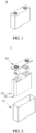
- FIG. 1 shows a prismatic lithium-ion secondary battery 5 as an example.
- the outer package may include a housing 51 and a cover plate 53.
- the housing 51 may include a bottom plate and a side plate connected to the bottom plate. The bottom plate and the side plate close in to form an accommodation cavity. An opening that communicates with the accommodation cavity is created on the housing 51.
- the cover plate 53 can fit and cover the opening to close the accommodation cavity.
- the positive electrode plate, the negative electrode plate, and the separator may be made into the electrode assembly 52 by winding or stacking.
- the electrode assembly 52 is packaged in the accommodation cavity.
- the electrolyte solution infiltrates in the electrode assembly 52.
- the number of electrode assemblies 52 contained in a lithium-ion secondary battery 5 may be one or more, and is adjustable as required.
- the lithium-ion secondary battery may be assembled to form a battery module.
- the battery module may contain a plurality of secondary batteries, and the specific number of secondary batteries in a battery module may be adjusted according to practical applications and capacity of the battery module.
- FIG. 3 shows a battery module 4 as an example.
- a plurality of lithium-ion secondary batteries 5 may be arranged sequentially along a length direction of the battery module 4.
- the secondary batteries may be arranged in any other manner.
- the plurality of secondary batteries 5 may be fixed by a fastener.
- the battery module 4 may further include a shell that provides an accommodation space.
- the plurality of secondary batteries 5 are accommodated in the accommodation space.
- the battery module may be assembled to form a battery pack.
- the number of the battery modules contained in a battery pack may be adjusted according to practical applications and the capacity of the battery pack.
- FIG. 4 and FIG. 5 show a battery pack 1 as an example.
- the battery pack 1 may include a battery box and a plurality of battery modules 4 disposed in the battery box.
- the battery box includes an upper box 2 and a lower box 3.
- the upper box 2 fits the lower box 3 to form a closed space for accommodating the battery modules 4.
- the plurality of battery modules 4 may be arranged in the battery box in any manner.
- the device includes at least one of the lithium-ion secondary battery, the battery module, or the battery pack according to this application.
- the lithium-ion secondary battery may be used as a power supply of the device, or used as an energy storage unit of the device.
- the device may be, but is not limited to, a mobile device (such as a mobile phone or a laptop computer), an electric vehicle (such as a battery electric vehicle, a hybrid electric vehicle, a plug-in hybrid electric vehicle, an electric bicycle, an electric scooter, an electric golf cart, or an electric truck), an electric train, a ship, a satellite system, or an energy storage system.
- the lithium-ion secondary battery, battery module, or battery pack may be selected for use in the device.
- the device may be a mobile phone, a tablet computer, a laptop computer, or the like.
- the device is generally required to be thin and light, and may use a lithium-ion secondary battery as a power supply.
- a first positive electrode material LiFePO 4 Dissolving a first positive electrode material LiFePO 4 , a second positive electrode material Li 2 Ni 0.498 Cu 0.498 Ti 0.002 O 2 , a binder polyvinylidene difluoride (PVDF), a conductive agent carbon black at a mass ratio of 92.4: 4.0: 2.1: 1.5 in an N-methyl-pyrrolidone (NMP) solvent, and vacuum-mixing the mixture thoroughly until the mixture becomes a homogeneous transparent system to obtain a positive electrode slurry. Subsequently, coating a positive current collector aluminum foil with the positive electrode slurry evenly, transferring the coated current collector into an oven to dry the slurry at 120 °C, and then performing cold pressing and slitting to obtain a positive electrode.
- the mass percent of the first positive electrode material LiFePO 4 is 92.4%
- the mass percent of the second positive electrode material Li 2 Ni 0.498 Cu 0.498 Ti 0.002 O 2 is 4.0%.
- CMC-Na sodium carboxymethyl cellulose
- SBR styrene-butadiene rubber
- EC ethylene carbonate
- EMC ethyl methyl carbonate
- DEC diethyl carbonate
- the lithium-ion secondary battery is prepared in the same way as in Embodiment 1 except that the type of the first positive electrode material, the type of the second positive electrode material, and the content of the vinylene carbonate in the electrolyte solution are changed according to Table 1.
- a characteristic diffraction peak is exhibited at 36° to 38°, a characteristic diffraction peak is exhibited at 42° to 44°, and a characteristic diffraction peak is exhibited at 62° to 64°.
- the characteristic diffraction peak is a characteristic peak of a rock-salt phase material. Therefore, it is confirmed that in the X-ray diffraction pattern of the second positive electrode material after first-cycle charging, a characteristic diffraction peak is exhibited at 36° to 38°, a characteristic diffraction peak is exhibited at 42° to 44°, and a characteristic diffraction peak is exhibited at 62° to 64°.
- Embodiment 5 Li 0.95 FePO 3.95 F 0.05 /Li 2 Ni 0.498 Cu 0.498 Ti 0.002 O 2 92.4 4.0 3 2265 97.0 171
- Embodiment 6 Li 1.05 FePO 3.95 N 0.05 /Li 2 Ni 0.498 Cu 0.498 Ti 0.002 O 2 92.4 4.0 3 2272 97.1 172
- Embodiment 7 LiFe 0.95 PV 0.0125 Cr 0.0125 O 4 / Li 2 Ni 0.498 Cu 0.498 Ti 0.002 O 2 92.4 4.0 3 2283 97.0 171
- Embodiment 8 LiFePO 4 /Li 2 Ni 0.446 Cu 0 .446 Ti 0.004 Mn 0.1 O 2 92.4 4.0 3 2289 97.1 173
- Embodiment 9 LiFePO 4 /Li 2 Ni 0.442 Cu 0 .442 Ti 0.008 Mn 0.05 Co 0.05 O 2 92.4 4.0 3 2298 97.3
- the lithium-ion secondary battery achieves a high energy density, good C-rate performance, and a long cycle life concurrently.
- the positive electrode material layer does not include the first positive electrode material or the second positive electrode material of this application, the energy density of the lithium-ion secondary battery is decreased, and the number of high-temperature cycles of the battery is reduced.
- the film resistance of the positive electrode plate is measured by the method to be described below.
- the compaction density and single-side areal density of the positive electrode plate are calculated by the method to be described below.
- Measuring the resistance of the positive electrode plate by using a Hioki BT3562 resistance tester Specifically, clamping the positive electrode plate between two conductive terminals (14 mm in diameter) of the internal resistance tester, and applying a pressure of 15 MPa to 27 MPa to fix the electrode plate, and measuring the resistance R of the positive electrode plate by sampling the resistance values at intervals of 5 s to 17 s.
- the positive electrode plate satisfy 0.5 ⁇ R ⁇ P/Q ⁇ 16
- the energy density, C-rate performance, and cycle life of the lithium-ion secondary battery can be further improved.
- the positive electrode plate further satisfy 1.5 ⁇ R ⁇ P/Q ⁇ 10
- the energy density, C-rate performance, and cycle life of the lithium-ion secondary battery can be even further improved.
Landscapes
- Chemical & Material Sciences (AREA)
- General Chemical & Material Sciences (AREA)
- Chemical Kinetics & Catalysis (AREA)
- Electrochemistry (AREA)
- Engineering & Computer Science (AREA)
- Inorganic Chemistry (AREA)
- Materials Engineering (AREA)
- Manufacturing & Machinery (AREA)
- Composite Materials (AREA)
- Organic Chemistry (AREA)
- Physics & Mathematics (AREA)
- Condensed Matter Physics & Semiconductors (AREA)
- General Physics & Mathematics (AREA)
- Crystallography & Structural Chemistry (AREA)
- Battery Electrode And Active Subsutance (AREA)
- Secondary Cells (AREA)
Abstract
Description
- This application relates to a lithium-ion secondary battery, a battery module, a battery pack, and an electrical device.
- During a first charge-discharge cycle of a lithium-ion secondary battery, a solid electrolyte interface (SEI) is formed on a surface of a negative electrode of the battery, thereby causing an irreversible loss of capacity, and in turn, reducing an energy density of the lithium-ion energy storage device. In a device that uses graphite as an negative electrode material, approximately 10% of an active lithium source is consumed in the first charge-discharge cycle. In a device that uses a high-specific-capacity negative electrode material such as an alloy (silicon or tin alloy or the like), an oxide (silicon oxide, tin oxide, or the like), or amorphous carbon, the consumption of the active lithium source is further increased. Therefore, finding an appropriate lithium supplementing method is of great significance to further increasing the energy density of the lithium-ion secondary battery.
- For this purpose, a method for supplementing lithium for the negative electrode by using lithium powder such as stabilized lithium metal powder (SLMP, stabilized lithium metal powder) is put forward in the industry. However, although this method can increase the energy density of the battery, the lithium metal powder is of very high reactivity and is prone to react with moisture in the air, thereby posing a severe safety hazard. In a production process, a nonaqueous organic solvent that does not react with lithium is required to be used, and the control on moisture is also extremely stringent, thereby increasing the difficulty of the process.
- In view of the great challenges encountered by the negative electrode lithium supplementation policy, a positive electrode lithium supplementation method is safer and easier to operate, and has drawn more and more attention from the industry. For example, Patent Document 1 discloses a positive electrode lithium-supplementing material based on a lithium-oxygen compound, a lithium source, and alkyl lithium. However, a decomposition potential of the lithium-containing compound in the material is relatively high, and oxygen and other by-products are generated in the decomposition process, thereby shortening the battery life.
- In addition, known lithium-supplementing materials include a Li2NiO2 lithium-supplementing material. However, a very high content of free lithium exists on the surface of such a material, and is very prone to cause gelation of a slurry during mixing of the slurry, thereby drastically impairing the processability. In addition, during the first charging cycle, a large amount of active lithium is intercalated into the negative electrode, thereby leading to a further decrease in the true potential of the negative electrode. Moreover, this makes reduction reactions of the solvent in an electrolyte solution occur continuously on the negative electrode, thereby resulting in a continuous increase in impedance, and in turn, impairing the cycle performance of the battery.
- Patent document 1:
CN104037418A - This application is developed in view of the above situation, and an objective of this application is to provide a lithium-ion secondary battery capable of achieving a balanced high level of energy density, cycle life, C-rate performance, and the like.
- To achieve the above objective, this application provides a lithium-ion secondary battery. The lithium-ion secondary battery includes a positive electrode plate, a negative electrode plate, a separator, and an electrolyte solution.
- The positive electrode plate includes a positive current collector and a positive electrode material layer disposed on at least one surface of the positive current collector.
- The positive electrode material layer includes a first positive electrode material represented by the following General Formula (1) and a second positive electrode material represented by the following General Formula (2).
- The electrolyte solution includes vinylene carbonate.
- A content of the vinylene carbonate based on a total mass of the electrolyte solution is greater than or equal to 0.1 wt% and less than or equal to 5 wt%.
Li1+xFeyMnzM1-y-zPO4-tAt (1)
- (In General Formula (1), M includes one or more of Ti, Zr, V, or Cr; A includes one or more of S, N, F, Cl, or Br; and x, y, z, and t satisfy: -0.1 ≤ x < 0.1, 0 < y ≤ 1, 0 ≤ z < 1, 0 < y + z ≤ 1, and 0 ≤ t < 0.2.)
Li2+rNi0.5-pCu0.5-qTivNp+q-vO2-sBs (2)
- (In General Formula (2), N includes one or more of Mn, Fe, Co, Al, V, Cr, or Nb; B includes one or more of S, N, F, Cl, or Br; and r, p, q, v, and s satisfy: -0.2 ≤ r ≤ 0.2, -0.5 < p < 0.5, -0.5 < q < 0.5, 0 < v < 0.01, 0 ≤ p + q - v < 0.2, and 0 ≤ s < 0.2)
- As used in the positive electrode plate, the positive electrode material layer includes both the first positive electrode material and the second positive electrode material. The second positive electrode material forms a solid solution that exhibits a lower phase transformation energy barrier, a higher purity, and a higher specific capacity than an existing Li2NiO2 lithium-supplementing material. The second positive electrode material coordinates with the first positive electrode material of an olivine structure to effectively improve the energy density, cycle life, and C-rate performance of the lithium-ion secondary battery. In addition, by adding a specified amount of vinylene carbonate additive into the electrolyte solution, the electrolyte solution can be synergistic with the first positive electrode material and the second positive electrode material of this application to form a more uniform and denser SEI film at the negative electrode after the first-cycle charging, thereby suppressing continuous loss of active lithium and further improving the cycle life of the lithium-ion secondary battery.
- In some embodiments, in General Formula (2), p, q, and v satisfy: -0.1 < p < 0.1, -0.1 < q < 0.1, and 0.002 ≤ v ≤ 0.008. By making p, q, and v satisfy the specified ranges, the content of free lithium on the surface of the material can be further reduced, and the problem of gelation of the positive electrode slurry can be greatly alleviated, thereby achieving a more balanced high level of energy density, cycle life, and C-rate performance.
- In some embodiments, the positive electrode plate satisfies the following Formula (3):

(In Formula (3), R represents a resistance of the positive electrode plate, in units of Ω; P represents a compaction density of the positive electrode plate, in units of g/cm3; and Q represents a single-side areal density of the positive electrode plate, in units of g/1540.25 mm2.) - By making the positive electrode plate satisfy Formula (3) above, the energy density, C-rate performance, and cycle life of the lithium-ion secondary battery can be further improved.
- In some embodiments, the positive electrode plate further satisfies the following Formula (4):

- By making the positive electrode plate further satisfy Formula (4) above, the energy density, C-rate performance, and cycle life of the lithium-ion secondary battery can be even further improved.
- In some embodiments, the resistance of the positive electrode plate satisfies: R ≤ 3 Ω, and optionally satisfies: R ≤ 1 Ω. By making the resistance of the positive electrode plate fall within the specified range, the cycle performance and C-rate performance of the lithium-ion secondary battery are improved.
- In some embodiments, the compaction density P of the positive electrode plate satisfies: 1.6 < P < 2.6 (in units of g/cm3). By making the compaction density P of the positive electrode plate fall within the specified range, the migration of electrons and ions in the positive electrode plate is facilitated, thereby improving the cycle performance of the lithium-ion secondary battery.
- In some embodiments, the single-side areal density Q of the positive electrode plate satisfies: 0.16 < Q < 0.45 (in units of g/1540.25 mm2). By making the single-side areal density Q of the positive electrode plate fall within the specified range, the cycle performance and C-rate performance of the lithium-ion secondary battery can be improved at the same time as ensuring a high level of charge capacity and discharge capacity.
- In some embodiments, a mass ratio between the first positive electrode material and the second positive electrode material is 5: 1 to 99: 1, and optionally 9: 1 to 99: 1. By making the mass ratio between the first positive electrode material and the second positive electrode material fall within the specified range, the first positive electrode material accounts for a larger proportion of the combination of the first positive electrode material and the second positive electrode material, and the positive electrode plate is of higher structural stability, thereby reducing capacity loss and impedance increase caused by structural disruption of the positive electrode material, and maintaining a high level of cycle stability and kinetic performance.
- In some embodiments, in the positive electrode material layer, a percentage by weight of the first positive electrode material is 80 wt% to 98 wt%, and optionally 85 wt% to 98 wt%. By making the weight percent of the first positive electrode material in the positive electrode material layer fall within the specified range, the positive electrode plate is of even higher structural stability, thereby further reducing capacity loss and impedance increase caused by structural disruption of the positive electrode material, and improving the cycle stability and kinetic performance.
- A crystal structure of the second positive electrode material belongs to an orthorhombic Immm space group.
- In some embodiments, in an X-ray diffraction pattern of the second positive electrode material after first-cycle charging, a characteristic diffraction peak A is exhibited at 36° to 38°, a characteristic diffraction peak B is exhibited at 42° to 44°, and a characteristic diffraction peak C is exhibited at 62° to 64°.
- A second aspect of this application provides a battery module. The battery module includes the secondary battery according to the first aspect of this application.
- A third aspect of this application provides a battery pack. The battery pack includes the battery module according to the second aspect of this application.
- A fourth aspect of this application provides a device. The device includes at least one of the secondary battery according to the first aspect of this application, the battery module according to the second aspect of this application, or the battery pack according to the third aspect of this application.
- The battery module, the battery pack, and the device of this application each include the secondary battery according to this application, and therefore, exhibit at least the same advantages as the secondary battery.
-
-
FIG. 1 is a schematic diagram of a secondary battery according to an embodiment of this application; -
FIG. 2 is an exploded view of the secondary battery shown inFIG. 1 according to an embodiment of this application; -
FIG. 3 is a schematic diagram of a battery module according to an embodiment of this application; -
FIG. 4 is a schematic diagram of a battery pack according to an embodiment of this application; -
FIG. 5 is an exploded view of the battery pack shown inFIG. 4 according to an embodiment of this application; and -
FIG. 6 is an X-ray diffraction pattern of a positive electrode plate of a lithium-ion secondary battery obtained in Embodiment 1 and tested after first-cycle charging. - To make the objectives, technical solutions, and advantages of this application clearer, the following describes some embodiments of this application in detail with reference to accompanying drawings. However, a person of ordinary skill in the art understands that such embodiments are just intended to expound rather than limit the technical solutions hereof. Any and all modifications, equivalent replacements, improvements, and the like made without departing from the essence and principles of this application still fall within the protection scope of this application.
- For brevity, some specific numerical ranges are disclosed herein. However, any lower limit may be combined with any upper limit to form an unspecified range, any lower limit may be combined with any other lower limit to form an unspecified range, and any upper limit may be combined with any other upper limit to form an unspecified range. In addition, although not explicitly stated, any point and any single numerical value between end points of a range are included in the range. In addition, each separately disclosed point or single numerical value may be used as a lower limit or upper limit to combine with any other point or other single numerical value or with any other lower or upper limit to form an unspecified range.
- It is hereby noted that in the description herein, unless otherwise specified, a range defined by a numerical value qualified by "at least" or "at most" includes this numerical value, and the word "more" in the phrase "one or more of" means at least two.
- The above summary of this application is not intended to describe every disclosed embodiment or every implementation of this application. The following description exemplifies illustrative embodiments in more detail. In several places throughout this application, guidance is provided through a series of embodiments. The embodiments may be used in various combinations. In each instance, an enumerated list serves merely as a representative list, but is not to be construed as an exclusive list.
- To solve the above problems in the prior art, after in-depth research the applicant hereof finds that: by compounding the existing Li2NiO2 lithium-supplementing material with Cu, Ti, and other optional metal elements, the second positive electrode material forms a solid solution that exhibits a lower phase transformation energy barrier, a higher purity, and a higher specific capacity than the existing Li2NiO2 lithium-supplementing material. The second positive electrode material coordinates with the first positive electrode material of an olivine structure to make following improvements: on the one hand, the loss of active lithium caused by the formation of the SEI film is compensated for effectively during file-cycle charging of the battery by virtue of the second positive electrode material characterized by a high first-charge specific capacity and a low initial Coulombic efficiency. During the first discharge, sufficient lithium ions are intercalated back into the first positive electrode material, thereby increasing the energy density of the battery effectively. On the other hand, the first positive electrode material of an olivine structure in this application is structurally stable, little changes in volume during charging and discharging, and is excellent in cycle stability. Further, the applicant hereof finds that, by adding a specified amount of vinylene carbonate into the electrolyte solution, the electrolyte solution can be synergistic with the positive electrode plate containing the first positive electrode material and the second positive electrode material, so as to form a more uniform and denser SEI film at the negative electrode after the first-cycle charging, thereby suppressing continuous loss of active lithium and further improving the cycle life of the lithium-ion secondary battery. Therefore, the lithium-ion secondary battery according to this embodiment achieves a high energy density, good C-rate performance, and a long cycle life.
- Specifically, this application relates to a lithium-ion secondary battery. The lithium-ion secondary battery includes a positive electrode plate, a negative electrode plate, a separator, and an electrolyte solution. The positive electrode plate includes a positive current collector and a positive electrode material layer disposed on at least one surface of the positive current collector.
- The positive electrode material layer includes a first positive electrode material represented by the following General Formula (1) and a second positive electrode material represented by the following General Formula (2):
The electrolyte solution includes vinylene carbonate. - A content of the vinylene carbonate based on a total mass of the electrolyte solution is greater than or equal to 0.1 wt% and less than or equal to 5 wt%.
Li1+xFeyMnzM1-y-zPO4-tAt (1)
- (In General Formula (1), M includes one or more of Ti, Zr, V, or Cr; A includes one or more of S, N, F, Cl, or Br; and x, y, z, and t satisfy: -0.1 ≤ x < 0.1, 0 < y ≤ 1, 0 ≤ z < 1, 0 < y + z ≤ 1, and 0 ≤ t < 0.2.)
Li2+rNi0.5-pCu0.5-qTivNp+q-vO2-sBs (2)
- (In General Formula (2), N includes one or more of Mn, Fe, Co, Al, V, Cr, or Nb; B includes one or more of S, N, F, Cl, or Br; and r, p, q, v, and s satisfy: -0.2 ≤ r ≤ 0.2, -0.5 < p < 0.5, -0.5 < q < 0.5, 0 < v < 0.01, 0 ≤ p + q - v < 0.2, and 0 ≤ s < 0.2)
- A lithium-ion battery, a battery module, a battery pack, and an electrical device of this application are described in detail below with due reference to drawings.
- A lithium-ion secondary battery is a battery that is reusable through activation of an active material in the lithium-ion battery by charging the battery that has been discharged. Generally, a lithium-ion secondary battery includes a positive electrode plate, a negative electrode plate, a separator, and an electrolyte solution. In a charge-and-discharge cycle of the battery, active ions are shuttled between the positive electrode plate and the negative electrode plate by intercalation and deintercalation. Disposed between the positive electrode plate and the negative electrode plate, the separator can isolate electrons to prevent an internal short circuit while allowing active ions to pass through the separator and move between the positive electrode and the negative electrode. The separator serves a separation function. The electrolyte solution serves to conduct ions between the positive electrode plate and the negative electrode plate.
- A positive electrode plate includes a positive current collector and a positive electrode material layer disposed on at least one surface of the positive current collector. As an example, the positive current collector includes two surfaces opposite to each other in a thickness direction of the current collector. The positive electrode material layer is disposed on any one or both of the two opposite surfaces of the positive current collector.
- The positive electrode material layer includes a first positive electrode material represented by the following General Formula (1) and a second positive electrode material represented by the following General Formula (2):
Li1+xFeyMnzM1-y-zPO4-tAt (1)
- (In General Formula (1), M includes one or more of Ti, Zr, V, or Cr; A includes one or more of S, N, F, Cl, or Br; and x, y, z, and t satisfy: -0.1 ≤ x < 0.1, 0 < y ≤ 1, 0 ≤ z < 1, 0 < y + z ≤ 1, and 0 ≤ t < 0.2.)
Li2+rNi0.5-pCu0.5-qTivNp+q-vO2-sBs (2)
- (In General Formula (2), N includes one or more of Mn, Fe, Co, Al, V, Cr, or Nb; B includes one or more of S, N, F, Cl, or Br; and r, p, q, v, and s satisfy: -0.2 ≤ r ≤ 0.2, -0.5 < p < 0.5, -0.5 < q < 0.5, 0 < v < 0.01, 0 ≤ p + q - v < 0.2, and 0 ≤ s < 0.2)
- By letting the positive electrode material layer include both the first positive electrode material and the second positive electrode material, the lithium-ion secondary battery achieves a high energy density, good C-rate performance, and a long cycle life.
- In general formula (1), x satisfies -0.1 ≤ x < 0.1. To further reduce the volume change during charging and discharging and further improve the cycle stability of the battery, x preferably falls within: -0.1 ≤ x ≤ 0.05, and more preferably falls within: -0.05 ≤ x ≤ 0. In addition, y satisfies: 0 < y ≤ 1. To further improve the cycle stability of the battery, y preferably falls within: 0.5 ≤ y ≤ 1, and more preferably falls within: 0.5 ≤ y ≤ 0.95. Moreover, z satisfies: 0 ≤ z < 1. To improve the cycle stability of the battery, z preferably falls within: 0 ≤ z ≤ 0.5, and more preferably falls within: 0.025 ≤ z ≤ 0.45.
- In General Formula (1), M is one or more selected from Ti, Zr, V, or Cr. To be synergistic with the second positive electrode material and increase the energy density and cycle life of the lithium-ion secondary battery, M is preferably one or more selected from Ti, Zr, or V, and more preferably one or more selected from Ti or Zr. In addition, A includes one or more of S, N, F, Cl, or Br. To maintain excellent overall performance, A is preferably one or more selected from F, Cl, or Br, and more preferably is F. Moreover, t satisfies: 0 ≤ t < 0.2. To maintain excellent overall performance, t preferably falls within: 0 ≤ t ≤ 0.05.
- In General Formula (1), y+z satisfies: 0 < y+z ≤ 1. To be synergistic with the second positive electrode material and increase the energy density and cycle life of the lithium-ion secondary battery, y+z preferably falls within: 0.95 ≤ y+z ≤ 1.
- In General Formula (2), r satisfies: -0.2 ≤ r ≤ 0.2. To effectively compensate for the loss of active lithium caused by the formation of the SEI film and further increase the energy density of the battery, r preferably falls within: -0.05 ≤ r ≤ 0.2, and more preferably falls within: 0 ≤ r ≤ 0.2. In addition, p satisfies: -0.5 < p < 0.5. To further increase the energy density of the battery, p preferably falls within: -0.1 < p < 0.1, more preferably falls within: -0.046 ≤ p ≤ 0.058, and even more preferably falls within: 0.002 ≤ p ≤ 0.054. Moreover, q satisfies: -0.5 < q < 0.5. To effectively increase the energy density and cycle life of the battery, q preferably falls within: -0.1 < q < 0.1, more preferably falls within: -0.046 ≤ q ≤ 0.058, and even more preferably falls within: 0.002 ≤ q ≤ 0.054. Further, v satisfies: 0 < v < 0.01. To more effectively reduce the content of free lithium on the surface of the material, and more effectively alleviate the problem of gelation of the positive electrode slurry, and effectively increase the energy density of the battery, v preferably falls within: 0.002 ≤ v ≤ 0.008, and more preferably falls within: 0.004 ≤ v ≤ 0.008. Further, s satisfies: 0 ≤ s < 0.2. To improve the cycle performance and energy density of the battery, s preferably falls within: 0 ≤ s ≤ 0.1, and more preferably falls within: 0 ≤ s ≤ 0.05.
- In General Formula (2), N includes one or more of Mn, Fe, Co, Al, V, Cr, or Nb. To improve the C-rate performance and the cycle performance of the battery, N is preferably one or more selected from Mn, Fe, Co, or Cr, and more preferably one or more selected from Mn or Co. In addition, B includes one or more of S, N, F, Cl, or Br. To maintain excellent overall performance, B is preferably one or more selected from F, Cl, or Br, and more preferably is F.
- In General Formula (2), p+q-v satisfies: 0 ≤ p + q - v < 0.2. To improve the C-rate performance and cycle performance of the battery, p+q-v preferably satisfies: 0 ≤ p+q-v ≤ 0.1.
- In some embodiments, the positive electrode plate satisfies the following Formula (3):

(In Formula (3), R represents a resistance of the positive electrode plate, in units of Ω; P represents a compaction density of the positive electrode plate, in units of g/cm3; and Q represents a single-side areal density of the positive electrode plate, in units of g/1540.25 mm2.) - By making the positive electrode plate satisfy Formula (3) above, the energy density, C-rate performance, and cycle life of the lithium-ion secondary battery can be further improved.
- In some embodiments, preferably, the positive electrode plate further satisfies the following Formula (4):

- It is hereby noted that in this application, the calculation of R-P/Q involves only numerical calculation. For example, if the resistance R of the positive electrode is 0.5 Ω, the compaction density P is 2.2 g/cm3, and the single-side areal density Q of the positive electrode is 0.3 g/1540.25 mm2, then R·P/Q = 3.7.
- In some embodiments, the resistance of the positive electrode plate satisfies: R ≤ 3 Ω, and preferably satisfies: R ≤ 1 Ω. By making the resistance of the positive electrode plate fall within the specified range, the cycle performance and C-rate performance of the lithium-ion secondary battery are prevented from being deteriorated by an excessive resistance of the positive electrode plate, thereby improving the cycle performance and C-rate performance of the lithium-ion secondary battery. In this application, the resistance R of the positive electrode plate is a value measured by using a direct-current two-probe method. The contact area between the probe and the positive electrode plate is 49 π mm2. As an example, the upper and lower sides of the positive electrode plate are clamped between two conductive terminals (with a diameter of 14 mm) of an electrode plate resistance tester (Hioki BT23562 internal resistance tester manufactured by Hioki E.E. Corporation), and a pressure of 15 MPa to 27 MPa is applied to hold the electrode plate in place, so that the resistance of the positive electrode plate is measured by using the electrode plate resistance tester.
- In some embodiments, the compaction density P of the positive electrode plate satisfies: 1.6 < P < 2.6 (in units of g/cm3). By making the compaction density P of the positive electrode plate fall within the specified range, the cycle performance and C-rate performance of the battery are prevented from being deteriorated, thereby facilitating the migration of electrons and ions in the positive electrode plate, and improving the cycle performance of the lithium-ion secondary battery. In this application, the compaction density P of the positive electrode may be calculated by a formula P = m/v, where m is the mass of the positive electrode material layer in units of g, and v is the volume of the positive electrode material layer in units of cm3. The volume v of the positive electrode material layer may be a product of the area Ar of the positive electrode material layer and the thickness of the positive electrode material layer.
- In some embodiments, the single-side areal density Q of the positive electrode plate satisfies: 0.16 < Q < 0.45 (in units of g/1540.25 mm2). By making the single-side areal density Q of the positive electrode plate fall within the specified range, an excessive single-side areal density of the positive electrode plate is avoided so as not to reduce the cycle life of the battery, impair the C-rate performance of the battery, or reduce the discharge capacity of the battery at a high C-rate; and a deficient single-side areal density of the positive electrode plate is avoided so as not to increase the lengths of the current collector and the separator or increase the internal resistance of the battery while achieving the same capacity of the battery, thereby improving the cycle performance and C-rate performance of the lithium-ion secondary battery while ensuring a high level of charge capacity and discharge capacity. In this application, the single-side areal density Q of the positive electrode plate may be calculated by a formula Q = 1540.25 m/Ar, where m is the mass of the positive electrode material layer, in units of g, and Ar is the area of the positive active material layer, in units of mm2.
- In some embodiments, a mass ratio between the first positive electrode material and the second positive electrode material is 5: 1 to 99: 1, preferably 9: 1 to 99: 1, and more preferably 10: 1 to 48: 1. By making the mass ratio between the first positive electrode material and the second positive electrode material fall within the specified range, the first positive electrode material accounts for a larger proportion of the combination of the first positive electrode material and the second positive electrode material, and the positive electrode plate is of higher structural stability, thereby reducing capacity loss and impedance increase caused by structural disruption of the positive electrode material, and maintaining a high level of cycle stability and kinetic performance.
- In some embodiments, in the positive electrode material layer, a percentage by weight of the first positive electrode material is 80 wt% to 98 wt%, and preferably 85 wt% to 98 wt%. By making the weight percent of the first positive electrode material in the positive electrode material layer fall within the specified range, the positive electrode plate is of even higher structural stability, thereby further reducing capacity loss and impedance increase caused by structural disruption of the positive electrode material, and improving the cycle stability and kinetic performance.
- In some embodiments, the crystal structure of the second positive electrode material belongs to an orthorhombic Immm space group. In some embodiments, in an X-ray diffraction pattern of the second positive electrode material after first-cycle charging, a characteristic diffraction peak A is exhibited at 36° to 38°, a characteristic diffraction peak B is exhibited at 42° to 44°, and a characteristic diffraction peak C is exhibited at 62° to 64°.
- To the extent that the effect of this application is not impaired, the positive electrode material layer of this application may include other positive electrode materials such as lithium transition metal oxide in addition to the first positive electrode material and the second positive electrode material.
- The positive electrode material layer of this application optionally includes a binder and a conductive agent. The types of the conductive agent and binder are not particularly limited herein, and may be selected according to actual needs.
- As an example, the binder may include one or more of styrene-butadiene rubber (SBR), water-based acrylic resin (water-based acrylic resin), carboxymethyl cellulose (CMC), polyvinylidene difluoride (PVDF), polytetrafluoroethylene (PTFE), polyvinyl butyral (PVB), poly(ethylene-co-vinyl acetate) (EVA), or polyvinyl alcohol (PVA). The conductive agent may include one or more of graphite, superconductive carbon, acetylene black, carbon black, Ketjen black, carbon dots, carbon nanotubes, graphene, or carbon nanofibers.
- In some embodiments, the mass percent of the conductive agent in the positive electrode material layer is 0.5 wt% or above. By setting the mass percent of the conductive agent to fall within the above range, a relatively low resistance of the positive electrode plate can be achieved.
- In some embodiments, the mass percent of the binder in the positive electrode material layer is 2.5 wt% or below. By setting the mass percent of the binder to fall within the above range, a relatively low resistance of the positive electrode plate can be achieved.
- In the lithium-ion secondary battery of this application, the positive current collector may be a metal foil, a porous metal sheet, or a composite current collector. For example, the metal foil or porous metal sheet may be a foil or a porous sheet of metals such as aluminum, copper, nickel, titanium, silver, or an alloy thereof, and preferably an aluminum foil. The composite current collector may include a polymer material substrate and a metal layer formed on at least one surface of the polymer material substrate. The composite current collector may be formed by overlaying the polymer material substrate with a metal material (for example, aluminum, aluminum alloy, nickel, nickel alloy, titanium, titanium alloy, silver, or silver alloy). The polymer material substrate may be, for example, polypropylene (PP), polyethylene terephthalate (PET), polybutylene terephthalate (PBT), polystyrene (PS), or polyethylene (PE). The thickness of the positive current collector is 5 µm to 20 µm, and preferably, 6 µm to 18 µm, and more preferably, 8 µm to 16 µm.
- The positive electrode plate of this application may be prepared by a conventional method in this field. Specifically, the positive electrode plate may be prepared by the following method: dispersing the constituents of the positive electrode plate such as the first positive electrode material, the second positive electrode material, an optional conductive agent, an optional binder, and any other constituents into a solvent (such as N-methyl-pyrrolidone) to form a positive electrode slurry; coating a positive current collector with the positive electrode slurry, and performing steps such as oven-drying and cold pressing to obtain a positive electrode plate. Alternatively, the positive electrode plate may be manufactured by the following method: tape-casting a positive electrode slurry, which is prepared for forming a positive electrode material layer, onto a separate carrier, and then pressing a film, which is stripped off from the carrier, onto the positive current collector. In addition, in the above embodiment, the positive electrode slurry is prepared by directly mixing the first positive electrode material and the second positive electrode material. However, the slurry preparation method is not limited to this, but may be: blending the second positive electrode material separately to produce a slurry, and applying the slurry onto the upper or lower layer of the first positive electrode material.
- In the lithium-ion secondary battery, the negative electrode plate typically includes a negative current collector and a negative electrode material layer disposed on at least one surface of the negative current collector. For example, the negative current collector includes two surfaces opposite to each other in a thickness direction of the current collector. The negative electrode material layer is disposed on either or both of the two opposite surfaces of the negative current collector.
- In the lithium-ion secondary battery of this application, the negative current collector may be a metal foil, a porous metal sheet, a composite current collector, or made of other materials. For example, the metal foil or porous metal sheet may be a foil or a porous sheet of metals such as copper, nickel, titanium, iron, or an alloy thereof, and preferably a copper foil. The composite current collector may include a polymer material substrate and a metal layer formed on at least one surface of the polymer material substrate. The composite current collector may be formed by overlaying the polymer material substrate with a metal material (for example, copper, copper alloy, nickel, nickel alloy, titanium, titanium alloy, silver, or silver alloy). The polymer material substrate may be, for example, polypropylene (PP), polyethylene terephthalate (PET), polybutylene terephthalate (PBT), polystyrene (PS), or polyethylene (PE).
- In the lithium-ion secondary battery of this application, the negative electrode material layer typically includes a negative electrode material, and optionally, a conductive agent, a binder, and a thickener.
- The negative electrode material may be a negative electrode material commonly used for preparing a negative electrode of a lithium-ion secondary battery in this field. For example, the negative electrode material may be one or more of natural graphite, artificial graphite, mesocarbon microbead (MCMB), hard carbon, soft carbon, silicon, a silicon-carbon composite, SiO, a Li-Sn alloy, a Li-Sn-O alloy, Sn, SnO, SnO2, spinel-structured lithium titanium oxide Li4Ti5O12, a Li-Al alloy, or metallic lithium.
- As an example, the conductive agent may include one or more of graphite, superconductive carbon, acetylene black, carbon black, Ketjen black, carbon dots, carbon nanotubes, graphene, or carbon nanofibers.
- As an example, the binder may include one or more of styrene-butadiene rubber (SBR), polyvinylidene difluoride (PVDF), polytetrafluoroethylene (PTFE), polyvinyl butyral (PVB), water-based acrylic resin (water-based acrylic resin), or carboxymethyl cellulose (CMC).
- As an example, the thickener may be carboxymethyl cellulose (CMC) or the like.
- This application is not limited to such materials. This application may use other materials in addition to the materials that can be used as a negative electrode material, a conductive agent, a binder, and a thickener of a lithium-ion secondary battery.
- The negative electrode plate of this application may be prepared by a conventional method in this field. Specifically, a method for preparing the negative electrode plate includes: dispersing the negative electrode material and optionally the conductive agent, binder, and thickener in a solvent to form a homogeneous negative electrode slurry, coating a negative current collector with the negative electrode slurry, and performing steps such as oven-drying and cold pressing to obtain a negative electrode. The solvent may be N-methyl-pyrrolidone (NMP), deionized water, or the like.
- The electrolyte solution of this application includes an organic solvent, an electrolyte lithium salt, and an additive. The types of the organic solvent and the electrolyte lithium salt are not particularly limited herein, and may be selected according to actual needs.
- As an example, the solvent may be one or more, and preferably at least two, selected from ethylene carbonate (EC), propylene carbonate (PC), ethyl methyl carbonate (EMC), diethyl carbonate (DEC), dimethyl carbonate (DMC), dipropyl carbonate (DPC), methyl propyl carbonate (MPC), ethylene propyl carbonate (EPC), butylene carbonate (BC), fluoroethylene carbonate (FEC), methyl formate (MF), methyl acetate (MA), ethyl acetate (EA), propyl acetate (PA), methyl propionate (MP), ethyl propionate (EP), propyl propionate (PP), methyl butyrate (MB), ethyl butyrate (EB), 1,4-butyrolactone (GBL), sulfolane (SF), methyl sulfonyl methane (MSM), ethyl methyl sulfone (EMS), or (ethylsulfonyl)ethane (ESE).
- As an example, the electrolyte lithium salt may be one or more selected from lithium hexafluorophosphate (LiPF6), lithium tetrafluoroborate (LiBF4), lithium perchlorate (LiClO4), lithium hexafluoroarsenate (LiAsF6), lithium bisfluorosulfonimide (LiFSI), lithium bistrifluoromethanesulfonimide (LiTFSI), lithium trifluoromethanesulfonate (LiTFS), lithium difluoro(oxalato) borate (LiDFOB), lithium bis(oxalato)borate (LiBOB), lithium difluorophosphate (LiPO2F2), lithium difluoro(bisoxalato)phosphate (LiDFOP), or lithium tetrafluoro(oxalato)phosphate (LiTFOP).
- The electrolyte solution of this application includes vinylene carbonate (VC) as an additive. A content of the vinylene carbonate based on a total mass of the electrolyte solution is greater than or equal to 0.1 wt% and less than or equal to 5 wt%. By adding a specified amount of vinylene carbonate as an additive into the electrolyte solution, the electrolyte solution can be synergistic with the positive electrode plate containing the first positive electrode material and the second positive electrode material, so as to form a more uniform and denser SEI film at the negative electrode after the first-cycle charging, thereby suppressing continuous loss of active lithium and further improving the cycle life of the lithium-ion secondary battery.
- The electrolyte solution further optionally includes other additives. Without being limited herein, the types of other additives may be any additive suitable for use in a lithium-ion secondary battery and may be selected according to actual needs. As an example, the additives may include one or more of vinyl ethylene carbonate (VEC), succinonitrile (SN), adiponitrile (AND), 1,3-propene sultone (PST), sulfonate cyclic quaternary ammonium salt, tris(trimethylsilane)phosphate (TMSP), or tris(trimethylsilane)borate (TMSB).
- The electrolyte solution may be prepared by a conventional method in this field. Specifically, the electrolyte solution may be obtained by mixing well an organic solvent, an electrolyte lithium salt, vinylene carbonate, and other optional additives. Specific order of adding the materials is not particularly limited. For example, the electrolyte solution may be obtained by adding an electrolyte lithium salt, vinylene carbonate, and other optional additives into an organic solvent and mixing the materials well. As an example, the electrolyte lithium salt is added into the organic solvent first, and then the vinylene carbonate and other optional additives are separately or simultaneously added into the organic solvent.
- The type of the separator is not particularly limited herein, and may be any well-known porous separator that is stable both electrochemically and chemically for use in a lithium-ion secondary battery. For example, the separator may be a glass fiber film, non-woven fabric film, polyethylene film, polypropylene film, polyvinylidene difluoride film, or a multilayer composite film that contains one or at least two thereof, or any combination thereof.
- In some embodiments, a method for preparing the lithium-ion secondary battery is: stacking the positive electrode plate, the separator, and the negative electrode plate in sequence to obtain an electrode assembly in which the separator is located between the positive electrode plate and the negative electrode plate to serve a separation function; and then placing the electrode assembly into an outer package, injecting an electrolyte solution, and sealing the package to obtain a lithium-ion secondary battery. The electrode assembly may be obtained by, instead of the stacking process, a winding process in which the positive electrode plate, the separator, and the negative electrode plate are wound.
- In some embodiments, the outer package of the lithium-ion secondary battery may be a hard shell such as a hard plastic shell, an aluminum shell, a steel shell, or the like. Alternatively, the outer package of the lithium-ion secondary battery may be a soft package such as a pouch-type soft package. The material of the soft package may be plastic such as one or more of polypropylene (PP), polybutylene terephthalate (PBT), or polybutylene succinate (PBS).
- The shape of the lithium-ion secondary battery is not particularly limited in this application, and may be cylindrical, prismatic or any other shape.
FIG. 1 shows a prismatic lithium-ionsecondary battery 5 as an example. - In some embodiments, referring to
FIG. 2 , the outer package may include ahousing 51 and acover plate 53. Thehousing 51 may include a bottom plate and a side plate connected to the bottom plate. The bottom plate and the side plate close in to form an accommodation cavity. An opening that communicates with the accommodation cavity is created on thehousing 51. Thecover plate 53 can fit and cover the opening to close the accommodation cavity. The positive electrode plate, the negative electrode plate, and the separator may be made into theelectrode assembly 52 by winding or stacking. Theelectrode assembly 52 is packaged in the accommodation cavity. The electrolyte solution infiltrates in theelectrode assembly 52. The number ofelectrode assemblies 52 contained in a lithium-ionsecondary battery 5 may be one or more, and is adjustable as required. - In some embodiments, the lithium-ion secondary battery may be assembled to form a battery module. The battery module may contain a plurality of secondary batteries, and the specific number of secondary batteries in a battery module may be adjusted according to practical applications and capacity of the battery module.
-
FIG. 3 shows abattery module 4 as an example. Referring toFIG. 3 , in thebattery module 4, a plurality of lithium-ionsecondary batteries 5 may be arranged sequentially along a length direction of thebattery module 4. Alternatively, the secondary batteries may be arranged in any other manner. Further, the plurality ofsecondary batteries 5 may be fixed by a fastener. - Optionally, the
battery module 4 may further include a shell that provides an accommodation space. The plurality ofsecondary batteries 5 are accommodated in the accommodation space. - In some embodiments, the battery module may be assembled to form a battery pack. The number of the battery modules contained in a battery pack may be adjusted according to practical applications and the capacity of the battery pack.
-
FIG. 4 and FIG. 5 show a battery pack 1 as an example. Referring toFIG. 4 and FIG. 5 , the battery pack 1 may include a battery box and a plurality ofbattery modules 4 disposed in the battery box. The battery box includes anupper box 2 and alower box 3. Theupper box 2 fits thelower box 3 to form a closed space for accommodating thebattery modules 4. The plurality ofbattery modules 4 may be arranged in the battery box in any manner. - Another aspect of this application provides a device. The device includes at least one of the lithium-ion secondary battery, the battery module, or the battery pack according to this application. The lithium-ion secondary battery may be used as a power supply of the device, or used as an energy storage unit of the device. The device may be, but is not limited to, a mobile device (such as a mobile phone or a laptop computer), an electric vehicle (such as a battery electric vehicle, a hybrid electric vehicle, a plug-in hybrid electric vehicle, an electric bicycle, an electric scooter, an electric golf cart, or an electric truck), an electric train, a ship, a satellite system, or an energy storage system.
- Depending on the use requirements of the device, the lithium-ion secondary battery, battery module, or battery pack may be selected for use in the device.
- As an example, the device may be a mobile phone, a tablet computer, a laptop computer, or the like. The device is generally required to be thin and light, and may use a lithium-ion secondary battery as a power supply.
- The following describes some embodiments of this application. The embodiments described below are illustrative, and are merely intended to construe this application but not to limit this application. Unless techniques or conditions are otherwise expressly specified in an embodiment hereof, the techniques or conditions described in the literature in this field or in an instruction manual of the product are applicable in the embodiment. A reagent or instrument used herein without specifying a manufacturer is a conventional product that is commercially available in the market.
- Dissolving a first positive electrode material LiFePO4, a second positive electrode material Li2Ni0.498Cu0.498Ti0.002O2, a binder polyvinylidene difluoride (PVDF), a conductive agent carbon black at a mass ratio of 92.4: 4.0: 2.1: 1.5 in an N-methyl-pyrrolidone (NMP) solvent, and vacuum-mixing the mixture thoroughly until the mixture becomes a homogeneous transparent system to obtain a positive electrode slurry. Subsequently, coating a positive current collector aluminum foil with the positive electrode slurry evenly, transferring the coated current collector into an oven to dry the slurry at 120 °C, and then performing cold pressing and slitting to obtain a positive electrode. In the positive electrode material layer, the mass percent of the first positive electrode material LiFePO4 is 92.4%, and the mass percent of the second positive electrode material Li2Ni0.498Cu0.498Ti0.002O2 is 4.0%.
- Dissolving artificial graphite as a negative electrode material, sodium carboxymethyl cellulose (CMC-Na) as a thickener, styrene-butadiene rubber (SBR), and carbon black as a conductive agent at a mass ratio of 95.7: 1.0: 1.8: 1.5 in deionized water, and mixing the mixture well with a vacuum mixer to obtain a negative electrode slurry. Subsequently, coating a negative current collector copper foil with the negative electrode slurry evenly, transferring the current collector into an oven to dry the slurry at 120 °C, and then performing cold pressing and slitting to obtain a negative electrode plate.
- Mixing ethylene carbonate (EC), ethyl methyl carbonate (EMC), and diethyl carbonate (DEC) at a volume ratio of 1: 1: 1, and stirring the mixture well to obtain an organic solvent. Dissolving 1 mol/L LiPF6 in the organic solvent, and then adding 3 wt% vinylene carbonate (VC), and stirring well to obtain an electrolyte solution, where the mass percent of the vinylene carbonate is a percentage by weight based on the total mass of the electrolyte solution.
- Stacking the positive electrode plate, the separator, and the negative electrode plate in sequence in such a way that the separator is located between the positive electrode plate and the negative electrode plate to serve a separation function, and then winding the stacked structure to form an electrode assembly; welding tabs to the electrode assembly, placing the electrode assembly into a shell, injecting the electrolyte solution and sealing the opening, and then performing steps such as static standing, chemical formation, and shaping to obtain a lithium-ion secondary battery.
- The lithium-ion secondary battery is prepared in the same way as in Embodiment 1 except that the type of the first positive electrode material, the type of the second positive electrode material, and the content of the vinylene carbonate in the electrolyte solution are changed according to Table 1.
- A performance test is performed by the following methods on the lithium-ion secondary batteries prepared in the above embodiments and comparative embodiments, and the test results obtained are shown in Table 1.
- Charging a lithium-ion secondary battery at a constant current of 1 C rate at 60 °C until the voltage reaches 4.2 V, and then charging the battery at a constant voltage until the current is less than or equal to 0.05 C, and then discharging the battery at a constant current of 1 C until the voltage drops to 2.5 V, thereby completing one charge-discharge cycle. Recording the first-cycle discharge capacity of the lithium-ion secondary battery. Repeating the charge-discharge cycle for the lithium-ion secondary battery according to the foregoing steps, and recording the discharge capacity at the end of each cycle until the discharge capacity of the lithium-ion secondary battery fades to 80% of the first-cycle discharge capacity. Recording the number of charge-discharge cycles.
- Charging a lithium-ion secondary battery at a constant current rate of 0.5 C at 25 °C until the voltage reaches 4.2 V, and then charging the battery at a constant voltage until the current is less than or equal to 0.05 C, and then discharging the battery at a constant current rate of 0.5 C until the voltage reaches 2.5 V, and recording the 0.5 C-rate discharge capacity.
- Charging the lithium-ion secondary battery at a constant current rate of 0.5 C at 25 °C until the voltage reaches 4.2 V, and then charging the battery at a constant voltage until the current is less than or equal to 0.05 C, and then discharging the battery at a constant current rate of 2 C until the voltage reaches 2.5 V, and recording the 2 C-rate discharge capacity.
- Subsequently, calculating, by using the following formula, the 2 C-rate discharge capacity retention rate (%) of the lithium-ion secondary battery to characterize the C-rate performance (%) of the battery.
2 C-rate discharge capacity retention rate of the lithium-ion secondary battery (%) = 2 C-rate discharge capacity / 0.5 C-rate discharge capacity × 100%. - Charging a lithium-ion secondary battery at a constant current rate of 0.2 C at 25 °C until the voltage reaches 4.2 V, and then charging the battery at a constant voltage until the current is less than or equal to 0.05 C. Subsequently, leaving the battery to stand for 30 minutes, and then discharging the battery at a constant current rate of 0.2 C until the voltage reaches 2.5 V, and recording the 0.2 C-rate discharge capacity of the secondary lithium-ion battery as D0 (Ah), and recording the discharge plateau as V0 (V). Weighing the lithium-ion battery and recording the weight as m0 (kg). Subsequently, calculating the energy density of the lithium-ion secondary battery (unit: Wh/Kg) by using the following formula:

- Charging the lithium-ion secondary battery, which is prepared in Embodiment 1, at a constant current rate of 1 C at 25 °C until the voltage reaches 4.2 V, and then charging the battery at a constant voltage until the current is less than or equal to 0.05 C. Disassembling the lithium-ion secondary battery charged for a first cycle, and taking out the positive electrode plate. Testing the positive electrode plate by using an X-ray diffractometer, and observing the resultant XRD pattern of the positive electrode plate after the first-cycle charging, as shown in
FIG. 6 . - As can be seen from
FIG. 6 , in the X-ray diffraction pattern after first-cycle charging, a characteristic diffraction peak is exhibited at 36° to 38°, a characteristic diffraction peak is exhibited at 42° to 44°, and a characteristic diffraction peak is exhibited at 62° to 64°. The characteristic diffraction peak is a characteristic peak of a rock-salt phase material. Therefore, it is confirmed that in the X-ray diffraction pattern of the second positive electrode material after first-cycle charging, a characteristic diffraction peak is exhibited at 36° to 38°, a characteristic diffraction peak is exhibited at 42° to 44°, and a characteristic diffraction peak is exhibited at 62° to 64°.Table 1 Serial number Positive electrode material Content of first positive electrode material (wt%) Content of second positive electrode material (wt%) Content of VC in electrolyte solution (wt%) Number of high-temperature cycles C-rate performance (%) Energy density (Wh/kg) Comparative Embodiment 1 LiFePO4 96.4 / 3 1450 98.4 162 Comparative Embodiment 2 Li2NiO2 / 96.4 3 1 74.6 140 Comparative Embodiment 3 Li2CuO2 / 96.4 3 1 75.4 138 Comparative Embodiment 4 LiFePO4/Li2NiO2 92.4 4.0 3 2045 96.4 168 Comparative Embodiment 5 LiFePO4/Li2Ni0.5Cu0.5 O2 92.4 4.0 3 2089 96.5 169 Comparative Embodiment 6 LiFePO4/Li2Ni0.498Cu0 .498Ti0.002O2 92.4 4.0 0 1035 98.1 171 Comparative Embodiment 7 LiFePO4/Li2Ni0.498Cu0 .498Ti0.002O2 92.4 4.0 7 2001 96.7 171 Embodiment 1 LiFePO4/Li2Ni0.498Cu0 .498Ti0.002O2 92.4 4.0 3 2331 97.1 172 Embodiment 2 LiFe0.5Mn0.5PO4/Li2N i0.498Cu0.498Ti0.002O2 92.4 4.0 3 2219 96.9 189 Embodiment 3 Li0.9Fe0.5Mn0.45Ti0.05P O4/Li2Ni0.498Cu0.498Ti0 .002O2 92.4 4.0 3 2267 96.9 190 Embodiment 4 Li0.9Fe0.5Mn0.45Ti0.04Z r0.01PO4[Li2Ni0.498Cu0. 498Ti0.002O2 92.4 4.0 3 2272 96.8 190 Embodiment 5 Li0.95FePO3.95F0.05/Li2 Ni0.498Cu0.498Ti0.002O2 92.4 4.0 3 2265 97.0 171 Embodiment 6 Li1.05FePO3.95N0.05/Li2 Ni0.498Cu0.498Ti0.002O2 92.4 4.0 3 2272 97.1 172 Embodiment 7 LiFe 0.95PV0.0125Cr0.0125O4/ Li2Ni0.498Cu0.498Ti0.002 O2 92.4 4.0 3 2283 97.0 171 Embodiment 8 LiFePO4/Li2Ni0.446Cu0 .446Ti0.004Mn0.1O2 92.4 4.0 3 2289 97.1 173 Embodiment 9 LiFePO4/Li2Ni0.442Cu0 .442Ti0.008Mn0.05Co0.05 O2 92.4 4.0 3 2298 97.3 172 Embodiment 10 LiFePO4/Li1.95Ni0.498C u0.498Ti0.002O1.95F0.05 92.4 4.0 3 2272 96.8 171 Embodiment 11 LiFePO4/Li1.95Ni0.498C u0.498Ti0.002O1.9S0.05F0.0 5 92.4 4.0 3 2278 97.0 172 Embodiment 12 LiFePO4/Li1.8Ni0.546C u0.546Ti0.004O2 92.4 4.0 3 2208 96.9 170 Embodiment 13 LiFePO4/Li2.2Ni0.446C u0.446Ti0.004O2 92.4 4.0 3 2319 97.2 172 Embodiment 13 LiFePO4/Li2Ni0.4965Cu 0.4965Ti0.002Al0.002O2 92.4 4.0 3 2269 97.0 171 Embodiment 15 LiFePO4/Li2Ni0.4955Cu 0.4955Ti0.002V0.002O2 92.4 4.0 3 2291 97.1 171 Embodiment 16 LiFePO4/Li2Ni0.498Cu0 .497Ti0.002Fe0.002O2 92.4 4.0 3 2256 96.9 170 Embodiment 17 LiFePO4/Li2Ni0.498Cu0 .4965Ti0.002Cr0.002O2 92.4 4.0 3 2264 97.2 170 Embodiment 18 LiFePO4/Li2Ni0.498Cu0 .498Ti0.002O2 94.4 2.0 3 2092 97.8 167 Embodiment 19 LiFePO4/Li2Ni0.498Cu0 .498Ti0.002O2 88.4 8.0 3 2568 96.2 175 Embodiment 20 LiFePO4/Li2Ni0.498Cu0 .498Ti0.002O2 92.4 4.0 0.1 2210 97.2 172 Embodiment 21 LiFePO4/Li2Ni0.498Cu0 .498Ti0.002O2 92.4 4.0 5 2359 97.0 171 - As can be seen from Table 1 above, in Embodiments 1 to 21 in which the positive electrode material layer includes both the first positive electrode material and the second positive electrode material of this application, the lithium-ion secondary battery achieves a high energy density, good C-rate performance, and a long cycle life concurrently. By contrast, in Comparative Embodiments 1 to 5 in which the positive electrode material layer does not include the first positive electrode material or the second positive electrode material of this application, the energy density of the lithium-ion secondary battery is decreased, and the number of high-temperature cycles of the battery is reduced. Further, by adding a specified amount of vinylene carbonate as an additive into the electrolyte solution, a denser and thinner SEI film is induced to be generated, thereby preventing continuous consumption of the electrolyte solution, and further improving the cycle life of the lithium-ion secondary battery.
- Similar to the preparation method in Embodiment 1 except the differences shown in Table 2 below.
- In addition, the performance of the prepared lithium-ion secondary battery is tested by the foregoing battery performance test method. The test results are shown in Table 2.
- Further, the film resistance of the positive electrode plate is measured by the method to be described below. Moreover, the compaction density and single-side areal density of the positive electrode plate are calculated by the method to be described below.
- Measuring the resistance of the positive electrode plate by using a Hioki BT3562 resistance tester. Specifically, clamping the positive electrode plate between two conductive terminals (14 mm in diameter) of the internal resistance tester, and applying a pressure of 15 MPa to 27 MPa to fix the electrode plate, and measuring the resistance R of the positive electrode plate by sampling the resistance values at intervals of 5 s to 17 s.
- Calculating the compaction density P of the positive electrode by using a formula P = m/v, where m is the mass of the positive electrode material layer in units of g, and v is the volume of the positive electrode material layer in units of cm3. The volume v of the positive electrode material layer is obtained by calculating a product of the area Ar of the positive electrode material layer and the thickness of the positive electrode material layer.
- The single-side areal density Q of the positive electrode plate is calculated by a formula Q = 1540.25 m/Ar, where m is the mass of the positive electrode material layer, in units of g, and Ar is the area of the positive active material layer, in units of mm2.
Table 2 Serial number Positive electrode material Film resistance R of positive electrode plate (Ω) Compaction density P of positive electrode plate (g/cm3) Single-side areal density Q of positive electrode plate (g/1540.25 mm2) R·P/Q Number of high-temperature cycles C-rate performance (%) Energy density (Wh/kg) Embodiment 22 LiFePO4/Li2 Ni0.498Cu0.49 8Ti0.002O2 0.1 1.6 0.45 0.36 1835 94.7 172 Embodiment 23 LiFePO4/Li2 Ni0.498Cu0.49 8Ti0.002O2 0.08 2.5 0.28 0.71 2212 97.1 171 Embodiment 24 LiFePO4/Li2 Ni0.498Cu0.49 8Ti0.002O2 0.25 2.2 0.33 1.67 2270 97.1 176 Embodiment 25 LiFePO4/Li2 Ni0.498Cu0.49 8Ti0.002O2 0.88 2.2 0.22 8.80 2296 97.2 164 Embodiment 26 LiFePO4/Li2 Ni0.498Cu0.49 8Ti0.002O2 1.7 2.4 0.27 15.10 2043 96.5 171 Embodiment 27 LiFePO4/Li2 Ni0.498Cu0.49 8Ti0.002O2 2.0 2.4 0.26 18.46 1961 96.3 170 - As can be seen from Table 2 above, by making the positive electrode plate satisfy 0.5 ≤ R·P/Q ≤ 16, the energy density, C-rate performance, and cycle life of the lithium-ion secondary battery can be further improved. In addition, by making the positive electrode plate further satisfy 1.5 ≤ R·P/Q ≤ 10, the energy density, C-rate performance, and cycle life of the lithium-ion secondary battery can be even further improved.
- A person of ordinary skill in the art understands that the embodiments described above are merely a part of exemplary embodiments for implementing this application. In practical applications, a variety of variations and modifications may be made in form and detail to the embodiments, and such variations and modifications still fall within the protection scope of this application.
Claims (10)
- A lithium-ion secondary battery, comprising a positive electrode plate, a negative electrode plate, a separator, and an electrolyte solution, wherein the positive electrode plate comprises a positive current collector and a positive electrode material layer disposed on at least one surface of the positive current collector;the positive electrode material layer comprises a first positive electrode material represented by the following General Formula (1) and a second positive electrode material represented by the following General Formula (2):
Li1+xFeyMnzM1-y-zPO4-tAt (1)
in General Formula (1), M comprises one or more of Ti, Zr, V, or Cr; A comprises one or more of S, N, F, Cl, or Br; and x, y, z, and t satisfy: -0.1 ≤ x < 0.1, 0 < y ≤ 1, 0 ≤ z < 1, 0 < y + z ≤ 1, and 0 ≤ t < 0.2.
Li2+rNi0.5-pCu0.5-qTivNp+q-vO2-sBs (2)
in General Formula (2), N comprises one or more of Mn, Fe, Co, Al, V, Cr, or Nb; B comprises one or more of S, N, F, Cl, or Br; and r, p, q, v, and s satisfy: -0.2 ≤ r ≤ 0.2, -0.5 < p < 0.5, -0.5 < q < 0.5, 0 < v < 0.01, 0 ≤ p + q - v < 0.2, and 0 ≤ s < 0.2;the electrolyte solution comprises vinylene carbonate; anda content of the vinylene carbonate based on a total mass of the electrolyte solution is greater than or equal to 0.1 wt% and less than or equal to 5 wt%. - The lithium-ion secondary battery according to claim 1, characterized in that
in General Formula (2), -0.1 < p < 0.1, -0.1 < q < 0.1, and 0.002 ≤ v ≤ 0.008. - The lithium-ion secondary battery according to claim 1 or 2, characterized in thatthe positive electrode plate satisfies the following Formula (3):
 in Formula (3), R represents a resistance of the positive electrode plate, in units of Ω; P represents a compaction density of the positive electrode plate, in units of g/cm3; and Q represents a single-side areal density of the positive electrode plate, in units of g/1540.25 mm2.
 - The lithium-ion secondary battery according to claim 3, characterized in that the positive electrode plate satisfies at least one of the following conditions:(1) the positive electrode plate satisfies the following Formula (4):
 (2) the resistance of the positive electrode plate satisfies: R ≤ 3 Ω, and optionally satisfies: R < 1 Ω;(3) the compaction density P of the positive electrode plate satisfies: 1.6 g/cm3 < P < 2.6 g/cm3; or(4) the single-side areal density Q of the positive electrode plate satisfies: 0.16 g/1540.25 mm2 < Q < 0.45 g/1540.25 mm2.
 - The lithium-ion secondary battery according to any one of claims 1 to 4, characterized in that
the first positive electrode material and the second positive electrode material satisfy at least one of the following conditions:(I) a mass ratio between the first positive electrode material and the second positive electrode material is 5: 1 to 99: 1, and optionally 9: 1 to 99: 1; or(II) in the positive electrode material layer, a percentage by weight of the first positive electrode material is 80 wt% to 98 wt%, and optionally 85 wt% to 98 wt%. - The lithium-ion secondary battery according to any one of claims 1 to 5, characterized in that
a crystal structure of the second positive electrode material belongs to an Immm space group. - The lithium-ion secondary battery according to any one of claims 1 to 6, characterized in that
in an X-ray diffraction pattern of the second positive electrode material after first-cycle charging, a characteristic diffraction peak A is exhibited at 36° to 38°, a characteristic diffraction peak B is exhibited at 42° to 44°, and a characteristic diffraction peak C is exhibited at 62° to 64°. - A battery module, comprising the lithium-ion secondary battery according to any one of claims 1 to 7.
- A battery pack, comprising the battery module according to claim 8.
- An electrical device, comprising at least one of the lithium-ion secondary battery according to any one of claims 1 to 7, the battery module according to claim 8, or the battery pack according to claim 9.
Applications Claiming Priority (2)
| Application Number | Priority Date | Filing Date | Title |
|---|---|---|---|
| PCT/CN2021/126213 WO2023070287A1 (en) | 2021-10-25 | 2021-10-25 | Positive electrode plate, electrochemical device, and electronic device |
| PCT/CN2021/131275 WO2023070768A1 (en) | 2021-10-25 | 2021-11-17 | Lithium-ion secondary battery, battery module, battery pack, and electric apparatus |
Publications (2)
| Publication Number | Publication Date |
|---|---|
| EP4421916A1 true EP4421916A1 (en) | 2024-08-28 |
| EP4421916A4 EP4421916A4 (en) | 2025-03-05 |
Family
ID=82364735
Family Applications (2)
| Application Number | Title | Priority Date | Filing Date |
|---|---|---|---|
| EP21961670.3A Pending EP4421932A4 (en) | 2021-10-25 | 2021-10-25 | Positive electrode plate, electrochemical device, and electronic device |
| EP21962112.5A Pending EP4421916A4 (en) | 2021-10-25 | 2021-11-17 | LITHIUM-ION SECONDARY BATTERY, BATTERY MODULE, BATTERY PACK AND ELECTRICAL DEVICE |
Family Applications Before (1)
| Application Number | Title | Priority Date | Filing Date |
|---|---|---|---|
| EP21961670.3A Pending EP4421932A4 (en) | 2021-10-25 | 2021-10-25 | Positive electrode plate, electrochemical device, and electronic device |
Country Status (4)
| Country | Link |
|---|---|
| US (2) | US20240282920A1 (en) |
| EP (2) | EP4421932A4 (en) |
| CN (2) | CN114766067B (en) |
| WO (7) | WO2023070287A1 (en) |
Families Citing this family (3)
| Publication number | Priority date | Publication date | Assignee | Title |
|---|---|---|---|---|
| CN114784366A (en) * | 2022-04-26 | 2022-07-22 | 惠州市豪鹏科技有限公司 | Lithium ion battery |
| CN114725392A (en) * | 2022-04-26 | 2022-07-08 | 惠州市豪鹏科技有限公司 | A lithium-ion battery |
| CN118367149B (en) * | 2024-06-17 | 2025-11-18 | 深圳市德方创域新能源科技有限公司 | Lithium supplementation materials and their preparation methods, cathode materials and secondary batteries |
Family Cites Families (40)
| Publication number | Priority date | Publication date | Assignee | Title |
|---|---|---|---|---|
| GB9807774D0 (en) * | 1998-04-09 | 1998-06-10 | Danionics As | Electrochemical cell |
| JP4608735B2 (en) * | 2000-05-16 | 2011-01-12 | ソニー株式会社 | Non-aqueous electrolyte secondary battery charging method |
| FR2833760B1 (en) | 2001-12-19 | 2011-03-25 | Fmc Corp | DISPERSION OF LITHIUM METAL IN SECONDARY BATTERY ANODES |
| EP1490916B1 (en) * | 2002-03-22 | 2015-04-08 | LG Chem, Ltd. | Lithium secondary battery comprising overdischarge-preventing agent |
| KR100437340B1 (en) * | 2002-05-13 | 2004-06-25 | 삼성에스디아이 주식회사 | Method of preparing positive active material for rechargeable lithium battery |
| KR100533095B1 (en) * | 2003-04-09 | 2005-12-01 | 주식회사 엘지화학 | The cathode active material comprising the overdischarge retardant and the lithium secondary battery using the same |
| WO2006112674A1 (en) * | 2005-04-22 | 2006-10-26 | Lg Chem, Ltd. | New system of lithium ion battery containing material with high irreversible capacity |
| CN101232096B (en) * | 2008-02-03 | 2012-10-17 | 深圳市比克电池有限公司 | Lithium ion battery electric core architecture |
| KR101093705B1 (en) | 2009-04-29 | 2011-12-19 | 삼성에스디아이 주식회사 | Lithium secondary battery |
| JP5341837B2 (en) * | 2009-08-25 | 2013-11-13 | 株式会社東芝 | Positive electrode, non-aqueous electrolyte battery and battery pack |
| KR101754800B1 (en) * | 2010-08-19 | 2017-07-06 | 삼성전자주식회사 | Cathode, preparation method thereof, and lithium battery containing the same |
| KR101423812B1 (en) * | 2011-08-31 | 2014-07-25 | 주식회사 엘지화학 | Lithium secondary battery comprising an oxygen scavenger |
| KR20120083251A (en) * | 2012-06-08 | 2012-07-25 | 주식회사 엘지화학 | Lithium secondary battery and preparation method thereof |
| KR101560862B1 (en) * | 2012-08-02 | 2015-10-15 | 주식회사 엘지화학 | Positive-electrode active material with improved output property, and lithium secondary battery comprising the same |
| CN102856552B (en) * | 2012-10-10 | 2015-11-25 | 中国科学院宁波材料技术与工程研究所 | A kind of anode material for lithium-ion batteries, its preparation method and lithium ion battery |
| CN104037418A (en) | 2013-03-05 | 2014-09-10 | 中国科学院宁波材料技术与工程研究所 | A kind of cathode film of lithium ion battery and its preparation and application |
| EP3157089A4 (en) * | 2014-06-10 | 2017-10-25 | Hitachi Chemical Co., Ltd. | Lithium ion secondary cell |
| KR102172153B1 (en) * | 2016-06-16 | 2020-10-30 | 주식회사 엘지화학 | Positive electrode for lithium secondary battery having improved capacity and safety and lithium secondary battery comprising the same |
| CN106299502B (en) * | 2016-08-31 | 2019-07-09 | 桐乡市众胜能源科技有限公司 | The method for improving lithium ion battery energy density and cycle life |
| CN106531984B (en) * | 2016-09-30 | 2019-04-02 | 罗仕雄 | A low-temperature lithium-ion battery |
| CN107706351A (en) * | 2017-09-30 | 2018-02-16 | 深圳市贝特瑞纳米科技有限公司 | A kind of positive plate, preparation method and include its lithium ion battery |
| KR102646712B1 (en) * | 2017-11-22 | 2024-03-12 | 주식회사 엘지에너지솔루션 | Method for preparing positive electrode additives of lithium secondary battery |
| WO2019151724A1 (en) * | 2018-01-30 | 2019-08-08 | 주식회사 엘지화학 | Lithium secondary battery having improved high-temperature storage characteristics |
| CN108321381A (en) * | 2018-03-21 | 2018-07-24 | 苏州林奈新能源有限公司 | A kind of nickel cobalt aluminium ternary anode material for lithium-ion batteries, the Preparation method and use of Ti doping |
| CN110459736B (en) * | 2018-05-07 | 2021-01-12 | 宁德新能源科技有限公司 | Positive electrode material, positive electrode plate containing positive electrode material and lithium ion battery |
| US20190372155A1 (en) * | 2018-05-30 | 2019-12-05 | GM Global Technology Operations LLC | Methods of manufacturing high-active-material-loading composite electrodes and all-solid-state batteries including composite electrodes |
| CN110265622B (en) * | 2018-06-28 | 2020-12-08 | 宁德时代新能源科技股份有限公司 | Positive electrode and lithium ion secondary battery |
| CN110660959B (en) * | 2018-06-29 | 2021-11-09 | 宁德时代新能源科技股份有限公司 | Positive pole piece and sodium ion battery |
| CN110265721B (en) * | 2018-09-19 | 2021-03-30 | 宁德时代新能源科技股份有限公司 | Lithium-ion secondary battery |
| CN110265627B (en) * | 2018-09-28 | 2020-09-29 | 宁德时代新能源科技股份有限公司 | Positive electrode and lithium ion secondary battery |
| CN110265625B (en) * | 2018-11-12 | 2020-12-04 | 宁德时代新能源科技股份有限公司 | Negative pole piece and lithium ion secondary battery |
| US20200313157A1 (en) * | 2019-03-28 | 2020-10-01 | Uchicago Argonne, Llc | Over-lithiated cathodes for lithium ion batteries and processes of manufacture |
| CN109860584B (en) * | 2019-04-01 | 2021-11-30 | 安普瑞斯(无锡)有限公司 | High-energy density lithium ion secondary battery |
| JP7295232B2 (en) * | 2020-03-27 | 2023-06-20 | 寧徳新能源科技有限公司 | electrochemical devices and electronic devices containing the same |
| CN113471514B (en) * | 2020-03-31 | 2025-02-11 | 宁德新能源科技有限公司 | Electrochemical device and electronic device including the same |
| CN111653770A (en) * | 2020-06-10 | 2020-09-11 | 广东邦普循环科技有限公司 | Positive electrode additive and preparation method and application thereof |
| CN112382749B (en) * | 2020-07-03 | 2024-04-12 | 华中科技大学 | Lithium ion battery anode material and preparation method thereof |
| CN113036082B (en) * | 2021-03-05 | 2022-06-03 | 江苏正力新能电池技术有限公司 | Positive pole piece, preparation method of positive pole piece and lithium ion secondary battery |
| CN113140722B (en) * | 2021-04-22 | 2022-04-15 | 远景动力技术(江苏)有限公司 | Positive electrode lithium supplement material and preparation method and application thereof |
| CN117895189A (en) * | 2021-06-30 | 2024-04-16 | 宁德新能源科技有限公司 | Electrochemical device and electronic device |
-
2021
- 2021-10-25 WO PCT/CN2021/126213 patent/WO2023070287A1/en not_active Ceased
- 2021-10-25 CN CN202180006723.0A patent/CN114766067B/en active Active
- 2021-10-25 EP EP21961670.3A patent/EP4421932A4/en active Pending
- 2021-11-17 CN CN202180045723.1A patent/CN115956308B/en active Active
- 2021-11-17 WO PCT/CN2021/131284 patent/WO2023070769A1/en not_active Ceased
- 2021-11-17 WO PCT/CN2021/131275 patent/WO2023070768A1/en not_active Ceased
- 2021-11-17 EP EP21962112.5A patent/EP4421916A4/en active Pending
- 2021-11-18 WO PCT/CN2021/131365 patent/WO2023070770A1/en not_active Ceased
-
2022
- 2022-02-11 WO PCT/CN2022/075971 patent/WO2023070989A1/en not_active Ceased
- 2022-02-11 WO PCT/CN2022/075970 patent/WO2023070988A1/en not_active Ceased
- 2022-02-16 WO PCT/CN2022/076462 patent/WO2023070992A1/en not_active Ceased
-
2024
- 2024-04-24 US US18/644,696 patent/US20240282920A1/en active Pending
- 2024-04-25 US US18/645,868 patent/US20240297297A1/en active Pending
Also Published As
| Publication number | Publication date |
|---|---|
| WO2023070988A1 (en) | 2023-05-04 |
| CN115956308B (en) | 2025-04-18 |
| WO2023070992A1 (en) | 2023-05-04 |
| WO2023070287A1 (en) | 2023-05-04 |
| EP4421916A4 (en) | 2025-03-05 |
| CN114766067B (en) | 2024-10-15 |
| WO2023070770A1 (en) | 2023-05-04 |
| US20240297297A1 (en) | 2024-09-05 |
| WO2023070769A1 (en) | 2023-05-04 |
| EP4421932A4 (en) | 2025-04-16 |
| CN114766067A (en) | 2022-07-19 |
| CN115956308A (en) | 2023-04-11 |
| EP4421932A1 (en) | 2024-08-28 |
| US20240282920A1 (en) | 2024-08-22 |
| WO2023070989A1 (en) | 2023-05-04 |
| WO2023070768A1 (en) | 2023-05-04 |
Similar Documents
| Publication | Publication Date | Title |
|---|---|---|
| EP3651245B1 (en) | Negative electrode plate and lithium-ion secondary battery | |
| EP4120418B1 (en) | Lithium-ion secondary battery, battery module, battery pack, and electrical device | |
| EP4641736A1 (en) | Secondary battery and electric device | |
| US12444739B2 (en) | Positive electrode plate and lithium-ion secondary battery containing same | |
| US20240282920A1 (en) | Lithium-ion secondary battery, battery module, battery pack, and electrical device | |
| EP4246609A1 (en) | Negative electrode plate and preparation method therefor, secondary battery, battery module, battery pack and power-consuming apparatus | |
| US12438149B2 (en) | Assembly, battery cell, battery, and electric apparatus containing same | |
| US20220336845A1 (en) | Secondary battery and apparatus containing such secondary battery | |
| KR102288293B1 (en) | Positive electrode active material for lithium secondary battery and lithium secondary battery | |
| EP3951988A1 (en) | Electrolyte and lithium metal battery comprising electrolyte, battery module, battery pack, and apparatus | |
| EP4425598A1 (en) | Electrochemical device and electronic device comprising same | |
| US20240313215A1 (en) | Positive electrode, preparation method thereof, and lithium-ion secondary battery | |
| US20240199441A1 (en) | Positive active material, method for preparing same, electrode plate, secondary battery, and electrical device | |
| EP4276964A1 (en) | Secondary battery, method for preparing secondary battery, battery module, battery pack, and power consumption apparatus | |
| US20250391917A1 (en) | Electrolyte, battery, and electric device | |
| US20250286138A1 (en) | Nonaqueous electrolyte solution, lithium secondary battery containing same, and electrical device | |
| EP3930070B1 (en) | Electrolyte for lithium ion battery, lithium ion battery, battery module, battery pack, and device | |
| EP4723284A1 (en) | Electrolyte, secondary battery, and electric device | |
| EP4593147A1 (en) | Electrolyte, battery, and electrical device | |
| WO2021232288A1 (en) | Secondary battery and preparation method therefor, and device containing secondary battery | |
| EP4668401A1 (en) | Electrolyte solution for lithium secondary battery, secondary battery, and electric device | |
| EP4618217A1 (en) | Battery cell, battery, and electric device | |
| EP4723282A1 (en) | Electrolyte, secondary battery, and electrical apparatus | |
| US20250226444A1 (en) | Lithium-ion battery including doped positive electrode active material | |
| US20250246610A1 (en) | Battery cell, stacked-type battery, and electrical device |
Legal Events
| Date | Code | Title | Description |
|---|---|---|---|
| STAA | Information on the status of an ep patent application or granted ep patent |
Free format text: STATUS: THE INTERNATIONAL PUBLICATION HAS BEEN MADE |
|
| PUAI | Public reference made under article 153(3) epc to a published international application that has entered the european phase |
Free format text: ORIGINAL CODE: 0009012 |
|
| STAA | Information on the status of an ep patent application or granted ep patent |
Free format text: STATUS: REQUEST FOR EXAMINATION WAS MADE |
|
| 17P | Request for examination filed |
Effective date: 20240524 |
|
| AK | Designated contracting states |
Kind code of ref document: A1 Designated state(s): AL AT BE BG CH CY CZ DE DK EE ES FI FR GB GR HR HU IE IS IT LI LT LU LV MC MK MT NL NO PL PT RO RS SE SI SK SM TR |
|
| DAV | Request for validation of the european patent (deleted) | ||
| DAX | Request for extension of the european patent (deleted) | ||
| A4 | Supplementary search report drawn up and despatched |
Effective date: 20250203 |
|
| RIC1 | Information provided on ipc code assigned before grant |
Ipc: H01M 4/02 20060101ALI20250128BHEP Ipc: H01M 10/0569 20100101ALI20250128BHEP Ipc: H01M 10/0568 20100101ALI20250128BHEP Ipc: H01M 10/0567 20100101ALI20250128BHEP Ipc: H01M 10/0525 20100101ALI20250128BHEP Ipc: H01M 10/052 20100101ALI20250128BHEP Ipc: H01M 4/525 20100101ALI20250128BHEP Ipc: H01M 4/505 20100101ALI20250128BHEP Ipc: H01M 4/485 20100101ALI20250128BHEP Ipc: H01M 4/36 20060101ALI20250128BHEP Ipc: H01M 4/136 20100101ALI20250128BHEP Ipc: H01M 4/1315 20100101ALI20250128BHEP Ipc: H01M 4/131 20100101ALI20250128BHEP Ipc: H01M 4/58 20100101AFI20250128BHEP |