EP4421840A1 - Intelligent outdoor combination electrical device for grid-connected and off-grid control protection of medium-voltage microgrid - Google Patents
Intelligent outdoor combination electrical device for grid-connected and off-grid control protection of medium-voltage microgrid Download PDFInfo
- Publication number
- EP4421840A1 EP4421840A1 EP23866683.8A EP23866683A EP4421840A1 EP 4421840 A1 EP4421840 A1 EP 4421840A1 EP 23866683 A EP23866683 A EP 23866683A EP 4421840 A1 EP4421840 A1 EP 4421840A1
- Authority
- EP
- European Patent Office
- Prior art keywords
- driving
- base frame
- outdoor
- board
- isolating
- Prior art date
- Legal status (The legal status is an assumption and is not a legal conclusion. Google has not performed a legal analysis and makes no representation as to the accuracy of the status listed.)
- Granted
Links
Images




Classifications
-
- H—ELECTRICITY
- H02—GENERATION; CONVERSION OR DISTRIBUTION OF ELECTRIC POWER
- H02H—EMERGENCY PROTECTIVE CIRCUIT ARRANGEMENTS
- H02H7/00—Emergency protective circuit arrangements specially adapted for specific types of electric machines or apparatus or for sectionalised protection of cable or line systems, and effecting automatic switching in the event of an undesired change from normal working conditions
- H02H7/22—Emergency protective circuit arrangements specially adapted for specific types of electric machines or apparatus or for sectionalised protection of cable or line systems, and effecting automatic switching in the event of an undesired change from normal working conditions for distribution gear, e.g. bus-bar systems; for switching devices
-
- H—ELECTRICITY
- H01—ELECTRIC ELEMENTS
- H01H—ELECTRIC SWITCHES; RELAYS; SELECTORS; EMERGENCY PROTECTIVE DEVICES
- H01H85/00—Protective devices in which the current flows through a part of fusible material and this current is interrupted by displacement of the fusible material when this current becomes excessive
- H01H85/02—Details
- H01H85/04—Fuses, i.e. expendable parts of the protective device, e.g. cartridges
- H01H85/041—Fuses, i.e. expendable parts of the protective device, e.g. cartridges characterised by the type
-
- H—ELECTRICITY
- H01—ELECTRIC ELEMENTS
- H01H—ELECTRIC SWITCHES; RELAYS; SELECTORS; EMERGENCY PROTECTIVE DEVICES
- H01H31/00—Air-break switches for high tension without arc-extinguishing or arc-preventing means
- H01H31/02—Details
-
- H—ELECTRICITY
- H01—ELECTRIC ELEMENTS
- H01H—ELECTRIC SWITCHES; RELAYS; SELECTORS; EMERGENCY PROTECTIVE DEVICES
- H01H31/00—Air-break switches for high tension without arc-extinguishing or arc-preventing means
- H01H31/02—Details
- H01H31/12—Adaptation for built-in fuse
-
- H—ELECTRICITY
- H01—ELECTRIC ELEMENTS
- H01H—ELECTRIC SWITCHES; RELAYS; SELECTORS; EMERGENCY PROTECTIVE DEVICES
- H01H31/00—Air-break switches for high tension without arc-extinguishing or arc-preventing means
- H01H31/26—Air-break switches for high tension without arc-extinguishing or arc-preventing means with movable contact that remains electrically connected to one line in open position of switch
- H01H31/28—Air-break switches for high tension without arc-extinguishing or arc-preventing means with movable contact that remains electrically connected to one line in open position of switch with angularly-movable contact
-
- H—ELECTRICITY
- H01—ELECTRIC ELEMENTS
- H01H—ELECTRIC SWITCHES; RELAYS; SELECTORS; EMERGENCY PROTECTIVE DEVICES
- H01H33/00—High-tension or heavy-current switches with arc-extinguishing or arc-preventing means
- H01H33/02—Details
- H01H33/027—Integrated apparatus for measuring current or voltage
-
- H—ELECTRICITY
- H01—ELECTRIC ELEMENTS
- H01H—ELECTRIC SWITCHES; RELAYS; SELECTORS; EMERGENCY PROTECTIVE DEVICES
- H01H85/00—Protective devices in which the current flows through a part of fusible material and this current is interrupted by displacement of the fusible material when this current becomes excessive
- H01H85/02—Details
- H01H85/04—Fuses, i.e. expendable parts of the protective device, e.g. cartridges
- H01H85/041—Fuses, i.e. expendable parts of the protective device, e.g. cartridges characterised by the type
- H01H85/042—General constructions or structure of high voltage fuses, i.e. above 1000 V
-
- H—ELECTRICITY
- H01—ELECTRIC ELEMENTS
- H01H—ELECTRIC SWITCHES; RELAYS; SELECTORS; EMERGENCY PROTECTIVE DEVICES
- H01H85/00—Protective devices in which the current flows through a part of fusible material and this current is interrupted by displacement of the fusible material when this current becomes excessive
- H01H85/02—Details
- H01H85/04—Fuses, i.e. expendable parts of the protective device, e.g. cartridges
- H01H85/05—Component parts thereof
- H01H85/143—Electrical contacts; Fastening fusible members to such contacts
-
- H—ELECTRICITY
- H01—ELECTRIC ELEMENTS
- H01H—ELECTRIC SWITCHES; RELAYS; SELECTORS; EMERGENCY PROTECTIVE DEVICES
- H01H85/00—Protective devices in which the current flows through a part of fusible material and this current is interrupted by displacement of the fusible material when this current becomes excessive
- H01H85/02—Details
- H01H85/04—Fuses, i.e. expendable parts of the protective device, e.g. cartridges
- H01H85/05—Component parts thereof
- H01H85/165—Casings
- H01H85/175—Casings characterised by the casing shape or form
-
- H—ELECTRICITY
- H01—ELECTRIC ELEMENTS
- H01H—ELECTRIC SWITCHES; RELAYS; SELECTORS; EMERGENCY PROTECTIVE DEVICES
- H01H85/00—Protective devices in which the current flows through a part of fusible material and this current is interrupted by displacement of the fusible material when this current becomes excessive
- H01H85/02—Details
- H01H85/20—Bases for supporting the fuse; Separate parts thereof
-
- H—ELECTRICITY
- H01—ELECTRIC ELEMENTS
- H01H—ELECTRIC SWITCHES; RELAYS; SELECTORS; EMERGENCY PROTECTIVE DEVICES
- H01H89/00—Combinations of two or more different basic types of electric switches, relays, selectors and emergency protective devices, not covered by any single one of the other main groups of this subclass
-
- H—ELECTRICITY
- H01—ELECTRIC ELEMENTS
- H01H—ELECTRIC SWITCHES; RELAYS; SELECTORS; EMERGENCY PROTECTIVE DEVICES
- H01H9/00—Details of switching devices, not covered by groups H01H1/00 - H01H7/00
- H01H9/20—Interlocking, locking, or latching mechanisms
- H01H9/26—Interlocking, locking, or latching mechanisms for interlocking two or more switches
-
- H—ELECTRICITY
- H02—GENERATION; CONVERSION OR DISTRIBUTION OF ELECTRIC POWER
- H02B—BOARDS, SUBSTATIONS OR SWITCHING ARRANGEMENTS FOR THE SUPPLY OR DISTRIBUTION OF ELECTRIC POWER
- H02B1/00—Frameworks, boards, panels, desks, casings; Details of substations or switching arrangements
- H02B1/015—Boards, panels, desks; Parts thereof or accessories therefor
- H02B1/04—Mounting thereon of switches or of other devices in general, the switch or device having, or being without, casing
-
- H—ELECTRICITY
- H02—GENERATION; CONVERSION OR DISTRIBUTION OF ELECTRIC POWER
- H02H—EMERGENCY PROTECTIVE CIRCUIT ARRANGEMENTS
- H02H7/00—Emergency protective circuit arrangements specially adapted for specific types of electric machines or apparatus or for sectionalised protection of cable or line systems, and effecting automatic switching in the event of an undesired change from normal working conditions
- H02H7/26—Sectionalised protection of cable or line systems, e.g. for disconnecting a section on which a short-circuit, earth fault, or arc discharge has occured
-
- H—ELECTRICITY
- H02—GENERATION; CONVERSION OR DISTRIBUTION OF ELECTRIC POWER
- H02J—ELECTRIC POWER NETWORKS; CIRCUIT ARRANGEMENTS OR SYSTEMS FOR SUPPLYING OR DISTRIBUTING ELECTRIC POWER; SYSTEMS FOR STORING ELECTRIC ENERGY
- H02J3/00—Circuit arrangements for AC mains or AC distribution networks
- H02J3/38—Arrangements for feeding a single network from two or more generators or sources in parallel; Arrangements for feeding already energised networks from additional generators or sources in parallel
-
- H—ELECTRICITY
- H01—ELECTRIC ELEMENTS
- H01H—ELECTRIC SWITCHES; RELAYS; SELECTORS; EMERGENCY PROTECTIVE DEVICES
- H01H33/00—High-tension or heavy-current switches with arc-extinguishing or arc-preventing means
- H01H33/60—Switches wherein the means for extinguishing or preventing the arc do not include separate means for obtaining or increasing flow of arc-extinguishing fluid
- H01H33/66—Vacuum switches
- H01H33/666—Operating arrangements
- H01H33/6661—Combination with other type of switch, e.g. for load break switches
-
- H—ELECTRICITY
- H02—GENERATION; CONVERSION OR DISTRIBUTION OF ELECTRIC POWER
- H02J—ELECTRIC POWER NETWORKS; CIRCUIT ARRANGEMENTS OR SYSTEMS FOR SUPPLYING OR DISTRIBUTING ELECTRIC POWER; SYSTEMS FOR STORING ELECTRIC ENERGY
- H02J3/00—Circuit arrangements for AC mains or AC distribution networks
- H02J3/001—Arrangements for handling faults or abnormalities, e.g. emergencies or contingencies
-
- Y—GENERAL TAGGING OF NEW TECHNOLOGICAL DEVELOPMENTS; GENERAL TAGGING OF CROSS-SECTIONAL TECHNOLOGIES SPANNING OVER SEVERAL SECTIONS OF THE IPC; TECHNICAL SUBJECTS COVERED BY FORMER USPC CROSS-REFERENCE ART COLLECTIONS [XRACs] AND DIGESTS
- Y02—TECHNOLOGIES OR APPLICATIONS FOR MITIGATION OR ADAPTATION AGAINST CLIMATE CHANGE
- Y02E—REDUCTION OF GREENHOUSE GAS [GHG] EMISSIONS, RELATED TO ENERGY GENERATION, TRANSMISSION OR DISTRIBUTION
- Y02E10/00—Energy generation through renewable energy sources
- Y02E10/50—Photovoltaic [PV] energy
- Y02E10/56—Power conversion systems, e.g. maximum power point trackers
Definitions
- the disclosure relates to, but is not limited to, the field of switchgear of medium-voltage outdoor circuit breaker and enclosed-type jet type fuse applied thereto, and in particular to a smart outdoor switchgear for control and protection of connection and disconnection of a medium-voltage microgrid.
- a circuit breaker is a switch apparatus which may make, carry and break current under normal circuit conditions, and may make, carry and break current under abnormal circuit conditions within a specified period of time.
- the circuit breaker may be used to distribute electrical energy and to achieve control and protection of power lines.
- An outdoor circuit breaker is generally installed on an outdoor telegraph pole.
- a fuse is generally further configured on a high-voltage side of a 12kV (kilovolt) distribution transformer or on a trunk line of the distribution line, which can achieve the protection of short-circuit and overload of the transformer and the line.
- 12kV kilovolt
- an embodiment of the disclosure provides a smart outdoor switchgear for control and protection of connection and disconnection of a medium-voltage microgrid, which includes: a current transformer 1, an isolating switch mechanism 2, an outdoor circuit breaker, an electric isolating driving mechanism 5 and an outdoor jet type fuse 6.
- the current transformer 1 is installed on an outlet end of the outdoor circuit breaker.
- the isolating switch mechanism 2 is connected to the current transformer 1, and the isolating switch mechanism 2 is connected to the outlet end of the outdoor circuit breaker through the current transformer 1.
- a top of the isolating switch mechanism 2 on a side away from the current transformer 1 is connected to a top of the outdoor jet type fuse 6, and a bottom of the isolating switch mechanism 2 on the side away from the current transformer 1 is connected to a bottom of the outdoor jet type fuse 6.
- the electric isolating driving mechanism 5 is installed on the bottom of the isolating switch mechanism 2.
- the isolating switch mechanism 2 may include a current transformer support column 201, a driving mechanism, a base frame, a knife switch support column 205, an isolating insulating board 210 and a knife switch 211.
- the base frame is set on a bottom of the outdoor circuit breaker and is on a same side as the current transformer 1.
- the current transformer support column 201 and the knife switch support column 205 are set on the base frame, and the current transformer 1 is installed on ends of the current transformer support column 201 and the knife switch support column 205 away from the base frame.
- An end of the knife switch 211 is fixed on the knife switch support column 205, and a middle section of the knife switch 211 is connected to the driving mechanism by a pin shaft.
- An end of the driving mechanism away from the knife switch 211 is connected to the base frame.
- the electric isolating driving mechanism 5 is set on a side of the base frame.
- the electric isolating driving mechanism 5 is connected to the driving mechanism, and the electric isolating driving mechanism 5 is configured to drive the driving mechanism and to realize opening and closing of the knife switch 211.
- the isolating insulating board 210 is installed between the base frame and the outdoor jet type fuse 6.
- the driving mechanism may include a driving shaft 204, a holding crank arm 206, a driving crank arm 207 and a driving connecting rod 209.
- the driving shaft 204 runs through the base frame, and the electric isolating driving mechanism 5 is connected to the driving shaft 204.
- the electric isolating driving mechanism 5 is configured to drive the driving shaft 204 and to realize the opening and the closing of the knife switch 211.
- the holding crank arm 206 and the driving crank arm 207 are set on the driving shaft 204 at an interval by pin shafts, and the driving shaft 204 is connected to an end of the holding crank arm 206 and an end of the driving crank arm 207 respectively.
- Another end of the holding crank arm 206 is installed on the base frame, and another end of the driving crank arm 207 is connected to the knife switch 211 through the driving connecting rod 209.
- the base frame may include a right board 203 of the base frame, a transverse board 208 of the base frame, a crossbeam 212 of the base frame and a left board 213 of the base frame.
- the right board 203 of the base frame and the left board 213 of the base frame are set opposite each other. Each one of two ends of the driving shaft 204 penetrates through a respective one of the right board 203 of the base frame and the left board 213 of the base frame.
- the transverse board 208 of the base frame and the crossbeam 212 of the base frame are set between the right board 203 of the base frame and the left board 213 of the base frame.
- the outdoor jet type fuse 6 is set on a side of the transverse board 208 of the base frame, and the isolating insulating board 210 is installed between the transverse board 208 of the base frame and the outdoor jet type fuse 6.
- the crossbeam 212 of the base frame is installed on the bottom of the outdoor circuit breaker and is on the same side as the current transformer 1, and the electric isolating driving mechanism 5 is set on the left board 213 of the base frame.
- the driving mechanism may further include a manual operating lever 202.
- the manual operating lever 202 is set on an end of the driving shaft 204 penetrating through the right board 203 of the base frame.
- the electric isolating driving mechanism 5 may include an opening mechanism, a closing mechanism and a stopper apparatus.
- the opening mechanism and the closing mechanism are set at an interval on an end of the driving shaft 204 penetrating through the left board 213 of the base frame, and the stopper apparatus is set between the opening mechanism and the left board 213 of the base frame.
- the opening mechanism may include a driving motor 502, a driving pinion 503, a driven gearwheel 504, a micro cam 505 and an opening stop switch 506.
- the driving motor 502 is installed on the left board 213 of the base frame. A side of the driving motor 502 away from the left board 213 of the base frame is connected to the driving pinion 503, and the driven gearwheel 504 is set above the driving pinion 503.
- the driving pinion 503 is connected to the driven gearwheel 504 and drives the driven gearwheel 504 to rotate.
- the driven gearwheel 504 and the micro cam 505 are installed on the driving shaft 204.
- the driven gearwheel 504 drives the micro cam 505 and the driving shaft 204 to simultaneously rotate to contact the opening stop switch 506, and the opening stop switch 506 operates to cut off a power supply of the driving motor 502.
- the closing mechanism may include a closing stop switch 501, a driving crank 507, a driving connecting rod 508 and an interlocking fixed plate 511.
- An end of the driving crank 507 is installed on the driving shaft 204, and another end of the driving crank 507 is installed on the driving connecting rod 508.
- An end of the driving connecting rod 508 away from the driving crank 507 is connected to the interlocking fixed plate 511, and the interlocking fixed plate 511 is set on the outdoor circuit breaker.
- the driving shaft 204 drives the driving crank 507 to rotate, and the driving crank 507 drives the driving connecting rod 508 to move.
- the driven gearwheel 504 drives the micro switch cam 505 and the driving shaft 204 to simultaneously rotate to contact the closing stop switch 501, and the closing stop switch 501 operates to cut off the power supply of the driving motor 502.
- the stopper apparatus may include a lower stop block 509, a mechanical block 510 and an upper stop block 512.
- the lower stop block 509 and the upper stop block 511 are installed on a sidewall of the left board 213 of the base frame.
- the mechanical block 510 is installed on the driving shaft 204.
- the opening mechanism is installed on an end of the mechanical block 510 away from the driving shaft 204.
- the outdoor circuit breaker may include a pole 3 of the outdoor circuit breaker and a mechanism 4 of the outdoor circuit breaker.
- the pole 3 of the outdoor circuit breaker is installed on the mechanism 4 of the outdoor circuit breaker.
- the mechanism 4 of the outdoor circuit breaker is installed on a side of the isolating switch mechanism 2, and an outlet end of the pole 3 of the outdoor circuit breaker is connected to the current transformer 1.
- the outdoor jet type fuse 6 may include a contact assembly, a composite insulating umbrella skirt 602, a lower outlet connection port 604, an epoxy resin base 612 and a sealing plate 610.
- the composite insulating umbrella skirt 602 is wrapped around an outer side of the contact assembly.
- the epoxy resin base 612 is set on an end of the contact assembly, and the epoxy resin base 612 is connected to a bottom of a side of the isolating switch mechanism 2 away from the current transformer 1. Another end of the contact assembly away from the epoxy resin base 612 is connected to a top of the side of the isolating switch mechanism 2 away from the current transformer 1.
- the lower outlet connection port 604 is set below the composite insulating umbrella skirt 602, a lower static contact 611 is connected to the lower outlet connection port 604 through a conductive tape, and the sealing plate 610 is installed on a bottom of the epoxy resin base 612.
- the contact assembly may include an upper static contact 601, an upper movable contact 605, a connecting tube 606, a fusion tube 607, an arc-suppressing tube 608, a marking part 609, a lower movable contact 613 and the lower static contact 611.
- the upper static contact 601 is set above the composite insulating umbrella skirt 602, and the upper static contact 601 is movably connected to the knife switch 211. An end of the upper static contact 601 away from the knife switch 211 is connected to the upper movable contact 605.
- the connecting tube 606 is installed on an end of the upper movable contact 605 away from the upper static contact 601. An end of the connecting tube 606 away from the upper movable contact 605 is connected to the fusion tube 607.
- the fusion tube 607 is set in the arc-suppressing tube 608.
- the arc-suppressing tube 608 is set in the epoxy resin base 612, and the lower static contact 611 is installed below the arc-suppressing tube 608.
- the marking part 609 is installed on a bottom of the lower static contact 611.
- the lower movable contact 613 is set below the fusion tube 607, and the lower movable contact 613 is connected to the lower static contact 311.
- the outdoor jet type fuse 6 may further include an installation board 603.
- the installation board 603 is set on the epoxy resin base 612.
- the installation board 603 is configured to install the outdoor jet type fuse 6 on the isolating switch mechanism 2, and the installation board 603 is poured outside with a layer of epoxy resin.
- annular groove 614 may be set on the bottom of the epoxy resin base 612.
- the disclosure has the following beneficial effects.
- a smart outdoor switchgear for control and protection of connection and disconnection of a medium-voltage microgrid includes: a current transformer 1, an isolating switch mechanism 2, an outdoor circuit breaker, an electric isolating driving mechanism 5 and an outdoor jet type fuse 6.
- the current transformer 1 is installed on an outlet end of the outdoor circuit breaker.
- the isolating switch mechanism 2 is connected to the current transformer 1, and the isolating switch mechanism 2 is connected to the outlet end of the outdoor circuit breaker through the current transformer 1.
- a top of the isolating switch mechanism 2 on a side away from the current transformer 1 is connected to a top of the outdoor jet type fuse 6, and a bottom of the isolating switch mechanism 2 on the side away from the current transformer 1 is connected to a bottom of the outdoor jet type fuse 6.
- the electric isolating driving mechanism 5 is installed on the bottom of the isolating switch mechanism 2.
- the outdoor jet type fuse 6 and the isolating switch mechanism 2 are designed integrally, which solves the problem that the lead structure form of the outdoor jet type fuse 6 cannot be integrally installed with the isolating switch mechanism 2.
- the isolating switch mechanism 2 that adopts the electric isolating driving mechanism 5 may realize opening and closing without manual operations, and combines the outdoor circuit breaker, the electric isolating driving mechanism 5 and the outdoor jet type fuse 6 into one with integrated design and complete set.
- the structure of the apparatus is centralized and compact. The structural layout is reasonable. The space is compact. The installation is convenient.
- An embodiment of the disclosure provides a smart outdoor switchgear for control and protection of connection and disconnection of a medium-voltage microgrid.
- the apparatus includes: a current transformer 1, an isolating switch mechanism 2, an outdoor circuit breaker, an electric isolating driving mechanism 5 and an outdoor jet type fuse 6.
- the current transformer 1 is installed on an outlet end of the outdoor circuit breaker.
- the isolating switch mechanism 2 is connected to the current transformer 1, and the isolating switch mechanism 2 is connected to the outlet end of the outdoor circuit breaker through the current transformer 1.
- a top of the isolating switch mechanism 2 on a side away from the current transformer 1 is connected to the top of the outdoor jet type fuse 6, and a bottom of the isolating switch mechanism 2 on the side away from the current transformer 1 is connected to a bottom of the outdoor jet type fuse 6.
- the electric isolating driving mechanism 5 is installed on a bottom of the isolating switch mechanism 2.
- a pole 3 of the outdoor circuit breaker is installed on a mechanism 4 of the outdoor circuit breaker, and an internal mechanism of the mechanism 4 of the outdoor circuit breaker is actuated so as to realize the vacuum bubble opening and closing power system inside the pole 3 of the outdoor circuit breaker.
- the current transformer 1 is installed on the outlet end of the pole of the outdoor circuit breaker through a support column.
- the electric isolating driving mechanism 5 is installed on a side of a left board 213 of the base frame, and the main function of the electric isolating driving mechanism 5 is to provide power for a driving shaft 204 so as to realize opening and closing between a knife switch 211 and the power system.
- the outdoor jet type fuse 6 is installed in an installing hole on an inner side of a transverse board 208 of the base frame, and the entire outdoor jet type fuse 6 is side-installed.
- the isolating switch mechanism 2 includes a current transformer support column 201, a driving mechanism, a base frame, a knife switch support column 205, an isolating insulating board 210 and a knife switch 211.
- the base frame is set on a bottom of the outdoor circuit breaker and is on a same side as the current transformer 1.
- the current transformer support column 201 and the knife switch support column 205 are set on the base frame, and the current transformer 1 is installed on ends of the current transformer support column 201 and the knife switch support column 205 away from the base frame.
- An end of the knife switch 211 is fixed on the knife switch support column 205, and a middle section of the knife switch 211 is connected to the driving mechanism by a pin shaft.
- An end of the driving mechanism away from the knife switch 211 is connected to the base frame.
- the electric isolating driving mechanism 5 is set on a side of the base frame.
- the electric isolating driving mechanism 5 is connected to the driving mechanism, and the electric isolating driving mechanism 5 is configured to drive the driving mechanism and to realize opening and closing of the knife switch 211.
- the isolating insulating board 210 is installed between the base frame and the outdoor jet type fuse 6.
- the driving mechanism includes a driving shaft 204, a holding crank arm 206, a driving crank arm 207 and a driving connecting rod 209.
- the driving shaft 204 runs through the base frame, and the electric isolating driving mechanism 5 is connected to the driving shaft 204.
- the electric isolating driving mechanism 5 is configured to drive the driving shaft 204 and to realize the opening and the closing of the knife switch 211.
- the holding crank arm 206 and the driving crank arm 207 are set on the driving shaft 204 at an interval by pin shafts, and the driving shaft 204 is connected to an end of the holding crank arm 206 and an end of the driving crank arm 207 respectively.
- the other end of the holding crank arm 206 is installed on the base frame, and the other end of the driving crank arm 207 is connected to the knife switch 211 through the driving connecting rod 209.
- the base frame includes a right board 203 of the base frame, a transverse board 208 of the base frame, a crossbeam 212 of the base frame and a left board 213 of the base frame.
- the right board 203 of the base frame and the left board 213 of the base frame are set opposite each other. Each one of two ends of the driving shaft 204 penetrates through a respective one of the right board 203 of the base frame and the left board 213 of the base frame.
- the transverse board 208 of the base frame and the crossbeam 212 of the base frame are set between the right board 203 of the base frame and the left board 213 of the base frame.
- the outdoor jet type fuse 6 is set on a side of the transverse board 208 of the base frame, and the isolating insulating board 210 is installed between the transverse board 208 of the base frame and the outdoor jet type fuse 6.
- the crossbeam 212 of the base frame is installed on the bottom of the outdoor circuit breaker and is on the same side as the current transformer 1, and the electric isolating driving mechanism 5 is set on the left board 213 of the base frame.
- the driving mechanism further includes a manual operating lever 202.
- the manual operating lever 202 is set on an end of the driving shaft 204 penetrating through the right board 203 of the base frame.
- the driving shaft 204 is installed on the base frame consisting of the right board 203 of the base frame, the transverse board 208 of the base frame, the crossbeam 212 of the base frame etc.,.
- the driving crank arm 207 is installed on the driving shaft 204, and the driving connecting rod 209 is connected to the driving crank arm 207 by a pin shaft.
- An end of the knife switch 211 is connected to the driving connecting rod 209 by a pin shaft, and the other end of the knife switch 211 is fixed on the support column 205.
- the driving shaft 204 rotates and drives the driving crank arm 207 to rotate.
- the driving crank arm 207 drives the driving connecting rod 209 to move upwardly to realize the opening operation.
- the current transformer 1 is installed above the current transformer support column 201 and the knife switch support column 205.
- the holding crank arm 206 is installed on the driving shaft 204, and the main function of the holding crank arm 206 is to play a holding role for the knife switch of the entire isolating switch to ensure closing to be in place.
- the isolating insulating board 210 is installed between two elements, i.e., the transverse board 208 of the base frame and the outdoor jet type fuse 6, which reduces the effects on the body of the isolating switch from the electric arc of faulty opening and closing of the fuse.
- the outdoor jet type fuse is installed, so that a switchgear with multiple protection is formed, which may guarantee safety and reliability of the power transmission.
- the location of the electric isolating driving mechanism is shown in FIG. 3 .
- the electric isolating driving mechanism 5 includes an opening mechanism, a closing mechanism and a stopper apparatus.
- the opening mechanism and the closing mechanism are set at an interval on an end of the driving shaft 204 penetrating through the left board 213 of the base frame, and the stopper apparatus is set between the opening mechanism and the left board 213 of the base frame.
- the opening mechanism includes a driving motor 502, a driving pinion 503, a driven gearwheel 504, a micro cam 505 and an opening stop switch 506.
- the driving motor 502 is installed on the left board 213 of the base frame. A side of the driving motor 502 away from the left board 213 of the base frame is connected to the driving pinion 503, and the driven gearwheel 504 is set above the driving pinion 503.
- the driving pinion 503 is connected to the driven gearwheel 504 and drives the driven gearwheel 504 to rotate.
- the driven gearwheel 504 and the micro cam 505 are installed on the driving shaft 204.
- the driven gearwheel 504 drives the micro cam 505 and the driving shaft 204 to simultaneously rotate to contact the opening stop switch 506, and the opening stop switch 506 operates to cut off a power supply of the driving motor 502.
- the cross-sectional view is illustrated in FIG. 5 .
- the driving motor 502 When an electric operation is performed by the outdoor circuit breaker, the driving motor 502 is installed on the side of the left board 213 of the base frame and drives the driving pinion 503 to rotate.
- the driving pinion 503 drives the driven gearwheel 504 to operate.
- the driven gearwheel 504 is installed on the driving shaft 204, and the driven gearwheel 504 rotates to drive the driving shaft 204 to rotate, thereby completing the opening or closing operation.
- the micro cam 505 is installed on the driving shaft 204 and rotates with the driving shaft 204 simultaneously. When the driving shaft 204 rotates to the opening position, the micro switch cam 505 contacts the opening stop switch 506, and the opening stop switch 506 operates such that the power supply for the driving motor 502 is cut off. When the driving shaft 204 rotates to a closing position, the micro switch cam 505 contacts the closing stop switch 501, and the closing stop switch 501 operates such that the power supply for the driving motor 502 is cut off.
- An isolating switch that adopts an electric mechanism may realize opening and closing without manual operations.
- the operating reliability is ensured by electrical stopping and mechanical stopping.
- the closing mechanism includes a closing stop switch 501, a driving crank 507, a driving connecting rod 508 and an interlocking fixed plate 511.
- An end of the driving crank 507 is installed on the driving shaft 204, and the other end of the driving crank 507 is installed on the driving connecting rod 508.
- An end of the driving connecting rod 508 away from the driving crank 507 is connected to the interlocking fixed plate 511, and the interlocking fixed plate 511 is set on the outdoor circuit breaker.
- the driving shaft 204 drives the driving crank 507 to rotate, and the driving crank 507 drives the driving connecting rod 508 to move.
- the driven gearwheel 504 drives the micro switch cam 505 and the driving shaft 204 to simultaneously rotate to contact the closing stop switch 501, and the closing stop switch 501 operates to cut off the power supply of the driving motor 502.
- an end of the driving crank 507 is installed on the driving shaft 204, and another end of the driving crank 507 is installed on the driving connecting rod 508.
- Another end of the driving connecting rod 508 has an oblong hole connected to the interlocking fixed plate 511.
- the driving shaft 204 rotates, the driving shaft 204 drives the driving crank 507 to rotate.
- the driving crank 507 rotates to drive the connecting rod 508 to move, and the driving connecting rod 508 moves to drive the interlocking fixed plate 512 to rotate.
- the driving shaft 204 rotates to the closing position, the interlocking fixed plate 511 rotates to an interlocking position simultaneously. In such case, if the closing operation is performed by the circuit breaker, interlocking of the isolating switch and the circuit breaker is realized. If the opening operation is not performed by the circuit breaker, the isolating switch cannot be open.
- Normally closed points of the closing stop switch 501 and the opening stop switch 506 are respectively connected in series in the control circuit of the driving motor 502. After the closing or opening is in place, the normally closed point of the closing stop switch 501 or the normally closed point of the opening stop switch 506 is switched to a normally open point.
- the control circuit of the driving motor 502 is disconnected such that the power supply for the driving motor 502 is cut off (the power supply of the driving motor 502 is cut off passively because the control circuit is disconnected).
- the driving motor 502 is a DC driving motor, and its forward and reverse (corresponding to moving directions of closing and opening) rotation instructions are given by a higher-level control system.
- the stopper apparatus includes a lower stop block 509, a mechanical block 510 and an upper stop block 512.
- the lower stop block 509 and the upper stop block 511 are installed on a sidewall of the left board 213 of the base frame.
- the mechanical block 510 is installed on the driving shaft 204, and the opening mechanism is installed on an end of the mechanical block 510 away from the driving shaft 204.
- the lower stop block 509 and the upper stop block 512 are fixed on the sidewall of the left board 213 of the base frame, and the mechanical block 510 is installed on the driving shaft 204.
- the mechanical block 510 contacts the lower stop block 509, the lower block 509 restricts the movement of 510, and the closing is in place.
- the mechanical block 510 contacts the upper stop block 512, the upper block 512 restricts the movement of 510, and the closing is in place.
- the outdoor circuit breaker includes a pole 3 of the outdoor circuit breaker and a mechanism 4 of the outdoor circuit breaker.
- the pole 3 of the outdoor circuit breaker is installed on the mechanism 4 of the outdoor circuit breaker.
- the mechanism 4 of the outdoor circuit breaker is installed on a side of the isolating switch mechanism 2, and an outlet end of the pole 3 of the outdoor circuit breaker is connected to the current transformer 1.
- the outdoor jet type fuse 6 includes a contact assembly, a composite insulating umbrella skirt 602, a lower outlet connection port 604, an epoxy resin base 612 and a sealing plate 610.
- the composite insulating umbrella skirt 602 is wrapped around an outer side of the contact assembly.
- the epoxy resin base 612 is set on an end of the contact assembly, and the epoxy resin base 612 is connected to a bottom of a side of the isolating switch mechanism 2 away from the current transformer 1. Another end of the contact assembly away from the epoxy resin base 612 is connected to a top of the side of the isolating switch mechanism 2 away from the current transformer 1.
- the lower outlet connection port 604 is set below the composite insulating umbrella skirt 602, a lower static contact 611 is connected to the lower outlet connection port 604 through a conductive tape, and the sealing plate 610 is installed on a bottom of the epoxy resin base 612.
- the upper contact structure form of the outdoor jet type fuse 6 facilitates the realization of the opening and closing operations of the circuit breaker on the matched outdoor column.
- the side-installed manner may effectively protect the device from being damaged.
- the contact assembly includes an upper static contact 601, an upper movable contact 605, a connecting tube 606, a fusion tube 607, an arc-suppressing tube 608, a marking part 609, a lower movable contact 613 and the lower static contact 611.
- the upper static contact 601 is set above the composite insulating umbrella skirt 602, and the upper static contact 601 is movably connected to the knife switch 211. An end of the upper static contact 601 away from the knife switch 211 is connected to the upper movable contact 605.
- the connecting tube 606 is installed on an end of the upper movable contact 605 away from the upper static contact 601. An end of the connecting tube 606 away from the upper movable contact 605 is connected to the fusion tube 607.
- the fusion tube 607 is set in the arc-suppressing tube 608.
- the arc-suppressing tube 608 is set in the epoxy resin base 612, and the lower static contact 611 is installed below the arc-suppressing tube 608.
- the marking part 609 is installed on a bottom of the lower static contact 611.
- the lower movable contact 613 is set below the fusion tube 607, and the lower movable contact 613 is connected to the lower static contact 311.
- the outdoor jet type fuse 6 further includes an installation board 603.
- the installation board 603 is set on the epoxy resin base 612.
- the installation board 603 is configured to install the outdoor jet type fuse 6 on the isolating switch mechanism 2, and the installation board 603 is poured outside with a layer of epoxy resin.
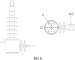
- the cross-sectional view of the connection between the outdoor jet type fuse 6 and the installation board 603 is illustrated in FIG. 8 .
- the design integrating the inlet line on the fuse and the static contact base of the isolating switch is realized, and the ZW32-type column installed circuit breaker, the electric isolating switch and the jet type fuse are combined into one with integrated design and complete set.
- annular groove 614 is set on the bottom of the epoxy resin base 612.
- the epoxy resin base 612 is installed on the bottom, and the sealing plate 610 is installed on the bottom of the epoxy resin base 612.
- the arc-suppressing tube 608 is set in the base.
- the fusion tube 607 is set in the arc-suppressing tube 608.
- the connecting tube 606 is set on the fusion tube 607.
- the upper movable contact 605 is set in the connecting tube 606.
- the lower static contact 611 is set below the arc-suppressing tube 608.
- the lower static contact 611 is connected to the outlet connection port 604 through a conductive tape.
- the marking part 609 is set on the bottom of the lower static contact 611.
- the lower movable contact 613 is set below the fusion tube 607.
- the lower movable contact 613 is in full and firm contact with the lower static contact 611.
- the bottom of the fusion tube 607 is covered with a booster spring, and the installation board 603 is set on the epoxy resin base 612, which facilitates the fixation on the isolating switch.
- the installation board 603 is poured inside the epoxy resin together with the fuse.
- the annular groove 614 is dug below the base, which facilitates increasing creepage distance and improving insulating capability.
- the fault current causes the fuse in the fusion tube 607 to fuse rapidly and form an arc.
- the gas in the arc-suppressing tube 608 is burned by the arc and causes a high pressure.
- An arc blow along the piping is formed.
- the arc is rapidly stretched and extinguished to form an electrical fracture, such that the faulty line or faulty device may be cut off.
- the marking part 609 pops out under action of a spring, which facilitates the detection and replacement by the maintainer.
- the fuse fixed structure of a composite material mechanism is adopted to replace the traditional ceramic support structure, which effectively reduces the problem of cracking of the ceramic support structure after opening failure of the fuse.
- a fuse of a vertical downward sealing structure is adopted, which enables a compact installing, a convenient operation and a strong environmental resistance.
- the disclosure provides a smart outdoor switchgear for control and protection of connection and disconnection of a medium-voltage microgrid, which includes: a current transformer, an isolating switch mechanism, an outdoor circuit breaker, an electric isolating driving mechanism and an outdoor jet type fuse.
- the current transformer is installed on an outlet end of the outdoor circuit breaker.
- the isolating switch mechanism is connected to the current transformer, and the isolating switch mechanism is connected to the outlet end of the outdoor circuit breaker through the current transformer.
- a top of the isolating switch mechanism on a side away from the current transformer is connected to a top of the outdoor jet type fuse, and a bottom of the isolating switch mechanism on the side away from the current transformer is connected to a bottom of the outdoor jet type fuse.
- the electric isolating driving mechanism is installed on the bottom of the isolating switch mechanism.
- the outdoor jet type fuse and the isolating switch mechanism are designed integrally, which solves the problem that the lead structure form of the outdoor jet type fuse cannot be integrally installed with the isolating switch mechanism.
Landscapes
- Engineering & Computer Science (AREA)
- Power Engineering (AREA)
- Physics & Mathematics (AREA)
- Electromagnetism (AREA)
- Driving Mechanisms And Operating Circuits Of Arc-Extinguishing High-Tension Switches (AREA)
- Catching Or Destruction (AREA)
Abstract
Description
- This application is based on and claims priority to
Chinese Patent Application No. 202310344268.6 filed on April 03, 2023 - ELECTRIC ISOLATING SWITCH", the entire contents of which are incorporated herein by reference in its entirety.
- The disclosure relates to, but is not limited to, the field of switchgear of medium-voltage outdoor circuit breaker and enclosed-type jet type fuse applied thereto, and in particular to a smart outdoor switchgear for control and protection of connection and disconnection of a medium-voltage microgrid.
- A circuit breaker is a switch apparatus which may make, carry and break current under normal circuit conditions, and may make, carry and break current under abnormal circuit conditions within a specified period of time. The circuit breaker may be used to distribute electrical energy and to achieve control and protection of power lines.
- An outdoor circuit breaker is generally installed on an outdoor telegraph pole. In order to fully ensure safe operation of the entire line, a fuse is generally further configured on a high-voltage side of a 12kV (kilovolt) distribution transformer or on a trunk line of the distribution line, which can achieve the protection of short-circuit and overload of the transformer and the line. Compared to an indoor circuit breaker, the operating environment of the outdoor circuit breaker is worse, and manual closing and opening operations on the isolating switch requires the help of special work. The operation thereof is difficult, and the whole process is complex.
- As to the shortcomings of the related art, an embodiment of the disclosure provides a smart outdoor switchgear for control and protection of connection and disconnection of a medium-voltage microgrid, which includes: a current transformer 1, an
isolating switch mechanism 2, an outdoor circuit breaker, an electricisolating driving mechanism 5 and an outdoorjet type fuse 6. - The current transformer 1 is installed on an outlet end of the outdoor circuit breaker. The
isolating switch mechanism 2 is connected to the current transformer 1, and theisolating switch mechanism 2 is connected to the outlet end of the outdoor circuit breaker through the current transformer 1. A top of theisolating switch mechanism 2 on a side away from the current transformer 1 is connected to a top of the outdoorjet type fuse 6, and a bottom of theisolating switch mechanism 2 on the side away from the current transformer 1 is connected to a bottom of the outdoorjet type fuse 6. The electricisolating driving mechanism 5 is installed on the bottom of theisolating switch mechanism 2. - In some embodiments, the
isolating switch mechanism 2 may include a currenttransformer support column 201, a driving mechanism, a base frame, a knifeswitch support column 205, anisolating insulating board 210 and aknife switch 211. - The base frame is set on a bottom of the outdoor circuit breaker and is on a same side as the current transformer 1. The current
transformer support column 201 and the knifeswitch support column 205 are set on the base frame, and the current transformer 1 is installed on ends of the currenttransformer support column 201 and the knifeswitch support column 205 away from the base frame. An end of theknife switch 211 is fixed on the knifeswitch support column 205, and a middle section of theknife switch 211 is connected to the driving mechanism by a pin shaft. An end of the driving mechanism away from theknife switch 211 is connected to the base frame. The electricisolating driving mechanism 5 is set on a side of the base frame. The electricisolating driving mechanism 5 is connected to the driving mechanism, and the electricisolating driving mechanism 5 is configured to drive the driving mechanism and to realize opening and closing of theknife switch 211. The isolatinginsulating board 210 is installed between the base frame and the outdoorjet type fuse 6. - In some embodiments, the driving mechanism may include a
driving shaft 204, aholding crank arm 206, a drivingcrank arm 207 and a driving connectingrod 209. - The
driving shaft 204 runs through the base frame, and the electricisolating driving mechanism 5 is connected to thedriving shaft 204. The electricisolating driving mechanism 5 is configured to drive thedriving shaft 204 and to realize the opening and the closing of theknife switch 211. Theholding crank arm 206 and thedriving crank arm 207 are set on thedriving shaft 204 at an interval by pin shafts, and thedriving shaft 204 is connected to an end of theholding crank arm 206 and an end of the drivingcrank arm 207 respectively. Another end of theholding crank arm 206 is installed on the base frame, and another end of the drivingcrank arm 207 is connected to theknife switch 211 through the driving connectingrod 209. - In some embodiments, the base frame may include a
right board 203 of the base frame, atransverse board 208 of the base frame, acrossbeam 212 of the base frame and aleft board 213 of the base frame. - The
right board 203 of the base frame and theleft board 213 of the base frame are set opposite each other. Each one of two ends of thedriving shaft 204 penetrates through a respective one of theright board 203 of the base frame and theleft board 213 of the base frame. Thetransverse board 208 of the base frame and thecrossbeam 212 of the base frame are set between theright board 203 of the base frame and theleft board 213 of the base frame. The outdoorjet type fuse 6 is set on a side of thetransverse board 208 of the base frame, and the isolatinginsulating board 210 is installed between thetransverse board 208 of the base frame and the outdoorjet type fuse 6. Thecrossbeam 212 of the base frame is installed on the bottom of the outdoor circuit breaker and is on the same side as the current transformer 1, and the electricisolating driving mechanism 5 is set on theleft board 213 of the base frame. - In some embodiments, the driving mechanism may further include a
manual operating lever 202. Themanual operating lever 202 is set on an end of thedriving shaft 204 penetrating through theright board 203 of the base frame. - In some embodiments, the electric
isolating driving mechanism 5 may include an opening mechanism, a closing mechanism and a stopper apparatus. The opening mechanism and the closing mechanism are set at an interval on an end of thedriving shaft 204 penetrating through theleft board 213 of the base frame, and the stopper apparatus is set between the opening mechanism and theleft board 213 of the base frame. - In some embodiments, the opening mechanism may include a
driving motor 502, adriving pinion 503, a drivengearwheel 504, amicro cam 505 and anopening stop switch 506. - The
driving motor 502 is installed on theleft board 213 of the base frame. A side of thedriving motor 502 away from theleft board 213 of the base frame is connected to thedriving pinion 503, and the drivengearwheel 504 is set above thedriving pinion 503. Thedriving pinion 503 is connected to the drivengearwheel 504 and drives the drivengearwheel 504 to rotate. The drivengearwheel 504 and themicro cam 505 are installed on thedriving shaft 204. - When the
driving shaft 204 rotates to an opening position, the drivengearwheel 504 drives themicro cam 505 and thedriving shaft 204 to simultaneously rotate to contact theopening stop switch 506, and theopening stop switch 506 operates to cut off a power supply of thedriving motor 502. - In some embodiments, the closing mechanism may include a
closing stop switch 501, adriving crank 507, a driving connectingrod 508 and an interlocking fixedplate 511. - An end of the
driving crank 507 is installed on thedriving shaft 204, and another end of thedriving crank 507 is installed on the driving connectingrod 508. An end of the driving connectingrod 508 away from thedriving crank 507 is connected to the interlocking fixedplate 511, and the interlocking fixedplate 511 is set on the outdoor circuit breaker. Thedriving shaft 204 drives thedriving crank 507 to rotate, and thedriving crank 507 drives the driving connectingrod 508 to move. - When the
driving shaft 204 rotates to a closing position, the drivengearwheel 504 drives themicro switch cam 505 and thedriving shaft 204 to simultaneously rotate to contact theclosing stop switch 501, and theclosing stop switch 501 operates to cut off the power supply of thedriving motor 502. - In some embodiments, the stopper apparatus may include a
lower stop block 509, amechanical block 510 and anupper stop block 512. - The
lower stop block 509 and theupper stop block 511 are installed on a sidewall of theleft board 213 of the base frame. Themechanical block 510 is installed on thedriving shaft 204. The opening mechanism is installed on an end of themechanical block 510 away from thedriving shaft 204. - When the
driving shaft 204 rotates counterclockwise under drive of thedriving motor 502, themechanical block 510 contacts thelower stop block 509, thelower stop block 509 restricts movement of themechanical block 510, and closing is in place. - When the
driving shaft 204 rotates clockwise under the drive of thedriving motor 502, themechanical block 510 contacts theupper stop block 512, theupper stop block 512 restricts the movement of themechanical block 510, and the closing is in place. - In some embodiments, the outdoor circuit breaker may include a
pole 3 of the outdoor circuit breaker and amechanism 4 of the outdoor circuit breaker. - The
pole 3 of the outdoor circuit breaker is installed on themechanism 4 of the outdoor circuit breaker. Themechanism 4 of the outdoor circuit breaker is installed on a side of theisolating switch mechanism 2, and an outlet end of thepole 3 of the outdoor circuit breaker is connected to the current transformer 1. - In some embodiments, the outdoor
jet type fuse 6 may include a contact assembly, a composite insulatingumbrella skirt 602, a loweroutlet connection port 604, anepoxy resin base 612 and asealing plate 610. - The composite insulating
umbrella skirt 602 is wrapped around an outer side of the contact assembly. Theepoxy resin base 612 is set on an end of the contact assembly, and theepoxy resin base 612 is connected to a bottom of a side of theisolating switch mechanism 2 away from the current transformer 1. Another end of the contact assembly away from theepoxy resin base 612 is connected to a top of the side of theisolating switch mechanism 2 away from the current transformer 1. The loweroutlet connection port 604 is set below the composite insulatingumbrella skirt 602, a lowerstatic contact 611 is connected to the loweroutlet connection port 604 through a conductive tape, and the sealingplate 610 is installed on a bottom of theepoxy resin base 612. - In some embodiments, the contact assembly may include an upper
static contact 601, an uppermovable contact 605, a connectingtube 606, afusion tube 607, an arc-suppressingtube 608, a markingpart 609, a lowermovable contact 613 and the lowerstatic contact 611. - The upper
static contact 601 is set above the composite insulatingumbrella skirt 602, and the upperstatic contact 601 is movably connected to theknife switch 211. An end of the upperstatic contact 601 away from theknife switch 211 is connected to the uppermovable contact 605. The connectingtube 606 is installed on an end of the uppermovable contact 605 away from the upperstatic contact 601. An end of the connectingtube 606 away from the uppermovable contact 605 is connected to thefusion tube 607. Thefusion tube 607 is set in the arc-suppressingtube 608. The arc-suppressingtube 608 is set in theepoxy resin base 612, and the lowerstatic contact 611 is installed below the arc-suppressingtube 608. The markingpart 609 is installed on a bottom of the lowerstatic contact 611. The lowermovable contact 613 is set below thefusion tube 607, and the lowermovable contact 613 is connected to the lower static contact 311. - In some embodiments, the outdoor
jet type fuse 6 may further include aninstallation board 603. Theinstallation board 603 is set on theepoxy resin base 612. Theinstallation board 603 is configured to install the outdoorjet type fuse 6 on the isolatingswitch mechanism 2, and theinstallation board 603 is poured outside with a layer of epoxy resin. - In some embodiments, an
annular groove 614 may be set on the bottom of theepoxy resin base 612. - Compared with the closest related art, the disclosure has the following beneficial effects.
- A smart outdoor switchgear for control and protection of connection and disconnection of a medium-voltage microgrid includes: a current transformer 1, an isolating
switch mechanism 2, an outdoor circuit breaker, an electric isolatingdriving mechanism 5 and an outdoorjet type fuse 6. The current transformer 1 is installed on an outlet end of the outdoor circuit breaker. The isolatingswitch mechanism 2 is connected to the current transformer 1, and the isolatingswitch mechanism 2 is connected to the outlet end of the outdoor circuit breaker through the current transformer 1. A top of the isolatingswitch mechanism 2 on a side away from the current transformer 1 is connected to a top of the outdoorjet type fuse 6, and a bottom of the isolatingswitch mechanism 2 on the side away from the current transformer 1 is connected to a bottom of the outdoorjet type fuse 6. The electric isolatingdriving mechanism 5 is installed on the bottom of the isolatingswitch mechanism 2. With the apparatus provided by the embodiments of the disclosure, the outdoorjet type fuse 6 and the isolatingswitch mechanism 2 are designed integrally, which solves the problem that the lead structure form of the outdoorjet type fuse 6 cannot be integrally installed with the isolatingswitch mechanism 2. The isolatingswitch mechanism 2 that adopts the electric isolatingdriving mechanism 5 may realize opening and closing without manual operations, and combines the outdoor circuit breaker, the electric isolatingdriving mechanism 5 and the outdoorjet type fuse 6 into one with integrated design and complete set. The structure of the apparatus is centralized and compact. The structural layout is reasonable. The space is compact. The installation is convenient. - The drawings here are incorporated into the specification and form a part of the specification. The drawings illustrate embodiments consistent with the disclosure and are used in combination with the specification to illustrate the technical solutions of the disclosure.
-
FIG. 1 is a diagram of a smart outdoor switchgear for control and protection of connection and disconnection of a medium-voltage microgrid. -
FIG. 2 is a first diagram of an isolating switch mechanism of a smart outdoor switchgear for control and protection of connection and disconnection of a medium-voltage microgrid. -
FIG. 3 is a second diagram of an isolating switch mechanism of a smart outdoor switchgear for control and protection of connection and disconnection of a medium-voltage microgrid. -
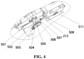
FIG. 4 is a diagram of a motor driving portion of an electric isolating driving mechanism of a smart outdoor switchgear for control and protection of connection and disconnection of a medium-voltage microgrid. -
FIG. 5 is a cross-sectional view of an electric isolating driving mechanism of a smart outdoor switchgear for control and protection of connection and disconnection of a medium-voltage microgrid. -
FIG. 6 is a side sectional view of a linkage protection scheme of an electric disconnector and an outdoor circuit breaker of a medium voltage intelligent grid connected protection device with fuse and electric disconnector. -
FIG. 7 is a side-sectional view of an outdoor jet type fuse of a smart outdoor switchgear for control and protection of connection and disconnection of a medium-voltage microgrid. -
FIG. 8 is a cross-sectional view of an outdoor jet type fuse of a smart outdoor switchgear for control and protection of connection and disconnection of a medium-voltage microgrid. - 1-current transformer, 2-isolating switch mechanism, 3-pole of the outdoor circuit breaker, 4-mechanism of the outdoor circuit breaker, 5-electric isolating driving mechanism, 6-outdoor jet type fuse, 201-current transformer support column, 202-manual operating lever, 203-right board of the base frame, 204-driving shaft, 205-knife switch support column, 206-holding crank arm, 207-driven crank arm, 208-transverse board of the base frame, 209-driving connecting rod, 210-isolating insulating board, 211-knife switch, 212-crossbeam of the base frame, 213-left board of the base frame, 501-closing stop switch, 502-driving motor, 503-driving pinion, 504-driven gearwheel, 505-micro cam, 506-opening stop switch, 507-driving crank, 508-driving connecting rod, 509-lower stop block, 510-mechanical block, 511-interlocking fixed plate, 512-upper stop block, 601-upper static contact, 602-composite insulating umbrella skirt, 603-installation board, 604-lower outlet connection port, 605-upper movable contact, 606-connecting tube, 607-fusion tube, 608-arc-suppressing tube, 609-marking part, 610-sealing plate, 611-lower static contact, 612-epoxy resin base, 613-lower movable contact, 614-annular groove.
- Specific implementations of the disclosure are illustrated in further detail below in combination with the drawings.
- An embodiment of the disclosure provides a smart outdoor switchgear for control and protection of connection and disconnection of a medium-voltage microgrid. As shown in
FIG. 1 , the apparatus includes: a current transformer 1, an isolatingswitch mechanism 2, an outdoor circuit breaker, an electric isolatingdriving mechanism 5 and an outdoorjet type fuse 6. - The current transformer 1 is installed on an outlet end of the outdoor circuit breaker. The isolating
switch mechanism 2 is connected to the current transformer 1, and the isolatingswitch mechanism 2 is connected to the outlet end of the outdoor circuit breaker through the current transformer 1. A top of the isolatingswitch mechanism 2 on a side away from the current transformer 1 is connected to the top of the outdoorjet type fuse 6, and a bottom of the isolatingswitch mechanism 2 on the side away from the current transformer 1 is connected to a bottom of the outdoorjet type fuse 6. The electric isolatingdriving mechanism 5 is installed on a bottom of the isolatingswitch mechanism 2. - A
pole 3 of the outdoor circuit breaker is installed on amechanism 4 of the outdoor circuit breaker, and an internal mechanism of themechanism 4 of the outdoor circuit breaker is actuated so as to realize the vacuum bubble opening and closing power system inside thepole 3 of the outdoor circuit breaker. The current transformer 1 is installed on the outlet end of the pole of the outdoor circuit breaker through a support column. The electric isolatingdriving mechanism 5 is installed on a side of aleft board 213 of the base frame, and the main function of the electric isolatingdriving mechanism 5 is to provide power for a drivingshaft 204 so as to realize opening and closing between aknife switch 211 and the power system. The outdoorjet type fuse 6 is installed in an installing hole on an inner side of atransverse board 208 of the base frame, and the entire outdoorjet type fuse 6 is side-installed. - As shown in
FIG. 2 , the isolatingswitch mechanism 2 includes a currenttransformer support column 201, a driving mechanism, a base frame, a knifeswitch support column 205, an isolating insulatingboard 210 and aknife switch 211. - The base frame is set on a bottom of the outdoor circuit breaker and is on a same side as the current transformer 1. The current
transformer support column 201 and the knifeswitch support column 205 are set on the base frame, and the current transformer 1 is installed on ends of the currenttransformer support column 201 and the knifeswitch support column 205 away from the base frame. An end of theknife switch 211 is fixed on the knifeswitch support column 205, and a middle section of theknife switch 211 is connected to the driving mechanism by a pin shaft. An end of the driving mechanism away from theknife switch 211 is connected to the base frame. The electric isolatingdriving mechanism 5 is set on a side of the base frame. The electric isolatingdriving mechanism 5 is connected to the driving mechanism, and the electric isolatingdriving mechanism 5 is configured to drive the driving mechanism and to realize opening and closing of theknife switch 211. The isolating insulatingboard 210 is installed between the base frame and the outdoorjet type fuse 6. - In some embodiments, the driving mechanism includes a driving
shaft 204, a holdingcrank arm 206, a drivingcrank arm 207 and adriving connecting rod 209. - The driving
shaft 204 runs through the base frame, and the electric isolatingdriving mechanism 5 is connected to the drivingshaft 204. The electric isolatingdriving mechanism 5 is configured to drive the drivingshaft 204 and to realize the opening and the closing of theknife switch 211. The holdingcrank arm 206 and the driving crankarm 207 are set on the drivingshaft 204 at an interval by pin shafts, and the drivingshaft 204 is connected to an end of the holding crankarm 206 and an end of the driving crankarm 207 respectively. The other end of the holding crankarm 206 is installed on the base frame, and the other end of the driving crankarm 207 is connected to theknife switch 211 through thedriving connecting rod 209. - In some embodiments, the base frame includes a
right board 203 of the base frame, atransverse board 208 of the base frame, acrossbeam 212 of the base frame and aleft board 213 of the base frame. - The
right board 203 of the base frame and theleft board 213 of the base frame are set opposite each other. Each one of two ends of the drivingshaft 204 penetrates through a respective one of theright board 203 of the base frame and theleft board 213 of the base frame. Thetransverse board 208 of the base frame and thecrossbeam 212 of the base frame are set between theright board 203 of the base frame and theleft board 213 of the base frame. The outdoorjet type fuse 6 is set on a side of thetransverse board 208 of the base frame, and the isolating insulatingboard 210 is installed between thetransverse board 208 of the base frame and the outdoorjet type fuse 6. Thecrossbeam 212 of the base frame is installed on the bottom of the outdoor circuit breaker and is on the same side as the current transformer 1, and the electric isolatingdriving mechanism 5 is set on theleft board 213 of the base frame. - In some embodiments, the driving mechanism further includes a
manual operating lever 202. Themanual operating lever 202 is set on an end of the drivingshaft 204 penetrating through theright board 203 of the base frame. - When an opening operation is performed by the outdoor circuit breaker, a tool is used to pull the
manual operating lever 202, so that the drivingshaft 204 is driven to rotate. The drivingshaft 204 is installed on the base frame consisting of theright board 203 of the base frame, thetransverse board 208 of the base frame, thecrossbeam 212 of the base frame etc.,. The drivingcrank arm 207 is installed on the drivingshaft 204, and thedriving connecting rod 209 is connected to the driving crankarm 207 by a pin shaft. An end of theknife switch 211 is connected to thedriving connecting rod 209 by a pin shaft, and the other end of theknife switch 211 is fixed on thesupport column 205. The drivingshaft 204 rotates and drives the driving crankarm 207 to rotate. The drivingcrank arm 207 drives thedriving connecting rod 209 to move upwardly to realize the opening operation. The current transformer 1 is installed above the currenttransformer support column 201 and the knifeswitch support column 205. The holdingcrank arm 206 is installed on the drivingshaft 204, and the main function of the holding crankarm 206 is to play a holding role for the knife switch of the entire isolating switch to ensure closing to be in place. The isolating insulatingboard 210 is installed between two elements, i.e., thetransverse board 208 of the base frame and the outdoorjet type fuse 6, which reduces the effects on the body of the isolating switch from the electric arc of faulty opening and closing of the fuse. - The outdoor jet type fuse is installed, so that a switchgear with multiple protection is formed, which may guarantee safety and reliability of the power transmission.
- The location of the electric isolating driving mechanism is shown in
FIG. 3 . The electric isolatingdriving mechanism 5 includes an opening mechanism, a closing mechanism and a stopper apparatus. The opening mechanism and the closing mechanism are set at an interval on an end of the drivingshaft 204 penetrating through theleft board 213 of the base frame, and the stopper apparatus is set between the opening mechanism and theleft board 213 of the base frame. - As shown in
FIG. 4 , the opening mechanism includes a drivingmotor 502, a drivingpinion 503, a drivengearwheel 504, amicro cam 505 and anopening stop switch 506. - The driving
motor 502 is installed on theleft board 213 of the base frame. A side of the drivingmotor 502 away from theleft board 213 of the base frame is connected to thedriving pinion 503, and the drivengearwheel 504 is set above the drivingpinion 503. The drivingpinion 503 is connected to the drivengearwheel 504 and drives the drivengearwheel 504 to rotate. The drivengearwheel 504 and themicro cam 505 are installed on the drivingshaft 204. - When the driving
shaft 204 rotates to an opening position, the drivengearwheel 504 drives themicro cam 505 and the drivingshaft 204 to simultaneously rotate to contact theopening stop switch 506, and theopening stop switch 506 operates to cut off a power supply of the drivingmotor 502. The cross-sectional view is illustrated inFIG. 5 . - When an electric operation is performed by the outdoor circuit breaker, the driving
motor 502 is installed on the side of theleft board 213 of the base frame and drives the drivingpinion 503 to rotate. The drivingpinion 503 drives the drivengearwheel 504 to operate. The drivengearwheel 504 is installed on the drivingshaft 204, and the drivengearwheel 504 rotates to drive the drivingshaft 204 to rotate, thereby completing the opening or closing operation. Themicro cam 505 is installed on the drivingshaft 204 and rotates with the drivingshaft 204 simultaneously. When the drivingshaft 204 rotates to the opening position, themicro switch cam 505 contacts theopening stop switch 506, and theopening stop switch 506 operates such that the power supply for the drivingmotor 502 is cut off. When the drivingshaft 204 rotates to a closing position, themicro switch cam 505 contacts theclosing stop switch 501, and theclosing stop switch 501 operates such that the power supply for the drivingmotor 502 is cut off. - An isolating switch that adopts an electric mechanism may realize opening and closing without manual operations. In addition, the operating reliability is ensured by electrical stopping and mechanical stopping.
- In some embodiments, the closing mechanism includes a
closing stop switch 501, a driving crank 507, adriving connecting rod 508 and an interlocking fixedplate 511. - An end of the driving crank 507 is installed on the driving
shaft 204, and the other end of the driving crank 507 is installed on thedriving connecting rod 508. An end of thedriving connecting rod 508 away from the driving crank 507 is connected to the interlocking fixedplate 511, and the interlocking fixedplate 511 is set on the outdoor circuit breaker. The drivingshaft 204 drives the driving crank 507 to rotate, and the driving crank 507 drives thedriving connecting rod 508 to move. - When the driving
shaft 204 rotates to a closing position, the drivengearwheel 504 drives themicro switch cam 505 and the drivingshaft 204 to simultaneously rotate to contact theclosing stop switch 501, and theclosing stop switch 501 operates to cut off the power supply of the drivingmotor 502. - When the isolating switch is in an opening state, an end of the driving crank 507 is installed on the driving
shaft 204, and another end of the driving crank 507 is installed on thedriving connecting rod 508. Another end of thedriving connecting rod 508 has an oblong hole connected to the interlocking fixedplate 511. When the drivingshaft 204 rotates, the drivingshaft 204 drives the driving crank 507 to rotate. The drivingcrank 507 rotates to drive the connectingrod 508 to move, and thedriving connecting rod 508 moves to drive the interlocking fixedplate 512 to rotate. When the drivingshaft 204 rotates to the closing position, the interlocking fixedplate 511 rotates to an interlocking position simultaneously. In such case, if the closing operation is performed by the circuit breaker, interlocking of the isolating switch and the circuit breaker is realized. If the opening operation is not performed by the circuit breaker, the isolating switch cannot be open. - Normally closed points of the
closing stop switch 501 and theopening stop switch 506 are respectively connected in series in the control circuit of the drivingmotor 502. After the closing or opening is in place, the normally closed point of theclosing stop switch 501 or the normally closed point of theopening stop switch 506 is switched to a normally open point. The control circuit of the drivingmotor 502 is disconnected such that the power supply for the drivingmotor 502 is cut off (the power supply of the drivingmotor 502 is cut off passively because the control circuit is disconnected). - The driving
motor 502 is a DC driving motor, and its forward and reverse (corresponding to moving directions of closing and opening) rotation instructions are given by a higher-level control system. - In some embodiments, the stopper apparatus includes a
lower stop block 509, amechanical block 510 and anupper stop block 512. - The
lower stop block 509 and the upper stop block 511 are installed on a sidewall of theleft board 213 of the base frame. Themechanical block 510 is installed on the drivingshaft 204, and the opening mechanism is installed on an end of themechanical block 510 away from the drivingshaft 204. - When the driving
shaft 204 rotates counterclockwise under drive of the drivingmotor 502, themechanical block 510 contacts thelower stop block 509, thelower stop block 509 restricts movement of themechanical block 510, and closing is in place. - When the driving
shaft 204 rotates clockwise under the drive of the drivingmotor 502, themechanical block 510 contacts theupper stop block 512, theupper stop block 512 restricts the movement of themechanical block 510, and the closing is in place. - The
lower stop block 509 and the upper stop block 512 are fixed on the sidewall of theleft board 213 of the base frame, and themechanical block 510 is installed on the drivingshaft 204. When the drivingshaft 204 rotates counterclockwise under the drive of the drivingmotor 502 and the movement reaches a certain stage, themechanical block 510 contacts thelower stop block 509, thelower block 509 restricts the movement of 510, and the closing is in place. When the drivingshaft 204 rotates clockwise under the drive of the drivingmotor 502 and the movement reaches a certain stage, themechanical block 510 contacts theupper stop block 512, theupper block 512 restricts the movement of 510, and the closing is in place. - In some embodiments, the outdoor circuit breaker includes a
pole 3 of the outdoor circuit breaker and amechanism 4 of the outdoor circuit breaker. - The
pole 3 of the outdoor circuit breaker is installed on themechanism 4 of the outdoor circuit breaker. Themechanism 4 of the outdoor circuit breaker is installed on a side of the isolatingswitch mechanism 2, and an outlet end of thepole 3 of the outdoor circuit breaker is connected to the current transformer 1. - As shown in
FIG. 6 , the outdoorjet type fuse 6 includes a contact assembly, a composite insulatingumbrella skirt 602, a loweroutlet connection port 604, anepoxy resin base 612 and asealing plate 610. - The composite insulating
umbrella skirt 602 is wrapped around an outer side of the contact assembly. Theepoxy resin base 612 is set on an end of the contact assembly, and theepoxy resin base 612 is connected to a bottom of a side of the isolatingswitch mechanism 2 away from the current transformer 1. Another end of the contact assembly away from theepoxy resin base 612 is connected to a top of the side of the isolatingswitch mechanism 2 away from the current transformer 1. The loweroutlet connection port 604 is set below the composite insulatingumbrella skirt 602, a lowerstatic contact 611 is connected to the loweroutlet connection port 604 through a conductive tape, and the sealingplate 610 is installed on a bottom of theepoxy resin base 612. - The upper contact structure form of the outdoor
jet type fuse 6 facilitates the realization of the opening and closing operations of the circuit breaker on the matched outdoor column. In addition, the side-installed manner may effectively protect the device from being damaged. - As shown in
FIG. 7 , the contact assembly includes an upperstatic contact 601, an uppermovable contact 605, a connectingtube 606, afusion tube 607, an arc-suppressingtube 608, a markingpart 609, a lowermovable contact 613 and the lowerstatic contact 611. - The upper
static contact 601 is set above the composite insulatingumbrella skirt 602, and the upperstatic contact 601 is movably connected to theknife switch 211. An end of the upperstatic contact 601 away from theknife switch 211 is connected to the uppermovable contact 605. The connectingtube 606 is installed on an end of the uppermovable contact 605 away from the upperstatic contact 601. An end of the connectingtube 606 away from the uppermovable contact 605 is connected to thefusion tube 607. Thefusion tube 607 is set in the arc-suppressingtube 608. The arc-suppressingtube 608 is set in theepoxy resin base 612, and the lowerstatic contact 611 is installed below the arc-suppressingtube 608. The markingpart 609 is installed on a bottom of the lowerstatic contact 611. The lowermovable contact 613 is set below thefusion tube 607, and the lowermovable contact 613 is connected to the lower static contact 311. - In some embodiments, the outdoor
jet type fuse 6 further includes aninstallation board 603. Theinstallation board 603 is set on theepoxy resin base 612. Theinstallation board 603 is configured to install the outdoorjet type fuse 6 on the isolatingswitch mechanism 2, and theinstallation board 603 is poured outside with a layer of epoxy resin. The cross-sectional view of the connection between the outdoorjet type fuse 6 and theinstallation board 603 is illustrated inFIG. 8 . - The design integrating the inlet line on the fuse and the static contact base of the isolating switch is realized, and the ZW32-type column installed circuit breaker, the electric isolating switch and the jet type fuse are combined into one with integrated design and complete set.
- In some embodiments, an
annular groove 614 is set on the bottom of theepoxy resin base 612. - The
epoxy resin base 612 is installed on the bottom, and the sealingplate 610 is installed on the bottom of theepoxy resin base 612. The arc-suppressingtube 608 is set in the base. Thefusion tube 607 is set in the arc-suppressingtube 608. The connectingtube 606 is set on thefusion tube 607. The uppermovable contact 605 is set in the connectingtube 606. The lowerstatic contact 611 is set below the arc-suppressingtube 608. The lowerstatic contact 611 is connected to theoutlet connection port 604 through a conductive tape. The markingpart 609 is set on the bottom of the lowerstatic contact 611. The lowermovable contact 613 is set below thefusion tube 607. The lowermovable contact 613 is in full and firm contact with the lowerstatic contact 611. The bottom of thefusion tube 607 is covered with a booster spring, and theinstallation board 603 is set on theepoxy resin base 612, which facilitates the fixation on the isolating switch. Theinstallation board 603 is poured inside the epoxy resin together with the fuse. Theannular groove 614 is dug below the base, which facilitates increasing creepage distance and improving insulating capability. - When a fault occurs in the system, the fault current causes the fuse in the
fusion tube 607 to fuse rapidly and form an arc. The gas in the arc-suppressingtube 608 is burned by the arc and causes a high pressure. An arc blow along the piping is formed. The arc is rapidly stretched and extinguished to form an electrical fracture, such that the faulty line or faulty device may be cut off. In addition, the markingpart 609 pops out under action of a spring, which facilitates the detection and replacement by the maintainer. - The fuse fixed structure of a composite material mechanism is adopted to replace the traditional ceramic support structure, which effectively reduces the problem of cracking of the ceramic support structure after opening failure of the fuse.
- A fuse of a vertical downward sealing structure is adopted, which enables a compact installing, a convenient operation and a strong environmental resistance.
- Finally, it is to be noted that the above embodiments are only used to illustrate the technical solutions of the disclosure rather than to limit the scope of protection. Although a detailed description of the disclosure is performed with reference to the above embodiments, those of ordinary skill in the art should understand that: those skilled in the art may still perform a variety of changes, modifications or equivalent replacements on the specific implementations of the disclosure after reading the disclosure, but these changes, modifications or equivalent replacements shall fall within the scope of protection of the pending claims of the disclosure.
- The disclosure provides a smart outdoor switchgear for control and protection of connection and disconnection of a medium-voltage microgrid, which includes: a current transformer, an isolating switch mechanism, an outdoor circuit breaker, an electric isolating driving mechanism and an outdoor jet type fuse. The current transformer is installed on an outlet end of the outdoor circuit breaker. The isolating switch mechanism is connected to the current transformer, and the isolating switch mechanism is connected to the outlet end of the outdoor circuit breaker through the current transformer. A top of the isolating switch mechanism on a side away from the current transformer is connected to a top of the outdoor jet type fuse, and a bottom of the isolating switch mechanism on the side away from the current transformer is connected to a bottom of the outdoor jet type fuse. The electric isolating driving mechanism is installed on the bottom of the isolating switch mechanism. The outdoor jet type fuse and the isolating switch mechanism are designed integrally, which solves the problem that the lead structure form of the outdoor jet type fuse cannot be integrally installed with the isolating switch mechanism.
Claims (14)
- A smart outdoor switchgear for control and protection of connection and disconnection of a medium-voltage microgrid, comprising: a current transformer (1), an isolating switch mechanism (2), an outdoor circuit breaker, an electric isolating driving mechanism (5) and an outdoor jet type fuse (6);
wherein the current transformer (1) is installed on an outlet end of the outdoor circuit breaker, the isolating switch mechanism (2) is connected to the current transformer (1), the isolating switch mechanism (2) is connected to the outlet end of the outdoor circuit breaker through the current transformer (1), a top of the isolating switch mechanism (2) on a side away from the current transformer (1) is connected to a top of the outdoor jet type fuse (6), a bottom of the isolating switch mechanism (2) on the side away from the current transformer (1) is connected to a bottom of the outdoor jet type fuse (6), and the electric isolating driving mechanism (5) is installed on a bottom of the isolating switch mechanism (2). - The apparatus of claim 1, wherein the isolating switch mechanism (2) comprises a current transformer support column (201), a driving mechanism, a base frame, a knife switch support column (205), an isolating insulating board (210) and a knife switch (211); and
the base frame is set on a bottom of the outdoor circuit breaker and is on a same side as the current transformer (1), the current transformer support column (201) and the knife switch support column (205) are set on the base frame, the current transformer (1) is installed on ends of the current transformer support column (201) and the knife switch support column (205) away from the base frame, an end of the knife switch (211) is fixed on the knife switch support column (205), a middle section of the knife switch (211) is connected to the driving mechanism by a pin shaft, an end of the driving mechanism away from the knife switch (211) is connected to the base frame, the electric isolating driving mechanism (5) is set on a side of the base frame, the electric isolating driving mechanism (5) is connected to the driving mechanism, the electric isolating driving mechanism (5) is configured to drive the driving mechanism and to realize opening and closing of the knife switch (211), and the isolating insulating board (210) is installed between the base frame and the outdoor jet type fuse (6). - The apparatus of claim 2, wherein the driving mechanism comprises a driving shaft (204), a holding crank arm (206), a driving crank arm (207) and a driving connecting rod (209); and
the driving shaft (204) runs through the base frame, the electric isolating driving mechanism (5) is connected to the driving shaft (204), the electric isolating driving mechanism (5) is configured to drive the driving shaft (204) and to realize the opening and the closing of the knife switch (211), the holding crank arm (206) and the driving crank arm (207) are set on the driving shaft (204) at an interval by pin shafts, the driving shaft (204) is connected to an end of the holding crank arm (206) and an end of the driving crank arm (207) respectively, another end of the holding crank arm (206) is installed on the base frame, and another end of the driving crank arm (207) is connected to the knife switch (211) through the driving connecting rod (209). - The apparatus of claim 3, wherein the base frame comprises a right board (203) of the base frame, a transverse board (208) of the base frame, a crossbeam (212) of the base frame and a left board (213) of the base frame; and
the right board (203) of the base frame and the left board (213) of the base frame are set opposite each other, each one of two ends of the driving shaft (204) penetrates through a respective one of the right board (203) of the base frame and the left board (213) of the base frame, the transverse board (208) of the base frame and the crossbeam (212) of the base frame are set between the right board (203) of the base frame and the left board (213) of the base frame, the outdoor jet type fuse (6) is set on a side of the transverse board (208) of the base frame, the isolating insulating board (210) is installed between the transverse board (208) of the base frame and the outdoor jet type fuse (6), the crossbeam (212) of the base frame is installed on the bottom of the outdoor circuit breaker and is on the same side as the current transformer (1), and the electric isolating driving mechanism (5) is set on the left board (213) of the base frame. - The apparatus of claim 4, wherein the driving mechanism further comprises a manual operating lever (202), and the manual operating lever (202) is set on an end of the driving shaft (204) penetrating through the right board (203) of the base frame.
- The apparatus of claim 4, wherein the electric isolating driving mechanism (5) comprises an opening mechanism, a closing mechanism and a stopper apparatus, the opening mechanism and the closing mechanism are set at an interval on an end of the driving shaft (204) penetrating through the left board (213) of the base frame, and the stopper apparatus is set between the opening mechanism and the left board (213) of the base frame.
- The apparatus of claim 6, wherein the opening mechanism comprises a driving motor (502), a driving pinion (503), a driven gearwheel (504), a micro cam (505) and an opening stop switch (506);the driving motor (502) is installed on the left board (213) of the base frame, a side of the driving motor (502) away from the left board (213) of the base frame is connected to the driving pinion (503), the driven gearwheel (504) is set above the driving pinion (503), the driving pinion (503) is connected to the driven gearwheel (504) and drives the driven gearwheel (504) to rotate, and the driven gearwheel (504) and the micro cam (505) are installed on the driving shaft (204); andwhen the driving shaft (204) rotates to an opening position, the driven gearwheel (504) drives the micro cam (505) and the driving shaft (204) to simultaneously rotate to contact the opening stop switch (506), and the opening stop switch (506) operates to cut off a power supply of the driving motor (502).
- The apparatus of claim 7, wherein the closing mechanism comprises a closing stop switch (501), a driving crank (507), a driving connecting rod (508) and an interlocking fixed plate (511);an end of the driving crank (507) is installed on the driving shaft (204), another end of the driving crank (507) is installed on the driving connecting rod (508), an end of the driving connecting rod (508) away from the driving crank (507) is connected to the interlocking fixed plate (511), the interlocking fixed plate (511) is set on the outdoor circuit breaker, the driving shaft (204) drives the driving crank (507) to rotate, and the driving crank (507) drives the driving connecting rod (508) to move; andwhen the driving shaft (204) rotates to a closing position, the driven gearwheel (504) drives the micro switch cam (505) and the driving shaft (204) to simultaneously rotate to contact the closing stop switch (501), and the closing stop switch (501) operates to cut off the power supply of the driving motor (502).
- The apparatus of claim 6, wherein the stopper apparatus comprises a lower stop block (509), a mechanical block (510) and an upper stop block (512);the lower stop block (509) and the upper stop block (511) are installed on a sidewall of the left board (213) of the base frame, the mechanical block (510) is installed on the driving shaft (204), and the opening mechanism is installed on an end of the mechanical block (510) away from the driving shaft (204);when the driving shaft (204) rotates counterclockwise under drive of a driving motor (502), the mechanical block (510) contacts the lower stop block (509), the lower stop block (509) restricts movement of the mechanical block (510), and closing is in place; andwhen the driving shaft (204) rotates clockwise under the drive of the driving motor (502), the mechanical block (510) contacts the upper stop block (512), the upper stop block (512) restricts the movement of the mechanical block (510), and the closing is in place.
- The apparatus of any one of claims 1 to 9, wherein the outdoor circuit breaker comprises a pole (3) of the outdoor circuit breaker and a mechanism (4) of the outdoor circuit breaker; and
the pole (3) of the outdoor circuit breaker is installed on the mechanism (4) of the outdoor circuit breaker, the mechanism (4) of the outdoor circuit breaker is installed on a side of the isolating switch mechanism (2), and an outlet end of the pole (3) of the outdoor circuit breaker is connected to the current transformer (1). - The apparatus of any one of claims 1 to 9, wherein the outdoor jet type fuse (6) comprises a contact assembly, a composite insulating umbrella skirt (602), a lower outlet connection port (604), an epoxy resin base (612) and a sealing plate (610); and
the composite insulating umbrella skirt (602) is wrapped around an outer side of the contact assembly, the epoxy resin base (612) is set on an end of the contact assembly, the epoxy resin base (612) is connected to a bottom of a side of the isolating switch mechanism (2) away from the current transformer (1), another end of the contact assembly away from the epoxy resin base (612) is connected to a top of the side of the isolating switch mechanism (2) away from the current transformer (1), the lower outlet connection port (604) is set below the composite insulating umbrella skirt (602), a lower static contact (611) is connected to the lower outlet connection port (604) through a conductive tape, and the sealing plate (610) is installed on a bottom of the epoxy resin base (612). - The apparatus of claim 11, wherein the contact assembly comprises an upper static contact (601), an upper movable contact (605), a connecting tube (606), a fusion tube (607), an arc-suppressing tube (608), a marking part (609), a lower movable contact (613) and the lower static contact (611); and
the upper static contact (601) is set above the composite insulating umbrella skirt (602), the upper static contact (601) is movably connected to a knife switch (211), an end of the upper static contact (601) away from the knife switch (211) is connected to the upper movable contact (605), the connecting tube (606) is installed on an end of the upper movable contact (605) away from the upper static contact (601), an end of the connecting tube (606) away from the upper movable contact (605) is connected to the fusion tube (607), the fusion tube (607) is set in the arc-suppressing tube (608), the arc-suppressing tube (608) is set in the epoxy resin base (612), the lower static contact (611) is installed below the arc-suppressing tube (608), the marking part (609) is installed on a bottom of the lower static contact (611), the lower movable contact (613) is set below the fusion tube (607), and the lower movable contact (613) is connected to the lower static contact (311). - The apparatus of claim 12, wherein the outdoor jet type fuse (6) further comprises an installation board (603), the installing board (603) is set on the epoxy resin base (612), the installing board (603) is configured to install the outdoor jet type fuse (6) on the isolating switch mechanism (2), and the installing board (603) is poured outside with a layer of epoxy resin.
- The apparatus of claim 11, wherein an annular groove (614) is set on the bottom of the epoxy resin base (612).
Applications Claiming Priority (2)
| Application Number | Priority Date | Filing Date | Title |
|---|---|---|---|
| CN202310344268.6A CN116418039A (en) | 2023-04-03 | 2023-04-03 | A medium-voltage intelligent grid-connected protection device with fuses and electric isolating switches |
| PCT/CN2023/139100 WO2024149021A1 (en) | 2023-04-03 | 2023-12-15 | Intelligent outdoor combination electrical device for grid-connected and off-grid control protection of medium-voltage microgrid |
Publications (3)
| Publication Number | Publication Date |
|---|---|
| EP4421840A1 true EP4421840A1 (en) | 2024-08-28 |
| EP4421840A4 EP4421840A4 (en) | 2025-03-05 |
| EP4421840B1 EP4421840B1 (en) | 2026-02-04 |
Family
ID=87055912
Family Applications (1)
| Application Number | Title | Priority Date | Filing Date |
|---|---|---|---|
| EP23866683.8A Active EP4421840B1 (en) | 2023-04-03 | 2023-12-15 | Intelligent outdoor combination electrical device for grid-connected and off-grid control protection of medium-voltage microgrid |
Country Status (4)
| Country | Link |
|---|---|
| US (1) | US20250246388A1 (en) |
| EP (1) | EP4421840B1 (en) |
| CN (1) | CN116418039A (en) |
| WO (1) | WO2024149021A1 (en) |
Families Citing this family (5)
| Publication number | Priority date | Publication date | Assignee | Title |
|---|---|---|---|---|
| CN116418039A (en) * | 2023-04-03 | 2023-07-11 | 中国电力科学研究院有限公司 | A medium-voltage intelligent grid-connected protection device with fuses and electric isolating switches |
| CN118116765A (en) * | 2024-03-18 | 2024-05-31 | 信尔德科技有限公司 | Electric isolation device |
| CN119480533B (en) * | 2024-12-26 | 2025-09-16 | 信尔德科技有限公司 | Ground switch double-control structure of electric isolation sectioning device |
| CN120637148A (en) * | 2025-06-24 | 2025-09-12 | 火炬电气集团有限公司 | A 10KV outdoor vacuum circuit breaker |
| CN120878514B (en) * | 2025-09-04 | 2026-05-12 | 江苏宏达电气有限公司 | Double-error-closing-prevention depth fusion circuit breaker with isolating switch |
Family Cites Families (11)
| Publication number | Priority date | Publication date | Assignee | Title |
|---|---|---|---|---|
| KR101104145B1 (en) * | 2010-10-01 | 2012-01-13 | 성화종합전기(주) | Phase-shielded insulated compact load switch with integrated detector and arrester |
| CN201966163U (en) * | 2011-01-24 | 2011-09-07 | 南京紫洋电力设备有限公司 | Outdoor alternating current isolation enclosed type jet fuse |
| CN202601497U (en) * | 2012-03-14 | 2012-12-12 | 浙江国源电气有限公司 | Automatic recloser |
| CN207425767U (en) * | 2017-08-09 | 2018-05-29 | 上海华坤电器有限公司 | A kind of open air all insulation enclosed type expulsion fuse |
| CN108962666B (en) * | 2018-09-21 | 2024-04-09 | 江苏江阴华明电气设备有限公司 | An intelligent outdoor high-voltage AC vacuum load switch |
| CN208834975U (en) * | 2018-09-25 | 2019-05-07 | 乾瑞电气有限公司 | Vacuum circuit breaker on outdoor lamppost |
| CN208889594U (en) * | 2018-11-09 | 2019-05-21 | 国网陕西省电力公司渭南供电公司 | Novel high-pressure expulsion fuse |
| CN217361385U (en) * | 2021-10-11 | 2022-09-02 | 江苏大烨智能电气股份有限公司 | Bilateral operation isolating switch device |
| CN216597483U (en) * | 2022-01-21 | 2022-05-24 | 正勤电气(沈阳)有限公司 | Electric isolating switch for 10kV pole-mounted circuit breaker |
| CN217933517U (en) * | 2022-04-24 | 2022-11-29 | 河南华盛隆源电气有限公司 | Circuit breaker with external disconnecting switch |
| CN116418039A (en) * | 2023-04-03 | 2023-07-11 | 中国电力科学研究院有限公司 | A medium-voltage intelligent grid-connected protection device with fuses and electric isolating switches |
-
2023
- 2023-04-03 CN CN202310344268.6A patent/CN116418039A/en active Pending
- 2023-12-15 WO PCT/CN2023/139100 patent/WO2024149021A1/en not_active Ceased
- 2023-12-15 EP EP23866683.8A patent/EP4421840B1/en active Active
- 2023-12-15 US US18/699,950 patent/US20250246388A1/en active Pending
Also Published As
| Publication number | Publication date |
|---|---|
| EP4421840A4 (en) | 2025-03-05 |
| US20250246388A1 (en) | 2025-07-31 |
| WO2024149021A1 (en) | 2024-07-18 |
| CN116418039A (en) | 2023-07-11 |
| EP4421840B1 (en) | 2026-02-04 |
Similar Documents
| Publication | Publication Date | Title |
|---|---|---|
| EP4421840B1 (en) | Intelligent outdoor combination electrical device for grid-connected and off-grid control protection of medium-voltage microgrid | |
| CN102037534B (en) | Circuit breaker with high speed mechanically-interlocked grounding switch | |
| WO2018086456A1 (en) | Double-break isolating switch having grounding linkage | |
| EP0745262B1 (en) | High performance circuit breaker with independent pole operation linkage and conical composite bushings | |
| JP5078067B2 (en) | Vacuum circuit interrupter | |
| WO2018090548A1 (en) | Double-break isolated switch module | |
| CN112216550A (en) | Pole-mounted circuit breaker with built-in isolating switch | |
| CN106848909A (en) | One kind is without isolated switchgear under bin static contact non-SF 6 gas insulative | |
| CN116844910B (en) | Isolation built-in all-insulation column type deep fusion circuit breaker and interlocking method | |
| CN120149087A (en) | An outdoor high-voltage combined electrical device for preventing errors in electrified railways | |
| CN222883436U (en) | Outdoor pole-mounted circuit breaker with secondary fusion | |
| CN216353930U (en) | GIS is with two break isolator | |
| CN220358822U (en) | A medium-voltage intelligent grid-connected protection device with fuse and electric isolating switch | |
| CN111627746B (en) | A vacuum switch device | |
| CN207338183U (en) | Vacuum circuit breaker constructions | |
| CN111554534B (en) | Quick-closing high-voltage isolating switch | |
| KR101095016B1 (en) | 3-position operation device of gas insulated switchgear | |
| CN108461333B (en) | Linkage operating mechanism | |
| CN208208640U (en) | A kind of outdoor high-voltage isolating switch | |
| CN201886957U (en) | Indoor high-voltage alternating current (AC) vacuum circuit breaker | |
| KR102230069B1 (en) | Driving apparatus interlocked vacuum interrupter and disconnector of load break wwitch | |
| EP2620969B1 (en) | High-voltage electrical switchgear | |
| CN116741565A (en) | Three-station isolating switch device and inflatable cabinet | |
| CN112951682B (en) | An integrated combination device of a circuit breaker isolating switch | |
| CN114496644B (en) | Insulated switch module and direct-acting air-insulated circuit breaker switch |
Legal Events
| Date | Code | Title | Description |
|---|---|---|---|
| STAA | Information on the status of an ep patent application or granted ep patent |
Free format text: STATUS: UNKNOWN |
|
| STAA | Information on the status of an ep patent application or granted ep patent |
Free format text: STATUS: THE INTERNATIONAL PUBLICATION HAS BEEN MADE |
|
| PUAI | Public reference made under article 153(3) epc to a published international application that has entered the european phase |
Free format text: ORIGINAL CODE: 0009012 |
|
| STAA | Information on the status of an ep patent application or granted ep patent |
Free format text: STATUS: REQUEST FOR EXAMINATION WAS MADE |
|
| 17P | Request for examination filed |
Effective date: 20240328 |
|
| AK | Designated contracting states |
Kind code of ref document: A1 Designated state(s): AL AT BE BG CH CY CZ DE DK EE ES FI FR GB GR HR HU IE IS IT LI LT LU LV MC ME MK MT NL NO PL PT RO RS SE SI SK SM TR |
|
| RIN1 | Information on inventor provided before grant (corrected) |
Inventor name: QIN, XINGQIANG Inventor name: LI, MINGMING Inventor name: ZHOU, KUN Inventor name: LI, JIA Inventor name: LIU, LU Inventor name: WU, YUNZHAO Inventor name: ZHANG, YAO Inventor name: MA, CHUNYAN Inventor name: SHA, GUANGLIN Inventor name: ZHAO, CAIHONG Inventor name: WANG, JUNKAI Inventor name: LIU, NING Inventor name: QI, HUI Inventor name: DUAN, QING Inventor name: SHENG, WANXING Inventor name: WANG, HAOQING |
|
| REG | Reference to a national code |
Ref country code: DE Ref legal event code: R079 Free format text: PREVIOUS MAIN CLASS: H01H0089000000 Ipc: H01H0031120000 Ref country code: DE Ref legal event code: R079 Ref document number: 602023011722 Country of ref document: DE Free format text: PREVIOUS MAIN CLASS: H01H0089000000 Ipc: H01H0031120000 |
|
| A4 | Supplementary search report drawn up and despatched |
Effective date: 20250203 |
|
| RIC1 | Information provided on ipc code assigned before grant |
Ipc: H01H 89/00 20060101ALN20250128BHEP Ipc: H02H 7/26 20060101ALI20250128BHEP Ipc: H02H 7/22 20060101ALI20250128BHEP Ipc: H01H 85/175 20060101ALI20250128BHEP Ipc: H01H 85/042 20060101ALI20250128BHEP Ipc: H01H 9/26 20060101ALI20250128BHEP Ipc: H01H 33/666 20060101ALI20250128BHEP Ipc: H01H 33/02 20060101ALI20250128BHEP Ipc: H01H 31/28 20060101ALI20250128BHEP Ipc: H01H 31/12 20060101AFI20250128BHEP Ipc: H02H 7/00 20060101ALI20250128BHEP |
|
| GRAP | Despatch of communication of intention to grant a patent |
Free format text: ORIGINAL CODE: EPIDOSNIGR1 |
|
| STAA | Information on the status of an ep patent application or granted ep patent |
Free format text: STATUS: GRANT OF PATENT IS INTENDED |
|
| RIC1 | Information provided on ipc code assigned before grant |
Ipc: H01H 31/12 20060101AFI20250918BHEP Ipc: H01H 31/28 20060101ALI20250918BHEP Ipc: H01H 33/02 20060101ALI20250918BHEP Ipc: H01H 33/666 20060101ALI20250918BHEP Ipc: H01H 9/26 20060101ALI20250918BHEP Ipc: H01H 85/042 20060101ALI20250918BHEP Ipc: H01H 85/175 20060101ALI20250918BHEP Ipc: H02H 7/00 20060101ALI20250918BHEP Ipc: H02H 7/22 20060101ALI20250918BHEP Ipc: H02H 7/26 20060101ALI20250918BHEP Ipc: H01H 89/00 20060101ALN20250918BHEP |
|
| RIC1 | Information provided on ipc code assigned before grant |
Ipc: H01H 31/12 20060101AFI20250919BHEP Ipc: H01H 31/28 20060101ALI20250919BHEP Ipc: H01H 33/02 20060101ALI20250919BHEP Ipc: H01H 33/666 20060101ALI20250919BHEP Ipc: H01H 9/26 20060101ALI20250919BHEP Ipc: H01H 85/042 20060101ALI20250919BHEP Ipc: H01H 85/175 20060101ALI20250919BHEP Ipc: H02H 7/00 20060101ALI20250919BHEP Ipc: H02H 7/22 20060101ALI20250919BHEP Ipc: H02H 7/26 20060101ALI20250919BHEP Ipc: H01H 89/00 20060101ALN20250919BHEP |
|
| DAV | Request for validation of the european patent (deleted) | ||
| DAX | Request for extension of the european patent (deleted) | ||
| INTG | Intention to grant announced |
Effective date: 20251008 |
|
| GRAS | Grant fee paid |
Free format text: ORIGINAL CODE: EPIDOSNIGR3 |
|
| GRAA | (expected) grant |
Free format text: ORIGINAL CODE: 0009210 |
|
| STAA | Information on the status of an ep patent application or granted ep patent |
Free format text: STATUS: THE PATENT HAS BEEN GRANTED |
|
| AK | Designated contracting states |
Kind code of ref document: B1 Designated state(s): AL AT BE BG CH CY CZ DE DK EE ES FI FR GB GR HR HU IE IS IT LI LT LU LV MC ME MK MT NL NO PL PT RO RS SE SI SK SM TR |
|
| REG | Reference to a national code |
Ref country code: CH Ref legal event code: F10 Free format text: ST27 STATUS EVENT CODE: U-0-0-F10-F00 (AS PROVIDED BY THE NATIONAL OFFICE) Effective date: 20260204 Ref country code: GB Ref legal event code: FG4D |
|
| REG | Reference to a national code |
Ref country code: DE Ref legal event code: R096 Ref document number: 602023011722 Country of ref document: DE |
|
| REG | Reference to a national code |
Ref country code: IE Ref legal event code: FG4D |