WO2018086456A1 - Double-break isolating switch having grounding linkage - Google Patents
Double-break isolating switch having grounding linkage Download PDFInfo
- Publication number
- WO2018086456A1 WO2018086456A1 PCT/CN2017/107459 CN2017107459W WO2018086456A1 WO 2018086456 A1 WO2018086456 A1 WO 2018086456A1 CN 2017107459 W CN2017107459 W CN 2017107459W WO 2018086456 A1 WO2018086456 A1 WO 2018086456A1
- Authority
- WO
- WIPO (PCT)
- Prior art keywords
- switch
- grounding
- double
- isolating
- transmission
- Prior art date
- Legal status (The legal status is an assumption and is not a legal conclusion. Google has not performed a legal analysis and makes no representation as to the accuracy of the status listed.)
- Ceased
Links
Images



Classifications
-
- H—ELECTRICITY
- H01—ELECTRIC ELEMENTS
- H01H—ELECTRIC SWITCHES; RELAYS; SELECTORS; EMERGENCY PROTECTIVE DEVICES
- H01H31/00—Air-break switches for high tension without arc-extinguishing or arc-preventing means
- H01H31/02—Details
- H01H31/04—Interlocking mechanisms
- H01H31/10—Interlocking mechanisms for interlocking two or more switches
-
- H—ELECTRICITY
- H01—ELECTRIC ELEMENTS
- H01H—ELECTRIC SWITCHES; RELAYS; SELECTORS; EMERGENCY PROTECTIVE DEVICES
- H01H31/00—Air-break switches for high tension without arc-extinguishing or arc-preventing means
- H01H31/02—Details
- H01H31/023—Base and stationary contacts mounted thereon
-
- H—ELECTRICITY
- H01—ELECTRIC ELEMENTS
- H01H—ELECTRIC SWITCHES; RELAYS; SELECTORS; EMERGENCY PROTECTIVE DEVICES
- H01H31/00—Air-break switches for high tension without arc-extinguishing or arc-preventing means
- H01H31/02—Details
- H01H31/026—Movable parts and contacts mounted thereon
Definitions
- the invention relates to the field of equipment of a converter station/substation of a voltage level of 220 kV and above, and more particularly to a double-break isolation switch with ground linkage.
- Isolation switch (commonly known as "knife gate”), generally refers to the high-voltage isolating switch, that is, the isolating switch with rated voltage above 1kV, usually referred to as the isolating switch, is the most used one of the high-voltage switchgear, its own work
- the principle and structure are relatively simple, but due to the large amount of use and high reliability requirements, the impact on the design, establishment and safe operation of substations and power plants is large.
- the main feature of the isolating switch is that it has no arc extinguishing capability and can only divide and close the circuit without load current.
- the isolating switch is used for voltages at various stages. It is used to change the circuit connection or to isolate the line or equipment from the power supply.
- the first stage the traditional GIS knife gate design generally uses the isolation knife gate and the grounding knife gate as two independent functional units.
- the isolation knife gate In present, there are still many mainstream manufacturers adopting this design, in order to avoid the isolation knife gate during the knife gate operation.
- the brake When the brake is energized, the grounding knife gate is mismatched and the grounding isolation knife is prevented from being grounded.
- the grounding can only be controlled by electrical interlock. If the electrical interlocking circuit fails or is unlocked incorrectly, the grid line trip may be triggered. accident.
- the second stage three-station isolation knife gate design.
- the design integrates the features and functions of the isolating knife gate and the grounding knife gate. It has three working positions: 1. the closing position of the main breaker of the isolation knife gate; the isolation position of the main breaker of the isolation knife gate; 3 grounding The grounding position of the knife gate closing.
- the three-station isolation knife gate is based on the electrical interlock control of the traditional GIS knife gate, and introduces the mechanical interlocking control function to form double interlocking control, which is equivalent to double insurance, which greatly reduces the occurrence of switching due to electrical or mechanical interlock failure. The probability of a grid accident that is mishandled.
- the three-station isolation knife gate realizes that the knife gate has only one moving contact, and the two ends of the movable contact are the isolated fracture end and the ground end respectively, so the working position of the movable contact at any moment is unique. Either the flow is closed with the isolation fracture end, or it is grounded with the ground terminal, or neither flow nor ground.
- the mechanical state of the knife gate contacts basically eliminates the possibility of misoperation.
- a first object of the present invention is to provide a four station isolation knife gate having two isolation fractures.
- the second object of the present invention is that the grounding operation can be performed through the grounding knife gate in the middle of the isolation fracture, and the grounding knife gate and the isolating knife gate are interlocked to prevent misoperation.
- Double-breaking isolating switch with grounding linkage comprising shell, double-break switch device, disconnecting switch driving device, grounding switch device, grounding switch driving device, grounding switch transmission mechanism, linkage device; said double-break switch device installation Inside the casing, the synchronous switch closing or opening of the two sides of the fracture is realized by the isolating switch driving device; the grounding switch device is mounted on the casing to perform grounding opening and closing control of the double-breaking switch device, which passes The grounding switch driving device and the grounding switch transmission mechanism realize closing or opening; the linkage device is respectively connected with the isolating switch driving device and the grounding switch driving device, so that the grounding switching device can be performed when the double-breaking switching device is in the opening state When the grounding switch device is in the open state, the double-fracture switch device can be closed; the housing is provided with a plurality of closed cavities that are sequentially connected, and each of the cavities is correspondingly provided with one Group double break switch device, grounding switch device.
- the isolating switch driving device comprises an isolating switch motor, an isolating switch output shaft, and an isolating switch control circuit for controlling the isolating switch motor;
- the grounding switch driving device comprises grounding connected in sequence a switch motor, a grounding switch output shaft, a grounding switch control circuit for controlling the grounding switch motor;
- the linkage device includes a first micro switch and a second micro switch; and the first micro switch is connected to the isolating switch at one end The other end of the output shaft is connected to the grounding switch control loop; one end of the second microswitch is connected to the grounding switch, and the other end is connected to the isolating switch control loop;
- the first microswitch is controlled by detecting the positional relationship of the output shaft of the isolating switch
- the grounding switch control circuit is turned on or off; the second micro switch controls the on/off of the isolating switch control circuit by detecting the positional relationship of the grounding switch output shaft.
- the first micro switch and the second micro switch are a lever roller type, and the output switch shaft of the isolation switch is provided with a first touch groove matched with the roller of the first micro switch.
- the first micro switch is installed outside the output shaft of the isolating switch and its roller corresponds to the positional relationship of the first touch groove;
- the grounding switch output shaft is provided with a roller matched with the second micro switch Two-touch groove;
- the second micro switch is installed outside the grounding switch output shaft and its roller corresponds to the second touch groove position relationship; the roller of the first micro switch is engaged with the first touch groove at the initial
- the double-break switch device is in the open state, the grounding switch control circuit is connected, the output switch of the isolating switch is turned one week, the double-break switch device is in the closing state, the grounding switch control circuit is cut off, the output shaft of the isolating switch is reversed for one week, double-break The switch device resumes the opening state; when the roller of the second micro switch is
- the driving box is further disposed on the outer side of the casing, and the isolating switch driving device, the grounding switch driving device and the linkage device are all disposed in the driving box.
- the grounding switch transmission mechanism includes a first rocker arm, a first link, a second rocker arm, and a second link; an end of the first rocker arm and an output of the grounding switch driving device
- the second rocker arm is disposed on the grounding switch device for operating the closing or opening of the grounding switch device, and the swinging end of the first rocker arm and the second rocker arm is connected by the first connecting rod
- the oscillating ends of the second rocker arms of the plurality of grounding switch devices are connected by a second link.
- the double-fracture switch device includes a movable contact holder, a pair of movable contacts and a pair of static contacts;
- the movable contact seat is disposed at a middle portion of the cavity;
- a pair of static contacts are respectively disposed on opposite sides of the movable contact seat;
- the pair of movable contacts are disposed inside the movable contact holder and can protrude from the opposite direction to the movable contact holder and corresponding
- the static contact contact fits, the pair of movable contacts are synchronously reciprocating linear motion by the driving mechanism, and simultaneously or simultaneously separated from the static contact; the pair of movable contacts are electrically connected to each other.
- the existing product isolation switch In the process of opening and closing the busbar conversion current, the existing product isolation switch has only one fracture, and the arcing time is longer, which is not conducive to arc extinguishing, and the moving contact ablation is serious.
- the easy product metal powder is not conducive to product insulation.
- Performance, double-break isolation switch can be installed with arc contacts on both sides due to the two partial pressure division and arc extinguishing, which greatly reduces the arcing time, reduces the burning loss of copper and tungsten contacts, and improves the service life of the product. And performance.
- an end of the moving contact facing away from the static contact is provided with an axially arranged rack that cooperates with the driving mechanism.
- the driving mechanism includes an insulating transmission rod, a transmission gear, a transmission shaft, a transmission insert;
- the transmission shaft is a spline shaft, and is connected to the isolating switch driving device;
- the shaft position of the transmission insert is provided with a spline blind hole that cooperates with the outer circumference of the spline shaft;
- the axial position of the transmission gear is provided with a spline through hole that cooperates with the outer circumference of the spline shaft, and the outer circumference of the transmission gear is an external gear portion that cooperates with the rack;
- the two ends of the insulated transmission rod are coaxial Fixing a transmission insert, the spline blind hole of the transmission insert facing outward;
- the transmission gear is disposed inside the movable contact seat and the external gear portion and the teeth of the pair of moving contacts
- the gear shaft passes through the spline through hole of the transmission gear, one end of the transmission shaft is connected with the transmission insert of one end of the insulating transmission rod,
- the double-break isolation switch module adopts three-phase linkage mechanical transmission structure, and the transmission is stable and reliable.
- the built-in transmission structure design without exposed connecting rod enhances the weather resistance of key components of the product, reduces the transmission link, and improves the transmission efficiency of the separation and operation of the isolated knife gate.
- the grounding switch can be closed. Similarly, only when the grounding switch is opened, the isolating switch can perform the closing operation to avoid manual misoperation and improve equipment safety.
- FIG. 1 is a schematic perspective structural view of a double-breaking isolating switch with grounding linkage according to the present invention.
- FIG. 2 is a schematic vertical structural view of a double-break disconnecting switch with grounding linkage according to the present invention.
- Fig. 3 is an enlarged schematic view showing a region A of Fig. 2;
- FIG. 4 is a schematic cross-sectional structural view of a double-break disconnecting switch with grounding linkage according to the present invention.
- Figure 5 is a schematic view showing the internal structure of the drive box of the present invention.
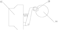
- FIG. 6 is a schematic view showing the cooperation of the first micro switch and the output shaft of the isolating switch of the present invention.
- FIG. 7 is a schematic view showing the cooperation of the second micro switch and the grounding switch output shaft of the present invention.
- Figure 8 is a schematic structural view of the linkage of the present invention.
- a double-breaking isolating switch with grounding linkage includes a housing 1, a double-break switch device 2, an isolating switch driving device 3, a grounding switch device 4, a grounding switch driving device 5, and a grounding switch.
- the transmission mechanism 6, the linkage device 7, the driving box 8, the driving box 8 is disposed outside the casing 1, and the isolating switch driving device 3, the grounding switch driving device 5, and the linkage device 7 are all disposed in the driving box 8.
- the double-break switch device 2 is installed inside the casing 1, and realizes synchronous closing or opening of the two-side fractures through the isolating switch driving device 3; the grounding switch device 4 is mounted on the casing 1
- the double-break switch device 2 performs grounding opening and closing control, which is closed or opened by the grounding switch driving device 5 and the grounding switch transmission mechanism 6; the linkage device 7 and the isolating switch driving device 3 and the grounding switch respectively
- the driving device 5 is connected so that the grounding switch device 4 can be closed when the double-break switch device 2 is in the open state; or the double-break switch device 2 can be combined when the ground switch device 4 is in the open state.
- the housing 1 equipped with three successively communicating chamber 9 closed, corresponding to each of said inner cavity 9 is provided with a set of double-break switching device 2, the grounding switching device 4.
- the isolating switch driving device 3 includes an isolating switch motor 10 connected in sequence, an isolating switch output shaft 11, an isolating switch control circuit 12 for controlling the isolating switch motor 10, and the grounding switch driving device.
- the linkage device 7 includes a first micro switch 16 and a second micro switch 17 One end of the first micro switch 16 is connected to the other end of the isolating switch output shaft 11 and is connected to the grounding switch control circuit 15; one end of the second micro switch 17 is connected to the grounding switch output shaft 14 and the other end is connected to the isolating switch control circuit 12
- the first micro switch 16 controls the on or off of the ground switch control circuit 15 by detecting the positional relationship of the isolating switch output shaft 11; the second micro switch 17 detects the position of the ground switch output shaft 14 by detecting The relationship controls the switch on or off of the isolation switch control circuit 12.
- the first micro switch 16 and the second micro switch 17 are of a lever roller type, and the isolating switch output shaft 11 is provided with a roller of the first micro switch 16 .
- the grounding switch transmission mechanism 6 includes a first rocker arm 20, a first link 21, a second rocker arm 22, and a second link 23; one end of the first rocker arm 20 is The output of the grounding switch drive 5 is connected, and the second rocker arm 22 is disposed on the grounding switch device 4 for operating the closing or opening of the grounding switch device 4, the first rocker arm 20 and the second The oscillating ends of the rocker arms 22 are connected by a first link 21; the oscillating ends of the second rocker arms 22 of the plurality of grounding switch devices 4 are connected by a second link 23.
- the double-break switch device 2 includes a movable contact holder 24, a pair of movable contacts 25 and a pair of fixed contacts 26; the movable contact 25 seat 24 is disposed at the a middle portion of the cavity 9; the pair of static contacts 26 are respectively disposed at opposite sides of the movable contact 25 seat 24; the pair of movable contacts 25 are disposed on the movable contact
- the 25-seat 24 is internal and can extend from the opposite direction to move the contact 25 seat 24 into contact with the corresponding fixed contact 26, and the pair of movable contacts 25 are synchronously reciprocating linear motion by the driving mechanism 27, and the static touch
- the heads 26 are simultaneously contacted or simultaneously separated; the pair of movable contacts 25 are electrically connected to each other.
- the driving mechanism 27 includes an insulating transmission rod 29, a transmission gear 30, a transmission shaft 31, and a transmission insert 32.
- the transmission shaft 31 is a spline shaft connected to the isolating switch driving device 3;
- the axial position of the member 32 is provided with a spline blind hole that cooperates with the outer circumference of the spline shaft of the drive shaft 31;
- the axial position of the transmission gear 30 is provided with a spline through hole that cooperates with the outer circumference of the spline shaft.
- the outer circumference of the transmission gear 30 is an external gear portion 33 that cooperates with the rack 28; both ends of the insulating transmission rod 29 coaxially fix a transmission insert 32, and the spline of the transmission insert 32
- the blind hole is outwardly disposed; the transmission gear 30 is disposed inside the movable contact 25 seat 24 and the external gear portion 33 is engaged with the rack 28 of the pair of movable contacts 25; the transmission shaft 31 is Passing through the spline through hole of the transmission gear 30, one end of the transmission shaft 31 is connected to the transmission insert 32 at one end of the insulating transmission rod 29, and the other end is connected to the transmission insert of the other end of the insulating transmission rod 29 of the other driving mechanism 27. 32 connections.
- the double-break switch device 2 is in the closing position, the grounding switch device 4 is in the opening position; in the operating mechanism, the double-break switch device 2 module performs the opening operation, and the grounding switch device 4 module keeps the closing state without moving; After the break switch device 2 is opened, the double-break switch control circuit is cut off, and the ground switch control loop is turned on, and the ground switch device 4 performs the closing operation; after the closing operation is in place, the ground switch control circuit is cut off, thereby completing the double-break switch. The device 2 is opened and the grounding switch device 4 is closed;
- the double-break switch device 2 is in the open position, the ground switch device 4 is in the closing position; the grounding switch device 4 module in the operating mechanism performs the opening operation, and the double-break switch device 2 module remains closed; when grounded After the switch device 4 is opened, the grounding switch control circuit is cut off, and the double-break switch control circuit is turned on, and the double-break switch device 2 performs the closing operation; after the closing operation is in place, the double-break switch control circuit is cut off, thereby completing the grounding switch. The device 4 is opened and the double-break switch device 2 is closed.
Landscapes
- Driving Mechanisms And Operating Circuits Of Arc-Extinguishing High-Tension Switches (AREA)
- Gas-Insulated Switchgears (AREA)
- Types And Forms Of Lifts (AREA)
Abstract
Description
本发明涉及220kV及以上电压等级的换流站/变电站的设备领域,更具体地说,涉及一种具有接地联动的双断口隔离开关。The invention relates to the field of equipment of a converter station/substation of a voltage level of 220 kV and above, and more particularly to a double-break isolation switch with ground linkage.
隔离开关(俗称“刀闸”),一般指的是高压隔离开关,即额定电压在1kV以上的隔离开关,通常简称为隔离开关,是高压开关电器中使用最多的一种电器,它本身的工作原理及结构比较简单,但是由于使用量大,工作可靠性要求高,对变电所、电厂的设计、建立和安全运行的影响均较大。隔离开关的主要特点是无灭弧能力,只能在没有负荷电流的情况下分、合电路。隔离开关用于各级电压,用作改变电路连接或使线路或设备与电源隔离,它没有断流能力,只能先用其它设备将线路断开后再操作。一般带有防止开关带负荷时误操作的联锁装置,有时需要销子来防止在大的故障的磁力作用下断开开关。Isolation switch (commonly known as "knife gate"), generally refers to the high-voltage isolating switch, that is, the isolating switch with rated voltage above 1kV, usually referred to as the isolating switch, is the most used one of the high-voltage switchgear, its own work The principle and structure are relatively simple, but due to the large amount of use and high reliability requirements, the impact on the design, establishment and safe operation of substations and power plants is large. The main feature of the isolating switch is that it has no arc extinguishing capability and can only divide and close the circuit without load current. The isolating switch is used for voltages at various stages. It is used to change the circuit connection or to isolate the line or equipment from the power supply. It has no current-breaking capability and can only be disconnected before operation by other equipment. Generally, there is an interlock device that prevents the switch from being erroneously operated with a load, and sometimes a pin is required to prevent the switch from being opened under the action of a large fault magnetic force.
目前,电力行业内关于GIS设备隔离刀闸的设计理念已经历两个阶段的发展:At present, the design concept of GIS equipment isolation knife gate in the power industry has experienced two stages of development:
第一阶段:传统的GIS刀闸设计一般是将隔离刀闸和接地刀闸作为两个独立的功能单元,目前仍有很多主流厂家采用这种设计,在刀闸操作时为了避免隔离刀闸合闸带电状态下误合接地刀闸以及避免在接地刀闸合闸接地状态下带电合隔离刀闸,只能采用电气联锁进行控制,如果电气连锁回路失效或者误解锁,则可能引发电网线路跳闸事故。The first stage: the traditional GIS knife gate design generally uses the isolation knife gate and the grounding knife gate as two independent functional units. At present, there are still many mainstream manufacturers adopting this design, in order to avoid the isolation knife gate during the knife gate operation. When the brake is energized, the grounding knife gate is mismatched and the grounding isolation knife is prevented from being grounded. The grounding can only be controlled by electrical interlock. If the electrical interlocking circuit fails or is unlocked incorrectly, the grid line trip may be triggered. accident.
第二阶段:三工位隔离刀闸设计。该设计整合了隔离刀闸与接地刀闸的特点与功能,具备三种工作位置:1、隔离刀闸主断口接通的合闸位置;2、隔离刀闸主断口分开的隔离位置;3接地刀闸合闸的接地位置。三工位隔离刀闸是在传统GIS刀闸电气连锁控制的基础上,引入了机械连锁控制功能,形成双重连锁控制,相当于双保险,极大减少了由于电气或者机械连锁失效而出现倒闸误操作的电网事故概率。三工位隔离刀闸实现的方式是:刀闸只有一把动触头,动触头的两端分别是隔离断口端与接地端,因此动触头在任何时刻的工作位置都是唯一的,要么与隔离断口端合闸通流,要么与接地端合闸接地,要么既不通流也不接地,在 刀闸触头机械状态上基本排除了误操作的可能性。The second stage: three-station isolation knife gate design. The design integrates the features and functions of the isolating knife gate and the grounding knife gate. It has three working positions: 1. the closing position of the main breaker of the isolation knife gate; the isolation position of the main breaker of the isolation knife gate; 3 grounding The grounding position of the knife gate closing. The three-station isolation knife gate is based on the electrical interlock control of the traditional GIS knife gate, and introduces the mechanical interlocking control function to form double interlocking control, which is equivalent to double insurance, which greatly reduces the occurrence of switching due to electrical or mechanical interlock failure. The probability of a grid accident that is mishandled. The three-station isolation knife gate realizes that the knife gate has only one moving contact, and the two ends of the movable contact are the isolated fracture end and the ground end respectively, so the working position of the movable contact at any moment is unique. Either the flow is closed with the isolation fracture end, or it is grounded with the ground terminal, or neither flow nor ground. The mechanical state of the knife gate contacts basically eliminates the possibility of misoperation.
发明内容Summary of the invention
本发明的第一目的是提供一种四工位隔离刀闸,其具有两个隔离断口。A first object of the present invention is to provide a four station isolation knife gate having two isolation fractures.
本发明的第二目的是隔离断口中间可以通过接地刀闸进行接地操作且接地刀闸与隔离刀闸具有联动闭锁,防止误操作。The second object of the present invention is that the grounding operation can be performed through the grounding knife gate in the middle of the isolation fracture, and the grounding knife gate and the isolating knife gate are interlocked to prevent misoperation.
本发明是通过以下技术方案来实现的:The present invention is achieved by the following technical solutions:
一种具有接地联动的双断口隔离开关,包括壳体、双断口开关装置、隔离开关驱动装置、接地开关装置、接地开关驱动装置、接地开关传动机构、联动装置;所述的双断口开关装置安装在壳体内部,其通过隔离开关驱动装置实现两侧断口的同步合闸或分闸;所述的接地开关装置安装在壳体上对所述的双断口开关装置进行接地开合控制,其通过接地开关驱动装置与接地开关传动机构实现合闸或分闸;所述的联动装置分别与隔离开关驱动装置、接地开关驱动装置连接,使双断口开关装置处于分闸状态时,接地开关装置才能进行合闸;或使接地开关装置处于分闸状态时,双断口开关装置才能进行合闸;所述的壳体内设有多个依次连通的密闭的腔体,每个所述的腔体内对应设有一组双断口开关装置、接地开关装置。Double-breaking isolating switch with grounding linkage, comprising shell, double-break switch device, disconnecting switch driving device, grounding switch device, grounding switch driving device, grounding switch transmission mechanism, linkage device; said double-break switch device installation Inside the casing, the synchronous switch closing or opening of the two sides of the fracture is realized by the isolating switch driving device; the grounding switch device is mounted on the casing to perform grounding opening and closing control of the double-breaking switch device, which passes The grounding switch driving device and the grounding switch transmission mechanism realize closing or opening; the linkage device is respectively connected with the isolating switch driving device and the grounding switch driving device, so that the grounding switching device can be performed when the double-breaking switching device is in the opening state When the grounding switch device is in the open state, the double-fracture switch device can be closed; the housing is provided with a plurality of closed cavities that are sequentially connected, and each of the cavities is correspondingly provided with one Group double break switch device, grounding switch device.
作为上述方案的改进,所述的隔离开关驱动装置包括依次连接的隔离开关电机、隔离开关输出轴、用于控制隔离开关电机的隔离开关控制回路;所述的接地开关驱动装置包括依次连接的接地开关电机、接地开关输出轴、用于控制接地开关电机的接地开关控制回路;所述的联动装置包括第一微动开关、第二微动开关;所述的第一微动开关一端连接隔离开关输出轴另一端连接接地开关控制回路;所述的第二微动开关一端连接接地开关输出轴另一端连接隔离开关控制回路;所述的第一微动开关通过检测隔离开关输出轴的位置关系控制接地开关控制回路的接通或切除;所述的第二微动开关通过检测接地开关输出轴的位置关系控制隔离开关控制回路的接通或切除。As an improvement of the above solution, the isolating switch driving device comprises an isolating switch motor, an isolating switch output shaft, and an isolating switch control circuit for controlling the isolating switch motor; the grounding switch driving device comprises grounding connected in sequence a switch motor, a grounding switch output shaft, a grounding switch control circuit for controlling the grounding switch motor; the linkage device includes a first micro switch and a second micro switch; and the first micro switch is connected to the isolating switch at one end The other end of the output shaft is connected to the grounding switch control loop; one end of the second microswitch is connected to the grounding switch, and the other end is connected to the isolating switch control loop; the first microswitch is controlled by detecting the positional relationship of the output shaft of the isolating switch The grounding switch control circuit is turned on or off; the second micro switch controls the on/off of the isolating switch control circuit by detecting the positional relationship of the grounding switch output shaft.
作为上述方案的改进,所述的第一微动开关、第二微动开关为杠杆滚轮式,所述的隔离开关输出轴上设有与第一微动开关的滚轮配合的第一触动凹槽;所述的第一微动开关安装在隔离开关输出轴外侧且其滚轮与第一触动凹槽位置关系对应;所述的接地开关输出轴上设有与第二微动开关的滚轮配合的第二触动凹槽; 所述的第二微动开关安装在接地开关输出轴外侧且其滚轮与第二触动凹槽位置关系对应;所述的第一微动开关的滚轮与所述的第一触动凹槽配合处于初始位时,双断口开关装置处于分闸状态,接地开关控制回路连通,隔离开关输出轴顺转一周,双断口开关装置处于合闸状态,接地开关控制回路切除,隔离开关输出轴逆转一周,双断口开关装置恢复分闸状态;所述的第二微动开关的滚轮与所述的第二触动凹槽配合处于初始位时,接地开关装置处于分闸状态,隔离开关控制回路连通,接地开关输出轴顺转一周,接地开关装置处于合闸状态,隔离开关控制回路切除,接地开关输出轴逆转一周,接地开关装置恢复分闸状态。As a modification of the above solution, the first micro switch and the second micro switch are a lever roller type, and the output switch shaft of the isolation switch is provided with a first touch groove matched with the roller of the first micro switch. The first micro switch is installed outside the output shaft of the isolating switch and its roller corresponds to the positional relationship of the first touch groove; the grounding switch output shaft is provided with a roller matched with the second micro switch Two-touch groove; The second micro switch is installed outside the grounding switch output shaft and its roller corresponds to the second touch groove position relationship; the roller of the first micro switch is engaged with the first touch groove at the initial When the position is set, the double-break switch device is in the open state, the grounding switch control circuit is connected, the output switch of the isolating switch is turned one week, the double-break switch device is in the closing state, the grounding switch control circuit is cut off, the output shaft of the isolating switch is reversed for one week, double-break The switch device resumes the opening state; when the roller of the second micro switch is in the initial position with the second touch groove, the grounding switch device is in the open state, the isolating switch control circuit is connected, and the grounding switch output shaft is After one week, the grounding switch device is in the closing state, the isolating switch control circuit is cut off, the grounding switch output shaft is reversed for one week, and the grounding switch device resumes the opening state.
作为上述方案的改进,还包括驱动箱,所述的驱动箱设置在壳体的外侧,所述的隔离开关驱动装置、接地开关驱动装置、联动装置均设置在驱动箱内。As an improvement of the above solution, the driving box is further disposed on the outer side of the casing, and the isolating switch driving device, the grounding switch driving device and the linkage device are all disposed in the driving box.
作为上述方案的改进,所述的接地开关传动机构包括第一摇臂、第一连杆、第二摇臂、第二连杆;所述的第一摇臂的一端与接地开关驱动装置的输出端连接,所述的第二摇臂设置在接地开关装置上用于操作接地开关装置的合闸或分闸,所述的第一摇臂与第二摇臂的摆动端通过第一连杆连接;所述的多个接地开关装置的第二摇臂的摆动端通过第二连杆连接。As a modification of the above solution, the grounding switch transmission mechanism includes a first rocker arm, a first link, a second rocker arm, and a second link; an end of the first rocker arm and an output of the grounding switch driving device The second rocker arm is disposed on the grounding switch device for operating the closing or opening of the grounding switch device, and the swinging end of the first rocker arm and the second rocker arm is connected by the first connecting rod The oscillating ends of the second rocker arms of the plurality of grounding switch devices are connected by a second link.
作为上述方案的改进,所述的双断口开关装置包括动触头座、一对动触头和一对静触头;所述的动触头座设在所述的腔体的中部;所述的一对静触头分别设在所述的动触头座的相对两旁;所述的一对动触头设在所述的动触头座内部且能从相对方向伸出动触头座与对应的静触头接触配合,所述的一对动触头通过驱动机构带动作同步的往复直线运动,与静触头同时接触或同时分离;所述的一对动触头相互导通。As a modification of the above solution, the double-fracture switch device includes a movable contact holder, a pair of movable contacts and a pair of static contacts; the movable contact seat is disposed at a middle portion of the cavity; a pair of static contacts are respectively disposed on opposite sides of the movable contact seat; the pair of movable contacts are disposed inside the movable contact holder and can protrude from the opposite direction to the movable contact holder and corresponding The static contact contact fits, the pair of movable contacts are synchronously reciprocating linear motion by the driving mechanism, and simultaneously or simultaneously separated from the static contact; the pair of movable contacts are electrically connected to each other.
双断口隔离开关在开合母线转化电流过程中,现有产品隔离开关仅仅有一个断口,燃弧时间较长,不利于灭弧,动触头烧蚀较严重,易产品金属粉末不利于产品绝缘性能,双断口隔离开关由于有两个断口分压和灭弧,两侧均可安装弧触头,大大减小了燃弧时间,减少了铜钨触头的烧损,提高了产品的使用寿命和性能。In the process of opening and closing the busbar conversion current, the existing product isolation switch has only one fracture, and the arcing time is longer, which is not conducive to arc extinguishing, and the moving contact ablation is serious. The easy product metal powder is not conducive to product insulation. Performance, double-break isolation switch can be installed with arc contacts on both sides due to the two partial pressure division and arc extinguishing, which greatly reduces the arcing time, reduces the burning loss of copper and tungsten contacts, and improves the service life of the product. And performance.
作为上述方案的改进,在所述的动触头背离静触头的一端设有轴向布置的与所述的驱动机构配合的齿条。As an improvement of the above solution, an end of the moving contact facing away from the static contact is provided with an axially arranged rack that cooperates with the driving mechanism.
作为上述方案的改进,所述的驱动机构包括绝缘传动杆、传动齿轮、传动轴、 传动嵌入件;所述的传动轴为花键轴,其与隔离开关驱动装置连接;所述的传动嵌入件的轴心位置设有与花键轴的外周配合的花键盲孔;所述的传动齿轮的轴心位置设有与花键轴的外周配合的花键通孔,传动齿轮的外周为与所述的齿条配合的外齿轮部;所述的绝缘传动杆的两端均同轴固定一个传动嵌入件,所述的传动嵌入件的花键盲孔朝外;所述的传动齿轮设在所述的动触头座内部且所述的外齿轮部与一对动触头的齿条配合;所述的传动轴穿过传动齿轮的花键通孔,所述的传动轴一端与绝缘传动杆一端的传动嵌入件连接,另一端与另一组驱动机构的绝缘传动杆一端的传动嵌入件连接。As an improvement of the above solution, the driving mechanism includes an insulating transmission rod, a transmission gear, a transmission shaft, a transmission insert; the transmission shaft is a spline shaft, and is connected to the isolating switch driving device; the shaft position of the transmission insert is provided with a spline blind hole that cooperates with the outer circumference of the spline shaft; The axial position of the transmission gear is provided with a spline through hole that cooperates with the outer circumference of the spline shaft, and the outer circumference of the transmission gear is an external gear portion that cooperates with the rack; the two ends of the insulated transmission rod are coaxial Fixing a transmission insert, the spline blind hole of the transmission insert facing outward; the transmission gear is disposed inside the movable contact seat and the external gear portion and the teeth of the pair of moving contacts The gear shaft passes through the spline through hole of the transmission gear, one end of the transmission shaft is connected with the transmission insert of one end of the insulating transmission rod, and the other end is driven by one end of the insulating transmission rod of the other group of driving mechanisms. The insert is connected.
本发明具有以下有益效果:The invention has the following beneficial effects:
1.双断口隔离开关模块采用三相联动机械传动结构,传动稳定、可靠。1. The double-break isolation switch module adopts three-phase linkage mechanical transmission structure, and the transmission is stable and reliable.
2.采用无外露连杆的内置式传动结构设计,增强产品关键部件的耐候性,同时减少传动环节,提高隔离刀闸的分合操作传动效率。2. The built-in transmission structure design without exposed connecting rod enhances the weather resistance of key components of the product, reduces the transmission link, and improves the transmission efficiency of the separation and operation of the isolated knife gate.
3.实现隔离开关处于分闸状态时才可以将接地开关进行合闸,同理只有在接地开关分闸状态,隔离开关才能进行合闸操作,避免人工误操作,提高设备安全性。3. When the disconnector is in the open state, the grounding switch can be closed. Similarly, only when the grounding switch is opened, the isolating switch can perform the closing operation to avoid manual misoperation and improve equipment safety.
图1为本发明的一种具有接地联动的双断口隔离开关的立体结构示意图。FIG. 1 is a schematic perspective structural view of a double-breaking isolating switch with grounding linkage according to the present invention.
图2为本发明的一种具有接地联动的双断口隔离开关的竖剖面结构示意图。2 is a schematic vertical structural view of a double-break disconnecting switch with grounding linkage according to the present invention.
图3为图2的A区域放大示意图。Fig. 3 is an enlarged schematic view showing a region A of Fig. 2;
图4为本发明的一种具有接地联动的双断口隔离开关的横剖面结构示意图。4 is a schematic cross-sectional structural view of a double-break disconnecting switch with grounding linkage according to the present invention.
图5为本发明的驱动箱内部结构示意图。Figure 5 is a schematic view showing the internal structure of the drive box of the present invention.
图6为本发明的第一微动开关与隔离开关输出轴配合示意图。6 is a schematic view showing the cooperation of the first micro switch and the output shaft of the isolating switch of the present invention.
图7为本发明的第二微动开关与接地开关输出轴配合示意图。7 is a schematic view showing the cooperation of the second micro switch and the grounding switch output shaft of the present invention.
图8为本发明的联动装置结构原理图。Figure 8 is a schematic structural view of the linkage of the present invention.
附图标记说明:壳体1、双断口开关装置2、隔离开关驱动装置3、接地开关装置4、接地开关驱动装置5、接地开关传动机构6、联动装置7、驱动箱8、腔体9、隔离开关电机10、隔离开关输出轴11、开关控制回路12接地开关电机13、接地开关输出轴14、接地开关控制回路15、第一微动开关16、第二微动开
关17、第一触动凹槽18、第二触动凹槽19、第一摇臂20、第一连杆21、第二摇臂22、第二连杆23、动触头座24、动触头25、静触头26、驱动机构27、齿条28、绝缘传动杆29、传动齿轮30、传动轴31、传动嵌入件32。DESCRIPTION OF REFERENCE NUMERALS:
如图1至图5所示,一种具有接地联动的双断口隔离开关,包括壳体1、双断口开关装置2、隔离开关驱动装置3、接地开关装置4、接地开关驱动装置5、接地开关传动机构6、联动装置7、驱动箱8,所述的驱动箱8设置在壳体1的外侧,所述的隔离开关驱动装置3、接地开关驱动装置5、联动装置7均设置在驱动箱8内;所述的双断口开关装置2安装在壳体1内部,其通过隔离开关驱动装置3实现两侧断口的同步合闸或分闸;所述的接地开关装置4安装在壳体1上对所述的双断口开关装置2进行接地开合控制,其通过接地开关驱动装置5与接地开关传动机构6实现合闸或分闸;所述的联动装置7分别与隔离开关驱动装置3、接地开关驱动装置5连接,使双断口开关装置2处于分闸状态时,接地开关装置4才能进行合闸;或使接地开关装置4处于分闸状态时,双断口开关装置2才能进行合闸;所述的壳体1内设有三个依次连通的密闭的腔体9,每个所述的腔体9内对应设有一组双断口开关装置2、接地开关装置4。As shown in FIG. 1 to FIG. 5, a double-breaking isolating switch with grounding linkage includes a
如图8所示,所述的隔离开关驱动装置3包括依次连接的隔离开关电机10、隔离开关输出轴11、用于控制隔离开关电机10的隔离开关控制回路12;所述的接地开关驱动装置5包括依次连接的接地开关电机13、接地开关输出轴14、用于控制接地开关电机13的接地开关控制回路15;所述的联动装置7包括第一微动开关16、第二微动开关17;所述的第一微动开关16一端连接隔离开关输出轴11另一端连接接地开关控制回路15;所述的第二微动开关17一端连接接地开关输出轴14另一端连接隔离开关控制回路12;所述的第一微动开关16通过检测隔离开关输出轴11的位置关系控制接地开关控制回路15的接通或切除;所述的第二微动开关17通过检测接地开关输出轴14的位置关系控制隔离开关控制回路12的接通或切除。As shown in FIG. 8, the isolating switch driving device 3 includes an isolating
如图5至图7所示,所述的第一微动开关16、第二微动开关17为杠杆滚轮式,所述的隔离开关输出轴11上设有与第一微动开关16的滚轮配合的第一触动
凹槽18;所述的第一微动开关16安装在隔离开关输出轴11外侧且其滚轮与第一触动凹槽18位置关系对应;所述的接地开关输出轴14上设有与第二微动开关17的滚轮配合的第二触动凹槽19;所述的第二微动开关17安装在接地开关输出轴14外侧且其滚轮与第二触动凹槽19位置关系对应;所述的第一微动开关16的滚轮与所述的第一触动凹槽18配合处于初始位时,双断口开关装置2处于分闸状态,接地开关控制回路15连通,隔离开关输出轴11顺转一周,双断口开关装置2处于合闸状态,接地开关控制回路15切除,隔离开关输出轴11逆转一周,双断口开关装置2恢复分闸状态;所述的第二微动开关17的滚轮与所述的第二触动凹槽19配合处于初始位时,接地开关装置4处于分闸状态,隔离开关控制回路12连通,接地开关输出轴14顺转一周,接地开关装置4处于合闸状态,隔离开关控制回路12切除,接地开关输出轴14逆转一周,接地开关装置4恢复分闸状态。As shown in FIG. 5 to FIG. 7 , the first
如图1所示,所述的接地开关传动机构6包括第一摇臂20、第一连杆21、第二摇臂22、第二连杆23;所述的第一摇臂20的一端与接地开关驱动装置5的输出端连接,所述的第二摇臂22设置在接地开关装置4上用于操作接地开关装置4的合闸或分闸,所述的第一摇臂20与第二摇臂22的摆动端通过第一连杆21连接;所述的多个接地开关装置4的第二摇臂22的摆动端通过第二连杆23连接。As shown in FIG. 1, the grounding
如图2至图4所示,所述的双断口开关装置2包括动触头座24、一对动触头25和一对静触头26;所述的动触头25座24设在所述的腔体9的中部;所述的一对静触头26分别设在所述的动触头25座24的相对两旁;所述的一对动触头25设在所述的动触头25座24内部且能从相对方向伸出动触头25座24与对应的静触头26接触配合,所述的一对动触头25通过驱动机构27带动作同步的往复直线运动,与静触头26同时接触或同时分离;所述的一对动触头25相互导通。在所述的动触头25背离静触头26的一端设有轴向布置的与所述的驱动机构27配合的齿条28。所述的驱动机构27包括绝缘传动杆29、传动齿轮30、传动轴31、传动嵌入件32;所述的传动轴31为花键轴,其与隔离开关驱动装置3连接;所述的传动嵌入件32的轴心位置设有与传动轴31的花键轴的外周配合的花键盲孔;所述的传动齿轮30的轴心位置设有与花键轴的外周配合的花键通孔,
传动齿轮30的外周为与所述的齿条28配合的外齿轮部33;所述的绝缘传动杆29的两端均同轴固定一个传动嵌入件32,所述的传动嵌入件32的花键盲孔朝外;所述的传动齿轮30设在所述的动触头25座24内部且所述的外齿轮部33与一对动触头25的齿条28配合;所述的传动轴31穿过传动齿轮30的花键通孔,所述的传动轴31一端与绝缘传动杆29一端的传动嵌入件32连接,另一端与另一组驱动机构27的绝缘传动杆29一端的传动嵌入件32连接。As shown in FIG. 2 to FIG. 4, the double-
工作原理:working principle:
1、双断口开关装置2处于合闸位置,接地开关装置4处于分闸位置;操动机构中双断口开关装置2模块进行分闸操作,接地开关装置4模块保持合闸状态不动;当双断口开关装置2分闸到位后,双断口开关控制回路切除,同时接地开关控制回路接通,接地开关装置4进行合闸操作;待合闸操作到位后,接地开关控制回路切除,从而完成双断口开关装置2分闸,接地开关装置4合闸操作;1. The double-
2、双断口开关装置2处于分闸位置,接地开关装置4处于合闸位置;操动机构中接地开关装置4模块进行分闸操作,双断口开关装置2模块保持合闸状态不动;当接地开关装置4分闸到位后,接地开关控制回路切除,同时双断口开关控制回路接通,双断口开关装置2进行合闸操作;待合闸操作到位后,双断口开关控制回路切除,从而完成接地开关装置4分闸,双断口开关装置2合闸操作。2. The double-
上列详细说明是针对本发明可行实施例的具体说明,该实施例并非用以限制本发明的专利范围,凡未脱离本发明所为的等效实施或变更,均应包含于本案的专利范围中。 The detailed description above is a detailed description of the possible embodiments of the present invention, which is not intended to limit the scope of the invention, and the equivalents and modifications of the present invention should be included in the scope of the patent. in.
Claims (8)
Priority Applications (1)
| Application Number | Priority Date | Filing Date | Title |
|---|---|---|---|
| JP2018600004U JP3218953U (en) | 2016-11-14 | 2017-10-24 | Double break isolation switch with grounding linkage |
Applications Claiming Priority (4)
| Application Number | Priority Date | Filing Date | Title |
|---|---|---|---|
| CN201621222208.9 | 2016-11-14 | ||
| CN201621222208 | 2016-11-14 | ||
| CN201710328155.1 | 2017-05-11 | ||
| CN201710328155.1A CN107068470B (en) | 2016-11-14 | 2017-05-11 | A kind of double-fracture disconnecting switch with ground connection linkage |
Publications (1)
| Publication Number | Publication Date |
|---|---|
| WO2018086456A1 true WO2018086456A1 (en) | 2018-05-17 |
Family
ID=59597744
Family Applications (1)
| Application Number | Title | Priority Date | Filing Date |
|---|---|---|---|
| PCT/CN2017/107459 Ceased WO2018086456A1 (en) | 2016-11-14 | 2017-10-24 | Double-break isolating switch having grounding linkage |
Country Status (3)
| Country | Link |
|---|---|
| JP (1) | JP3218953U (en) |
| CN (2) | CN107068470B (en) |
| WO (1) | WO2018086456A1 (en) |
Cited By (22)
| Publication number | Priority date | Publication date | Assignee | Title |
|---|---|---|---|---|
| CN108711529A (en) * | 2018-08-06 | 2018-10-26 | 湖南长高高压开关有限公司 | Extra-high voltage +/-1100 kv direct-current folding arm telescopic horizontal type vertical grounding switch |
| CN108711531A (en) * | 2018-07-09 | 2018-10-26 | 江苏双汇电力发展股份有限公司 | A kind of high-voltage switch gear |
| CN109509673A (en) * | 2019-01-10 | 2019-03-22 | 广东阿尔派电力科技股份有限公司 | Novel equal three station double-fracture disconnecting switch of angular displacements |
| CN110047690A (en) * | 2019-04-11 | 2019-07-23 | 河南平高电气股份有限公司 | It is a kind of directly to swing formula earthing switch and its ground connection knife assembly |
| CN110223876A (en) * | 2019-07-12 | 2019-09-10 | 四川汇友电气有限公司 | A kind of electric railway double-fracture disconnecting switch |
| CN112466701A (en) * | 2020-11-13 | 2021-03-09 | 许继(厦门)智能电力设备股份有限公司 | Double-fracture linkage type three-station isolation grounding switch structure |
| CN112509848A (en) * | 2020-11-27 | 2021-03-16 | 河南平高通用电气有限公司 | A earthing switch electrically-operated device for looped netowrk cabinet is experimental |
| CN112820578A (en) * | 2021-01-22 | 2021-05-18 | 江苏省如高高压电器有限公司 | Fault identification method for multi-source action signal |
| CN113035627A (en) * | 2021-03-29 | 2021-06-25 | 山东泰开电力开关有限公司 | Single box-separating type linear three-position switch structure and using method thereof |
| CN113140423A (en) * | 2020-01-19 | 2021-07-20 | 河南平芝高压开关有限公司 | Three-phase common-box switch shell and isolation grounding combined switch |
| CN113675029A (en) * | 2021-08-27 | 2021-11-19 | 广东电网有限责任公司 | A knife switch operating device |
| CN114137409A (en) * | 2021-12-06 | 2022-03-04 | 国网江苏省电力有限公司镇江供电分公司 | GIS transformer substation telescopic isolating switch monitoring double-confirmation method |
| CN114376370A (en) * | 2022-01-24 | 2022-04-22 | 深圳市一么么科技有限公司 | Anti-shake driving mechanism, sofa frame body and sofa |
| CN114420494A (en) * | 2021-12-15 | 2022-04-29 | 北京双杰电气股份有限公司 | Direct-acting solid cabinet switch |
| CN114446700A (en) * | 2021-12-22 | 2022-05-06 | 平高集团有限公司 | Double-break isolating switch |
| CN114464492A (en) * | 2021-12-25 | 2022-05-10 | 深圳供电局有限公司 | Simulated SF6Gas-decomposing isolating knife switch |
| CN114743824A (en) * | 2021-12-22 | 2022-07-12 | 平高集团有限公司 | Double-break isolating switch and GIS equipment |
| CN114743813A (en) * | 2022-05-09 | 2022-07-12 | 南通伯林环保科技有限公司 | Switch operating device case with prevent that mistake from touching high security |
| CN114883968A (en) * | 2022-04-13 | 2022-08-09 | 西安西电开关电气有限公司 | Uninterrupted extension module of GIS equipment and extension method thereof |
| CN115732256A (en) * | 2022-11-22 | 2023-03-03 | 中国南方电网有限责任公司超高压输电公司梧州局 | Grounding knife switch control device and operation method thereof |
| CN115764669A (en) * | 2022-12-16 | 2023-03-07 | 珠海普瑞斯电力设备有限公司 | Air chamber and looped netowrk cabinet |
| CN117275993A (en) * | 2023-09-26 | 2023-12-22 | 西安西电高压开关操动机构有限责任公司 | A commutation isolation switch operating mechanism and its operating method |
Families Citing this family (7)
| Publication number | Priority date | Publication date | Assignee | Title |
|---|---|---|---|---|
| CN107068470B (en) * | 2016-11-14 | 2018-08-28 | 中国南方电网有限责任公司超高压输电公司检修试验中心 | A kind of double-fracture disconnecting switch with ground connection linkage |
| CN109524912B (en) * | 2018-12-29 | 2023-09-05 | 宁波天安智能电网科技股份有限公司 | An integrated circuit breaker and switch cabinet |
| CN111599634A (en) * | 2020-07-01 | 2020-08-28 | 江苏洛云电力科技有限公司 | Three-station isolating switch and working method thereof |
| CN116829910A (en) * | 2020-11-05 | 2023-09-29 | 伟勒德工业股份公司 | Sensing device |
| CN114783813B (en) * | 2021-12-23 | 2024-12-06 | 平高集团有限公司 | A double-break isolating switch |
| CN114334500B (en) * | 2022-02-07 | 2024-06-04 | 水木源华电气有限公司 | A device for preventing misoperation of isolating knife with live locking |
| CN119381200B (en) * | 2024-12-31 | 2025-04-25 | 火炬电气集团有限公司 | An inflatable isolating switch |
Citations (7)
| Publication number | Priority date | Publication date | Assignee | Title |
|---|---|---|---|---|
| US20080308531A1 (en) * | 2007-06-13 | 2008-12-18 | Kenji Tsuchiya | Vacuum insulated switchgear |
| CN203312081U (en) * | 2013-05-23 | 2013-11-27 | 北京合纵科沃尔电力科技有限公司 | Vacuum load switch with disconnecting switch linkage |
| CN203882854U (en) * | 2014-04-09 | 2014-10-15 | 莱福士电力电子设备(深圳)有限公司 | Electric isolation grounding switch of ring main unit and ring main unit |
| CN204905143U (en) * | 2015-08-20 | 2015-12-23 | 宇邦电气有限公司 | Indoor high -pressure vacuum load switch |
| CN106373821A (en) * | 2016-11-17 | 2017-02-01 | 中国南方电网有限责任公司超高压输电公司检修试验中心 | Double-break disconnector switch module |
| CN106373820A (en) * | 2016-11-14 | 2017-02-01 | 中国南方电网有限责任公司超高压输电公司检修试验中心 | Double-break disconnector switch module |
| CN107068470A (en) * | 2016-11-14 | 2017-08-18 | 中国南方电网有限责任公司超高压输电公司检修试验中心 | A kind of double-fracture disconnecting switch that there is ground connection to link |
-
2017
- 2017-05-11 CN CN201710328155.1A patent/CN107068470B/en active Active
- 2017-05-11 CN CN201720517845.7U patent/CN206893523U/en active Active
- 2017-10-24 JP JP2018600004U patent/JP3218953U/en active Active
- 2017-10-24 WO PCT/CN2017/107459 patent/WO2018086456A1/en not_active Ceased
Patent Citations (7)
| Publication number | Priority date | Publication date | Assignee | Title |
|---|---|---|---|---|
| US20080308531A1 (en) * | 2007-06-13 | 2008-12-18 | Kenji Tsuchiya | Vacuum insulated switchgear |
| CN203312081U (en) * | 2013-05-23 | 2013-11-27 | 北京合纵科沃尔电力科技有限公司 | Vacuum load switch with disconnecting switch linkage |
| CN203882854U (en) * | 2014-04-09 | 2014-10-15 | 莱福士电力电子设备(深圳)有限公司 | Electric isolation grounding switch of ring main unit and ring main unit |
| CN204905143U (en) * | 2015-08-20 | 2015-12-23 | 宇邦电气有限公司 | Indoor high -pressure vacuum load switch |
| CN106373820A (en) * | 2016-11-14 | 2017-02-01 | 中国南方电网有限责任公司超高压输电公司检修试验中心 | Double-break disconnector switch module |
| CN107068470A (en) * | 2016-11-14 | 2017-08-18 | 中国南方电网有限责任公司超高压输电公司检修试验中心 | A kind of double-fracture disconnecting switch that there is ground connection to link |
| CN106373821A (en) * | 2016-11-17 | 2017-02-01 | 中国南方电网有限责任公司超高压输电公司检修试验中心 | Double-break disconnector switch module |
Cited By (34)
| Publication number | Priority date | Publication date | Assignee | Title |
|---|---|---|---|---|
| CN108711531B (en) * | 2018-07-09 | 2023-12-29 | 江苏双汇电力发展股份有限公司 | High-voltage switch |
| CN108711531A (en) * | 2018-07-09 | 2018-10-26 | 江苏双汇电力发展股份有限公司 | A kind of high-voltage switch gear |
| CN108711529A (en) * | 2018-08-06 | 2018-10-26 | 湖南长高高压开关有限公司 | Extra-high voltage +/-1100 kv direct-current folding arm telescopic horizontal type vertical grounding switch |
| CN108711529B (en) * | 2018-08-06 | 2024-04-05 | 湖南长高高压开关有限公司 | Extra-high voltage + -1100 kv direct current folding arm telescopic horizontal type ground grounding switch |
| CN109509673A (en) * | 2019-01-10 | 2019-03-22 | 广东阿尔派电力科技股份有限公司 | Novel equal three station double-fracture disconnecting switch of angular displacements |
| CN109509673B (en) * | 2019-01-10 | 2023-09-12 | 广东阿尔派电力科技股份有限公司 | Novel equiangular displacement three-station double-break isolating switch |
| CN110047690A (en) * | 2019-04-11 | 2019-07-23 | 河南平高电气股份有限公司 | It is a kind of directly to swing formula earthing switch and its ground connection knife assembly |
| CN110223876A (en) * | 2019-07-12 | 2019-09-10 | 四川汇友电气有限公司 | A kind of electric railway double-fracture disconnecting switch |
| CN113140423A (en) * | 2020-01-19 | 2021-07-20 | 河南平芝高压开关有限公司 | Three-phase common-box switch shell and isolation grounding combined switch |
| CN113140423B (en) * | 2020-01-19 | 2024-07-02 | 河南平芝高压开关有限公司 | Three-phase common-box switch shell and isolated grounding combined switch |
| CN112466701B (en) * | 2020-11-13 | 2024-03-26 | 许继(厦门)智能电力设备股份有限公司 | Double-break linkage type three-station isolation grounding switch structure |
| CN112466701A (en) * | 2020-11-13 | 2021-03-09 | 许继(厦门)智能电力设备股份有限公司 | Double-fracture linkage type three-station isolation grounding switch structure |
| CN112509848B (en) * | 2020-11-27 | 2023-11-17 | 河南平高通用电气有限公司 | Grounding switch electric operating device for ring main unit testing |
| CN112509848A (en) * | 2020-11-27 | 2021-03-16 | 河南平高通用电气有限公司 | A earthing switch electrically-operated device for looped netowrk cabinet is experimental |
| CN112820578B (en) * | 2021-01-22 | 2024-05-28 | 江苏省如高高压电器有限公司 | A Fault Identification Method for Multi-source Action Signals |
| CN112820578A (en) * | 2021-01-22 | 2021-05-18 | 江苏省如高高压电器有限公司 | Fault identification method for multi-source action signal |
| CN113035627B (en) * | 2021-03-29 | 2023-12-29 | 山东泰开电力开关有限公司 | Single-body split-box type linear three-position switch structure and use method thereof |
| CN113035627A (en) * | 2021-03-29 | 2021-06-25 | 山东泰开电力开关有限公司 | Single box-separating type linear three-position switch structure and using method thereof |
| CN113675029A (en) * | 2021-08-27 | 2021-11-19 | 广东电网有限责任公司 | A knife switch operating device |
| CN113675029B (en) * | 2021-08-27 | 2023-10-20 | 广东电网有限责任公司 | A knife gate operating device |
| CN114137409A (en) * | 2021-12-06 | 2022-03-04 | 国网江苏省电力有限公司镇江供电分公司 | GIS transformer substation telescopic isolating switch monitoring double-confirmation method |
| CN114420494B (en) * | 2021-12-15 | 2024-06-11 | 北京双杰电气股份有限公司 | Direct-acting solid cabinet switch |
| CN114420494A (en) * | 2021-12-15 | 2022-04-29 | 北京双杰电气股份有限公司 | Direct-acting solid cabinet switch |
| CN114743824A (en) * | 2021-12-22 | 2022-07-12 | 平高集团有限公司 | Double-break isolating switch and GIS equipment |
| CN114743824B (en) * | 2021-12-22 | 2024-05-17 | 平高集团有限公司 | Double-break isolating switch and GIS equipment |
| CN114446700A (en) * | 2021-12-22 | 2022-05-06 | 平高集团有限公司 | Double-break isolating switch |
| CN114464492B (en) * | 2021-12-25 | 2023-11-24 | 深圳供电局有限公司 | Analog SF 6 Isolation knife switch for gas decomposition |
| CN114464492A (en) * | 2021-12-25 | 2022-05-10 | 深圳供电局有限公司 | Simulated SF6Gas-decomposing isolating knife switch |
| CN114376370A (en) * | 2022-01-24 | 2022-04-22 | 深圳市一么么科技有限公司 | Anti-shake driving mechanism, sofa frame body and sofa |
| CN114883968A (en) * | 2022-04-13 | 2022-08-09 | 西安西电开关电气有限公司 | Uninterrupted extension module of GIS equipment and extension method thereof |
| CN114743813A (en) * | 2022-05-09 | 2022-07-12 | 南通伯林环保科技有限公司 | Switch operating device case with prevent that mistake from touching high security |
| CN115732256A (en) * | 2022-11-22 | 2023-03-03 | 中国南方电网有限责任公司超高压输电公司梧州局 | Grounding knife switch control device and operation method thereof |
| CN115764669A (en) * | 2022-12-16 | 2023-03-07 | 珠海普瑞斯电力设备有限公司 | Air chamber and looped netowrk cabinet |
| CN117275993A (en) * | 2023-09-26 | 2023-12-22 | 西安西电高压开关操动机构有限责任公司 | A commutation isolation switch operating mechanism and its operating method |
Also Published As
| Publication number | Publication date |
|---|---|
| CN206893523U (en) | 2018-01-16 |
| CN107068470B (en) | 2018-08-28 |
| CN107068470A (en) | 2017-08-18 |
| JP3218953U (en) | 2018-11-22 |
Similar Documents
| Publication | Publication Date | Title |
|---|---|---|
| CN206893523U (en) | A kind of double-fracture disconnecting switch with ground connection linkage | |
| EP2624274B1 (en) | Hybrid current switching device | |
| JP3221535U (en) | Ultra high voltage electrical network separation switch | |
| WO2018090548A1 (en) | Double-break isolated switch module | |
| EP4421840B1 (en) | Intelligent outdoor combination electrical device for grid-connected and off-grid control protection of medium-voltage microgrid | |
| JP2007227383A (en) | Three-position vacuum interrupter/disconnect switch providing current interruption, disconnection and grounding | |
| CN106373820A (en) | Double-break disconnector switch module | |
| CN112466701B (en) | Double-break linkage type three-station isolation grounding switch structure | |
| RU2418335C1 (en) | Vacuum circuit breaker | |
| CN101086924A (en) | Circuit-breaker disconnecting switch of an alternator activated by a servomotor | |
| JP2013501491A (en) | Gas-insulated high-voltage switching system | |
| CN217009032U (en) | GIS double-break isolating switch | |
| CN108493036B (en) | C-GIS high-voltage alternating current breaker | |
| KR20070008041A (en) | Gas insulated circuit breaker | |
| JP4714527B2 (en) | High voltage high capacity circuit breaker | |
| CN101159203B (en) | A low-voltage circuit breaker, method for assembling low-voltage circuit breaker and changing pole thereof | |
| CN116344257A (en) | A linkage switch and circuit breaker cabinet | |
| CN104810197A (en) | Compact-structure high-voltage power source rapid switching high-voltage switch | |
| JP4682039B2 (en) | Switchgear | |
| KR100631007B1 (en) | Gas Insulated Switchgear | |
| US20260066198A1 (en) | Low and medium voltage electrical pole | |
| CN109166746B (en) | Breaking and closing method of isolation linkage vacuum load switch | |
| CN109243883B (en) | Vacuum load looped netowrk cabinet of isolation linkage | |
| GB2643406A (en) | Switching device | |
| CN119833349A (en) | Disconnecting switch-circuit breaker operating mechanism and pole-mounted switch |
Legal Events
| Date | Code | Title | Description |
|---|---|---|---|
| WWE | Wipo information: entry into national phase |
Ref document number: 2018600004 Country of ref document: JP |
|
| 121 | Ep: the epo has been informed by wipo that ep was designated in this application |
Ref document number: 17869634 Country of ref document: EP Kind code of ref document: A1 |
|
| NENP | Non-entry into the national phase |
Ref country code: DE |
|
| 32PN | Ep: public notification in the ep bulletin as address of the adressee cannot be established |
Free format text: NOTING OF LOSS OF RIGHTS PURSUANT TO RULE 112(1) EPC (EPO FORM 1205A DATED D04/10/2019) |
|
| 122 | Ep: pct application non-entry in european phase |
Ref document number: 17869634 Country of ref document: EP Kind code of ref document: A1 |